CN114650791A - Heart valve sealing device and its delivery device - Google Patents
Heart valve sealing device and its delivery deviceDownload PDFInfo
- Publication number
- CN114650791A CN114650791ACN202080076019.8ACN202080076019ACN114650791ACN 114650791 ACN114650791 ACN 114650791ACN 202080076019 ACN202080076019 ACN 202080076019ACN 114650791 ACN114650791 ACN 114650791A
- Authority
- CN
- China
- Prior art keywords
- valve
- repair device
- control extension
- native valve
- leak control
- Prior art date
- Legal status (The legal status is an assumption and is not a legal conclusion. Google has not performed a legal analysis and makes no representation as to the accuracy of the status listed.)
- Pending
Links
Images


Classifications
- A—HUMAN NECESSITIES
- A61—MEDICAL OR VETERINARY SCIENCE; HYGIENE
- A61F—FILTERS IMPLANTABLE INTO BLOOD VESSELS; PROSTHESES; DEVICES PROVIDING PATENCY TO, OR PREVENTING COLLAPSING OF, TUBULAR STRUCTURES OF THE BODY, e.g. STENTS; ORTHOPAEDIC, NURSING OR CONTRACEPTIVE DEVICES; FOMENTATION; TREATMENT OR PROTECTION OF EYES OR EARS; BANDAGES, DRESSINGS OR ABSORBENT PADS; FIRST-AID KITS
- A61F2/00—Filters implantable into blood vessels; Prostheses, i.e. artificial substitutes or replacements for parts of the body; Appliances for connecting them with the body; Devices providing patency to, or preventing collapsing of, tubular structures of the body, e.g. stents
- A61F2/02—Prostheses implantable into the body
- A61F2/24—Heart valves ; Vascular valves, e.g. venous valves; Heart implants, e.g. passive devices for improving the function of the native valve or the heart muscle; Transmyocardial revascularisation [TMR] devices; Valves implantable in the body
- A61F2/2442—Annuloplasty rings or inserts for correcting the valve shape; Implants for improving the function of a native heart valve
- A61F2/246—Devices for obstructing a leak through a native valve in a closed condition
- A—HUMAN NECESSITIES
- A61—MEDICAL OR VETERINARY SCIENCE; HYGIENE
- A61F—FILTERS IMPLANTABLE INTO BLOOD VESSELS; PROSTHESES; DEVICES PROVIDING PATENCY TO, OR PREVENTING COLLAPSING OF, TUBULAR STRUCTURES OF THE BODY, e.g. STENTS; ORTHOPAEDIC, NURSING OR CONTRACEPTIVE DEVICES; FOMENTATION; TREATMENT OR PROTECTION OF EYES OR EARS; BANDAGES, DRESSINGS OR ABSORBENT PADS; FIRST-AID KITS
- A61F2/00—Filters implantable into blood vessels; Prostheses, i.e. artificial substitutes or replacements for parts of the body; Appliances for connecting them with the body; Devices providing patency to, or preventing collapsing of, tubular structures of the body, e.g. stents
- A61F2/02—Prostheses implantable into the body
- A61F2/24—Heart valves ; Vascular valves, e.g. venous valves; Heart implants, e.g. passive devices for improving the function of the native valve or the heart muscle; Transmyocardial revascularisation [TMR] devices; Valves implantable in the body
- A61F2/2442—Annuloplasty rings or inserts for correcting the valve shape; Implants for improving the function of a native heart valve
- A61F2/2454—Means for preventing inversion of the valve leaflets, e.g. chordae tendineae prostheses
- A—HUMAN NECESSITIES
- A61—MEDICAL OR VETERINARY SCIENCE; HYGIENE
- A61F—FILTERS IMPLANTABLE INTO BLOOD VESSELS; PROSTHESES; DEVICES PROVIDING PATENCY TO, OR PREVENTING COLLAPSING OF, TUBULAR STRUCTURES OF THE BODY, e.g. STENTS; ORTHOPAEDIC, NURSING OR CONTRACEPTIVE DEVICES; FOMENTATION; TREATMENT OR PROTECTION OF EYES OR EARS; BANDAGES, DRESSINGS OR ABSORBENT PADS; FIRST-AID KITS
- A61F2/00—Filters implantable into blood vessels; Prostheses, i.e. artificial substitutes or replacements for parts of the body; Appliances for connecting them with the body; Devices providing patency to, or preventing collapsing of, tubular structures of the body, e.g. stents
- A61F2/02—Prostheses implantable into the body
- A61F2/24—Heart valves ; Vascular valves, e.g. venous valves; Heart implants, e.g. passive devices for improving the function of the native valve or the heart muscle; Transmyocardial revascularisation [TMR] devices; Valves implantable in the body
- A61F2/2442—Annuloplasty rings or inserts for correcting the valve shape; Implants for improving the function of a native heart valve
- A61F2/2463—Implants forming part of the valve leaflets
- A—HUMAN NECESSITIES
- A61—MEDICAL OR VETERINARY SCIENCE; HYGIENE
- A61F—FILTERS IMPLANTABLE INTO BLOOD VESSELS; PROSTHESES; DEVICES PROVIDING PATENCY TO, OR PREVENTING COLLAPSING OF, TUBULAR STRUCTURES OF THE BODY, e.g. STENTS; ORTHOPAEDIC, NURSING OR CONTRACEPTIVE DEVICES; FOMENTATION; TREATMENT OR PROTECTION OF EYES OR EARS; BANDAGES, DRESSINGS OR ABSORBENT PADS; FIRST-AID KITS
- A61F2/00—Filters implantable into blood vessels; Prostheses, i.e. artificial substitutes or replacements for parts of the body; Appliances for connecting them with the body; Devices providing patency to, or preventing collapsing of, tubular structures of the body, e.g. stents
- A61F2/02—Prostheses implantable into the body
- A61F2/24—Heart valves ; Vascular valves, e.g. venous valves; Heart implants, e.g. passive devices for improving the function of the native valve or the heart muscle; Transmyocardial revascularisation [TMR] devices; Valves implantable in the body
- A61F2/2442—Annuloplasty rings or inserts for correcting the valve shape; Implants for improving the function of a native heart valve
- A61F2/2466—Delivery devices therefor
- A—HUMAN NECESSITIES
- A61—MEDICAL OR VETERINARY SCIENCE; HYGIENE
- A61F—FILTERS IMPLANTABLE INTO BLOOD VESSELS; PROSTHESES; DEVICES PROVIDING PATENCY TO, OR PREVENTING COLLAPSING OF, TUBULAR STRUCTURES OF THE BODY, e.g. STENTS; ORTHOPAEDIC, NURSING OR CONTRACEPTIVE DEVICES; FOMENTATION; TREATMENT OR PROTECTION OF EYES OR EARS; BANDAGES, DRESSINGS OR ABSORBENT PADS; FIRST-AID KITS
- A61F2220/00—Fixations or connections for prostheses classified in groups A61F2/00 - A61F2/26 or A61F2/82 or A61F9/00 or A61F11/00 or subgroups thereof
- A61F2220/0008—Fixation appliances for connecting prostheses to the body
Landscapes
- Health & Medical Sciences (AREA)
- Cardiology (AREA)
- Engineering & Computer Science (AREA)
- Biomedical Technology (AREA)
- Life Sciences & Earth Sciences (AREA)
- Transplantation (AREA)
- Heart & Thoracic Surgery (AREA)
- Vascular Medicine (AREA)
- Oral & Maxillofacial Surgery (AREA)
- Animal Behavior & Ethology (AREA)
- General Health & Medical Sciences (AREA)
- Public Health (AREA)
- Veterinary Medicine (AREA)
- Prostheses (AREA)
- External Artificial Organs (AREA)
- Portable Nailing Machines And Staplers (AREA)
- Infusion, Injection, And Reservoir Apparatuses (AREA)
Abstract
Description
Translated fromChinese相关申请Related applications
本申请要求于2019年12月23日提交的美国临时申请号62/953,098的权益,出于所有目的通过引用将其全部内容并入本文。This application claims the benefit of US Provisional Application No. 62/953,098, filed December 23, 2019, the entire contents of which are incorporated herein by reference for all purposes.
背景技术Background technique
原生心脏瓣膜(即,主动脉瓣、肺动脉瓣、三尖瓣和二尖瓣)在确保充足的血液供应向前流动通过心血管系统方面起关键作用。例如,先天性畸形、炎症过程、感染状况、疾病等可能会损坏这些心脏瓣膜,从而降低其有效性。对瓣膜的这种损坏会导致严重的心血管损害或死亡。在心脏直视手术期间,受损的瓣膜可以通过手术修复或替换。然而,心脏直视手术是高度侵入性的,并且可能会出现并发症。经血管技术可用于以比心脏直视手术侵入性小得多的方式引入和植入假体装置。作为一个示例,一种可用于进入原生二尖瓣和主动脉瓣的经血管技术是经中隔技术。经中隔技术包括将导管推进到右心房(例如,将导管插入右股静脉,向上插入下腔静脉并进入右心房)。然后刺破隔膜,并且将导管插入左心房。类似的经血管技术可用于在三尖瓣内植入假体装置,该假体装置开始时与经中隔技术类似,但不会刺破隔膜,而是将输送导管转向右心房中的三尖瓣。The native heart valves (ie, the aortic, pulmonary, tricuspid, and mitral valves) play a key role in ensuring an adequate blood supply to flow forward through the cardiovascular system. For example, congenital malformations, inflammatory processes, infectious conditions, diseases, etc. can damage these heart valves, reducing their effectiveness. This damage to the valve can lead to severe cardiovascular damage or death. During open heart surgery, damaged valves can be surgically repaired or replaced. However, open heart surgery is highly invasive and complications can arise. Transvascular techniques can be used to introduce and implant prosthetic devices in a much less invasive manner than open-heart surgery. As an example, one transvascular technique that can be used to access native mitral and aortic valves is the transseptal technique. The transseptal technique involves advancing the catheter into the right atrium (eg, catheterizing the right femoral vein, up the inferior vena cava and into the right atrium). The septum is then punctured and a catheter is inserted into the left atrium. A similar transvascular technique can be used to implant a prosthetic device within the tricuspid valve, which initially resembles the transseptal technique, but instead of puncturing the septum, the delivery catheter is steered toward the tricuspid in the right atrium valve.
健康的心脏具有逐渐变细到下顶点的大致圆锥形状。心脏是四腔室的,并且包括左心房、右心房、左心室和右心室。心脏的左右两侧由通常称为隔膜的壁分开。人类心脏的原生二尖瓣将左心房与左心室连接起来。二尖瓣的解剖结构与其他原生心脏瓣膜非常不同。二尖瓣包括瓣环部分,其是围绕二尖瓣孔口的原生瓣膜组织的环形部分,以及从瓣环向下延伸到左心室中的一对尖瓣或小叶。二尖瓣瓣环可以形成具有长轴和短轴的“D”形、椭圆形或其他不圆的横截面形状。前小叶可以大于后小叶,当它们闭合在一起时,在小叶的邻接侧之间形成大致“C”形的边界。A healthy heart has a generally conical shape that tapers to the lower apex. The heart is four-chambered and includes the left atrium, right atrium, left ventricle, and right ventricle. The left and right sides of the heart are separated by a wall commonly called the septum. The native mitral valve of the human heart connects the left atrium to the left ventricle. The anatomy of the mitral valve is very different from other native heart valves. The mitral valve includes an annular portion, which is the annular portion of native valve tissue surrounding the orifice of the mitral valve, and a pair of cusps or leaflets extending down from the annulus into the left ventricle. The mitral valve annulus can be formed into a "D" shape with a major and minor axis, an oval, or other non-circular cross-sectional shape. The anterior leaflets can be larger than the posterior leaflets, and when they are closed together, form a generally "C"-shaped border between the adjoining sides of the leaflets.
当正确操作时,前小叶和后小叶一起用作单向瓣膜以允许血液仅从左心房流向左心室。左心房接受来自肺静脉的含氧血液。当左心房的肌肉收缩并且左心室扩张(也称为“心室舒张”或“舒张期”)时,收集在左心房中的含氧血液流入左心室。当左心房肌肉放松,并且左心室肌肉收缩(也称为“心室收缩”或“收缩期”)时,左心室中升高的血压将两个小叶的两侧推到一起,从而闭合单向二尖瓣,使血液不能流回左心房,而是通过主动脉瓣排出左心室。为了防止两个小叶在压力下脱垂并通过二尖瓣瓣环向左心房折叠,多条称为腱索的纤维索将小叶拴在左心室的乳头肌上。When operated correctly, the anterior and posterior leaflets together act as a one-way valve to allow blood to flow only from the left atrium to the left ventricle. The left atrium receives oxygenated blood from the pulmonary veins. Oxygenated blood collected in the left atrium flows into the left ventricle when the muscles of the left atrium contract and the left ventricle expands (also known as "ventricular diastole" or "diastole"). When the left atrium muscle relaxes and the left ventricular muscle contracts (also known as "ventricular systole" or "systole"), the elevated blood pressure in the left ventricle pushes the sides of the two leaflets together, closing the one-way two The cusp valve so that blood cannot flow back to the left atrium, but instead exits the left ventricle through the aortic valve. To prevent the two leaflets from prolapse under pressure and fold into the left atrium through the mitral annulus, multiple fibrous cords called chordae tendineae tether the leaflets to the papillary muscles of the left ventricle.
瓣膜反流涉及瓣膜不正确地允许一些血液以错误的方向流过瓣膜。例如,当原生二尖瓣未能正确闭合并且在心脏收缩的收缩期血液从左心室流入左心房时,就会发生二尖瓣反流。二尖瓣反流是瓣膜性心脏病最常见的形式之一。二尖瓣反流可能有许多不同的原因,例如小叶脱垂、乳头肌功能失调、左心室扩张导致的二尖瓣瓣环伸展、其中的不止一种等。小叶中心部分的二尖瓣反流可称为中央喷射二尖瓣反流,并且更靠近小叶的一个连合处(即小叶相遇的位置)的二尖瓣反流可称为偏心喷射二尖瓣反流。当小叶的边缘在中间没有相遇并且因此瓣膜没有闭合时,就会发生中央喷射反流,并且存在反流。Valve regurgitation involves the valve improperly allowing some blood to flow through the valve in the wrong direction. For example, mitral regurgitation occurs when the native mitral valve fails to close properly and blood flows from the left ventricle into the left atrium during the systole of heart systole. Mitral regurgitation is one of the most common forms of valvular heart disease. Mitral regurgitation can have many different causes, such as leaflet prolapse, papillary muscle dysfunction, mitral annulus stretch due to left ventricular dilation, more than one of them, etc. Mitral regurgitation in the central portion of the leaflets may be referred to as central jet mitral regurgitation, and mitral regurgitation closer to one commissure of the leaflets (that is, where the leaflets meet) may be referred to as eccentric jet mitral regurgitation reflux. Central jet regurgitation occurs when the edges of the leaflets do not meet in the middle and therefore the valve does not close, and there is regurgitation.
发明内容SUMMARY OF THE INVENTION
本发明内容旨在提供一些示例并且不旨在以任何方式限制本发明的范围。例如,权利要求不要求包括在本发明内容的示例中包括的任何特征,除非权利要求明确地列举了这些特征。此外,本发明内容中的示例和本公开的其他地方描述的特征、部件、步骤、概念等可以以多种方式组合。如在本公开的其他地方描述的各种特征和步骤可以包括在此处总结的示例中。This summary is intended to provide some examples and is not intended to limit the scope of the invention in any way. For example, the claims do not require the inclusion of any features included in the examples of this summary unless the claims explicitly recite such features. Furthermore, the features, components, steps, concepts, etc. illustrated in this Summary and described elsewhere in this disclosure may be combined in various ways. Various features and steps as described elsewhere in this disclosure may be included in the examples summarized here.
可以通过在患者的原生瓣膜的小叶之间附接间隔物来修复患者的原生瓣膜。通过间隔物和小叶之间的间隙的逆行血流被阻塞或抑制。The patient's native valve may be repaired by attaching spacers between the leaflets of the patient's native valve. Retrograde blood flow through the space between the spacer and the leaflet is blocked or inhibited.
示例瓣膜修复装置包括间隔物、一对桨叶和至少一个泄漏控制延伸部。这对锚(例如,桨叶、闩锁、夹具、夹持器、紧固件等)可以耦合到间隔物。这对锚(例如,一对桨叶)可在打开位置和闭合位置之间移动并且被配置为将瓣膜修复装置附接到患者的原生瓣膜。至少一个泄漏控制延伸部从间隔物延伸并且被配置为阻止沿间隔物侧面的逆行血流。An example valve repair device includes a spacer, a pair of paddles, and at least one leak control extension. The pair of anchors (eg, paddles, latches, clamps, clamps, fasteners, etc.) may be coupled to the spacer. The pair of anchors (eg, a pair of paddles) are movable between an open position and a closed position and are configured to attach the valve repair device to the patient's native valve. At least one leak control extension extends from the spacer and is configured to prevent retrograde blood flow along a side of the spacer.
示例性瓣膜修复系统包括输送护套和瓣膜修复装置。瓣膜修复装置可通过输送护套部署到患者的原生瓣膜。瓣膜修复装置包括间隔物、一对桨叶和至少一个泄漏控制延伸部。这对桨叶耦合到间隔物。这对桨叶可在打开位置和闭合位置之间移动并且被配置为将瓣膜修复装置附接到患者的原生瓣膜。至少一个泄漏控制延伸部从间隔物延伸并且被配置为阻止沿间隔物侧面的逆行血流。An exemplary valve repair system includes a delivery sheath and a valve repair device. The valve repair device can be deployed to the patient's native valve through a delivery sheath. The valve repair device includes a spacer, a pair of paddles, and at least one leak control extension. The pair of paddles are coupled to the spacer. The pair of paddles is movable between an open position and a closed position and is configured to attach the valve repair device to the patient's native valve. At least one leak control extension extends from the spacer and is configured to prevent retrograde blood flow along a side of the spacer.
在一些实施方式中,用于修复患者原生瓣膜的瓣膜修复装置包括间隔物、被配置为将瓣膜修复装置附接至患者的原生瓣膜的一对锚(例如,桨叶、闩锁、夹具、夹持器、紧固件等),以及从间隔物延伸的至少一个泄漏控制延伸部。In some embodiments, a valve repair device for repairing a patient's native valve includes a spacer, a pair of anchors (eg, paddles, latches, clamps, clips) configured to attach the valve repair device to the patient's native valve retainers, fasteners, etc.), and at least one leak control extension extending from the spacer.
在一些实施方式中,该对锚是耦合到间隔物的一对桨叶。在一些实施方式中,该对桨叶可在打开位置和闭合位置之间移动。In some embodiments, the pair of anchors are a pair of paddles coupled to the spacer. In some embodiments, the pair of paddles is movable between an open position and a closed position.
在一些实施方式中,至少一个泄漏控制延伸部从间隔物延伸。泄漏控制延伸部被配置为阻止沿间隔物侧面的逆行血流。In some embodiments, at least one leak control extension extends from the spacer. The leak control extension is configured to prevent retrograde blood flow along the side of the spacer.
在一些实施方式中,瓣膜修复装置还包括连接到间隔物的帽。在一些实施方式中,至少一个泄漏控制延伸部连接到帽,该帽连接到间隔物。在一些实施方式中,至少一个泄漏控制延伸部枢转地附接到帽。在一些实施方式中,至少一个泄漏控制延伸部直接连接到间隔物。In some embodiments, the valve repair device further includes a cap attached to the spacer. In some embodiments, the at least one leak control extension is connected to a cap that is connected to the spacer. In some embodiments, the at least one leak control extension is pivotally attached to the cap. In some embodiments, the at least one leak control extension is directly connected to the spacer.
在一些实施方式中,瓣膜修复装置还包括一对卡扣,其中一对锚(例如,一对桨叶)和该对卡扣被配置为将瓣膜修复装置附接到患者的原生瓣膜。In some embodiments, the valve repair device further includes a pair of snaps, wherein a pair of anchors (eg, a pair of paddles) and the pair of snaps are configured to attach the valve repair device to the patient's native valve.
在一些实施方式中,间隔物被配置为在瓣膜修复装置附接到原生瓣膜时闭合患者的原生瓣膜中的间隙。In some embodiments, the spacer is configured to close a gap in the patient's native valve when the valve repair device is attached to the native valve.
在一些实施方式中,至少一个泄漏控制延伸部包括偏转器桨叶,该偏转器桨叶具有被布屏障材料覆盖的柔性线框。偏转器桨叶可以通过一个或多个臂连接到间隔物。In some embodiments, the at least one leakage control extension includes a deflector paddle having a flexible wireframe covered with cloth barrier material. The deflector paddles may be connected to the spacer by one or more arms.
在一些实施方式中,柔性线框被配置为当抵靠患者心脏内壁定位时变形。In some embodiments, the flexible wireframe is configured to deform when positioned against the inner wall of the patient's heart.
在一些实施方式中,至少一个泄漏控制延伸部包括口袋,口袋包括限定口袋的开口的柔性线框和限定口袋内部的至少一部分的布屏障材料。在一些实施方式中,至少一个泄漏控制延伸部的开口被配置为当瓣膜修复装置附接到原生瓣膜时定位在原生瓣膜的一个或多个小叶下方。在一些实施方式中,至少一个泄漏控制延伸部的开口被配置为当瓣膜修复装置附接到原生瓣膜时定位在原生瓣膜的一个或多个小叶的心室端上方。In some embodiments, the at least one leak control extension includes a pocket including a flexible wire frame defining an opening of the pocket and a cloth barrier material defining at least a portion of the interior of the pocket. In some embodiments, the opening of the at least one leak control extension is configured to be positioned below one or more leaflets of the native valve when the valve repair device is attached to the native valve. In some embodiments, the opening of the at least one leak control extension is configured to be positioned over the ventricular end of one or more leaflets of the native valve when the valve repair device is attached to the native valve.
在一些实施方式中,泄漏控制延伸部的至少一部分被配置为当瓣膜修复装置附接到原生瓣膜时定位在原生瓣膜的一个或多个小叶的心室端下方。In some embodiments, at least a portion of the leak control extension is configured to be positioned below the ventricular end of one or more leaflets of the native valve when the valve repair device is attached to the native valve.
在一些实施方式中,整个泄漏控制延伸部被配置为当瓣膜修复装置附接到原生瓣膜时定位在原生瓣膜的一个或多个小叶的心室端上方。在一些实施方式中,整个泄漏控制延伸部被配置为当瓣膜修复装置附接到原生瓣膜时定位在原生瓣膜的一个或多个小叶的心室端下方。In some embodiments, the entire leak control extension is configured to be positioned over the ventricular end of one or more leaflets of the native valve when the valve repair device is attached to the native valve. In some embodiments, the entire leak control extension is configured to be positioned below the ventricular end of one or more leaflets of the native valve when the valve repair device is attached to the native valve.
在一些实施方式中,至少一个泄漏控制延伸部包括一个或多个偏转器桨叶和屏障元件。在一些实施方式中,一个或多个偏转器桨叶中的每一个都具有被布屏障材料覆盖的柔性线框。在一些实施方式中,屏障元件包括布材料、生物相容性材料、牛或猪心脏组织和塑料膜中的至少一种。In some embodiments, the at least one leakage control extension includes one or more deflector paddles and barrier elements. In some embodiments, each of the one or more deflector paddles has a flexible wireframe covered with cloth barrier material. In some embodiments, the barrier element comprises at least one of a cloth material, a biocompatible material, bovine or porcine heart tissue, and a plastic film.
在一些实施方式中,用于修复原生瓣膜的瓣膜修复装置包括至少一个锚(例如,桨叶、闩锁、夹具、夹持器、紧固件等)以及至少一个泄漏控制延伸部,至少一个锚被配置为将瓣膜修复装置附接到患者的原生瓣膜,至少一个泄漏控制延伸部从瓣膜修复装置的一部分延伸。In some embodiments, a valve repair device for repairing a native valve includes at least one anchor (eg, a paddle, latch, clamp, holder, fastener, etc.) and at least one leak control extension, at least one anchor Configured to attach the valve repair device to the patient's native valve, at least one leak control extension extends from a portion of the valve repair device.
在一些实施方式中,至少一个锚可在打开位置和闭合位置之间移动。In some embodiments, at least one anchor is movable between an open position and a closed position.
在一些实施方式中,至少一个泄漏控制延伸部被配置为阻止临近装置或装置附近的逆行血流。In some embodiments, the at least one leak control extension is configured to prevent retrograde blood flow adjacent to or near the device.
在一些实施方式中,瓣膜修复装置还包括接合元件(例如对合元件、间隔物等)。接合元件被配置为在瓣膜修复装置附接到原生瓣膜时闭合患者的原生瓣膜中的间隙。在一些实施方式中,至少一个泄漏控制延伸部从接合元件延伸并且被配置为阻止沿着接合元件的侧面的逆行血流。In some embodiments, the valve repair device further includes engagement elements (eg, coaptation elements, spacers, etc.). The engagement element is configured to close the gap in the native valve of the patient when the valve repair device is attached to the native valve. In some embodiments, at least one leak control extension extends from the engagement element and is configured to prevent retrograde blood flow along a side of the engagement element.
在一些实施方式中,瓣膜修复装置还包括连接到接合元件的帽。在一些实施方式中,至少一个泄漏控制延伸部直接连接到接合元件。在一些实施方式中,至少一个泄漏控制延伸部连接到帽,该帽连接到接合元件。在一些实施方式中,至少一个泄漏控制延伸部枢转地附接到帽。In some embodiments, the valve repair device further includes a cap connected to the engagement element. In some embodiments, the at least one leakage control extension is directly connected to the engagement element. In some embodiments, the at least one leak control extension is connected to a cap that is connected to the engagement element. In some embodiments, the at least one leak control extension is pivotally attached to the cap.
在一些实施方式中,至少一个锚耦合到接合元件。在一些实施方式中,至少一个锚包括耦合到接合元件的一对桨叶。In some embodiments, at least one anchor is coupled to the engagement element. In some embodiments, at least one anchor includes a pair of paddles coupled to the engagement element.
在一些实施方式中,至少一个锚包括一对桨叶。In some embodiments, at least one anchor includes a pair of paddles.
在一些实施方式中,瓣膜修复装置还包括至少一个卡扣,其中至少一个锚和至少一个卡扣被配置为将瓣膜修复装置附接到患者的原生瓣膜。In some embodiments, the valve repair device further includes at least one snap, wherein the at least one anchor and the at least one snap are configured to attach the valve repair device to the patient's native valve.
在一些实施方式中,至少一个卡扣耦合到装置的帽。In some embodiments, at least one snap is coupled to the cap of the device.
在一些实施方式中,至少一个泄漏控制延伸部包括偏转器桨叶,该偏转器桨叶具有被布屏障材料覆盖的柔性线框。在一些实施方式中,偏转器桨叶通过一个或多个臂连接到间隔物。在一些实施方式中,柔性线框被配置为当抵靠患者的原生瓣膜内壁定位时变形。In some embodiments, the at least one leakage control extension includes a deflector paddle having a flexible wireframe covered with cloth barrier material. In some embodiments, the deflector paddles are connected to the spacer by one or more arms. In some embodiments, the flexible wire frame is configured to deform when positioned against the inner wall of the patient's native valve.
在一些实施方式中,至少一个泄漏控制延伸部包括口袋,该口袋包括限定口袋的开口的柔性线框和限定口袋内部的至少一部分的布屏障材料。在一些实施方式中,至少一个泄漏控制延伸部的开口被配置为当瓣膜修复装置附接到原生瓣膜时定位在原生瓣膜的一个或多个小叶下方。在一些实施方式中,至少一个泄漏控制延伸部的开口被配置为当瓣膜修复装置附接到原生瓣膜时定位在原生瓣膜的一个或多个小叶的心室端上方。In some embodiments, the at least one leak control extension includes a pocket including a flexible wire frame defining an opening of the pocket and a cloth barrier material defining at least a portion of the interior of the pocket. In some embodiments, the opening of the at least one leak control extension is configured to be positioned below one or more leaflets of the native valve when the valve repair device is attached to the native valve. In some embodiments, the opening of the at least one leak control extension is configured to be positioned over the ventricular end of one or more leaflets of the native valve when the valve repair device is attached to the native valve.
在一些实施方式中,泄漏控制延伸部的至少一部分被配置为当瓣膜修复装置附接到原生瓣膜时定位在原生瓣膜的一个或多个小叶的心室端下方。在一些实施方式中,整个泄漏控制延伸部被配置为当瓣膜修复装置附接到原生瓣膜时定位在原生瓣膜的一个或多个小叶的心室端上方。在一些实施方式中,整个泄漏控制延伸部被配置为当瓣膜修复装置附接到原生瓣膜时定位在原生瓣膜的一个或多个小叶的心室端下方。In some embodiments, at least a portion of the leak control extension is configured to be positioned below the ventricular end of one or more leaflets of the native valve when the valve repair device is attached to the native valve. In some embodiments, the entire leak control extension is configured to be positioned over the ventricular end of one or more leaflets of the native valve when the valve repair device is attached to the native valve. In some embodiments, the entire leak control extension is configured to be positioned below the ventricular end of one or more leaflets of the native valve when the valve repair device is attached to the native valve.
在一些实施方式中,至少一个泄漏控制延伸部包括一个或多个偏转器桨叶和屏障元件。在一些实施方式中,一个或多个偏转器桨叶具有由布屏障材料覆盖的柔性线框。在一些实施方式中,屏障元件包括布材料、生物相容性材料、牛或猪心脏组织和塑料膜中的至少一种。In some embodiments, the at least one leakage control extension includes one or more deflector paddles and barrier elements. In some embodiments, one or more deflector paddles have a flexible wireframe covered with cloth barrier material. In some embodiments, the barrier element comprises at least one of a cloth material, a biocompatible material, bovine or porcine heart tissue, and a plastic film.
在一些实施方式中,用于修复患者的原生瓣膜的瓣膜修复系统包括输送护套和瓣膜修复装置,该瓣膜修复装置可通过输送护套部署到患者的原生瓣膜。In some embodiments, a valve repair system for repairing a patient's native valve includes a delivery sheath and a valve repair device deployable to the patient's native valve through the delivery sheath.
在一些实施方式中,瓣膜修复装置包括接合元件或间隔物、耦合到间隔物/接合元件的一对桨叶(或其他锚)以及从间隔物/接合元件延伸的至少一个泄漏控制延伸部,其中泄漏控制延伸部被配置为阻止沿间隔物/接合元件的侧面的逆行血流。In some embodiments, the valve repair device includes a coaptation element or spacer, a pair of paddles (or other anchors) coupled to the spacer/coaptation element, and at least one leak control extension extending from the spacer/coaptation element, wherein The leak control extension is configured to prevent retrograde blood flow along the sides of the spacer/engagement element.
在一些实施方式中,一对桨叶(或其他锚)可在打开位置和闭合位置之间移动,其中一对桨叶(或其他锚)被配置为将瓣膜修复装置附接到患者的原生瓣膜。In some embodiments, a pair of paddles (or other anchors) are movable between an open position and a closed position, wherein the pair of paddles (or other anchors) are configured to attach the valve repair device to the patient's native valve .
在一些实施方式中,系统(例如,系统的瓣膜修复装置)还包括连接到间隔物/接合元件的帽。在一些实施方式中,至少一个泄漏控制延伸部连接到帽,该帽连接到间隔物/接合元件。在一些实施方式中,至少一个泄漏控制延伸部枢转地附接到帽。In some embodiments, the system (eg, the valve repair device of the system) further includes a cap connected to the spacer/engagement element. In some embodiments, the at least one leak control extension is connected to a cap that is connected to the spacer/engagement element. In some embodiments, the at least one leak control extension is pivotally attached to the cap.
在一些实施方式中,至少一个泄漏控制延伸部直接连接到间隔物/接合元件。In some embodiments, the at least one leak control extension is directly connected to the spacer/engagement element.
在一些实施方式中,该系统(例如,该系统的瓣膜修复装置)还包括一对卡扣,其中一对桨叶(或其他锚)和一对卡扣被配置为将瓣膜修复装置附接到患者的原生瓣膜。In some embodiments, the system (eg, the valve repair device of the system) further includes a pair of snaps, wherein the pair of paddles (or other anchors) and the pair of snaps are configured to attach the valve repair device to the The patient's native valve.
在一些实施方式中,间隔物/接合元件被配置为在瓣膜修复装置附接到原生瓣膜时闭合患者的原生瓣膜中的间隙。In some embodiments, the spacer/coaptation element is configured to close a gap in the patient's native valve when the valve repair device is attached to the native valve.
在一些实施方式中,至少一个泄漏控制延伸部包括偏转器桨叶,该偏转器桨叶具有被布屏障材料覆盖的柔性线框。在一些实施方式中,偏转器桨叶通过一个或多个臂连接到间隔物。在一些实施方式中,柔性线框被配置为当抵靠患者心脏内壁定位时变形。In some embodiments, the at least one leakage control extension includes a deflector paddle having a flexible wireframe covered with cloth barrier material. In some embodiments, the deflector paddles are connected to the spacer by one or more arms. In some embodiments, the flexible wireframe is configured to deform when positioned against the inner wall of the patient's heart.
在一些实施方式中,至少一个泄漏控制延伸部包括口袋,口袋包括限定口袋的开口的柔性线框和限定口袋内部的至少一部分的布屏障材料。在一些实施方式中,至少一个泄漏控制延伸部的开口被配置为当瓣膜修复装置附接到原生瓣膜时定位在原生瓣膜的一个或多个小叶下方。在一些实施方式中,至少一个泄漏控制延伸部的开口被配置为当瓣膜修复装置附接到原生瓣膜时定位在原生瓣膜的一个或多个小叶的心室端上方。In some embodiments, the at least one leak control extension includes a pocket including a flexible wire frame defining an opening of the pocket and a cloth barrier material defining at least a portion of the interior of the pocket. In some embodiments, the opening of the at least one leak control extension is configured to be positioned below one or more leaflets of the native valve when the valve repair device is attached to the native valve. In some embodiments, the opening of the at least one leak control extension is configured to be positioned over the ventricular end of one or more leaflets of the native valve when the valve repair device is attached to the native valve.
在一些实施方式中,泄漏控制延伸部的至少一部分被配置为当瓣膜修复装置附接到原生瓣膜时定位在原生瓣膜的一个或多个小叶的心室端下方。In some embodiments, at least a portion of the leak control extension is configured to be positioned below the ventricular end of one or more leaflets of the native valve when the valve repair device is attached to the native valve.
在一些实施方式中,整个泄漏控制延伸部被配置为当瓣膜修复装置附接到原生瓣膜时定位在原生瓣膜的一个或多个小叶的心室端上方。在一些实施方式中,整个泄漏控制延伸部被配置为当瓣膜修复装置附接到原生瓣膜时定位在原生瓣膜的一个或多个小叶的心室端下方。In some embodiments, the entire leak control extension is configured to be positioned over the ventricular end of one or more leaflets of the native valve when the valve repair device is attached to the native valve. In some embodiments, the entire leak control extension is configured to be positioned below the ventricular end of one or more leaflets of the native valve when the valve repair device is attached to the native valve.
在一些实施方式中,至少一个泄漏控制延伸部包括一个或多个偏转器桨叶和屏障元件。在一些实施方式中,一个或多个偏转器桨叶中的每一个都具有被布屏障材料覆盖的柔性线框。在一些实施方式中,屏障元件包括布材料、生物相容性材料、牛或猪心脏组织和塑料膜中的至少一种。In some embodiments, the at least one leakage control extension includes one or more deflector paddles and barrier elements. In some embodiments, each of the one or more deflector paddles has a flexible wireframe covered with cloth barrier material. In some embodiments, the barrier element comprises at least one of a cloth material, a biocompatible material, bovine or porcine heart tissue, and a plastic film.
在一些实施方式中,用于修复患者的原生瓣膜的瓣膜修复系统包括输送护套和瓣膜修复装置,该瓣膜修复装置可通过输送护套部署到患者的原生瓣膜;In some embodiments, a valve repair system for repairing a patient's native valve includes a delivery sheath and a valve repair device deployable to the patient's native valve through the delivery sheath;
在一些实施方式中,瓣膜修复装置包括至少一个锚(例如,桨叶、闩锁、夹具、夹持器、紧固件等)和从装置的一部分延伸的至少一个泄漏控制延伸部,其中泄漏控制延伸部被配置为阻止临近装置或装置附近的逆行血流。In some embodiments, the valve repair device includes at least one anchor (eg, a paddle, latch, clamp, clamp, fastener, etc.) and at least one leak control extension extending from a portion of the device, wherein the leak control The extension is configured to prevent retrograde blood flow adjacent to or near the device.
在一些实施方式中,至少一个锚可在打开位置和闭合位置之间移动,其中一对桨叶被配置为将瓣膜修复装置附接到患者的原生瓣膜;In some embodiments, the at least one anchor is movable between an open position and a closed position, wherein the pair of paddles are configured to attach the valve repair device to the patient's native valve;
在一些实施方式中,系统(例如,系统的瓣膜修复装置)还包括接合元件(例如,间隔物、对合元件等)。In some embodiments, the system (eg, a valve repair device of the system) further includes an engagement element (eg, a spacer, an apposition element, etc.).
在一些实施方式中,至少一个泄漏控制延伸部从接合元件延伸并且被配置为阻止沿接合元件的侧面的逆行血流。In some embodiments, at least one leak control extension extends from the engagement element and is configured to prevent retrograde blood flow along a side of the engagement element.
在一些实施方式中,系统(例如,系统的瓣膜修复装置)还包括连接到接合元件的帽。In some embodiments, the system (eg, the valve repair device of the system) further includes a cap connected to the engagement element.
在一些实施方式中,至少一个泄漏控制延伸部直接连接到接合元件。In some embodiments, the at least one leakage control extension is directly connected to the engagement element.
在一些实施方式中,至少一个泄漏控制延伸部连接到帽,该帽连接到接合元件。In some embodiments, the at least one leak control extension is connected to a cap that is connected to the engagement element.
在一些实施方式中,至少一个泄漏控制延伸部枢转地附接到帽。In some embodiments, the at least one leak control extension is pivotally attached to the cap.
在一些实施方式中,至少一个锚耦合到接合元件。在一些实施方式中,至少一个锚包括耦合到接合元件的一对桨叶。In some embodiments, at least one anchor is coupled to the engagement element. In some embodiments, at least one anchor includes a pair of paddles coupled to the engagement element.
在一些实施方式中,至少一个锚包括一对桨叶。In some embodiments, at least one anchor includes a pair of paddles.
在一些实施方式中,接合元件被配置为当瓣膜修复装置附接到原生瓣膜时闭合患者的原生瓣膜中的间隙。In some embodiments, the engagement element is configured to close a gap in the patient's native valve when the valve repair device is attached to the native valve.
在一些实施方式中,系统还包括至少一对卡扣,其中至少一个锚和至少一个卡扣被配置为将瓣膜修复装置附接到患者的原生瓣膜。在一些实施方式中,至少一个卡扣耦合到装置的帽。In some embodiments, the system further includes at least one pair of snaps, wherein the at least one anchor and the at least one snap are configured to attach the valve repair device to the patient's native valve. In some embodiments, at least one snap is coupled to the cap of the device.
在一些实施方式中,至少一个泄漏控制延伸部包括偏转器桨叶,该偏转器桨叶具有被布屏障材料覆盖的柔性线框。在一些实施方式中,偏转器桨叶通过一个或多个臂连接到接合元件。在一些实施方式中,柔性线框被配置为当抵靠患者的原生瓣膜内壁定位时变形。In some embodiments, the at least one leakage control extension includes a deflector paddle having a flexible wireframe covered with cloth barrier material. In some embodiments, the deflector paddle is connected to the engagement element by one or more arms. In some embodiments, the flexible wire frame is configured to deform when positioned against the inner wall of the patient's native valve.
在一些实施方式中,至少一个泄漏控制延伸部包括口袋,口袋包括限定口袋的开口的柔性线框和限定口袋内部的至少一部分的布屏障材料。In some embodiments, the at least one leak control extension includes a pocket including a flexible wire frame defining an opening of the pocket and a cloth barrier material defining at least a portion of the interior of the pocket.
在一些实施方式中,至少一个泄漏控制延伸部的开口被配置为当瓣膜修复装置附接到原生瓣膜时定位在原生瓣膜的一个或多个小叶下方。In some embodiments, the opening of the at least one leak control extension is configured to be positioned below one or more leaflets of the native valve when the valve repair device is attached to the native valve.
在一些实施方式中,至少一个泄漏控制延伸部的开口被配置为当瓣膜修复装置附接到原生瓣膜时定位在原生瓣膜的一个或多个小叶的心室端上方。In some embodiments, the opening of the at least one leak control extension is configured to be positioned over the ventricular end of one or more leaflets of the native valve when the valve repair device is attached to the native valve.
在一些实施方式中,泄漏控制延伸部的至少一部分被配置为当瓣膜修复装置附接到原生瓣膜时定位在原生瓣膜的一个或多个小叶的心室端下方。In some embodiments, at least a portion of the leak control extension is configured to be positioned below the ventricular end of one or more leaflets of the native valve when the valve repair device is attached to the native valve.
在一些实施方式中,整个泄漏控制延伸部被配置为当瓣膜修复装置附接到原生瓣膜时定位在原生瓣膜的一个或多个小叶的心室端上方。在一些实施方式中,整个泄漏控制延伸部被配置为当瓣膜修复装置附接到原生瓣膜时定位在原生瓣膜的一个或多个小叶的心室端下方。In some embodiments, the entire leak control extension is configured to be positioned over the ventricular end of one or more leaflets of the native valve when the valve repair device is attached to the native valve. In some embodiments, the entire leak control extension is configured to be positioned below the ventricular end of one or more leaflets of the native valve when the valve repair device is attached to the native valve.
在一些实施方式中,至少一个泄漏控制延伸部包括一个或多个偏转器桨叶和屏障元件。在一些实施方式中,一个或多个偏转器桨叶中的每一个都具有被布屏障材料覆盖的柔性线框。在一些实施方式中,屏障元件包括布材料、生物相容性材料、牛或猪心脏组织和塑料膜中的至少一种。In some embodiments, the at least one leakage control extension includes one or more deflector paddles and barrier elements. In some embodiments, each of the one or more deflector paddles has a flexible wireframe covered with cloth barrier material. In some embodiments, the barrier element comprises at least one of a cloth material, a biocompatible material, bovine or porcine heart tissue, and a plastic film.
在一些实施方式中,修复患者的原生瓣膜的方法包括在患者的原生瓣膜的小叶之间附接间隔物或接合元件,以及阻止通过间隔物和小叶之间的间隙的逆行血流。In some embodiments, a method of repairing a patient's native valve includes attaching a spacer or coaptation element between leaflets of the patient's native valve, and preventing retrograde blood flow through the space between the spacer and the leaflets.
在一些实施方式中,通过间隙的逆行血流被阻止而不填充间隙。In some embodiments, retrograde blood flow through the gap is prevented without filling the gap.
在一些实施方式中,通过间隙的逆行血流被阻止而不填充间隙的任何部分。In some embodiments, retrograde blood flow through the gap is prevented without filling any portion of the gap.
在一些实施方式中,逆行血流被至少部分地设置在小叶的心室侧的延伸部阻止。In some embodiments, retrograde blood flow is prevented by extensions disposed at least partially on the ventricular side of the leaflet.
在一些实施方式中,逆行血流被完全设置在小叶的心室侧的延伸部阻止。In some embodiments, retrograde blood flow is blocked by extensions disposed entirely on the ventricular side of the leaflet.
在一些实施方式中,该方法还包括定位间隔物以使延伸部中的一个或多个抵靠患者心脏内壁变形。In some embodiments, the method further includes positioning the spacer to deform one or more of the extensions against the inner wall of the patient's heart.
可以在活体动物或模拟物上执行上述(一个或多个)方法,例如在尸体、尸体心脏、模拟器(例如,模拟身体部位、心脏、组织等)等。The method(s) described above may be performed on live animals or simulants, such as cadavers, cadaveric hearts, simulators (eg, simulating body parts, hearts, tissues, etc.), and the like.
在以下描述和权利要求中阐述了对本发明的本质和优点的进一步理解,特别是当结合附图考虑时,附图中相同的部件具有相同的附图标记。A further understanding of the nature and advantages of the present invention is set forth in the following description and claims, particularly when considered in conjunction with the accompanying drawings, in which like parts have like reference numerals.
附图说明Description of drawings
为了进一步阐明本公开的实施例的各个方面,将参照附图的各个方面对示例实施例进行更具体的描述。应当理解,这些附图仅描绘了本公开的典型实施例,因此不应被认为是对本公开范围的限制。此外,虽然对于一些实施例可以按比例绘制附图,但是对于所有实施例不一定按比例绘制附图。本公开的实施例和其他特征和优点将通过使用附图以附加的具体性和细节来描述和解释,其中:In order to further clarify various aspects of the embodiments of the present disclosure, example embodiments will be described in more detail with reference to various aspects of the accompanying drawings. It is appreciated that these drawings depict only typical embodiments of the disclosure and are therefore not to be considered limiting of its scope. Additionally, although the drawings may be drawn to scale for some embodiments, the drawings are not necessarily to scale for all embodiments. Embodiments and other features and advantages of the present disclosure will be described and explained with additional specificity and detail through the use of the accompanying drawings, wherein:
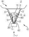
图1图示了处于舒张期的人类心脏的剖视图;Figure 1 illustrates a cross-sectional view of a human heart in diastole;
图2图示了处于收缩期的人类心脏的剖视图;Figure 2 illustrates a cross-sectional view of a human heart in systole;
图3图示了处于舒张期的人类心脏的剖视图,其中显示了腱索将二尖瓣和三尖瓣的小叶附接至心室壁;3 illustrates a cross-sectional view of a human heart in diastole showing the chordae tendineae attaching the leaflets of the mitral and tricuspid valves to the ventricular wall;
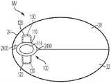
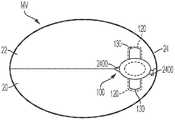
图4图示了从二尖瓣的心房侧观察时小叶闭合的健康二尖瓣;Figure 4 illustrates a healthy mitral valve with closed leaflets when viewed from the atrial side of the mitral valve;
图5图示了从二尖瓣的心房侧观察时在小叶之间具有可见间隙的功能失调的二尖瓣;Figure 5 illustrates a dysfunctional mitral valve with visible gaps between the leaflets when viewed from the atrial side of the mitral valve;
图6图示了在后小叶和前小叶之间具有宽间隙的二尖瓣;Figure 6 illustrates a mitral valve with a wide gap between the posterior and anterior leaflets;
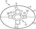
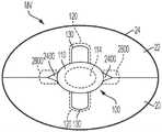
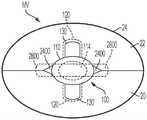
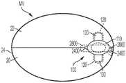
图7图示了从三尖瓣的心房侧观察的三尖瓣;Figure 7 illustrates the tricuspid valve viewed from the atrial side of the tricuspid valve;
图8-图14显示了处于各种部署阶段的可植入假体装置的示例;Figures 8-14 show examples of implantable prosthetic devices at various stages of deployment;
图15-图20显示了图8-图14的可植入假体装置被输送并植入原生瓣膜内;Figures 15-20 show the implantable prosthetic device of Figures 8-14 being delivered and implanted within a native valve;
图21显示了植入原生瓣膜内的图8-图14的可植入假体装置;Figure 21 shows the implantable prosthetic device of Figures 8-14 implanted within a native valve;
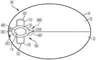
图22显示了植入原生瓣膜内的第一示例位置的可植入假体装置;Figure 22 shows an implantable prosthetic device implanted within a native valve in a first example position;
图23是植入在图22所示的原生瓣膜内的第一位置的可植入假体装置的横截面图,截面沿图22中的线23-23指示的平面截取;Fig. 23 is a cross-sectional view of the implantable prosthetic device implanted in the first position within the native valve shown in Fig. 22, the cross-section being taken along the plane indicated by line 23-23 in Fig. 22;
图24显示了从原生瓣膜的心室侧观察的植入在图22所示的原生瓣膜内的第一位置的可植入假体装置;Figure 24 shows the implantable prosthetic device implanted in the first position within the native valve shown in Figure 22, viewed from the ventricular side of the native valve;
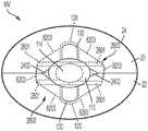
图25显示了从原生瓣膜的心房侧观察的植入在图22所示的原生瓣膜内的第一位置的可植入假体装置;Figure 25 shows the implantable prosthetic device implanted in the first position within the native valve shown in Figure 22, viewed from the atrial side of the native valve;
图26显示了从原生瓣膜的心室侧观察的植入原生瓣膜内的第二示例位置的图22的可植入假体装置;Figure 26 shows the implantable prosthetic device of Figure 22 in a second example position implanted within the native valve, viewed from the ventricular side of the native valve;
图27显示了从原生瓣膜的心房侧观察的植入在图26所示的原生瓣膜内的第二示例位置的图22的可植入假体装置;Figure 27 shows the implantable prosthetic device of Figure 22 implanted in a second example position within the native valve shown in Figure 26, viewed from the atrial side of the native valve;
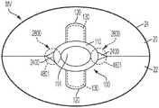
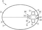
图28显示了植入原生瓣膜内的第一示例位置的可植入假体装置的示例;Figure 28 shows an example of an implantable prosthetic device implanted in a first example location within a native valve;
图29是植入在图28所示的原生瓣膜内的第一位置的可植入假体装置的横截面图,截面沿图28中的线29-29指示的平面截取;Fig. 29 is a cross-sectional view of the implantable prosthetic device implanted in the first position within the native valve shown in Fig. 28, the cross-section being taken along the plane indicated by line 29-29 in Fig. 28;
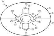
图30显示了当心脏处于舒张期时观察的植入在图28所示的瓣膜内的第一位置的可植入假体装置;Figure 30 shows the implantable prosthetic device implanted in the first position within the valve shown in Figure 28 as viewed when the heart is in diastole;
图31是植入在图30所示的原生瓣膜内的第一位置的可植入假体装置的横截面图,截面沿图30中所示的线31-31指示的平面截取;Figure 31 is a cross-sectional view of the implantable prosthetic device implanted in the first position within the native valve shown in Figure 30, the cross-section taken along the plane indicated by line 31-31 shown in Figure 30;
图32显示了当心脏处于收缩期时观察的植入在图28所示的瓣膜内的第一位置的可植入假体装置;Figure 32 shows the implantable prosthetic device implanted in the first position within the valve shown in Figure 28 when the heart is in systole;
图33是植入在图32所示的原生瓣膜内的第一位置的可植入假体装置的横截面图,截面沿图32所示的线33-33指示的平面截取;Figure 33 is a cross-sectional view of the implantable prosthetic device implanted in the first position within the native valve shown in Figure 32, the cross-section taken along the plane indicated by line 33-33 shown in Figure 32;
图34显示了从原生瓣膜的心室侧观察的植入在图28所示的原生瓣膜内的第一位置的可植入假体装置;Figure 34 shows the implantable prosthetic device implanted in the first position within the native valve shown in Figure 28, viewed from the ventricular side of the native valve;
图35显示了从原生瓣膜的心房侧观察的植入在图28所示的原生瓣膜内的第一位置的可植入假体装置;Figure 35 shows the implantable prosthetic device implanted in the first position within the native valve shown in Figure 28, viewed from the atrial side of the native valve;
图36显示了从原生瓣膜的心室侧观察的植入原生瓣膜内的第二示例位置的图28的可植入假体装置;Figure 36 shows the implantable prosthetic device of Figure 28 in a second example position implanted within the native valve, viewed from the ventricular side of the native valve;
图37显示了从原生瓣膜的心房侧观察的植入在图36所示的原生瓣膜内的第二示例位置的图28的可植入假体装置;Figure 37 shows the implantable prosthetic device of Figure 28 implanted in a second example position within the native valve shown in Figure 36, viewed from the atrial side of the native valve;
图38A显示了植入原生瓣膜内的第一示例位置的可植入假体装置的示例;Figure 38A shows an example of an implantable prosthetic device implanted within a native valve at a first example location;
图38B显示了植入原生瓣膜内的第一示例位置的可植入假体装置的示例;Figure 38B shows an example of an implantable prosthetic device implanted within a native valve at a first example location;
图39A是植入在图38A所示的原生瓣膜内的第一位置的可植入假体装置的横截面图,截面沿图38A中的线39A-39A指示的平面截取;Figure 39A is a cross-sectional view of the implantable prosthetic device implanted in the first position within the native valve shown in Figure 38A, the cross-section taken along the plane indicated by
图39B是植入在图38B所示的原生瓣膜内的第一位置的可植入假体装置的横截面图,截面沿图38B中的线39B-39B指示的平面截取;Figure 39B is a cross-sectional view of the implantable prosthetic device implanted in the first position within the native valve shown in Figure 38B, the cross-section taken along the plane indicated by
图40A显示了当心脏处于舒张期时观察的植入在图38A所示的原生瓣膜内的第一位置的可植入假体装置;Figure 40A shows the implantable prosthetic device implanted in the first position within the native valve shown in Figure 38A as viewed when the heart is in diastole;
图40B显示了当心脏处于舒张期时观察的植入在图38B所示的原生瓣膜内的第一位置的可植入假体装置;Figure 40B shows the implantable prosthetic device implanted in the first position within the native valve shown in Figure 38B as viewed when the heart is in diastole;
图41A是植入在图40A中所示的原生瓣膜内的第一位置的可植入假体装置的横截面图,其中截面沿图40A中所示的线41A-41A指示的平面截取;Figure 41A is a cross-sectional view of the implantable prosthetic device implanted in the first position within the native valve shown in Figure 40A, wherein the cross-section is taken along the plane indicated by
图41B是植入在图40B中所示的原生瓣膜内的第一位置的可植入假体装置的横截面图,其中截面沿图40B中所示的线41B-41B指示的平面截取;Figure 41B is a cross-sectional view of the implantable prosthetic device implanted in the first position within the native valve shown in Figure 40B, wherein the cross-section is taken along the plane indicated by
图42A显示了当心脏处于收缩期时观察的植入在图38A所示的原生瓣膜内的第一位置的可植入假体装置;Figure 42A shows the implantable prosthetic device implanted in the first position within the native valve shown in Figure 38A when the heart is in systole;
图42B显示了当心脏处于收缩期时观察的植入在图38B所示的原生瓣膜内的第一位置的可植入假体装置;Figure 42B shows the implantable prosthetic device implanted in the first position within the native valve shown in Figure 38B as viewed when the heart is in systole;
图43A是植入在图42A所示的原生瓣膜内的第一位置的可植入假体装置的横截面图,其中截面沿图42A所示的线43A-43A指示的平面截取;Figure 43A is a cross-sectional view of the implantable prosthetic device implanted in the first position within the native valve shown in Figure 42A, wherein the cross-section is taken along the plane indicated by
图43B是植入在图42B中所示的原生瓣膜内的第一位置的可植入假体装置的横截面图,其中截面沿图42B中所示的线43B-43B指示的平面截取;Figure 43B is a cross-sectional view of the implantable prosthetic device implanted in the first position within the native valve shown in Figure 42B, wherein the cross-section is taken along the plane indicated by
图44A显示了从原生瓣膜的心室侧观察的植入在图38A所示的原生瓣膜内的第一位置的可植入假体装置;Figure 44A shows the implantable prosthetic device implanted in the first position within the native valve shown in Figure 38A, viewed from the ventricular side of the native valve;
图44B显示了从原生瓣膜的心室侧观察的植入在图38B所示的原生瓣膜内的第一位置的可植入假体装置;Figure 44B shows the implantable prosthetic device implanted in the first position within the native valve shown in Figure 38B, viewed from the ventricular side of the native valve;
图45A显示了从原生瓣膜的心房侧观察的植入在图38A所示的原生瓣膜内的第一位置的可植入假体装置;Figure 45A shows the implantable prosthetic device implanted in the first position within the native valve shown in Figure 38A, viewed from the atrial side of the native valve;
图45B显示了从原生瓣膜的心房侧观察的植入在图38B所示的原生瓣膜内的第一位置的可植入假体装置;Figure 45B shows the implantable prosthetic device implanted in the first position within the native valve shown in Figure 38B, viewed from the atrial side of the native valve;
图46A显示了从原生瓣膜的心室侧观察的植入在原生瓣膜内的第二示例位置的图38A的可植入假体装置;Figure 46A shows the implantable prosthetic device of Figure 38A in a second example position implanted within the native valve as viewed from the ventricular side of the native valve;
图46B显示了从原生瓣膜的心室侧观察的植入在原生瓣膜内的第二示例位置的图38B的可植入假体装置;Figure 46B shows the implantable prosthetic device of Figure 38B implanted in a second example position within the native valve as viewed from the ventricular side of the native valve;
图47A显示了从原生瓣膜的心房侧观察的植入在图46A所示的二尖瓣内的第二示例位置的图38A的可植入假体装置;Figure 47A shows the implantable prosthetic device of Figure 38A implanted in a second example position within the mitral valve shown in Figure 46A, viewed from the atrial side of the native valve;
图47B显示了从原生瓣膜的心房侧观察的植入到图46B所示的二尖瓣内的第二示例位置的图38B的可植入假体装置;Figure 47B shows the implantable prosthetic device of Figure 38B implanted in a second example position within the mitral valve shown in Figure 46B, viewed from the atrial side of the native valve;
图48A显示了植入原生瓣膜内的第一示例位置的可植入假体装置的示例;Figure 48A shows an example of an implantable prosthetic device implanted in a first example location within a native valve;
图48B显示了植入原生瓣膜内的第一示例位置的可植入假体装置的示例;Figure 48B shows an example of an implantable prosthetic device implanted in a first example location within a native valve;
图49A是植入在图48A所示的原生瓣膜内的第一位置的可植入假体装置的横截面图,其中截面沿图48A中的线49A-49A指示的平面截取;Figure 49A is a cross-sectional view of the implantable prosthetic device implanted in the first position within the native valve shown in Figure 48A, wherein the cross-section is taken along the plane indicated by
图49B是植入在图48B所示的原生瓣膜内的第一位置的可植入假体装置的横截面图,其中截面沿图48B中的线49B-49B指示的平面截取;Figure 49B is a cross-sectional view of the implantable prosthetic device implanted in the first position within the native valve shown in Figure 48B, wherein the cross-section is taken along the plane indicated by
图50A显示了当心脏处于舒张期时观察的植入在图48A所示的原生瓣膜内的第一位置的可植入假体装置;Figure 50A shows the implantable prosthetic device implanted in the first position within the native valve shown in Figure 48A as viewed when the heart is in diastole;
图50B显示了当心脏处于舒张期时观察的植入在图48B所示的原生瓣膜内的第一位置的可植入假体装置;Figure 50B shows the implantable prosthetic device implanted in the first position within the native valve shown in Figure 48B as viewed when the heart is in diastole;
图51A是植入在图50A中所示的原生瓣膜内的第一位置的可植入假体装置的横截面图,截面沿图50A中所示的线51A-51A指示的平面截取;Figure 51A is a cross-sectional view of the implantable prosthetic device implanted in the first position within the native valve shown in Figure 50A, the cross-section taken along the plane indicated by
图51B是植入在图50B中所示的原生瓣膜内的第一位置的可植入假体装置的横截面图,截面沿图50B中所示的线51B-51B指示的平面截取;Figure 51B is a cross-sectional view of the implantable prosthetic device implanted in the first position within the native valve shown in Figure 50B, the cross-section taken along the plane indicated by
图52A显示了当心脏处于收缩期时观察的植入在图48A所示的原生瓣膜内的第一位置的可植入假体装置;Figure 52A shows the implantable prosthetic device implanted in the first position within the native valve shown in Figure 48A when the heart is in systole;
图52B显示了当心脏处于收缩期时观察的植入在图48B所示的原生瓣膜内的第一位置的可植入假体装置;Figure 52B shows the implantable prosthetic device implanted in the first position within the native valve shown in Figure 48B as viewed when the heart is in systole;
图53A是植入在图52A所示的原生瓣膜内的第一位置的可植入假体装置的横截面图,截面沿图52A所示的线53A-53A指示的平面截取;Figure 53A is a cross-sectional view of the implantable prosthetic device implanted in the first position within the native valve shown in Figure 52A, the cross-section taken along the plane indicated by
图53B是植入在图52B中所示的原生瓣膜内的第一位置的可植入假体装置的横截面图,截面沿图52B中所示的线53B-53B指示的平面截取;Figure 53B is a cross-sectional view of the implantable prosthetic device implanted in the first position within the native valve shown in Figure 52B, the cross-section taken along the plane indicated by
图54A显示了从原生瓣膜的心室侧观察的植入在图48A所示的原生瓣膜内的第一位置的可植入假体装置;Figure 54A shows the implantable prosthetic device implanted in the first position within the native valve shown in Figure 48A, viewed from the ventricular side of the native valve;
图54B显示了从原生瓣膜的心室侧观察的植入在图48B所示的原生瓣膜内的第一位置的可植入假体装置;Figure 54B shows the implantable prosthetic device implanted in the first position within the native valve shown in Figure 48B, viewed from the ventricular side of the native valve;
图55A显示了从原生瓣膜的心房侧观察的植入在图48A所示的原生瓣膜内的第一位置的可植入假体装置;Figure 55A shows the implantable prosthetic device implanted in the first position within the native valve shown in Figure 48A, viewed from the atrial side of the native valve;
图55B显示了从原生瓣膜的心房侧观察的植入在图48B所示的原生瓣膜内的第一位置的可植入假体装置;Figure 55B shows the implantable prosthetic device implanted in the first position within the native valve shown in Figure 48B, viewed from the atrial side of the native valve;
图56A显示了从原生瓣膜的心室侧观察的植入在原生瓣膜内的第二示例位置的图48A的可植入假体装置;Figure 56A shows the implantable prosthetic device of Figure 48A in a second example position implanted within the native valve as viewed from the ventricular side of the native valve;
图56B显示了从原生瓣膜的心室侧观察的植入在原生瓣膜内的第二示例位置的图48B的可植入假体装置;Figure 56B shows the implantable prosthetic device of Figure 48B implanted in a second example position within the native valve as viewed from the ventricular side of the native valve;
图57A显示了图48A的可植入假体装置,该装置植入在图56A所示的原生瓣膜内的第二示例位置,并且从原生瓣膜的心房侧观察;Figure 57A shows the implantable prosthetic device of Figure 48A implanted in a second example location within the native valve shown in Figure 56A, and viewed from the atrial side of the native valve;
图57B显示了图48B的可植入假体装置,该装置植入图56B所示的原生瓣膜内的第二示例位置,并且从原生瓣膜的心房侧观察;Figure 57B shows the implantable prosthetic device of Figure 48B implanted in a second example location within the native valve shown in Figure 56B and viewed from the atrial side of the native valve;
图58显示了植入原生瓣膜内的第一示例位置的可植入假体装置的示例;Figure 58 shows an example of an implantable prosthetic device implanted in a first example location within a native valve;
图59是植入在图58所示的原生瓣膜内的第一位置的可植入假体装置的横截面图,截面沿图58中的线59-59指示的平面截取;Fig. 59 is a cross-sectional view of the implantable prosthetic device implanted in the first position within the native valve shown in Fig. 58, the cross-section being taken along the plane indicated by line 59-59 in Fig. 58;
图60显示了当心脏处于舒张期时观察的植入在图58所示的原生瓣膜内的第一位置的可植入假体装置;Figure 60 shows the implantable prosthetic device implanted in the first position within the native valve shown in Figure 58 as viewed when the heart is in diastole;
图61是植入在图60中所示的原生瓣膜内的第一位置的可植入假体装置的横截面图,其中截面沿图60中所示的线61-61指示的平面截取;Figure 61 is a cross-sectional view of the implantable prosthetic device implanted in the first position within the native valve shown in Figure 60, wherein the cross-section is taken along the plane indicated by line 61-61 shown in Figure 60;
图62显示了当心脏处于收缩期时观察的植入在图58所示的原生瓣膜内的第一位置的可植入假体装置;Figure 62 shows the implantable prosthetic device implanted in the first position within the native valve shown in Figure 58 as viewed when the heart is in systole;
图63是沿图62所示的线63-63观察的、植入在图62所示的原生瓣膜内的第一位置的可植入假体装置的横截面图;Figure 63 is a cross-sectional view of the implantable prosthetic device implanted in the first position within the native valve shown in Figure 62, viewed along line 63-63 shown in Figure 62;
图64显示了从原生瓣膜的心室侧观察的植入在图58所示的原生瓣膜内的第一位置的可植入假体装置;Figure 64 shows the implantable prosthetic device implanted in the first position within the native valve shown in Figure 58, viewed from the ventricular side of the native valve;
图65显示了从原生瓣膜的心房侧观察的植入在图58所示的原生瓣膜内的第一位置的可植入假体装置;Figure 65 shows the implantable prosthetic device implanted in the first position within the native valve shown in Figure 58, viewed from the atrial side of the native valve;
图66显示了图58的可植入假体装置,该装置植入到原生瓣膜内的第二示例位置,并且从原生瓣膜的心室侧观察;Figure 66 shows the implantable prosthetic device of Figure 58 implanted in a second example position within the native valve and viewed from the ventricular side of the native valve;
图67显示了图58的可植入假体装置,该装置植入在图66所示的原生瓣膜内的第二示例位置,并且从原生瓣膜的心房侧观察;Figure 67 shows the implantable prosthetic device of Figure 58 implanted in a second example location within the native valve shown in Figure 66, and viewed from the atrial side of the native valve;
图68显示了植入原生瓣膜内的第一示例位置的可植入假体装置的示例;Figure 68 shows an example of an implantable prosthetic device implanted in a first example location within a native valve;
图69是植入在图68中所示的原生瓣膜内的第一位置的可植入假体装置的横截面图,截面沿图68中的线69-69指示的平面截取;Fig. 69 is a cross-sectional view of the implantable prosthetic device implanted in the first position within the native valve shown in Fig. 68, the cross-section being taken along the plane indicated by line 69-69 in Fig. 68;
图70显示了当心脏处于舒张期时观察的植入在图68所示瓣膜内的第一位置的可植入假体装置;Figure 70 shows the implantable prosthetic device implanted in the first position within the valve shown in Figure 68 as viewed when the heart is in diastole;
图71是植入在图70所示的原生瓣膜内的第一位置的可植入假体装置的横截面图,截面沿图70所示的线71-71指示的平面截取;Fig. 71 is a cross-sectional view of the implantable prosthetic device implanted in the first position within the native valve shown in Fig. 70, the cross-section being taken along the plane indicated by line 71-71 shown in Fig. 70;
图72显示了当心脏处于收缩期时观察的植入在图68所示瓣膜内的第一位置的可植入假体装置;Figure 72 shows the implantable prosthetic device implanted in the first position within the valve shown in Figure 68 when the heart is in systole;
图73是植入在图72所示的原生瓣膜内的第一位置的可植入假体装置的横截面图,截面沿图72所示的线73-73指示的平面截取;Figure 73 is a cross-sectional view of the implantable prosthetic device implanted in the first position within the native valve shown in Figure 72, the cross-section taken along the plane indicated by line 73-73 shown in Figure 72;
图74显示了从原生瓣膜的心室侧观察的植入在图68所示的原生瓣膜内的第一位置的可植入假体装置;Figure 74 shows the implantable prosthetic device implanted in the first position within the native valve shown in Figure 68, viewed from the ventricular side of the native valve;
图75显示了从原生瓣膜的心房侧观察的植入在图68所示的原生瓣膜内的第一位置的可植入假体装置;Figure 75 shows the implantable prosthetic device implanted in the first position within the native valve shown in Figure 68, viewed from the atrial side of the native valve;
图76显示了图68的可植入假体装置,该装置植入在原生瓣膜内的第二示例位置,并且从原生瓣膜的心室侧观察;Figure 76 shows the implantable prosthetic device of Figure 68 implanted in a second example location within the native valve and viewed from the ventricular side of the native valve;
图77显示了图68的可植入假体装置,该装置植入在图76所示的原生瓣膜内的第二示例位置,并且从原生瓣膜的心房侧观察;Figure 77 shows the implantable prosthetic device of Figure 68 implanted in a second example location within the native valve shown in Figure 76, and viewed from the atrial side of the native valve;
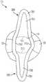
图78是图38A-图47A中所示的可植入假体装置的更具体示例的仰视图;Figure 78 is a bottom view of a more specific example of the implantable prosthetic device shown in Figures 38A-47A;
图79是图38A-图47A中所示的可植入假体装置的更具体示例的仰视图;Figure 79 is a bottom view of a more specific example of the implantable prosthetic device shown in Figures 38A-47A;
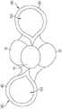
图80是图48A-图57A中所示的可植入假体装置的更具体示例的前视图;Figure 80 is a front view of a more specific example of the implantable prosthetic device shown in Figures 48A-57A;
图81是图80所示的可植入假体装置的仰视图;Figure 81 is a bottom view of the implantable prosthetic device shown in Figure 80;
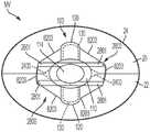
图82显示了植入原生瓣膜内的第一示例位置的可植入假体装置的示例;Figure 82 shows an example of an implantable prosthetic device implanted within a native valve at a first example location;
图83是植入在图82所示的原生瓣膜内的第一位置的可植入假体装置的横截面图,截面沿图82中的线83-83指示的平面截取;Figure 83 is a cross-sectional view of the implantable prosthetic device implanted in the first position within the native valve shown in Figure 82, the cross-section being taken along the plane indicated by line 83-83 in Figure 82;
图84显示了当心脏处于舒张期时观察的植入在图82所示的原生瓣膜内的第一位置的可植入假体装置;Figure 84 shows the implantable prosthetic device implanted in the first position within the native valve shown in Figure 82 as viewed when the heart is in diastole;
图85是植入在图84所示的原生瓣膜内的第一位置的可植入假体装置的横截面图,截面沿图84所示的线85-85指示的平面截取;Fig. 85 is a cross-sectional view of the implantable prosthetic device implanted in the first position within the native valve shown in Fig. 84, the cross-section being taken along the plane indicated by line 85-85 shown in Fig. 84;
图86显示了当心脏处于收缩期时观察的植入在图82所示的原生瓣膜内的第一位置的可植入假体装置;Figure 86 shows the implantable prosthetic device implanted in the first position within the native valve shown in Figure 82 when the heart is in systole;
图87是沿图86所示的线87-87观察的、植入在图86所示的原生瓣膜内的第一位置的可植入假体装置的横截面图;Figure 87 is a cross-sectional view of the implantable prosthetic device implanted in the first position within the native valve shown in Figure 86, taken along line 87-87 shown in Figure 86;
图88显示了从原生瓣膜的心室侧观察的植入在图82所示的原生瓣膜内的第一位置的可植入假体装置;Figure 88 shows the implantable prosthetic device implanted in the first position within the native valve shown in Figure 82, viewed from the ventricular side of the native valve;
图89显示了从原生瓣膜的心房侧观察的植入在图82所示的原生瓣膜内的第一位置的可植入假体装置;Figure 89 shows the implantable prosthetic device implanted in the first position within the native valve shown in Figure 82, viewed from the atrial side of the native valve;
图90显示了图82的可植入假体装置,该装置植入在原生瓣膜内的第二示例位置,并且从原生瓣膜的心室侧观察;和Fig. 90 shows the implantable prosthetic device of Fig. 82 implanted in a second example position within the native valve and viewed from the ventricular side of the native valve; and
图91显示了图82的可植入假体装置,该装置植入在图90所示的原生瓣膜内的第二示例位置,并且从原生瓣膜的心房侧观察。91 shows the implantable prosthetic device of FIG. 82 implanted in a second example location within the native valve shown in FIG. 90 and viewed from the atrial side of the native valve.
具体实施方式Detailed ways
以下描述参考了附图,这些附图说明了本公开的具体实施例。具有不同结构和操作的其他实施例不脱离本公开的范围。The following description refers to the accompanying drawings, which illustrate specific embodiments of the present disclosure. Other embodiments with different structures and operations do not depart from the scope of this disclosure.
本公开的示例实施方式涉及用于修复有缺陷的心脏瓣膜的系统、装置、方法等。应当注意,本文公开了原生瓣膜修复装置、用于输送原生瓣膜修复装置的系统和用于移除植入的原生瓣膜修复装置的系统的各种实施例,并且可以进行这些选项的任何组合,除非特别排除。换言之,所公开的装置和系统的各个部件可以组合,除非相互排斥或以其他方式物理上不可能。此外,这些技术和方法可以在活体动物或模拟物上执行,例如在尸体、尸体心脏、模拟器(例如,模拟身体部位、心脏、组织等)等上。Example embodiments of the present disclosure relate to systems, devices, methods, etc. for repairing defective heart valves. It should be noted that various embodiments of native valve repair devices, systems for delivering native valve repair devices, and systems for removing implanted native valve repair devices are disclosed herein, and any combination of these options may be performed unless Special exclusion. In other words, the various components of the disclosed apparatus and systems can be combined unless mutually exclusive or otherwise physically impossible. Furthermore, these techniques and methods may be performed on live animals or simulants, such as cadavers, cadaveric hearts, simulators (eg, simulating body parts, hearts, tissues, etc.), and the like.
如本文所述,当一个或多个部件被描述为连接、连结、附连、耦合、附接或以其他方式互连时,这种互连可以是在部件之间直接的,或者可以是间接的,例如通过使用一个或多个中间部件。此外,如本文所述,对“构件”、“部件”或“部分”的引用不应限于单个结构构件、部件或元件,而是可以包括部件、构件或元件的组件。此外,如本文所述,术语“基本上”和“大约”被定义为至少接近(并包括)给定值或状态(优选在10%以内,更优选在1%以内,最优选在0.1%以内)。As described herein, when one or more components are described as being connected, joined, attached, coupled, attached or otherwise interconnected, such interconnection can be direct between the components, or such interconnection can be indirect , for example by using one or more intermediate components. Furthermore, as described herein, references to "members," "parts," or "portions" should not be limited to a single structural member, part, or element, but may include assemblies of parts, members, or elements. Also, as used herein, the terms "substantially" and "about" are defined as at least close to (and including) a given value or state (preferably within 10%, more preferably within 1%, and most preferably within 0.1% ).
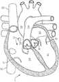
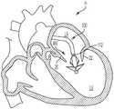
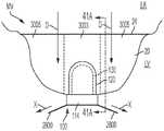
图1和图2分别是人类心脏H在舒张期和收缩期的剖视图。右心室RV和左心室LV分别通过三尖瓣TV和二尖瓣MV与右心房RA和左心房LA分开;即房室瓣。此外,主动脉瓣AV将左心室LV与升主动脉AA分开,并且肺动脉瓣PV将右心室与肺动脉PA分开。这些瓣膜中的每一个具有柔性小叶(例如,图4和图5中所示的小叶20、22),柔性小叶向内延伸穿过相应的孔口,这些孔口在流体流中汇合到一起或“接合(coapt)”以形成单向的流体阻塞表面。本申请的原生瓣膜修复系统主要针对二尖瓣MV进行描述。因此,将更详细地解释左心房LA和左心室LV的解剖结构。然而,本文所述的装置也可用于修复其他原生瓣膜,例如,该装置可用于修复三尖瓣TV、主动脉瓣AV和肺动脉瓣PV。1 and 2 are cross-sectional views of a human heart H in diastole and systole, respectively. The right ventricle RV and left ventricle LV are separated from the right atrium RA and left atrium LA by the tricuspid valve TV and mitral valve MV, respectively; the atrioventricular valve. Furthermore, the aortic valve AV separates the left ventricle LV from the ascending aorta AA, and the pulmonary valve PV separates the right ventricle from the pulmonary artery PA. Each of these valves has flexible leaflets (eg,
左心房LA接收来自肺的含氧血液。在舒张期或舒张时,如图1所示,先前在左心房LA(收缩期)收集的血液通过左心室LV的扩张移动通过二尖瓣MV并进入左心室LV。在收缩期或收缩时,如图2所示,左心室LV收缩以迫使血液通过主动脉瓣AV和升主动脉AA进入体内。在收缩时,二尖瓣MV的小叶闭合以防止血液从左心室LV反流并回到左心房LA,并且血液从肺静脉收集到左心房中。在一个示例实施方式中,本申请所描述的装置用于修复有缺陷的二尖瓣MV的功能。也就是说,这些装置被配置为帮助闭合二尖瓣的小叶以防止血液从左心室LV反流并回到左心房LA。The left atrium LA receives oxygenated blood from the lungs. During diastole or diastole, as shown in Figure 1, blood previously collected in the left atrium LA (systole) moves through the mitral valve MV and into the left ventricle LV by dilation of the left ventricle LV. During systole or contraction, as shown in Figure 2, the left ventricle LV contracts to force blood into the body through the aortic valve AV and the ascending aorta AA. During systole, the leaflets of the mitral valve MV close to prevent blood from refluxing from the left ventricle LV and back into the left atrium LA, and blood collects from the pulmonary veins into the left atrium. In one example embodiment, the devices described herein are used to restore the function of a defective mitral valve MV. That is, these devices are configured to help close the leaflets of the mitral valve to prevent backflow of blood from the left ventricle LV and back into the left atrium LA.
现在参考图1-图7,二尖瓣MV包括两个小叶,前小叶20和后小叶22。二尖瓣MV还包括瓣环24,其是环绕小叶20、22的密度可变的组织纤维环。参考图3,二尖瓣MV通过腱索10锚定在左心室LV的壁上。腱索10是将乳头肌12(即位于腱索的基部和左心室壁内的肌肉)连接到二尖瓣MV的小叶20、22的索状肌腱。乳头肌12用于限制二尖瓣MV的移动并防止二尖瓣恢复。二尖瓣MV响应于左心房LA和左心室LV中的压力变化而打开和闭合。乳头肌不打开或闭合二尖瓣MV。相反,乳头肌支撑二尖瓣MV,抵抗血液在全身循环所需的高压。乳头肌和腱索一起被称为瓣膜下设备,其作用是在二尖瓣闭合时防止二尖瓣MV脱垂到左心房LA。Referring now to FIGS. 1-7 , the mitral valve MV includes two leaflets, an
各种疾病过程可以损害心脏H的一个或多个原生瓣膜的正常功能。这些疾病过程包括退行性过程(例如,巴洛氏病、纤维弹性缺乏)、炎症过程(例如,风湿性心脏病)和感染过程(例如,心内膜炎)。此外,既往心脏病发作(即继发于冠状动脉疾病的心肌梗塞)或其他心脏病(例如心肌病)对左心室LV或右心室RV的损害可能会扭曲原生瓣膜的几何形状,从而导致原生瓣膜功能失调。然而,绝大多数接受瓣膜手术例如二尖瓣MV手术的患者均患有导致原生瓣膜(例如,二尖瓣MV)的小叶(例如,小叶20、22)功能障碍的退行性疾病,这会导致脱垂和反流。Various disease processes can impair the normal function of one or more native valves of the heart H. These disease processes include degenerative processes (eg, Barlow's disease, lack of fibroelasticity), inflammatory processes (eg, rheumatic heart disease), and infectious processes (eg, endocarditis). In addition, damage to the LV or RV of the right ventricle from a previous heart attack (ie, myocardial infarction secondary to coronary artery disease) or other heart disease (eg, cardiomyopathy) may distort the geometry of the native valve, causing the native valve Dysfunctional. However, the vast majority of patients undergoing valve surgery, such as mitral valve MV surgery, have degenerative diseases that lead to dysfunction of the leaflets (eg,
通常,原生瓣膜可能以两种不同的方式发生功能障碍:(1)瓣膜狭窄;以及(2)瓣膜反流。当原生瓣膜未完全打开并因此导致血流阻塞时,就会发生瓣膜狭窄。通常,瓣膜狭窄是由瓣膜小叶上的钙化物质积聚引起的,这会导致小叶变厚并损害瓣膜完全打开以允许血液向前流动的能力。In general, native valves can malfunction in two distinct ways: (1) valve stenosis; and (2) valve regurgitation. Valve stenosis occurs when the native valve does not open fully and therefore blocks blood flow. Typically, valve stenosis is caused by the buildup of calcified material on the valve leaflets, which causes the leaflets to thicken and impair the valve's ability to open fully to allow blood to flow forward.
第二种类型的瓣膜功能障碍,瓣膜反流,发生在瓣膜的小叶没有完全闭合从而导致血液泄漏回先前的腔室(例如,导致血液从左心室泄漏到左心房)时。有三种机制导致原生瓣膜反流或功能不全—包括Carpentier的I型、II型和III型功能故障。Carpentier I型故障涉及瓣环扩张,使得正常功能的小叶彼此分离,并且无法形成紧密的密封(即小叶没有正确接合)。I型机制故障包括小叶穿孔,如心内膜炎中存在的那样。Carpentier II型功能障碍涉及原生瓣膜的一个或多个小叶在对合平面上方脱垂。Carpentier的III型功能故障涉及限制原生瓣膜的一个或多个小叶的运动,使得小叶异常受限于瓣环平面下方。风湿病(Ma)或心室扩张(IIIb)可能导致小叶限制。The second type of valve dysfunction, valve regurgitation, occurs when the leaflets of the valve do not close completely, causing blood to leak back into the previous chamber (eg, causing blood to leak from the left ventricle to the left atrium). There are three mechanisms that lead to native valve regurgitation or insufficiency—including Carpentier's Type I, Type II, and Type III malfunctions. Carpentier Type I failure involves annulus expansion such that normally functioning leaflets separate from each other and fail to form a tight seal (ie, the leaflets do not coaptate properly). Type I mechanistic failure includes lobular perforation, as present in endocarditis. Carpentier type II dysfunction involves prolapse of one or more leaflets of the native valve above the plane of coaptation. Carpentier's Type III malfunction involves restricting the movement of one or more leaflets of the native valve such that the leaflet abnormalities are confined below the plane of the annulus. Rheumatism (Ma) or ventricular dilatation (IIIb) may cause lobular restriction.
参考图4,当健康二尖瓣MV处于闭合位置时,前小叶20和后小叶22接合,这防止血液从左心室LV泄漏到左心房LA。参考图5,当二尖瓣MV的前小叶20和/或后小叶22在收缩时移位到左心房LA时,就会发生反流。这种未能接合导致前小叶20和后小叶22之间的间隙26,这允许血液在收缩时从左心室LV流回左心房LA。如上所述,小叶(例如二尖瓣MV的小叶20、22)可能有几种不同的方式发生功能故障,从而可以导致反流。Referring to Figure 4, when the healthy mitral valve MV is in the closed position, the
参照图6,在某些情况下,当二尖瓣处于闭合位置时(即,在收缩期),患者的二尖瓣MV在前小叶20和后小叶22之间可以具有宽间隙26。例如,间隙26可以具有在约2.5mm和约17.5mm之间(例如在约5mm和约15mm之间,例如在约7.5mm和约12.5mm之间,例如约10mm)的宽度W。在一些情况下,间隙26可以具有大于15mm的宽度W。在任何上述情况下,希望瓣膜修复装置能够接合前小叶20和后小叶22以闭合间隙26并防止血液通过二尖瓣MV反流。Referring to FIG. 6 , under certain circumstances, the patient's mitral valve MV may have a
尽管狭窄或反流可影响任何瓣膜,但发现狭窄主要影响主动脉瓣AV或肺动脉瓣PV,并且发现反流主要影响二尖瓣MV或三尖瓣TV。瓣膜狭窄和瓣膜反流都会增加心脏H的工作量,并且如果不进行治疗可能会导致非常严重的情况;例如心内膜炎、充血性心力衰竭、永久性心脏损伤、心脏骤停以及最终死亡。因为心脏的左侧(即左心房LA、左心室LV、二尖瓣MV和主动脉瓣AV)主要负责使血液在全身循环,所以二尖瓣MV或主动脉瓣AV的功能故障尤其成问题并且经常危及生命。因此,由于心脏左侧的压力明显较高,二尖瓣MV或主动脉瓣AV的功能失调更加成问题。Although stenosis or regurgitation can affect any valve, stenosis was found to primarily affect the aortic valve AV or pulmonic valve PV, and regurgitation was found to primarily affect the mitral valve MV or tricuspid valve TV. Both valve stenosis and valve regurgitation increase the workload of the heart and can lead to very serious conditions if left untreated; such as endocarditis, congestive heart failure, permanent heart damage, cardiac arrest, and ultimately death. Because the left side of the heart (ie, left atrium LA, left ventricle LV, mitral valve MV, and aortic valve AV) is primarily responsible for circulating blood throughout the body, malfunction of the mitral valve MV or aortic valve AV is particularly problematic and Often life-threatening. Therefore, dysfunction of the mitral valve MV or aortic valve AV is more problematic due to the significantly higher pressure on the left side of the heart.
可以修复或更换发生故障的原生心脏瓣膜。修复通常涉及患者原生瓣膜的保留和矫正。替换通常涉及用生物或机械替代物更换患者的原生瓣膜。通常,主动脉瓣AV和肺动脉瓣PV更容易发生狭窄。由于小叶造成的狭窄损伤是不可逆的,因此狭窄的主动脉瓣或狭窄的肺动脉瓣最常规的治疗方法是用手术植入的心脏瓣膜去除和替换瓣膜,或用经导管心脏瓣膜置换瓣膜。二尖瓣MV和三尖瓣TV更容易发生小叶变形,如上所述,这会阻止二尖瓣或三尖瓣正常闭合,并允许血液从心室反流或流回到心房(例如,变形的二尖瓣MV可能允许从左心室LV反流或流回到左心房LA)。血液从心室反流或流回到心房会导致瓣膜功能不全。二尖瓣MV或三尖瓣TV的结构或形状的变形是可以修复的。此外,由于腱索10变得功能失调(例如,腱索可能伸展或破裂),可发生反流,这允许前小叶20和后小叶22恢复,使得血液反流到左心房LA。由功能失调的腱索引起的问题可以通过修复腱索或二尖瓣的结构来修复(例如,通过将小叶20、22固定在二尖瓣的受影响部分)。A failed native heart valve can be repaired or replaced. Repair usually involves preservation and correction of the patient's native valve. Replacement typically involves replacing the patient's native valve with a biological or mechanical replacement. In general, aortic valve AV and pulmonary valve PV are more prone to stenosis. Because stenotic damage to the leaflets is irreversible, the most conventional treatment for a stenotic aortic valve or a stenotic pulmonic valve is to remove and replace the valve with a surgically implanted heart valve, or to replace the valve with a transcatheter heart valve. The mitral valve MV and tricuspid valve TV are more prone to leaflet deformation, which, as described above, prevents the mitral or tricuspid valve from closing properly and allows blood to flow back from the ventricle or back into the atrium (eg, deformed mitral valve The cusp MV may allow regurgitation from the left ventricle LV or back into the left atrium LA). Regurgitation of blood from the ventricle or back into the atrium can lead to valve insufficiency. Deformations in the structure or shape of the mitral valve MV or tricuspid valve TV can be repaired. Furthermore, as the chordae tendineae 10 become dysfunctional (eg, the chordae tendineae may stretch or rupture), reflux can occur, which allows the
本文公开的装置和程序涉及修复二尖瓣结构或从二尖瓣移除植入的修复装置。然而,应当理解,本文提供的装置和概念可用于修复任何原生瓣膜或原生瓣膜的任何部件。现在参考图7,本文提供的任何装置和概念可用于修复三尖瓣TV。例如,本文提供的装置和概念可用于前小叶30、间隔小叶32和后小叶34中的任意两个之间,以防止血液从右心室反流到右心房。此外,本文提供的任何装置和概念可以一起用于所有三个小叶30、32、34,以防止血液从右心室反流到右心房。也就是说,本文提供的瓣膜修复装置可以位于三个小叶30、32、34之间的中心。The devices and procedures disclosed herein relate to repairing mitral valve structures or removing implanted repair devices from the mitral valve. It should be understood, however, that the devices and concepts provided herein can be used to repair any native valve or any component of a native valve. Referring now to FIG. 7, any of the devices and concepts provided herein can be used to repair a tricuspid TV. For example, the devices and concepts provided herein may be used between any two of the
本专利申请中公开的概念可以应用于多种不同的瓣膜修复装置。在2018年10月10日提交的美国临时专利申请序列号No.62/744,031、2019年1月8日提交的专利合作条约申请号PCT/US2019/012707以及专利合作条约申请号PCT/US2018/028189中公开了可以应用本文公开的概念的瓣膜修复装置的一些示例,以上申请通过引用将其全部内容并入本文。The concepts disclosed in this patent application can be applied to a variety of different valve repair devices. US Provisional Patent Application Serial No. 62/744,031, filed October 10, 2018, Patent Cooperation Treaty Application No. PCT/US2019/012707, filed January 8, 2019, and Patent Cooperation Treaty Application No. PCT/US2018/028189 Some examples of valve repair devices to which the concepts disclosed herein may be applied are disclosed in , the entire contents of which are incorporated herein by reference.
图8-图14图示了瓣膜修复装置的示例。示例性可植入假体装置可以具有对合或接合元件(例如,间隔物等)和至少一个锚。接合元件配置成定位在原生心脏瓣膜孔口内以帮助填充空间并形成更有效的密封,从而减少或防止上述反流。接合元件可具有不透血的结构,并且该结构允许原生小叶在心室收缩期间围绕接合元件闭合以阻止血液分别从左心室或右心室流回左心房或右心房。假体装置可配置为密封两个或三个原生瓣膜小叶;也就是说,该装置可用于原生二尖瓣(二尖瓣)和三尖瓣。接合元件在本文中有时被称为间隔物,因为接合元件可以填充未完全闭合的功能不正常的原生二尖瓣或三尖瓣小叶之间的空间。8-14 illustrate examples of valve repair devices. Exemplary implantable prosthetic devices may have coaptation or engagement elements (eg, spacers, etc.) and at least one anchor. The engagement element is configured to be positioned within the native heart valve orifice to help fill the space and form a more effective seal, thereby reducing or preventing the aforementioned regurgitation. The engagement element may have a blood-impermeable structure that allows the native leaflet to close around the engagement element during ventricular systole to prevent blood flow from the left or right ventricle back to the left or right atrium, respectively. The prosthetic device can be configured to seal two or three native valve leaflets; that is, the device can be used with both native mitral (mitral) and tricuspid valves. Coating elements are sometimes referred to herein as spacers because they can fill the spaces between the leaflets of a dysfunctional native mitral or tricuspid valve that are not fully closed.
接合元件(例如,间隔物等)可以具有各种形状。在一些实施例中,接合元件可以具有细长的圆柱形状,其具有圆形横截面形状。在一些实施例中,接合元件可具有椭圆形横截面形状、新月形横截面形状或各种其他非圆柱形形状。接合元件可具有位于左心房中或附近的心房部分、位于左心室中或附近的心室或下部,以及在原生二尖瓣小叶之间延伸的侧表面。在配置用于三尖瓣的实施例中,心房或上部定位在右心房内或附近,并且心室或下部定位在右心室内或附近,以及在原生三尖瓣小叶之间延伸的侧表面。Engagement elements (eg, spacers, etc.) can have various shapes. In some embodiments, the engagement element may have an elongated cylindrical shape with a circular cross-sectional shape. In some embodiments, the engagement element may have an oval cross-sectional shape, a crescent cross-sectional shape, or various other non-cylindrical shapes. The engagement element may have an atrial portion located in or near the left atrium, a ventricle or lower portion located in or near the left ventricle, and a lateral surface extending between the native mitral valve leaflets. In embodiments configured for use with a tricuspid valve, the atrium or superior portion is positioned in or near the right atrium, and the ventricle or inferior portion is positioned in or near the right ventricle, and the lateral surfaces extending between the native tricuspid valve leaflets.
锚可以被配置为将装置固定到一个或两个原生二尖瓣小叶,使得接合元件定位在两个原生小叶之间。在配置用于三尖瓣的实施例中,锚配置成将装置固定到一个、两个或三个三尖瓣小叶,使得接合元件定位在三个原生小叶之间。在一些实施例中,锚可以在与接合元件的心室部分相邻的位置处附接到接合元件。在一些实施例中,锚可以附接至接合元件同样附接到的轴或致动丝或其他致动元件。在一些实施例中,锚和接合元件可以独立定位。在一些实施例中,锚和接合元件可以同时定位。锚可以配置为抓握小叶。Anchors can be configured to secure the device to one or both native mitral valve leaflets such that the coaptation element is positioned between the two native leaflets. In embodiments configured for use with a tricuspid valve, the anchors are configured to secure the device to one, two or three tricuspid valve leaflets such that the engagement element is positioned between the three native leaflets. In some embodiments, the anchor may be attached to the engagement element at a location adjacent to the ventricular portion of the engagement element. In some embodiments, the anchor may be attached to a shaft or actuation wire or other actuation element to which the engagement element is also attached. In some embodiments, the anchors and engagement elements may be positioned independently. In some embodiments, the anchor and engagement element may be positioned simultaneously. The anchor can be configured to grasp the leaflet.
假体装置可以被配置为通过输送护套植入。有关输送方法示例的附加信息可在美国专利申请号8,449,599以及美国专利申请公开号2014/0222136、2014/0067052和2016/0331523中找到,以上申请均通过引用整体并入本文。此外,这些方法可以在活体动物或模拟物上执行,例如在尸体、尸体心脏、模拟器(例如,模拟身体部位、心脏、组织等)等上进行必要的必要修改。The prosthetic device can be configured to be implanted through a delivery sheath. Additional information regarding examples of delivery methods can be found in US Patent Application No. 8,449,599 and US Patent Application Publication Nos. 2014/0222136, 2014/0067052 and 2016/0331523, all of which are incorporated herein by reference in their entirety. Furthermore, these methods can be performed on live animals or simulants, such as cadavers, cadaver hearts, simulators (eg, simulating body parts, hearts, tissues, etc.) with necessary modifications as necessary.
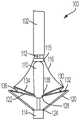
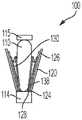
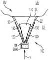
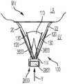
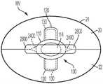
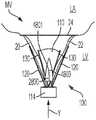
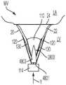
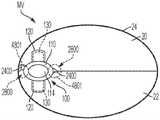
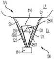
现在参考图8-图14,示意性地示出的可植入假体装置100的示例显示在部署的各个阶段。然而,可植入假体装置可以采用如上所述的多种不同形式。例如,本申请的特征可以包括在美国临时专利申请序列号62/744,031、专利合作条约申请号PCT/US2019/012707和/或专利合作条约申请号PCT/US2018/028189中公开的任何可植入假体装置中。装置100可以包括本申请中讨论的可植入假体装置的任何其他特征,并且装置100可以定位成接合瓣膜组织(例如,小叶20、22)作为任何合适的瓣膜修复系统(例如,本申请中公开的任何瓣膜修复系统)的一部分。Referring now to FIGS. 8-14 , examples of the implantable
装置100可以从输送护套102中部署并且可以包括接合部分104和/或锚定部分106。装置100的接合部分104包括适于植入在原生瓣膜(例如,原生二尖瓣、原生三尖瓣等)的小叶之间的接合元件或间隔物110并且可滑动地附接到致动构件或致动元件112(例如,导线、轴、杆、线、缝合线、系绳等)。锚定部分106可在打开状态和闭合状态之间致动并且可以采用多种形式,例如桨叶、闩锁、卡扣、紧固件、抓握元件等。致动元件112的致动(例如致动丝的致动等)打开和闭合装置100的锚定部分106以在植入期间抓住二尖瓣小叶。致动元件112可以采用多种不同的形式。例如,致动元件可以是螺纹的,使得致动元件的旋转使锚定部分106相对于接合部分104移动。或者,致动元件可以是无螺纹的,使得推动或拉动致动元件112将锚定部分106相对于接合部分104移动。
在一些实施方式中,装置100的锚定部分106包括通过部分124、126、128连接在帽114和接合元件110之间的外桨叶120和内桨叶122。部分124、126、128可以连结、铰接和/或柔性地在下面描述的所有位置之间移动。外桨叶120、内桨叶122、接合元件110和帽114通过部分124、126和128的互连可以将装置限制在本文所示的位置和移动。在一些实施方式中,该装置仅包括一个外桨叶120和一个内桨叶122,并且这些可以以不同的方式配置。In some embodiments, the anchoring
致动构件或致动元件112在锚定部分106的远侧连接处通过输送护套和/或推管/杆和/或接合元件或间隔物110延伸到帽114。伸出和缩回致动元件112分别增加和减小接合元件110和帽114之间的间距。可选的附接工具或套环(未示出)将接合元件110可移除地附接到推管或杆和/或输送护套102,使得致动元件112在致动期间沿着致动元件112滑动以打开和闭合锚定部分106的桨叶120、122。在装置100连接到瓣膜组织之后,如果需要从瓣膜组织中移除装置100,可以使用取回装置连接到套环115,使得致动元件可以延伸穿过套环115和接合元件110,以接合锚定部分106,从而打开桨叶120、122并将装置100从瓣膜组织移除。可以使用的取回装置的示例在2019年11月20日提交的PCT申请号PCT/US2019/062391中示出,该申请通过引用整体并入本文。The actuation member or
现在参考图11,锚定部分106包括附接部分或抓握构件。所示的抓握构件显示为倒钩扣130,其包括基部或固定臂132、可移动臂134、倒钩136和挠性、铰链或接头部分138。但是其他摩擦增强元件可以代替倒钩。固定臂132附接至内桨叶122,其中挠性、铰链或接头部分138设置在接合元件110附近。倒钩扣具有平坦表面并且不装配在桨叶的凹部中。相反,倒钩扣130的平坦部分抵靠内桨叶122的表面设置。挠性、铰链或接头部分138在倒钩扣130的固定臂132和可移动臂134之间提供弹簧力。接头部分138可以是任何合适的柔性部分、铰链或接头,例如柔性接头或铰链、弹簧接头或铰链、枢轴接头或铰链等。在一些实施例中,挠性、铰链或接头部分138是与固定臂132和可移动臂134一体形成的柔性材料片。固定臂132附接到内桨叶122,并且在可移动臂134打开以打开倒钩扣130并暴露倒钩136时相对于内桨叶122保持静止。倒钩扣130通过向附接到可移动臂134的致动线116施加张力而打开,从而使可移动臂134在挠性、铰链或接头部分138上移动、弯曲和/或枢转。Referring now to FIG. 11, the anchoring
在植入期间,桨叶120、122打开和闭合以在桨叶120、122和接合元件110之间捕获或抓住原生二尖瓣小叶。倒钩扣130通过将小叶与倒钩136接合并将小叶夹在可移动臂134和固定臂132之间来进一步固定原生小叶。倒钩扣130的倒钩136增加与小叶的摩擦力或可以部分或完全刺破小叶。致动线116可以被独立地或单独地致动,使得每个倒钩扣130可以被独立地或单独地打开和闭合。单独/独立操作允许一次抓住一个小叶,或者用于将卡扣130重新定位在未被充分抓取的小叶上,而不会改变对另一小叶的成功抓取。倒钩扣130不仅彼此独立地打开和闭合,而且可以独立于内桨叶122的位置而被完全打开和闭合,从而允许根据具体情况需要在各种位置捕获小叶。During implantation, the
可以通过拉动附接致动线116(或其他致动工具)独立地或单独地打开倒钩扣130,该致动线116延伸穿过输送护套102到倒钩扣130。致动线116可以采用多种形式,例如线、缝合线、导线、杆、导管等。倒钩扣130可以是弹簧加载的或以其他方式偏置的,从而在闭合位置,倒钩扣130继续在被捕获或抓取的原生小叶上提供挤压力。无论内桨叶122的位置如何,该挤压力都可以保持恒定或正值。倒钩扣130的倒钩136可以刺穿原生小叶以进一步固定原生小叶。The
现在参考图8,装置100显示为处于伸长或完全打开状态以从输送护套102部署。装置100在完全打开位置加载在输送护套102中,因为完全打开位置占据最小空间并允许使用最小的导管(或对于给定的导管尺寸使用最大的可植入装置100)。在伸长状态下,帽114与接合元件110间隔开,使得锚定部分106的桨叶120、122完全打开或完全延伸。在一些实施例中,在外桨叶120和内桨叶122的内部之间形成的角度约为180度。倒钩扣130在通过输送护套102部署期间保持在闭合状态,使得倒钩136(图11)不会卡住或损坏患者心脏中的护套或组织。Referring now to FIG. 8 ,
现在参考图9,装置100显示为处于伸长解缠结状态,类似于图8,但倒钩扣130处于完全打开位置,范围从大约140度到大约200度,大约170度到大约190度,或者在倒钩扣130的固定部分和可移动部分之间的大约180度。已发现完全打开桨叶120、122和卡扣130可改善在植入装置100期间从患者的解剖结构中解开缠结的容易程度。Referring now to FIG. 9, the
现在参考图10,装置100显示为处于缩短或完全闭合的状态。装置100在缩短状态下的紧凑尺寸允许更容易操纵和放置在心脏内。为了将装置100从伸长状态移动到缩短状态,致动元件112缩回以将帽114拉向接合元件110。外桨叶120和内桨叶122之间的接头、铰链或柔性连接126是运动受到限制或约束的,使得从帽114作用在外桨叶120上的压缩力朝向接合元件110缩回导致桨叶120、122或抓握元件径向向外移动。在从打开位置移动到闭合位置的过程中,外桨叶120与致动元件112保持锐角。外桨叶120可以可选地朝向闭合位置偏置。内桨叶122在相同运动期间移动通过相当大的角度,因为它们在打开状态下远离接合元件110定向并且在闭合状态下沿着接合元件110的侧面塌缩。在一些实施例中,内桨叶122比外桨叶120更薄和/或更窄,并且连接到内桨叶122的接头、铰链或柔性部分126、128可以更薄和/或更柔性。例如,与将外桨叶124连接到帽114的接头、铰链或柔性部分124相比,这种增加的柔韧性可以允许更多的移动。在一些实施例中,外桨叶120比内桨叶122窄。连接到内桨叶122的接头或柔性部分126、128可以更柔性,例如,以允许比将外桨叶124连接到帽114的接头或柔性部分124更多的移动。在一些实施例中,内桨叶122可以与外桨叶的宽度相同或基本相同。Referring now to Figure 10, the
现在参考图11-图13,装置100显示为处于部分打开、准备好捕获或准备好抓取的状态。为了从完全闭合状态转变到部分打开状态,致动元件112(例如,以及致动丝、致动轴等)被延伸以将帽114推离接合元件110,从而拉动外桨叶120,其进而拉动内桨叶122,导致锚定部分106部分展开。致动线116也缩回以打开卡扣130,从而可以捕获或抓住小叶。在一些实施例中,如图11所示的示例,一对内桨叶122和外桨叶120通过单个致动元件112一致地而不是独立地移动。此外,卡扣130的位置可以取决于桨叶122、120的位置。例如,参考图10,闭合桨叶122、120也可以闭合卡扣。在一些实施例中,桨叶120、122可以是独立可控的。例如,装置100可以具有两个致动元件和两个独立的帽,使得一个独立的导线和帽用于控制一个桨叶,而另一个独立的导线和帽用于控制另一个桨叶。Referring now to Figures 11-13, the
现在参考图12,致动线116之一延伸以允许卡扣130之一闭合。现在参考图13,另一条致动线116延伸以允许另一卡扣130闭合。致动线116中的任一个或两者可被重复致动以重复打开和闭合倒钩扣130。Referring now to FIG. 12, one of the
现在参考图14,装置100显示为处于完全闭合和部署状态。输送护套102和致动元件112缩回,并且桨叶120、122和卡扣130保持在完全闭合位置。一旦被部署,装置100可以通过机械闩锁维持在完全闭合位置,或者可以通过使用诸如钢、其他金属、塑料、复合材料等的弹簧材料或诸如镍钛诺的形状记忆合金偏置以保持闭合。例如,连结的、铰接的或柔性的部分124、126、128、138,和/或内桨叶122和外桨叶,和/或附加的偏置部件可以由诸如钢的金属或诸如镍钛诺的形状记忆合金形成——以线材、片材、管材或激光烧结粉末产生——并且可以偏压以保持外桨叶120围绕接合元件或间隔物110闭合并且倒钩扣130夹在原生小叶周围。在一些实施例中,桨叶120、122可以被配置为随着心脏的跳动以及原生瓣膜的对应打开和闭合而打开和闭合。Referring now to Figure 14, the
现在参考图15-图20,图8-图14的可植入装置100被显示为输送并植入心脏H的原生二尖瓣MV内。现在参考图15,输送护套通过隔膜插入左心房LA,并且装置100在完全打开状态下从输送护套部署。致动元件112然后缩回以将装置100移动到图16所示的完全闭合状态。如图17所示,装置100在二尖瓣MV内移动到心室LV内的位置并被部分打开,因此小叶20、22可以被捕获或抓住。现在参考图18,致动线116延伸以闭合一个卡扣130,从而捕获小叶20。图19显示了另一致动线116随后延伸以闭合另一个卡扣130,从而捕获剩余的小叶22。最后如图20中可见,输送护套102和致动元件112以及致动线116然后缩回并且装置100完全闭合并部署在原生二尖瓣MV中。Referring now to FIGS. 15-20 , the
现在参考图21,图8-图14的装置100被显示为植入在完全闭合位置的原生瓣膜内,例如原生二尖瓣MV内。植入装置100具有外桨叶120、内桨叶122、卡扣130、接合元件110(例如,间隔物等)和帽114。外桨叶120和内桨叶122通过部分124、126、128(其可以被连结和/或柔性以在不同位置之间移动)连接在帽114和接合元件110之间。接合元件110适于植入原生瓣膜的小叶20、22之间。卡扣130被配置为将装置100连接到小叶20、22。在一些实施例中,卡扣130包括附接到内桨叶122的固定臂和具有用于接合原生瓣膜的小叶20、22的摩擦增强元件(例如,倒钩、脊、粗糙表面、粘合剂等)的可移动臂134。在一些实施方式中,装置100具有仅一个外桨叶120、仅一个内桨叶122和仅一个卡扣(例如,倒钩扣等),并且这些可以以不同方式配置。Referring now to Figure 21, the
参考图22-图27,可植入假体装置100在完全闭合位置附接到原生瓣膜(例如,图示为二尖瓣MV,但可以类似地用于诸如三尖瓣的另一个瓣膜)的小叶20、22。在图22-图25所示的实施例中,可植入假体装置100在瓣环24内的大致中心位置处附接到原生瓣膜。然而,应当理解,可植入假体装置100可以在原生瓣膜内的任何位置(例如,图26-图27中所示的位置)处附接到小叶20、22。装置100被示为具有一对桨叶120、一对卡扣130、接合元件110和帽114。然而,可植入假体装置100可以采用任何合适的形式,例如,在本申请中描述的任何形式。22-27, the implantable
参考图24和图25,在收缩期期间,小叶20、22围绕可植入假体装置100接合以防止血液从左心室反流到左心房。然而,在某些情况下,小叶20、22可能不会完全接合在装置100周围,这可导致在小叶20、22中的一个或多个和装置100之间形成一个或多个开口或射流2400。开口2400可以在小叶20、22二者和装置100相遇的位置形成。然而,开口2400也可以形成在装置100和单个小叶20、22相遇的任何点处。这些开口2400允许血液在收缩期期间反流到左心房。24 and 25, during systole, the
参考图26和图27,装置100可以放置在原生瓣膜或二尖瓣MV内靠近瓣环24的位置。类似于装置100位于二尖瓣MV内的更中心位置(如图24和图25所示),开口2400可以在两个小叶20、22和装置100相遇的地方形成。如所示实施例中所示,当装置100放置在瓣环24附近时,装置100施加在二尖瓣MV上的力可能导致小叶的邻近瓣环24的部分聚拢或起皱并且可导致开口2400具有变形的形状。例如,当装置100放置在瓣环附近时,更难以对齐装置中的小叶。当小叶在装置100中彼此偏移时,小叶与瓣环24相邻的部分可能会聚拢或起皱并且可能在装置的一侧或两侧上形成具有变形形状的开口2400。Referring to Figures 26 and 27, the
图28-图91显示了包括一个或多个泄漏控制机构或泄漏控制延伸部2800的可植入假体装置100的各种实施例,其中当心脏处于舒张期(即血液从心房流向心室)时,泄漏控制延伸部2800允许血液流过或溢出泄漏控制延伸部2800,并且当心脏处于收缩期(即血液从心室流向心房)时,泄漏控制延伸部2800阻止或偏转否则将通过开口2400反流的至少一部分血流。泄漏控制延伸部2800可以采用多种不同的形式。例如,泄漏控制延伸部2800可以具有基本上平坦的偏转桨叶、弯曲的偏转桨叶、朝向帽打开的包或袋、偏转桨叶和布组件等的配置。泄漏控制延伸部2800可以由多种不同的材料制成。例如,泄漏控制延伸部可以由薄塑料、带有布罩的线框、不带框架的布、带有塑料框架的布、它们的任意组合等制成。泄漏控制延伸部2800可以以多种不同的方式定位。例如,泄漏控制延伸部可以定位在原生瓣膜小叶的底部、原生瓣膜小叶的底部下方、原生瓣膜小叶的底部和原生瓣膜瓣环之间,或使得泄漏控制延伸部的一部分位于原生瓣膜小叶下方,并且泄漏控制延伸部的一部分位于原生瓣膜小叶的底部和原生瓣膜瓣环之间。28-91 show various embodiments of implantable
图28-图37显示了在完全闭合位置附接到原生瓣膜的小叶20、22(例如,图示为二尖瓣MV,但可以类似地用于诸如三尖瓣的另一个瓣膜)的可植入假体装置100的示例,其中装置100包括一个或多个泄漏控制延伸部2800。在图28-图35所示的实施例中,可植入假体装置100在相对于瓣环24的基本中心位置处附接到原生瓣膜。然而,应当理解,可植入假体装置100可以在原生瓣膜内的任何位置(例如,图36-图37中所示的位置)处附接到小叶20、22。装置100具有一对桨叶120、一对卡扣130、接合元件110(例如,间隔物等)、帽114和泄漏控制延伸部2800。然而,可植入假体装置100可以采用任何合适的形式,例如本申请中描述的任何形式,在与泄漏控制延伸部2800相结合的美国临时专利申请序列号62/744,031、专利合作条约申请号PCT/US2019/012707和/或专利合作条约申请号PCT/US2018/028189中公开了任何可植入假体装置。Figures 28-37 show implantation of
在图28和图29所示的示例中,泄漏控制延伸部2800包括偏转桨叶2801,该偏转桨叶2801连接到帽14的顶表面并定位在原生瓣膜小叶下方。(一个或多个)泄漏控制延伸部2800被配置为在收缩期期间阻止来自心室的血液到达开口2400。即,(一个或多个)泄漏控制延伸部2800从装置(例如,从装置100的帽114)延伸,使得泄漏控制延伸部定位成防止血液在收缩期期间移动通过原生瓣膜的小叶20、22之间的任何射流或开口。在所示实施例中,当装置100附接到小叶20、22时,泄漏控制延伸部2800定位在左心室LV中。在所示实施例中,装置100具有附接到帽14的顶表面的两个泄漏控制延伸部2800。虽然所示实施例显示为具有两个泄漏控制延伸部2800,但应当理解,装置100可以具有任何合适数量的泄漏控制延伸部。In the example shown in Figures 28 and 29, the
参考图30和图31,在舒张期期间,二尖瓣MV的小叶20、22打开并且血液从左心房LA移动到左心室LV。由于装置100连接到小叶20、22,当小叶20、22处于打开位置时,二尖瓣MV的一部分3003基本上被装置100阻塞,而二尖瓣的(一个或多个)其他部分3005是开放的,使得血液可以进入左心室LV。血液沿方向D移动通过开放部分3005并接合泄漏控制延伸部2800的偏转桨叶2801。在一些实施例中,血液在偏转桨叶2801上提供力,该力导致偏转桨叶2801围绕帽114枢转或相对于帽114弯曲,使得血液在方向X上围绕泄漏控制延伸部2800移动。30 and 31, during diastole, the
参考图32-图35,在收缩期期间,当血液从左心室推入主动脉时,二尖瓣MV的小叶20、22接合以防止血液反流到左心房LA,并且装置100连接到小叶20、22以帮助促进小叶的接合或对合。然而,在某些情况下,小叶20、22可能不会完全接合在装置100周围,这可能导致在小叶20、22中的一个或多个和装置100之间形成一个或多个开口或射流2400。开口2400可以在小叶20、22二者和装置100相遇的位置形成。然而,开口2400也可以形成在装置100和单个小叶20、22相遇的任何点处。泄漏控制延伸部2800被定位成防止血液通过一个或多个开口2400反流到左心房。Referring to Figures 32-35, during systole, as blood is pushed from the left ventricle into the aorta, the
参考图32和图33,左心室LV的收缩将血液在方向Y上推向二尖瓣MV并接合泄漏控制延伸部2800的偏转桨叶2801,这防止血液移动通过开口2400并进入左心房LA。在一些实施例中,血液在偏转桨叶2801上提供力,该力导致偏转桨叶2801围绕帽114枢转或相对于帽弯曲,使得血液在Z方向上被引导远离泄漏控制延伸部2800周围的开口2400。Referring to Figures 32 and 33, contraction of the left ventricle LV pushes blood in the direction Y towards the mitral valve MV and engages the deflection paddles 2801 of the
参考图36和图37,图28-图35中所示的装置100可以放置在原生瓣膜内靠近瓣环24的位置。类似于装置100位于原生瓣膜内的更中心位置(如图28-图35所示),开口2400可以在小叶20、22二者和装置100相遇的地方形成。如所示实施例中所示,当装置100放置在瓣环24附近时,装置100施加在原生瓣膜上的力可导致与瓣环24相邻的开口2400具有变形的形状。在一些实施例中,泄漏控制延伸部2800是柔性的,使得施加到泄漏控制延伸部的力导致泄漏控制延伸部压缩。例如,如图36和图37所示,与瓣环24相邻的泄漏控制延伸部2800被压靠在瓣环24(或心室的侧壁)上,这导致泄漏控制延伸部2800压缩成变形形状。泄漏控制延伸部2800的这种压缩允许泄漏控制延伸部覆盖与瓣环24相邻的变形开口2400。柔性泄漏控制延伸部2800是有利的,因为它允许装置100定位在原生瓣膜内的各种位置处,而不会对瓣环24或心室或心房的侧壁造成刺激。此外,柔性泄漏控制延伸部2800是有利的,因为它们能够采取由装置100和小叶20、22之间的连接引起的任何变形开口的形式。Referring to Figures 36 and 37, the
图38A-图47A显示了在完全闭合位置附接到原生瓣膜(例如,图示为二尖瓣MV,但可以类似地用于诸如三尖瓣的其他瓣膜)的小叶20、22的可植入假体装置100的示例,其中装置100包括一个或多个泄漏控制延伸部2800。在图38A-图45A所示的实施例中,可植入假体装置100在瓣环24内的基本中心位置处附接到原生瓣膜。然而,应当理解,可植入假体装置100可以在原生瓣膜内的任何位置处(例如,图46A-图47A中所示的位置)附接到小叶20、22。装置100具有一对桨叶120、一对卡扣130、接合元件110(例如,间隔物等)、帽114和至少一个泄漏控制延伸部2800。然而,可植入假体装置100可以采用任何合适的形式,例如与至少一个泄漏控制延伸部2800相结合的本申请中描述的任何形式。Figures 38A-47A show implantation of
(一个或多个)泄漏控制延伸部2800被配置为防止血液在收缩期期间从心室反流到心房中。即,(一个或多个)泄漏控制延伸部2800从装置(例如,从装置100的帽114的端部)延伸,使得泄漏控制延伸部被定位成防止血液在收缩期期间移动通过二尖瓣MV的小叶20、22之间的任何射流或开口。在所示实施例中,泄漏控制延伸部2800包括偏转桨叶2801,当装置100附接到小叶20、22时,偏转桨叶2801定位在左心室LV中。在所示实施例中,装置100具有附接到帽114的底表面的两个泄漏控制延伸部2800。泄漏控制延伸部2800可以相互连接(如图示实施例中所示),或者泄漏控制延伸部2800可以是单独的延伸部。虽然所示实施例被示为具有两个泄漏控制延伸部2800,但应当理解,装置100可以具有任何合适数量的泄漏控制延伸部。Leak control extension(s) 2800 are configured to prevent backflow of blood from the ventricle into the atrium during systole. That is, leak control extension(s) 2800 extend from the device (eg, from the end of
参考图40A和图41A,在舒张期期间,二尖瓣MV的小叶20、22打开并且血液从左心房LA移动到左心室LV。由于装置100连接到小叶20、22,当小叶20、22处于打开位置时,二尖瓣MV的一部分3003基本上被装置100阻塞,而二尖瓣的(一个或多个)其他部分3005是开放的,使得血液可以进入左心室LV。血液沿方向D移动通过开放部分3005并接合泄漏控制延伸部2800。在一些实施例中,血液在泄漏控制延伸部2800上提供力,该力导致泄漏控制延伸部2800围绕帽114枢转或相对于帽弯曲,使得血液在X方向上围绕泄漏控制延伸部2800移动。Referring to Figures 40A and 41A, during diastole, the
参考图42A-图45A,在收缩期期间,当血液从左心室推入肺动脉PA时,二尖瓣MV的小叶20、22接合以防止血液反流到左心房LA,并且装置100连接到小叶20、22以帮助促进小叶的接合或对合。然而,在某些情况下,小叶20、22可能不会完全接合在装置100周围,这可能导致在小叶20、22中的一个或多个和装置100之间形成一个或多个开口或射流2400。开口2400可以在小叶20、22二者和装置100相遇的位置形成。然而,开口2400也可以形成在装置100和单个小叶20、22相遇的任何点处。泄漏控制延伸部2800可以定位成防止血液通过一个或多个开口2400反流到左心房中。Referring to Figures 42A-45A, during systole, as blood is pushed from the left ventricle into the pulmonary artery PA, the
参照图42A和图43A,左心室LV的收缩将血液在方向Y上推向二尖瓣MV并接合泄漏控制延伸部2800的偏转桨叶2801,这防止血液移动通过开口2400并进入左心房LA中。在一些实施例中,血液在偏转桨叶2801上提供力,该力导致偏转桨叶2801围绕帽114枢转或相对于帽弯曲,使得血液在Z方向上围绕泄漏控制延伸部2800移动。Referring to Figures 42A and 43A, the contraction of the left ventricle LV pushes blood in the direction Y towards the mitral valve MV and engages the
参考图46A和图47A,图38A-图45A中所示的装置100可以放置在二尖瓣MV内靠近瓣环24的位置。类似于装置100位于二尖瓣MV内更中心位置(如图38A-图45A所示),开口2400可以形成在小叶20、22二者和装置100相遇的地方。如所说明的实施例中所示,当装置100放置在瓣环24附近时,装置100施加在二尖瓣MV上的力可能导致与瓣环24相邻的开口2400具有变形的形状。在一些实施例中,泄漏控制延伸部2800是柔性的,使得施加到泄漏控制延伸部的力导致泄漏控制延伸部压缩。例如,如图46A和图47A所示,与瓣环24相邻的泄漏控制延伸部2800被压靠在瓣环24(或左心室LV的侧壁)上,这导致泄漏控制延伸部2800压缩成变形的形状。泄漏控制延伸部2800的这种压缩允许泄漏控制延伸部覆盖与瓣环24相邻的变形开口2400。柔性泄漏控制延伸部2800是有利的,因为它们允许装置100定位在二尖瓣MV内的各个位置。此外,柔性泄漏控制延伸部2800是有利的,因为它们能够采取阻止血流通过由装置100和小叶20、22之间的连接引起的任何变形开口所需的形式。Referring to Figures 46A and 47A, the
图78图示了图38A-图47A中所示的可植入假体装置100的更具体示例。装置100包括一对桨叶120、一对卡扣(未示出)、接合元件(例如,间隔物等)、帽114和一对泄漏控制延伸部2800。泄漏控制延伸部2800具有包括柔性框架7801和屏障材料7803的偏转桨叶2801。柔性框架7801可以由例如金属丝(例如钢或镍钛诺丝、塑料等)制成。屏障材料7803可以采用多种的不同形式。例如,屏障材料可以是布材料、生物相容性材料、牛或猪心脏组织、塑料膜等。在所示实施例中,每个泄漏控制延伸部2800的柔性框架7801附接到帽114的前边缘7810和后边缘7812,并且屏障材料7803可选地附接到帽114的侧边缘7811、7813。泄漏控制延伸部2800和帽114之间的这种连接允许泄漏控制延伸部2800围绕帽的侧边缘7811、7813枢转或弯曲。Figure 78 illustrates a more specific example of the implantable
图79图示了图38A-图47A中所示的可植入假体装置100的更具体示例,其中泄漏控制延伸部2800具有与图78示例不同的形状。例如,泄漏控制延伸部具有较窄的形状。尽管示出了各种示例形状,但各种不同的形状是可能的,例如三角形、圆形、矩形、卵形、椭圆形等。在一个示例实施方式中,泄漏控制延伸部2800的形状可以通过在植入装置100之前屈曲而被修改。装置100包括一对桨叶120、一对卡扣(未示出)、接合元件(例如,间隔物等)、帽114和一对泄漏控制延伸部2800。泄漏控制延伸部2800具有包括柔性框架7901和屏障材料7903的偏转桨叶2801。柔性框架7901可以由例如金属丝(例如钢或镍钛诺丝、塑料等)制成。在一个示例实施方式中,柔性框架由塑性可变形的材料制成,以允许在植入前修改柔性框架7901的形状。屏障材料7903可以采用多种不同的形式。例如,屏障材料可以是布材料、生物相容性材料、牛或猪心脏组织、塑料膜等。在所示实施例中,每个泄漏控制延伸部2800的柔性框架7901附接到帽114的前边缘7910和后边缘7912,并且屏障材料7803可选地附接到帽114的侧边缘7911、7913。泄漏控制延伸部2800和帽114之间的这种连接允许泄漏控制延伸部2800围绕帽的侧边缘7911、7913枢转或弯曲。79 illustrates a more specific example of the implantable
图38B-图47B显示了在完全闭合位置附接到原生瓣膜(例如,图示为二尖瓣MV,但可以类似地用于诸如三尖瓣的另一个瓣膜)的小叶20、22的可植入假体装置100的示例,其中装置100包括一个或多个泄漏控制延伸部2800。在图38B-图45B所示的实施例中,可植入假体装置100在瓣环24内的基本中心位置处附接到原生瓣膜。然而,应当理解,可植入假体装置100可以在原生瓣膜内的任何位置(例如,图46B-图47B中所示的位置)处附接到小叶20、22。Figures 38B-47B show implantation of
在一些实施方式中,装置100具有一对桨120、一对卡扣130、接合元件110(例如,间隔物等)、帽114和至少一个泄漏控制延伸部2800。然而,可植入假体装置100可以采用任何合适的形式,例如与至少一个泄漏控制延伸部2800相结合的本申请中描述的任何形式。In some embodiments,
在一些实施方式中,(一个或多个)泄漏控制延伸部2800被配置为防止或抑制血液在收缩期期间从心室反流到心房中。即,(一个或多个)泄漏控制延伸部2800从装置(例如,从装置100的帽114的端部)延伸,使得泄漏控制延伸部定位成防止血液在收缩期期间通过原生瓣膜的小叶20、22之间的任何射流或开口移动。在所示实施例中,泄漏控制延伸部2800包括当装置100附接到小叶20、22时定位在心室中的偏转桨叶2801,其中偏转桨叶2801通过一个或多个臂3803附接到间隔物110。In some embodiments, the leak control extension(s) 2800 is configured to prevent or inhibit the backflow of blood from the ventricle into the atrium during systole. That is, the leak control extension(s) 2800 extend from the device (eg, from the end of the
在一些实施方式中,臂3803将偏转桨叶2801固定到间隔物110以防止偏转桨叶2801移动到不允许偏转桨叶2801在收缩期期间防止血液反流的位置。臂3803可以由例如布材料、缝合线、导线、它们的任何组合或能够将偏转桨叶固定到间隔物110的任何其他合适的材料或部件制成。虽然图示的实施例显示臂3803将偏转桨叶2801连接到间隔物110,但是应当理解,臂3803可以将偏转桨叶2801连接到装置100的防止偏转桨叶的不希望移动的任何其他部分。In some embodiments, the
在所示示例中,装置100具有两个泄漏控制延伸部2800,其中每个泄漏控制延伸部2800包括附接到帽14的底表面的偏转桨叶2801。偏转桨叶2801可以相互连接(如图示实施例中所示),或偏转桨叶2801可以是单独的延伸部。虽然所说明的实施例被示为具有两个泄漏控制延伸部2800,但应当理解,装置100可以具有任何合适数量的泄漏控制延伸部。In the example shown, the
参考图40B和图41B中所示的示例,在舒张期期间,二尖瓣MV的小叶20、22打开并且血液从左心房LA移动到左心室LV。由于装置100连接到小叶20、22,当小叶20、22处于打开位置时,二尖瓣MV的一部分3003基本上被装置100阻塞,而二尖瓣的(一个或多个)其他部分3005是开放的,使得血液可以移动进入左心室LV。血液沿D方向移动通过开放部分3005并接合泄漏控制延伸部2800。在一些实施方式中,血液在泄漏控制延伸部2800上提供力,该力导致偏转桨叶2801围绕帽114枢转或相对于帽弯曲,使得血液在X方向上围绕泄漏控制延伸部2800移动。Referring to the example shown in Figures 40B and 41B, during diastole, the
参考图42B-图45B,在收缩期期间,二尖瓣MV的小叶20、22接合以防止血液在血液被从左心室推入肺动脉PA时反流入左心房LA中,并且装置100连接到小叶20、22以帮助促进小叶的接合或对合。然而,在某些情况下,小叶20、22可能不会完全接合在装置100周围,这可能导致在小叶20、22中的一个或多个和装置100之间形成一个或多个开口或射流2400。开口2400可以在小叶20、22二者和装置100相遇的位置形成。然而,开口2400也可以形成在装置100和单个小叶20、22相遇的任何点处。泄漏控制延伸部2800可以定位成防止血液通过一个或多个开口2400反流到左心房中。42B-45B, during systole, the
参考图42B和图43B,左心室LV的收缩将血液在Y方向上推向二尖瓣MV并接合泄漏控制延伸部2800的偏转桨叶2801,这防止血液移动通过开口2400并进入左心房LA。在一些实施方式中,血液在偏转桨叶2801上提供力,该力导致偏转桨叶2801围绕帽114枢转或相对于帽弯曲,使得血液在Z方向上围绕泄漏控制延伸部2800移动。42B and 43B, contraction of the left ventricle LV pushes blood in the Y direction towards the mitral valve MV and engages the deflection paddles 2801 of the
参考图46B和图47B,图38B-图45B中所示的装置100可以放置在原生瓣膜内靠近瓣环24的位置。类似于装置100位于原生瓣膜内的更中心位置(如图38B-图45B所示),开口2400可以形成在小叶20、22二者和装置100相遇的地方。如所示实施例中所示,当装置100放置在瓣环24附近时,装置100施加在原生瓣膜上的力可能导致与瓣环24相邻的开口2400具有变形的形状。在一些实施方式中,泄漏控制延伸部2800是柔性的,使得施加到泄漏控制延伸部的力导致泄漏控制延伸部压缩。例如,如图46B和图47B所示,与瓣环24相邻的泄漏控制延伸部2800被压靠在瓣环24(或心室的侧壁)上,这导致泄漏控制延伸部2800压缩成变形形状。泄漏控制延伸部2800的这种压缩允许泄漏控制延伸部覆盖与瓣环24相邻的变形开口2400。柔性泄漏控制延伸部2800是有利的,因为它们允许装置100定位在原生瓣膜内的各种位置处。此外,柔性泄漏控制延伸部2800是有利的,因为它们能够采取阻止血流通过由装置100和小叶20、22之间的连接引起的任何变形开口所需的形式。Referring to Figures 46B and 47B, the
图48A-图57A显示了在完全闭合位置附接到原生瓣膜(例如,图示为二尖瓣MV,但可以类似地用于诸如三尖瓣的另一个瓣膜)的小叶20、22的可植入假体装置100的示例,其中装置100包括一个或多个泄漏控制延伸部2800。在图48A-图55A所示的实施例中,可植入假体装置100在基本中心位置处附接到原生瓣膜,其中泄漏控制延伸部2800在原生瓣膜小叶的底部和原生瓣膜瓣环之间。然而,应当理解,可植入假体装置100可以在任何位置处(例如,图56A-图57A中所示的位置)附接到小叶20、22。装置100具有一对桨叶120、一对卡扣130、接合元件110(例如,间隔物等)、帽114和至少一个泄漏控制延伸部2800。然而,可植入假体装置100可以采取任何合适的形式,例如与至少一个泄漏控制延伸部2800相结合的本申请中描述的任何形式。Figures 48A-57A show implantation of
(一个或多个)泄漏控制延伸部2800被配置为防止血液在收缩期期间从心室反流到心房中。即,(一个或多个)泄漏控制延伸部2800从装置延伸,使得泄漏控制延伸部定位成在收缩期期间阻止血液通过原生瓣膜的小叶20、22之间的开口移动。在所示实施例中,泄漏控制延伸部2800包括被配置用于接收血液以防止血液移动到心房中的口袋。在一些实施例中,泄漏控制延伸部2800可以具有限定口袋开口的柔性框架或环4801和限定口袋内部的屏障材料4803。柔性框架4801可以具有用于限定口袋开口的任何合适的形状,例如圆形(如图54A-图57A所示)、椭圆形、三角形、多边形等。柔性框架4801可以由例如金属丝(例如钢或镍钛诺丝、塑料等)制成。屏障材料4803被配置为捕获血液,使得血液不会移动通过泄漏控制延伸部2800。屏障材料4803可以由例如布材料、生物相容性材料、牛或猪心脏组织、塑料膜等制成。Leak control extension(s) 2800 are configured to prevent backflow of blood from the ventricle into the atrium during systole. That is, the leak control extension(s) 2800 extend from the device such that the leak control extension is positioned to prevent movement of blood through the openings between the
在所示实施例中,装置100具有附接到接合元件或间隔物110(参见图55A)的两个泄漏控制延伸部2800。在一些实施例中,当装置100附接到小叶20、22时,泄漏控制延伸部2800的开口定位在心房中。然而,泄漏控制延伸部2800可以附接到装置100的任何其他部分,允许泄漏控制延伸部2800被定位成防止血液反流到心房中,并且泄漏控制延伸部2800的开口可以在心房或心室中。例如,泄漏控制延伸部2800可以附接到一对桨叶120、一对卡扣130、接合元件110、帽114或它们的任何组合。虽然所说明的实施例被示为具有两个泄漏控制延伸部2800,但应当理解,装置100可以具有任何合适数量的泄漏控制延伸部。In the illustrated embodiment, the
参考图50A和图51A,在舒张期期间,二尖瓣MV的小叶20、22打开并且血液从左心房LA移动到左心室LV。由于装置100连接到小叶20、22,当小叶20、22处于打开位置时,二尖瓣MV的一部分3003基本上被装置100阻塞,而二尖瓣的(一个或多个)其他部分3005是开放的,使得血液可以移动进入左心室LV中。血液沿D方向移动通过开放部分3005并接合泄漏控制延伸部2800。在一些实施例中,血液在泄漏控制延伸部2800的屏障材料4803上提供力,该力导致屏障材料4803被压缩,并且使血液沿X方向围绕泄漏控制延伸部2800移动。Referring to Figures 50A and 51A, during diastole, the
参照图52A-图55A,在收缩期期间,当血液从左心室推入主动脉时,二尖瓣MV的小叶20、22接合以防止血液反流到左心房LA中,并且装置100连接到小叶20、22以帮助促进小叶的接合或对合。然而,在某些情况下,小叶20、22可能不会完全接合在装置100周围,这可导致在小叶20、22中的一个或多个和装置100之间形成一个或多个开口或射流2400。开口2400可以在小叶20、22二者和装置100相遇的位置形成。然而,开口2400也可以形成在装置100和单个小叶20、22相遇的任何点处。泄漏控制延伸部2800定位成防止血液通过一个或多个开口2400反流到左心房中。Referring to Figures 52A-55A, during systole, as blood is pushed from the left ventricle into the aorta, the
参考图52A和图53A,左心室LV的收缩将血液在Y方向上推向二尖瓣MV并接合二尖瓣中的泄漏控制延伸部2800,这防止额外的血液移动通过开口2400并进入左心房LA中。在一些实施例中,例如所说明实施例,血液进入泄漏控制延伸部2800并在屏障材料4803上提供导致屏障材料4803膨胀的力。Referring to Figures 52A and 53A, the contraction of the left ventricle LV pushes blood in the Y direction towards the mitral valve MV and engages the
参考图56A和图57A,图48A-图55A中所示的装置100可以放置在二尖瓣MV内靠近瓣环24的位置。类似于装置100位于二尖瓣MV内的更中心位置(如图48A-图55A所示),开口2400可以形成在小叶20、22二者和装置100相遇的地方。如所说明的实施例中所示,当装置100放置在瓣环24附近时,装置100施加在二尖瓣MV上的力可导致与瓣环24相邻的开口2400具有变形的形状。在一些实施例中,泄漏控制延伸部2800的柔性框架4801是柔性的,使得施加到泄漏控制延伸部2800的力导致柔性框架4801压缩。例如,如图56A和图57A所示,与瓣环24相邻的泄漏控制延伸部2800被压靠在瓣环24(或左心室LV的侧壁)上,这导致柔性框架4801压缩成变形的形状。柔性框架4801的这种压缩允许泄漏控制延伸部覆盖与瓣环24相邻的变形开口2400。柔性泄漏控制延伸部2800是有利的,因为它允许装置100被定位在二尖瓣MV内的各种位置处。此外,柔性泄漏控制延伸部2800是有利的,因为它们能够采取由装置100和小叶20、22之间的连接引起的任何变形开口的形式。Referring to Figures 56A and 57A, the
图80和图81图示了图48A-图57A中所示的可植入假体装置100的更具体示例。装置100包括一对桨叶120、一对卡扣(未示出)、接合元件(例如,间隔物等)、帽114和一对泄漏控制延伸部2800。泄漏控制延伸部2800具有限定口袋开口8005的柔性框架4801和限定口袋内部的屏障材料4803。在所示实施例中,柔性框架4801形成为使开口8005具有圆形形状。屏障材料4803被配置为捕获血液,使得血液不会移动通过泄漏控制延伸部2800。Figures 80 and 81 illustrate a more specific example of the implantable
图48B-图57B显示了在完全闭合位置附接到原生瓣膜(例如,图示为二尖瓣MV,但可以类似地用于诸如三尖瓣的另一个瓣膜)的小叶20、22的示例可植入假体装置100,其中装置100包括一个或多个泄漏控制延伸部2800。在图48B-图55B所示的实施例中,可植入假体装置100在基本上中心位置处附接到原生瓣膜,泄漏控制延伸部2800在原生瓣膜小叶的底部和原生瓣膜瓣环之间。然而,应当理解,可植入假体装置100可以在任何位置处(例如,图56B-图57B中所示的位置)附接到小叶20、22。装置100具有一对桨叶120、一对卡扣130、接合元件110(例如,间隔物等)、帽114和至少一个泄漏控制延伸部2800。然而,可植入假体装置100可以采取任何合适的形式,例如与至少一个泄漏控制延伸部2800相结合的本申请中描述的任何形式。Figures 48B-57B show examples of
(一个或多个)泄漏控制延伸部2800被配置为防止血液在收缩期期间从心室反流到心房中。即,(一个或多个)泄漏控制延伸部2800从装置延伸,使得泄漏控制延伸部定位成在收缩期期间阻止血液移动通过原生瓣膜的小叶20、22之间的开口。在所示实施例中,泄漏控制延伸部2800是被配置用于接收血液以防止血液移动到心房中的口袋。在一些实施例中,泄漏控制延伸部2800可以具有限定口袋开口的柔性框架或环4801和限定口袋内部的屏障材料4803。柔性框架4801可以具有用于限定口袋开口的任何合适的形状,例如圆形(如图54B-图57B所示)、椭圆形、三角形、多边形等。柔性框架4801可以由例如金属丝(例如钢或镍钛诺丝、塑料等)制成。屏障材料4803被配置为捕获血液,使得血液不会移动通过泄漏控制延伸部2800。屏障材料4803可以由例如布材料、生物相容性材料、牛或猪心脏组织、塑料膜等制成。Leak control extension(s) 2800 are configured to prevent backflow of blood from the ventricle into the atrium during systole. That is, the leak control extension(s) 2800 extend from the device such that the leak control extension is positioned to prevent movement of blood through the openings between the
在所示实施例中,装置100具有附接到接合元件或间隔物110(参见图55B)的两个泄漏控制机构或泄漏控制延伸部2800。在所示实施例中,当装置100附接到小叶20、22时,泄漏控制延伸部2800的一部分在心房中并且泄漏控制延伸部2800的另一部分在心室中,使得泄漏控制延伸部2800的开口定位在心室中。然而,泄漏控制延伸部2800可以附接到装置100的允许泄漏控制延伸部2800被定位成防止血液反流到心房中的任何其他部分,并且泄漏控制延伸部2800的开口可以在心房或心室中。例如,泄漏控制延伸部2800可以附接到一对桨叶120、一对卡扣130、接合元件110、帽114或它们的任何组合。虽然所说明的实施例被示为具有两个泄漏控制延伸部2800,但应当理解,装置100可以具有任何合适数量的泄漏控制延伸部。In the illustrated embodiment, the
参考图50B和图51B,在舒张期期间,二尖瓣MV的小叶20、22打开并且血液从左心房LA移动到左心室LV。由于装置100连接到小叶20、22,当小叶20、22处于打开位置时,二尖瓣MV的一部分3003基本上被装置100阻塞,而二尖瓣的(一个或多个)其他部分3005是开放的,使得血液可以移动进入左心室LV中。血液沿D方向移动通过开放部分3005并接合泄漏控制延伸部2800。在一些实施例中,血液在泄漏控制延伸部2800的屏障材料4803上提供力,该力导致屏障材料4803被压缩,并且使血液沿X方向围绕泄漏控制延伸部2800移动。Referring to Figures 50B and 51B, during diastole, the
参考图52B-图55B,在收缩期期间,当血液从左心室LV被推入主动脉时,二尖瓣MV的小叶20、22接合以防止血液反流到左心房LA,并且装置100连接到小叶20、22以帮助促进小叶的接合或对合。然而,在某些情况下,小叶20、22可能不会完全接合在装置100周围,这可导致在小叶20、22中的一个或多个和装置100之间形成一个或多个开口或射流2400。开口2400可以在小叶20、22二者和装置100相遇的位置形成。然而,开口2400也可以形成在装置100和单个小叶20、22相遇的任何点处。泄漏控制延伸部2800定位成防止血液通过一个或多个开口2400反流到左心房。Referring to Figures 52B-55B, during systole, as blood is pushed from the left ventricle LV into the aorta, the
参考图52B和图53B,左心室LV的收缩将血液在Y方向上推向二尖瓣MV并接合二尖瓣中的泄漏控制延伸部2800,这防止额外的血液移动通过开口2400并进入左心房LA。在一些实施例中,例如所说明的实施例,血液进入泄漏控制延伸部2800并在屏障材料4803上提供导致屏障材料4803膨胀的力。Referring to Figures 52B and 53B, the contraction of the left ventricle LV pushes blood in the Y direction towards the mitral valve MV and engages the
参考图56B和图57B,图48B-图55B中所示的装置100可以放置在原生瓣膜内靠近瓣环24的位置。类似于装置100位于原生瓣膜内的更中心位置(如图54B-图55B所示),开口2400可以形成在小叶20、22二者和装置100相遇的地方。如所说明的实施例中所示,当装置100放置在瓣环24附近时,装置100施加在原生瓣膜上的力可导致与瓣环24相邻的开口2400具有变形的形状。在一些实施例中,泄漏控制延伸部2800的柔性框架4801是柔性的,使得施加到泄漏控制延伸部2800的力导致柔性框架4801压缩。例如,如图56B和图57B所示,与瓣环24相邻的泄漏控制延伸部2800被压靠在瓣环24(或心室的侧壁)上,这导致柔性框架4801压缩成变形形状。柔性框架4801的这种压缩允许泄漏控制延伸部覆盖与瓣环24相邻的变形开口2400。柔性泄漏控制延伸部2800是有利的,因为它允许装置100定位在原生瓣膜内的各种位置处。此外,柔性泄漏控制延伸部2800是有利的,因为它们能够采取由装置100和原生小叶之间的连接引起的任何变形开口的形式。Referring to Figures 56B and 57B, the
图58-图67显示了附接到原生瓣膜(例如,图示为二尖瓣MV,但可以类似地用于诸如三尖瓣的另一个瓣膜)的小叶20、22的可植入假体装置100的示例。在图58-图65所示的实施例中,可植入假体装置100在瓣膜小叶的基本中心位置处附接到原生瓣膜。然而,应当理解,可植入假体装置100可以在任何位置(例如,图56A-图57A中所示的位置)附接到小叶20、22。在图58-图67所示的示例中,泄漏控制延伸部2800定位在原生瓣膜小叶的端部和原生瓣膜瓣环之间。装置100具有一对桨叶120、一对卡扣130、接合元件110(例如,间隔物等)、帽114和至少一个泄漏控制延伸部2800。然而,可植入假体装置100可以采取任何合适的形式,例如与至少一个泄漏控制延伸部2800相结合的本申请中描述的任何形式。Figures 58-67 show an implantable prosthetic device attached to the
(一个或多个)泄漏控制延伸部2800被配置为防止血液在收缩期期间从心室反流到心房中。在图58-图67所示的示例中,(一个或多个)泄漏控制延伸部2800从装置延伸,使得泄漏控制延伸部定位成在收缩期期间阻止血液流过原生瓣膜的小叶20、22之间的开口。在图示的实施例中,泄漏控制延伸部2800是被配置为用于接收血液以阻塞向心房移动的原生瓣膜中的血液的口袋。Leak control extension(s) 2800 are configured to prevent backflow of blood from the ventricle into the atrium during systole. In the example shown in FIGS. 58-67, leak control extension(s) 2800 extend from the device such that the leak control extension is positioned to prevent blood flow through between the
在一些实施例中,泄漏控制延伸部2800可以具有限定口袋开口的柔性框架或环4801和限定口袋内部的屏障材料4803。柔性框架4801可以具有用于限定口袋开口的任何合适的形状,例如圆形(如图64-图67所示)、椭圆形、三角形、多边形等。柔性框架4801可以由例如金属丝制成,例如钢或镍钛诺丝、塑料等。屏障材料4803被配置为捕获血液,使得血液不会移动通过泄漏控制延伸部2800。屏障材料4803可以由例如布材料、生物相容性材料、牛或猪心脏组织、塑料膜等制成。In some embodiments, the
在所示实施例中,装置100具有在装置100的顶部附接到接合元件或间隔物110的两个泄漏控制延伸部2800。在一些实施例中,当装置100附接到小叶20、22时,泄漏控制延伸部2800的开口位于原生瓣膜瓣环和原生瓣膜小叶端部之间的大约中间位置。泄漏控制延伸部2800可以附接到装置100的允许泄漏控制延伸部2800被定位成阻止全部或部分血液反流到心房中的任何其他部分,并且泄漏控制延伸部2800的开口可以在心房或心室中。例如,泄漏控制延伸部2800可以附接到一对桨叶120、一对卡扣130、接合元件110、帽114或它们的任何组合。此外,泄漏控制延伸部2800可以沿着装置100的高度定位在任何位置。虽然所示实施例被示为具有两个泄漏控制延伸部2800,但应当理解,装置100可以具有任何合适数量的泄漏控制延伸部。In the illustrated embodiment, the
参考图60和图61,在舒张期期间,原生瓣膜(显示为二尖瓣MV)的小叶20、22打开并且血液从左心房LA移动到左心室LV。由于装置100连接到小叶20、22,当小叶20、22处于打开位置时,二尖瓣MV的一部分3003基本上被装置100阻塞,而二尖瓣的(一个或多个)其他部分3005是开放的,使得血液可以移动进入左心室LV。血液沿D方向移动通过开放部分3005并接合泄漏控制延伸部2800。在一些实施例中,血液在泄漏控制延伸部2800的屏障材料4803上提供力,该力导致屏障材料4803被压缩,并且使血液沿X方向围绕泄漏控制延伸部2800移动。60 and 61, during diastole, the
参考图62-图65,在收缩期期间,当血液从左心室推入肺动脉PA时,二尖瓣MV的小叶20、22接合以防止血液反流入左心房LA,并且装置100连接到小叶20、22以帮助促进小叶的接合或对合。然而,在某些情况下,小叶20、22可能不会完全接合在装置100周围,这可导致在小叶20、22中的一个或多个和装置100之间形成一个或多个开口或射流2400。开口2400可以形成在小叶20、22二者和装置100相遇的位置。然而,开口2400也可以形成在装置100和单个小叶20、22相遇的任何点处。泄漏控制延伸部2800定位成阻止通过一个或多个开口2400反流的血液流入左心房。62-65, during systole, as blood is pushed from the left ventricle into the pulmonary artery PA, the
参考图62和图63,左心室LV的收缩将血液沿Y方向推向二尖瓣MV,通过开口2400并与泄漏控制延伸部2800接合。与泄漏控制延伸部2800的这种接合防止流过开口2400的血液流入左心房LA。在一些实施例中,例如所示实施例,血液进入泄漏控制延伸部2800并在屏障材料4803上提供导致屏障材料4803膨胀的力。Referring to FIGS. 62 and 63 , contraction of the left ventricle LV pushes blood in the Y direction toward the mitral valve MV, through
参考图66和图67,图58-图65中所示的装置100可以放置在原生瓣膜内靠近瓣环24的位置。类似于装置100位于原生瓣膜内的更中心位置(如图58-图65所示),开口2400可以形成在小叶20、22二者和装置100相遇的地方。如所示实施例中所示,当装置100放置在瓣环24附近时,装置100施加在原生瓣膜上的力可导致与瓣环24相邻的开口2400具有变形的形状。在一些实施例中,泄漏控制延伸部2800的柔性框架4801是柔性的,使得施加到泄漏控制延伸部2800的力导致柔性框架4801压缩。例如,如图66和图67所示,与瓣环24相邻的泄漏控制延伸部2800被压靠在瓣环24(或心室的侧壁)上,这导致柔性框架4801压缩成变形形状。柔性框架4801的这种压缩允许泄漏控制延伸部覆盖与瓣环24相邻的变形开口2400。柔性泄漏控制延伸部2800是有利的,因为它们允许装置100定位在原生瓣膜内的各种位置处,而不会对瓣环24或心室或心房侧壁造成刺激。此外,柔性泄漏控制延伸部2800是有利的,因为它们能够采取能够阻止由装置100和小叶20、22之间的连接引起的任何变形开口的流动的形式。Referring to Figures 66 and 67, the
图68-图77显示了在完全闭合位置附接到原生瓣膜(例如,图示为二尖瓣MV,但可以类似地用于诸如三尖瓣的另一瓣膜上)的小叶20、22的可植入假体装置100的示例。在图68-图75所示的实施例中,可植入假体装置100在瓣环24内的基本中心位置处附接到原生瓣膜。然而,应理解,可植入假体装置100可以在原生瓣膜内的任何位置(例如,图66-图67中所示的位置)处附接到小叶20、22。装置100具有一对桨叶120、一对卡扣130、接合元件110(例如,间隔物等)、帽114和至少一个泄漏控制延伸部2800。然而,可植入假体装置100可以采用任何合适的形式,例如与至少一个泄漏控制延伸部2800相结合的本申请中描述的任何形式。Figures 68-77 illustrate the possibility of
(一个或多个)泄漏控制延伸部2800被配置为防止血液在收缩期期间从心室反流到心房中。即,(一个或多个)泄漏控制延伸部2800从装置延伸,使得泄漏控制延伸部定位成防止血液在收缩期期间移动通过原生瓣膜的小叶20、22之间的任何射流或开口。在所示实施例中,泄漏控制延伸部2800是被配置用于接收血液以防止血液移动到心房中的口袋。在一些实施例中,泄漏控制延伸部2800具有限定口袋开口的柔性框架4801和限定口袋内部的屏障材料4803。Leak control extension(s) 2800 are configured to prevent backflow of blood from the ventricle into the atrium during systole. That is, the leak control extension(s) 2800 extend from the device such that the leak control extension is positioned to prevent blood from moving through any jets or openings between the
柔性框架4801可以具有用于限定口袋开口的任何合适的形状,例如圆形(如图74-图77所示)、椭圆形、三角形、多边形等。柔性框架4801可以由例如金属丝制成,如钢或镍钛诺丝、塑料等。屏障材料4803被配置为捕获血液,使得血液不会移动通过泄漏控制延伸部2800。屏障材料4803可以由例如布材料、生物相容性材料、牛或猪心脏组织、塑料膜等制成。在所示实施例中,装置100具有附接到帽114的两个泄漏控制延伸部2800。The
在一些实施例中,当装置100附接到小叶20、22时,泄漏控制延伸部2800的开口定位在心室中。泄漏控制延伸部2800可以附接到装置100的任何其他部分,允许泄漏控制延伸部2800被定位成防止血液反流到心房中,并且泄漏控制延伸部2800的开口可以在心房或心室中。例如,泄漏控制延伸部2800可以附接到一对桨叶120、一对卡扣130、接合元件110、帽114或它们的任何组合。此外,泄漏控制延伸部2800可以沿着装置100的高度定位在任何位置。虽然所示实施例被示为具有两个泄漏控制延伸部2800,但是应当理解,装置100可以具有任何合适数量的泄漏控制延伸部。In some embodiments, the opening of the
参考图70和图71,在舒张期期间,原生瓣膜(图示为二尖瓣MV)的小叶20、22打开并且血液从左心房LA移动到左心室LV。由于装置100连接到小叶20、22,当小叶20、22处于打开位置时,二尖瓣MV的一部分3003基本上被装置100阻塞,而二尖瓣的(一个或多个)其他部分3005是开放的,使得血液可以进入左心室LV。血液沿D方向移动通过开放部分3005并接合泄漏控制延伸部2800。在一些实施例中,血液在泄漏控制延伸部2800的屏障材料4803上提供力,该力导致屏障材料4803被压缩,并且使血液沿X方向围绕泄漏控制延伸部2800移动。70 and 71, during diastole, the
参考图72-图75,在收缩期期间,当血液从左心室推入肺动脉PA时,二尖瓣MV的小叶20、22接合以防止血液反流到左心房LA,并且装置100连接到小叶20、22以帮助促进小叶的接合或对合。然而,在某些情况下,小叶20、22可能不会完全接合在装置100周围,这可导致在小叶20、22中的一个或多个和装置100之间形成一个或多个开口或射流2400。开口2400可以在小叶20、22二者和装置100相遇的位置形成。然而,开口2400也可以形成在装置100和单个小叶20、22相遇的任何点处。泄漏控制延伸部2800定位成防止血液通过一个或多个开口2400反流到左心房。Referring to Figures 72-75, during systole, as blood is pushed from the left ventricle into the pulmonary artery PA, the
参照图72和图73,左心室LV的收缩将血液在Y方向上推向二尖瓣MV并接合泄漏控制延伸部2800,这防止血液移动通过开口2400并进入左心房LA。在一些实施例中,例如所示实施例,血液进入泄漏控制延伸部2800并在屏障材料4803上提供导致屏障材料4803膨胀的力。72 and 73, contraction of the left ventricle LV pushes blood in the Y direction toward the mitral valve MV and engages the
参考图76和图77,图68-图75中所示的装置100可以放置在原生瓣膜内靠近瓣环24的位置。类似于装置100位于原生瓣膜内的更中心位置(如图68-图75所示),开口2400可以形成在小叶20、22二者和装置100相遇的地方。如所说明的实施例中所示,当装置100放置在瓣环24附近时,装置100施加在原生瓣膜上的力可导致与瓣环24相邻的开口2400具有变形的形状。Referring to Figures 76 and 77, the
在一些实施例中,泄漏控制延伸部2800的柔性框架4801是柔性的,使得施加到泄漏控制延伸部2800的力导致柔性框架4801压缩或变形。例如,如图76和图77所示,与瓣环24相邻的泄漏控制延伸部2800被压靠在瓣环24(或心室的侧壁)上,这导致柔性框架4801压缩成变形形状。柔性框架4801的这种压缩允许泄漏控制延伸部覆盖与瓣环24相邻的变形开口2400。柔性泄漏控制延伸部2800是有利的,因为它允许装置100定位在原生瓣膜内的各种位置,而不会对瓣环24或左心室或心房的侧壁造成刺激。此外,柔性泄漏控制延伸部2800是有利的,因为它们能够采取由装置100和小叶20、22之间的连接引起的任何变形开口的形式。In some embodiments, the
图82-图91显示了在完全闭合位置附接到原生瓣膜(例如,示出为二尖瓣MV,但可以类似地用于诸如三尖瓣的另一瓣膜上)的小叶20、22的可植入假体装置100的示例,其中装置100包括一个或多个泄漏控制延伸部2800。在图82-图89所示的实施例中,可植入假体装置100在瓣环24内的基本中心位置处附接到原生瓣膜。然而,应该理解的是,可植入假体装置100可以在原生瓣膜内的任何位置(例如,图90-图91中所示的位置)处附接到小叶20、22。装置100具有一对桨叶120、一对卡扣130、接合元件110(例如,间隔物等)、帽114和至少一个泄漏控制延伸部2800。然而,可植入假体装置100可以采用任何合适的形式,例如与至少一个泄漏控制延伸部2800相结合的本申请中描述的任何形式。Figures 82-91 illustrate the possibility of
(一个或多个)泄漏控制延伸部2800被配置为防止血液在收缩期期间从心室反流到心房中。即,(一个或多个)泄漏控制延伸部2800从装置(例如,从装置100的帽114的端部)延伸,使得泄漏控制延伸部定位成防止血液移动通过原生瓣膜的小叶20、22之间的任何射流或开口。每个泄漏控制延伸部2800可以包括一个或多个偏转桨叶2801(或其他延伸构件)和屏障元件8203。一个或多个偏转桨叶2801可以附接到装置100的帽114(或装置100的任何其他部分),并且屏障元件8203可以附接到桨叶120和偏转桨叶2801以形成从装置100的第一桨叶120延伸到装置100的第二桨叶的屏障,其中屏障在收缩期期间防止血液反流。在所示实施例中,泄漏控制延伸部2800各自包括附接到帽114的两个偏转桨叶2801和连接到第一桨叶120、两个偏转桨叶2801并从其延伸到另一个桨叶120的屏障元件8203。屏障元件8203可以包括一片或多片材料,例如,一片或多片布材料、生物相容性材料、牛或猪心脏组织、塑料膜等。在所示实施例中,装置100具有两个泄漏控制延伸部2800,其中每个泄漏控制延伸部2800包括一个或多个偏转桨叶2801和屏障材料8203。虽然所示实施例显示为具有两个泄漏控制延伸部2800,但应当理解的是,装置100可以具有任何合适数量的泄漏控制延伸部。Leak control extension(s) 2800 are configured to prevent backflow of blood from the ventricle into the atrium during systole. That is, the leak control extension(s) 2800 extend from the device (eg, from the end of the
参考图84和图85,在舒张期期间,二尖瓣MV的小叶20、22打开并且血液从左心房LA移动到左心室LV。由于装置100连接到小叶20、22,当小叶20、22处于打开位置时,二尖瓣MV的一部分3003基本上被装置100阻塞,而二尖瓣的(一个或多个)其他部分3005是开放的,使得血液可以移动进入左心室LV。血液沿D方向移动通过开放部分3005并接合泄漏控制延伸部2800。在一些实施例中,血液在泄漏控制延伸部2800上提供力,该力导致偏转桨叶2801围绕帽114枢转或相对于帽弯曲,使得血液沿X方向围绕泄漏控制延伸部2800移动。84 and 85, during diastole, the
参考图86-图89,在收缩期期间,当血液从左心室推入肺动脉PA中时,二尖瓣MV的小叶20、22接合以防止血液反流到左心房LA,并且装置100连接到小叶20、22以帮助促进小叶的接合或对合。然而,在某些情况下,小叶20、22可能不会完全接合在装置100周围,这可导致在小叶20、22中的一个或多个和装置100之间形成一个或多个开口或射流2400。开口2400可以在小叶20、22二者和装置100相遇的位置形成。然而,开口2400也可以形成在装置100和单个小叶20、22相遇的任何点处。泄漏控制延伸部2800可以定位成防止血液通过一个或多个开口2400反流到左心房。Referring to Figures 86-89, during systole, as blood is pushed from the left ventricle into the pulmonary artery PA, the
参考图86和图87,左心室LV的收缩将血液在Y方向上推向二尖瓣MV并接合泄漏控制延伸部2800的偏转桨叶2801和屏障元件8203,这防止血液流过开口2400并进入左心房LA。在一些实施例中,血液在偏转桨叶2801上提供力,该力导致偏转桨叶2801围绕帽114枢转或相对于帽弯曲,使得血液在Z方向上围绕泄漏控制延伸部2800移动。在一些实施例中,血液在屏障元件8203上提供力,该力导致位于两个偏转桨叶2801之间的屏障元件8203的一部分沿向上方向移动。Referring to Figures 86 and 87, contraction of the left ventricle LV pushes blood in the Y direction towards the mitral valve MV and engages the
参考图90和图91,图82-图89中所示的装置100可以放置在原生瓣膜内靠近瓣环24的位置。类似于装置100位于原生瓣膜内的更中心位置(如图82-图89所示),开口2400可以形成在小叶20、22二者和装置100相遇的地方。如所说明的实施例中所示,当装置100放置在瓣环24附近时,装置100施加在原生瓣膜上的力可导致与瓣环24相邻的开口2400具有变形的形状。在一些实施例中,泄漏控制延伸部2800是柔性的,使得施加到泄漏控制延伸部的力导致泄漏控制延伸部压缩。例如,如图90和图91所示,与瓣环24相邻的泄漏控制延伸部2800被压靠在瓣环24(或心室的侧壁)上,这导致泄漏控制延伸部2800压缩成变形形状。泄漏控制延伸部2800的这种压缩允许泄漏控制延伸部覆盖与瓣环24相邻的变形开口2400。柔性泄漏控制延伸部2800是有利的,因为它们允许装置100定位在原生瓣膜内的各种位置处。此外,柔性泄漏控制延伸部2800是有利的,因为它们能够采取阻止血流通过由装置100和小叶20、22之间的连接引起的任何变形开口所需的形式。Referring to Figures 90 and 91, the
虽然本公开的各种创造性方面、概念和特征可以在本文中描述和示出为在示例实施例中组合体现,但是这些各种方面、概念和特征可以单独地或以各种组合及其子组合的方式用于许多替代实施例中。除非在本文中明确排除,所有此类组合和子组合旨在落入本申请的范围内。更进一步,虽然关于本公开的各种方面、概念和特征的各种替代实施例——诸如替代材料、结构、配置、方法、装置和部件、关于形式、装配和功能的替代等等——可以在本文中描述,但是这样的描述并不旨在成为可用替代实施例的完整或详尽列表,无论是目前已知的还是以后开发的。本领域技术人员可以容易地将一个或多个创造性方面、概念或特征采用到本申请范围内的附加实施例和用途中,即使这些实施例未在本文中明确公开。Although various inventive aspects, concepts, and features of the present disclosure may be described and illustrated herein as embodied in combination in example embodiments, these various aspects, concepts, and features may be used alone or in various combinations and subcombinations thereof is used in many alternative embodiments. All such combinations and subcombinations are intended to fall within the scope of this application unless expressly excluded herein. Further, although various alternative embodiments with respect to the various aspects, concepts and features of the present disclosure, such as alternative materials, structures, configurations, methods, devices and components, alternatives with respect to form, fit and function, etc., may be described herein, but such description is not intended to be a complete or exhaustive list of available alternative embodiments, whether now known or later developed. One skilled in the art may readily adopt one or more inventive aspects, concepts or features into additional embodiments and uses within the scope of the present application, even if such embodiments are not expressly disclosed herein.
此外,即使本公开的一些特征、概念或方面可以在本文中被描述为优选的布置或方法,除非明确说明,否则这种描述并不旨在暗示这种特征是需要的或必需的。更进一步,可以包括示例性或代表性的值和范围以帮助理解本申请,然而,这些值和范围不应被解释为限制性的,并且仅当明确说明时才旨在成为临界值或范围。Furthermore, even if some features, concepts or aspects of the present disclosure may be described herein as a preferred arrangement or method, such description is not intended to imply that such feature is required or required unless expressly stated otherwise. Still further, exemplary or representative values and ranges may be included to assist in understanding the present application, however, these values and ranges should not be construed as limiting, and are intended to be critical values or ranges only when expressly stated.
此外,虽然各种方面、特征和概念可以在本文中明确地标识为具有创造性或构成公开的一部分,但这种标识并非旨在排他性的,而是可能存在在本文中完整描述的创造性方面、概念和特征,而未明确标识为创造性方面、特征和概念或构成本公开的一部分,这些公开内容改为在所附权利要求中阐述。示例方法或过程的描述不限于包括在所有情况下都需要的所有步骤,除非明确说明,否则呈现步骤的顺序也不被解释为需要的或必需的。此外,本文描述或建议的技术、方法、操作、步骤等可以在活体动物或非活体模拟物上执行,例如在尸体、尸体心脏、模拟器(例如,模拟的身体部位、组织等)等。权利要求中使用的词语具有其完整的普通含义,并且不受说明书中实施例的描述的任何限制。Furthermore, although various aspects, features and concepts may be expressly identified herein as being inventive or forming part of the disclosure, such identification is not intended to be exclusive and there may be inventive aspects, concepts, and concepts that are fully described herein and features, but not expressly identified as inventive aspects, features and concepts or forming a part of this disclosure, are instead set forth in the appended claims. Descriptions of example methods or processes are not limited to including all steps required in all circumstances, nor is the order in which the steps are presented to be construed as required or required unless explicitly stated. Furthermore, the techniques, methods, operations, steps, etc. described or suggested herein can be performed on living animals or non-living simulants, such as cadavers, cadaveric hearts, simulators (eg, simulated body parts, tissues, etc.), and the like. The words used in the claims have their full ordinary meaning and are not limited in any way by the description of the embodiments in the specification.
Claims (90)
Translated fromChineseApplications Claiming Priority (3)
| Application Number | Priority Date | Filing Date | Title |
|---|---|---|---|
| US201962953098P | 2019-12-23 | 2019-12-23 | |
| US62/953,098 | 2019-12-23 | ||
| PCT/US2020/065383WO2021133614A1 (en) | 2019-12-23 | 2020-12-16 | Heart valve sealing devices and delivery devices therefor |
Publications (1)
| Publication Number | Publication Date |
|---|---|
| CN114650791Atrue CN114650791A (en) | 2022-06-21 |
Family
ID=74186865
Family Applications (1)
| Application Number | Title | Priority Date | Filing Date |
|---|---|---|---|
| CN202080076019.8APendingCN114650791A (en) | 2019-12-23 | 2020-12-16 | Heart valve sealing device and its delivery device |
Country Status (9)
| Country | Link |
|---|---|
| US (1) | US20220313433A1 (en) |
| EP (2) | EP4218680A1 (en) |
| JP (2) | JP7699065B2 (en) |
| KR (1) | KR20220121773A (en) |
| CN (1) | CN114650791A (en) |
| AU (1) | AU2020412672A1 (en) |
| CA (1) | CA3143303A1 (en) |
| CR (1) | CR20210634A (en) |
| WO (1) | WO2021133614A1 (en) |
Families Citing this family (33)
| Publication number | Priority date | Publication date | Assignee | Title |
|---|---|---|---|---|
| US10517719B2 (en) | 2008-12-22 | 2019-12-31 | Valtech Cardio, Ltd. | Implantation of repair devices in the heart |
| US8449599B2 (en) | 2009-12-04 | 2013-05-28 | Edwards Lifesciences Corporation | Prosthetic valve for replacing mitral valve |
| EP3345573B1 (en) | 2011-06-23 | 2020-01-29 | Valtech Cardio, Ltd. | Closure element for use with annuloplasty structure |
| US9439763B2 (en) | 2013-02-04 | 2016-09-13 | Edwards Lifesciences Corporation | Prosthetic valve for replacing mitral valve |
| US9622863B2 (en) | 2013-11-22 | 2017-04-18 | Edwards Lifesciences Corporation | Aortic insufficiency repair device and method |
| WO2016090308A1 (en) | 2014-12-04 | 2016-06-09 | Edwards Lifesciences Corporation | Percutaneous clip for repairing a heart valve |
| EP3294219B1 (en) | 2015-05-14 | 2020-05-13 | Edwards Lifesciences Corporation | Heart valve sealing devices and delivery devices therefor |
| US10799675B2 (en) | 2016-03-21 | 2020-10-13 | Edwards Lifesciences Corporation | Cam controlled multi-direction steerable handles |
| US11219746B2 (en) | 2016-03-21 | 2022-01-11 | Edwards Lifesciences Corporation | Multi-direction steerable handles for steering catheters |
| US10973638B2 (en) | 2016-07-07 | 2021-04-13 | Edwards Lifesciences Corporation | Device and method for treating vascular insufficiency |
| US10653862B2 (en) | 2016-11-07 | 2020-05-19 | Edwards Lifesciences Corporation | Apparatus for the introduction and manipulation of multiple telescoping catheters |
| US10905554B2 (en) | 2017-01-05 | 2021-02-02 | Edwards Lifesciences Corporation | Heart valve coaptation device |
| US11224511B2 (en) | 2017-04-18 | 2022-01-18 | Edwards Lifesciences Corporation | Heart valve sealing devices and delivery devices therefor |
| EP4613214A2 (en) | 2017-04-18 | 2025-09-10 | Edwards Lifesciences Corporation | Heart valve sealing devices and delivery devices therefor |
| US10799312B2 (en) | 2017-04-28 | 2020-10-13 | Edwards Lifesciences Corporation | Medical device stabilizing apparatus and method of use |
| US10959846B2 (en) | 2017-05-10 | 2021-03-30 | Edwards Lifesciences Corporation | Mitral valve spacer device |
| US11051940B2 (en) | 2017-09-07 | 2021-07-06 | Edwards Lifesciences Corporation | Prosthetic spacer device for heart valve |
| US11065117B2 (en) | 2017-09-08 | 2021-07-20 | Edwards Lifesciences Corporation | Axisymmetric adjustable device for treating mitral regurgitation |
| US11040174B2 (en) | 2017-09-19 | 2021-06-22 | Edwards Lifesciences Corporation | Multi-direction steerable handles for steering catheters |
| US10231837B1 (en) | 2018-01-09 | 2019-03-19 | Edwards Lifesciences Corporation | Native valve repair devices and procedures |
| FI3964175T3 (en) | 2018-01-09 | 2024-12-03 | Edwards Lifesciences Corp | Native valve repair devices |
| US10123873B1 (en) | 2018-01-09 | 2018-11-13 | Edwards Lifesciences Corporation | Native valve repair devices and procedures |
| US11389297B2 (en) | 2018-04-12 | 2022-07-19 | Edwards Lifesciences Corporation | Mitral valve spacer device |
| US10945844B2 (en) | 2018-10-10 | 2021-03-16 | Edwards Lifesciences Corporation | Heart valve sealing devices and delivery devices therefor |
| CN113226223A (en) | 2018-11-20 | 2021-08-06 | 爱德华兹生命科学公司 | Deployment tools and methods for delivering devices to native heart valves |
| CA3118988A1 (en) | 2018-11-21 | 2020-05-28 | Edwards Lifesciences Corporation | Heart valve sealing devices, delivery devices therefor, and retrieval devices |
| CR20210312A (en) | 2018-11-29 | 2021-09-14 | Edwards Lifesciences Corp | Catheterization method and apparatus |
| ES2969252T3 (en) | 2019-02-14 | 2024-05-17 | Edwards Lifesciences Corp | Heart valve sealing devices and delivery devices therefor |
| MX2021014819A (en)* | 2019-10-09 | 2022-01-18 | Edwards Lifesciences Corp | SEALING DEVICES FOR HEART VALVES AND SUPPLY DEVICES THEREFORE. |
| US12357460B2 (en) | 2020-12-14 | 2025-07-15 | Versa Vascular Inc. | System and method for cardiac valve repair |
| US11957583B2 (en)* | 2020-12-14 | 2024-04-16 | Versa Vascular Inc. | System and method for cardiac valve repair |
| JP7728963B2 (en)* | 2021-09-01 | 2025-08-25 | ボストン サイエンティフィック サイムド,インコーポレイテッド | Devices, systems, and methods for clamping the leaflets of a heart valve |
| USD1071198S1 (en) | 2023-06-28 | 2025-04-15 | Edwards Lifesciences Corporation | Cradle |
Citations (3)
| Publication number | Priority date | Publication date | Assignee | Title |
|---|---|---|---|---|
| US20190000613A1 (en)* | 2017-04-18 | 2019-01-03 | Edwards Lifesciences Corporation | Heart valve sealing devices and delivery devices therefor |
| US20190069991A1 (en)* | 2017-09-07 | 2019-03-07 | Edwards Lifesciences Corporation | Prosthetic spacer device for heart valve |
| US10238493B1 (en)* | 2018-01-09 | 2019-03-26 | Edwards Lifesciences Corporation | Native valve repair devices and procedures |
Family Cites Families (9)
| Publication number | Priority date | Publication date | Assignee | Title |
|---|---|---|---|---|
| US7226467B2 (en) | 1999-04-09 | 2007-06-05 | Evalve, Inc. | Fixation device delivery catheter, systems and methods of use |
| US8449599B2 (en) | 2009-12-04 | 2013-05-28 | Edwards Lifesciences Corporation | Prosthetic valve for replacing mitral valve |
| US9510946B2 (en) | 2012-09-06 | 2016-12-06 | Edwards Lifesciences Corporation | Heart valve sealing devices |
| US9439763B2 (en) | 2013-02-04 | 2016-09-13 | Edwards Lifesciences Corporation | Prosthetic valve for replacing mitral valve |
| EP3294219B1 (en) | 2015-05-14 | 2020-05-13 | Edwards Lifesciences Corporation | Heart valve sealing devices and delivery devices therefor |
| US10603165B2 (en) | 2016-12-06 | 2020-03-31 | Edwards Lifesciences Corporation | Mechanically expanding heart valve and delivery apparatus therefor |
| US10959846B2 (en)* | 2017-05-10 | 2021-03-30 | Edwards Lifesciences Corporation | Mitral valve spacer device |
| US10076415B1 (en)* | 2018-01-09 | 2018-09-18 | Edwards Lifesciences Corporation | Native valve repair devices and procedures |
| US11389297B2 (en) | 2018-04-12 | 2022-07-19 | Edwards Lifesciences Corporation | Mitral valve spacer device |
- 2020
- 2020-12-16CRCR20210634Apatent/CR20210634A/enunknown
- 2020-12-16WOPCT/US2020/065383patent/WO2021133614A1/ennot_activeCeased
- 2020-12-16JPJP2021574853Apatent/JP7699065B2/enactiveActive
- 2020-12-16CNCN202080076019.8Apatent/CN114650791A/enactivePending
- 2020-12-16EPEP23166735.3Apatent/EP4218680A1/enactivePending
- 2020-12-16CACA3143303Apatent/CA3143303A1/enactivePending
- 2020-12-16AUAU2020412672Apatent/AU2020412672A1/enactivePending
- 2020-12-16KRKR1020227008893Apatent/KR20220121773A/enactivePending
- 2020-12-16EPEP20842403.6Apatent/EP4081166B1/enactiveActive
- 2022
- 2022-06-21USUS17/845,364patent/US20220313433A1/enactivePending
- 2025
- 2025-01-14JPJP2025004788Apatent/JP2025039816A/enactivePending
Patent Citations (4)
| Publication number | Priority date | Publication date | Assignee | Title |
|---|---|---|---|---|
| US20190000613A1 (en)* | 2017-04-18 | 2019-01-03 | Edwards Lifesciences Corporation | Heart valve sealing devices and delivery devices therefor |
| CN110536656A (en)* | 2017-04-18 | 2019-12-03 | 爱德华兹生命科学公司 | Heart valve sealing device and its delivery apparatus |
| US20190069991A1 (en)* | 2017-09-07 | 2019-03-07 | Edwards Lifesciences Corporation | Prosthetic spacer device for heart valve |
| US10238493B1 (en)* | 2018-01-09 | 2019-03-26 | Edwards Lifesciences Corporation | Native valve repair devices and procedures |
Also Published As
| Publication number | Publication date |
|---|---|
| US20220313433A1 (en) | 2022-10-06 |
| EP4081166B1 (en) | 2025-07-23 |
| EP4081166A1 (en) | 2022-11-02 |
| JP7699065B2 (en) | 2025-06-26 |
| AU2020412672A1 (en) | 2022-01-06 |
| CR20210634A (en) | 2022-05-30 |
| JP2025039816A (en) | 2025-03-21 |
| KR20220121773A (en) | 2022-09-01 |
| EP4218680A1 (en) | 2023-08-02 |
| JP2023508797A (en) | 2023-03-06 |
| CA3143303A1 (en) | 2021-07-01 |
| WO2021133614A1 (en) | 2021-07-01 |
Similar Documents
| Publication | Publication Date | Title |
|---|---|---|
| JP7699065B2 (en) | Valve repair device and valve repair system | |
| US12279982B2 (en) | Retrieval devices for heart valve sealing devices | |
| CN216417417U (en) | Valve repair device | |
| JP7589293B2 (en) | HEART VALVE SEALING DEVICE AND DELIVERY DEVICE THEREFOR - Patent application | |
| JP7618596B2 (en) | Heart valve sealing device and delivery device thereof | |
| CN116829103A (en) | Heart valve sealing device and delivery device therefor | |
| CN113873972A (en) | heart valve repair | |
| JP2024539451A (en) | Heart Valve Repair Devices | |
| JP2024543254A (en) | HEART VALVE SEALING DEVICE AND DELIVERY DEVICE THEREFOR - Patent application | |
| JP2025507398A (en) | Heart Valve Repair Devices | |
| US11517435B2 (en) | Ring-based prosthetic cardiac valve | |
| JP2025505765A (en) | HEART VALVE REPAIR DEVICE AND DELIVERY DEVICE THEREFOR - Patent application | |
| CN119053301A (en) | Heart valve repair device and delivery device therefor | |
| HK40078416A (en) | Heart valve sealing devices and delivery devices therefor |
Legal Events
| Date | Code | Title | Description |
|---|---|---|---|
| PB01 | Publication | ||
| PB01 | Publication | ||
| SE01 | Entry into force of request for substantive examination | ||
| SE01 | Entry into force of request for substantive examination | ||
| REG | Reference to a national code | Ref country code:HK Ref legal event code:DE Ref document number:40078416 Country of ref document:HK |