CN114643596A - Unmanned aerial vehicle telescopic cantilever measuring device - Google Patents
Unmanned aerial vehicle telescopic cantilever measuring deviceDownload PDFInfo
- Publication number
- CN114643596A CN114643596ACN202210256127.4ACN202210256127ACN114643596ACN 114643596 ACN114643596 ACN 114643596ACN 202210256127 ACN202210256127 ACN 202210256127ACN 114643596 ACN114643596 ACN 114643596A
- Authority
- CN
- China
- Prior art keywords
- seat
- hinged
- connecting rod
- telescopic cantilever
- adapter
- Prior art date
- Legal status (The legal status is an assumption and is not a legal conclusion. Google has not performed a legal analysis and makes no representation as to the accuracy of the status listed.)
- Pending
Links
- 238000005259measurementMethods0.000claimsabstractdescription27
- 239000000523sampleSubstances0.000claimsabstractdescription20
- 238000001514detection methodMethods0.000claimsabstractdescription16
- 238000005096rolling processMethods0.000claimsdescription18
- 238000000034methodMethods0.000abstractdescription12
- 238000001179sorption measurementMethods0.000description7
- 230000008602contractionEffects0.000description6
- 230000007797corrosionEffects0.000description4
- 238000005260corrosionMethods0.000description4
- 230000007547defectEffects0.000description3
- 238000007689inspectionMethods0.000description3
- 238000013480data collectionMethods0.000description2
- 238000010586diagramMethods0.000description2
- 238000012423maintenanceMethods0.000description2
- 238000010248power generationMethods0.000description2
- 230000007847structural defectEffects0.000description2
- 238000012360testing methodMethods0.000description2
- 238000009825accumulationMethods0.000description1
- 230000009286beneficial effectEffects0.000description1
- 230000003139buffering effectEffects0.000description1
- 238000004891communicationMethods0.000description1
- 230000006835compressionEffects0.000description1
- 238000007906compressionMethods0.000description1
- 230000007423decreaseEffects0.000description1
- 238000011161developmentMethods0.000description1
- 230000018109developmental processEffects0.000description1
- 230000000694effectsEffects0.000description1
- 230000005611electricityEffects0.000description1
- 238000005516engineering processMethods0.000description1
- 230000004438eyesightEffects0.000description1
- 238000009434installationMethods0.000description1
- 210000001503jointAnatomy0.000description1
- 230000007774longtermEffects0.000description1
- 230000005389magnetismEffects0.000description1
- 238000004643material agingMethods0.000description1
- 238000012544monitoring processMethods0.000description1
- 230000035882stressEffects0.000description1
- 238000009683ultrasonic thickness measurementMethods0.000description1
- 238000003466weldingMethods0.000description1
Images


Classifications
- B—PERFORMING OPERATIONS; TRANSPORTING
- B64—AIRCRAFT; AVIATION; COSMONAUTICS
- B64D—EQUIPMENT FOR FITTING IN OR TO AIRCRAFT; FLIGHT SUITS; PARACHUTES; ARRANGEMENT OR MOUNTING OF POWER PLANTS OR PROPULSION TRANSMISSIONS IN AIRCRAFT
- B64D47/00—Equipment not otherwise provided for
- G—PHYSICS
- G01—MEASURING; TESTING
- G01B—MEASURING LENGTH, THICKNESS OR SIMILAR LINEAR DIMENSIONS; MEASURING ANGLES; MEASURING AREAS; MEASURING IRREGULARITIES OF SURFACES OR CONTOURS
- G01B17/00—Measuring arrangements characterised by the use of infrasonic, sonic or ultrasonic vibrations
- G—PHYSICS
- G01—MEASURING; TESTING
- G01B—MEASURING LENGTH, THICKNESS OR SIMILAR LINEAR DIMENSIONS; MEASURING ANGLES; MEASURING AREAS; MEASURING IRREGULARITIES OF SURFACES OR CONTOURS
- G01B17/00—Measuring arrangements characterised by the use of infrasonic, sonic or ultrasonic vibrations
- G01B17/02—Measuring arrangements characterised by the use of infrasonic, sonic or ultrasonic vibrations for measuring thickness
Landscapes
- Physics & Mathematics (AREA)
- General Physics & Mathematics (AREA)
- Engineering & Computer Science (AREA)
- Aviation & Aerospace Engineering (AREA)
- Length Measuring Devices With Unspecified Measuring Means (AREA)
Abstract
Description
Translated fromChinese技术领域technical field
本发明涉及无人机机械臂技术领域,特别是涉及一种无人机伸缩悬臂测量装置。The invention relates to the technical field of unmanned aerial vehicle mechanical arms, in particular to a telescopic cantilever measurement device of an unmanned aerial vehicle.
背景技术Background technique
随着社会经济的日益发展和用户用电要求的不断提高,电力行业正面临日益严峻的挑战。火力发电是我国主要的发电方式,电站锅炉作为火力电站的三大主机设备之一,其安全性也越来越受到关注和重视。电站锅炉在长期的使用过程中,受焊接缺陷、疲劳与腐蚀效应、材料老化等因素影响,不可避免地会产生损伤累积、抗力衰退,进而出现裂纹、锈蚀、磨损、变形、连接部位损坏以及其他形式的结构缺陷,进而导致结构脆性断裂或者疲劳断裂,引发灾难性安全事故。因此,对电站结构缺陷进行检测和定位,可以有效预防并控制安全事故的发生,减少人员和设备财产的损失,对保障设备的安全运行具有重要的意义。With the increasing social and economic development and the continuous improvement of users' electricity requirements, the power industry is facing increasingly severe challenges. Thermal power generation is the main power generation method in my country. As one of the three main equipment of thermal power plants, power station boilers have received more and more attention and attention to their safety. During the long-term use of power station boilers, affected by welding defects, fatigue and corrosion effects, material aging and other factors, damage accumulation and resistance decline will inevitably occur, and then cracks, corrosion, wear, deformation, joint damage and other Form structural defects, which in turn lead to brittle fracture or fatigue fracture of the structure, resulting in catastrophic safety accidents. Therefore, detecting and locating the structural defects of the power station can effectively prevent and control the occurrence of safety accidents, reduce the loss of personnel and equipment and property, and is of great significance to ensure the safe operation of equipment.
目前,电站锅炉检修任务中针对锅炉水冷壁管高温腐蚀和磨损等因素造成的壁管减薄等情况的检查工作主要依靠人工完成,工人不仅需要完成脚手架和升降平台的搭设和拆卸,还需要通过采用手摸、眼看、手持测量仪器等手段完成对锅炉内壁管道的腐蚀和磨损情况进行检测和判断,在此过程中存在工作强度大、工作效率低、费用高、事故率高、误判率高等诸多缺点。且采用无人机测量管壁厚度时,对无人机测量位置、角度等因数要求较高,测量不准确,误差大。At present, the inspection work for the thinning of the wall tube caused by the high temperature corrosion and wear of the boiler water-cooled wall tube in the maintenance task of the power station boiler is mainly done manually. The corrosion and wear of the inner wall pipes of the boiler are detected and judged by means of hand touch, eye sight, and hand-held measuring instruments. In this process, there are high work intensity, low work efficiency, high cost, high accident rate, and high misjudgment rate. Many shortcomings. In addition, when the UAV is used to measure the thickness of the pipe wall, the requirements for the UAV to measure the position, angle and other factors are relatively high, the measurement is inaccurate, and the error is large.
因此,如何降低因接触壁面测厚中对飞行器的位置和姿态控制精度要求,是本领域技术人员亟待解决的技术问题。Therefore, how to reduce the accuracy requirements for the position and attitude control of the aircraft in the thickness measurement of the contact wall is a technical problem to be solved by those skilled in the art.
发明内容SUMMARY OF THE INVENTION
本申请的一些实施例中,提供了一种无人机伸缩悬臂测量装置,此装置用于锅炉内换热管道非平整条件下进行壁厚检测,用以解决现有无人机锅炉壁面厚度检测技术中存在的因不能柔性伸缩地自适应接触力导致的对飞行器的位置和姿态控制精度要求过高的技术问题。In some embodiments of the present application, an unmanned aerial vehicle telescopic cantilever measurement device is provided, which is used to detect the wall thickness of the heat exchange pipeline in the boiler under the non-flat condition, so as to solve the problem of the existing unmanned aerial vehicle boiler wall thickness detection There is a technical problem in the technology that the position and attitude control accuracy of the aircraft is too high due to the inability to flexibly adapt to the contact force.
本申请的一些实施例中,改进了无人机悬臂的转动结构,伸缩悬臂机构通过衔接座连接无人机,伸缩悬臂机构包括第一连杆组件、第二连杆组件和弹性组件,第一连杆组件一端铰接于所述衔接座,另一端铰接于所述转接座;第二连杆组件两端铰接于所述转接座;弹性组件一端固定连接于所述第一连杆组件,另一端滑动连接于所述第二连杆组件,所述弹性组件用于使所述第二连杆组件伸缩。通过扭力弹簧、拉伸弹簧和多个连杆组成的伸缩结构实现测厚过程中机械臂的柔性伸缩过程,解决因接触壁面测厚中对飞行器的位置和姿态控制精度要求过高的问题。In some embodiments of the present application, the rotation structure of the cantilever of the drone is improved, the telescopic cantilever mechanism is connected to the drone through the joint seat, and the telescopic cantilever mechanism includes a first link assembly, a second link assembly and an elastic component. One end of the connecting rod assembly is hinged to the connecting seat, and the other end is hinged to the adapter seat; both ends of the second connecting rod assembly are hinged to the adapter seat; one end of the elastic assembly is fixedly connected to the first connecting rod assembly, The other end is slidably connected to the second connecting rod assembly, and the elastic assembly is used to extend and retract the second connecting rod assembly. The flexible expansion and contraction process of the manipulator in the process of thickness measurement is realized through the expansion and contraction structure composed of torsion springs, tension springs and multiple connecting rods, which solves the problem that the position and attitude control accuracy of the aircraft is too high in the thickness measurement of the contact wall.
本申请的一些实施例中,改进了无人机与管壁的接触结构,支撑机构连接伸缩悬臂机构,所述支撑机构包括第五连接杆、安装座和永磁滚动珠,第五连接杆一端固定连接于所述第二转接座;安装座固定连接于所述第五连接杆的另一端;永磁滚动珠设置于所述安装座两侧,所述永磁滚动珠用于带动所述安装座在管壁上滑动,从而使所述安装座与所述检测装置之间存在间隙。通过前端的永磁滚动珠结构使笔式电磁超声探头与测量壁面保持一定的间隙距离,可有效避免直接磁吸附,使吸附力控制在一定合理的范围内,使得支撑机构前置的电磁超声探头可随无人机的拖动在被测管壁上移动,完成测厚数据采集。In some embodiments of the present application, the contact structure between the drone and the pipe wall is improved, the support mechanism is connected to the telescopic cantilever mechanism, and the support mechanism includes a fifth connecting rod, a mounting seat and a permanent magnet rolling ball, and one end of the fifth connecting rod is fixedly connected to the second adapter seat; the mounting seat is fixedly connected to the other end of the fifth connecting rod; permanent magnet rolling balls are arranged on both sides of the mounting seat, and the permanent magnet rolling balls are used to drive the The mounting seat slides on the pipe wall so that there is a gap between the mounting seat and the detection device. The permanent magnetic rolling ball structure at the front end keeps the pen-type electromagnetic ultrasonic probe and the measurement wall a certain gap distance, which can effectively avoid direct magnetic adsorption and control the adsorption force within a certain reasonable range, so that the electromagnetic ultrasonic probe in front of the support mechanism It can move on the measured pipe wall with the drag of the drone to complete the thickness measurement data collection.
本申请一些实施例中,本发明提供了一种无人机伸缩悬臂测量装置,应用于无人机中,该装置包括:In some embodiments of the present application, the present invention provides an unmanned aerial vehicle telescopic cantilever measurement device, which is applied to an unmanned aerial vehicle, and the device includes:
衔接座,固定连接于所述无人机;a connecting seat, fixedly connected to the drone;
伸缩悬臂机构,铰接于所述衔接座;The telescopic cantilever mechanism is hinged on the connecting seat;
转接座,铰接于所述伸缩悬臂机构;an adapter seat, hinged to the telescopic cantilever mechanism;
支撑机构,固定连接于所述转接座,所述支撑机构用于随着所述伸缩悬臂机构和转接座进行摆动;a support mechanism, fixedly connected to the adapter seat, the support mechanism is used for swinging with the telescopic cantilever mechanism and the adapter seat;
检测装置,固定连接于所述支撑机构;a detection device, fixedly connected to the support mechanism;
所述伸缩悬臂机构用于带动所述支撑机构进行伸展或回缩。The telescopic cantilever mechanism is used to drive the support mechanism to extend or retract.
本申请一些实施例中,所述伸缩悬臂机构包括:In some embodiments of the present application, the telescopic cantilever mechanism includes:
第一连杆组件,一端铰接于所述衔接座,另一端铰接于所述转接座;a first link assembly, one end is hinged to the connecting seat, and the other end is hinged to the connecting seat;
第二连杆组件,两端铰接于所述转接座;a second connecting rod assembly, both ends of which are hinged to the adapter seat;
弹性组件,一端固定连接于所述第一连杆组件,另一端滑动连接于所述第二连杆组件,所述弹性组件用于使所述第二连杆组件伸缩。One end of the elastic component is fixedly connected to the first link component, and the other end is slidably connected to the second link component, and the elastic component is used for extending and retracting the second link component.
本申请一些实施例中,所述转接座包括:In some embodiments of the present application, the adapter includes:
第一转接座,铰接于所述第一连杆组件和所述第二连杆组件,所述第一转接座用于使所述第一连杆组件和所述第二连杆组件以所述第一转接座为中心进行摆动;A first adapter seat is hinged to the first link assembly and the second link assembly, and the first adapter seat is used to make the first link assembly and the second link assembly to The first adapter seat is centered and swings;
第二转接座,一端铰接于所述第二连杆组件,另一端固定连接于所述支撑机构,所述第二转接座用于带动所述支撑机构随所述第二连杆组件摆动。A second adapter seat, one end is hinged to the second link assembly, and the other end is fixedly connected to the support mechanism, the second adapter seat is used to drive the support mechanism to swing with the second link assembly .
本申请一些实施例中,所述第一连杆组件包括:In some embodiments of the present application, the first link assembly includes:
第一连接杆,一端铰接于所述衔接座,另一端铰接于所述第一转接座;a first connecting rod, one end is hinged to the connecting seat, and the other end is hinged to the first connecting seat;
第二连接杆,一端铰接于所述衔接座,另一端铰接于所述第一转接座,所述第二连接杆上固定连接于所述弹性组件。One end of the second connecting rod is hinged to the connecting seat, and the other end is hinged to the first connecting seat, and the second connecting rod is fixedly connected to the elastic component.
本申请一些实施例中,所述第二连杆组件包括:In some embodiments of the present application, the second link assembly includes:
第三连接杆,一端铰接于所述第一转接座,另一端铰接于所述第二转接座,所述第三连接杆上开设有滑槽;a third connecting rod, one end is hinged to the first adapter seat, and the other end is hinged to the second adapter seat, and a chute is provided on the third connecting rod;
第四连接杆,一端铰接于所述第一转接座,另一端铰接于所述第二转接座。One end of the fourth connecting rod is hinged to the first adapter seat, and the other end is hinged to the second adapter seat.
本申请一些实施例中,所述弹性组件包括:In some embodiments of the present application, the elastic component includes:
拉力弹簧,一端固定连接于所述第二连接杆;a tension spring, one end of which is fixedly connected to the second connecting rod;
环扣,滑动设置于所述滑槽中,所述拉力弹簧另一端挂接于所述环扣,所述环扣用于带动所述拉力弹簧在所述滑槽内滑动。The ring buckle is slidably arranged in the chute, the other end of the tension spring is hung on the ring buckle, and the ring buckle is used to drive the tension spring to slide in the chute.
本申请一些实施例中,所述衔接座包括:In some embodiments of the present application, the adapter seat includes:
法兰板,固定连接于所述无人机,所述法兰板铰接于所述第一连接杆和所述第二连接杆;a flange plate, which is fixedly connected to the drone, and the flange plate is hinged to the first connecting rod and the second connecting rod;
扭力弹簧,设置于所述法兰板和所述第一连接杆之间。The torsion spring is arranged between the flange plate and the first connecting rod.
本申请一些实施例中,所述支撑机构包括:In some embodiments of the present application, the support mechanism includes:
第五连接杆,一端固定连接于所述第二转接座;a fifth connecting rod, one end of which is fixedly connected to the second adapter;
安装座,固定连接于所述第五连接杆的另一端。The mounting seat is fixedly connected to the other end of the fifth connecting rod.
本申请一些实施例中,所述支撑机构还包括:In some embodiments of the present application, the support mechanism further includes:
永磁滚动珠,设置于所述安装座两侧,所述永磁滚动珠用于带动所述安装座在管壁上滑动,从而使所述安装座与所述检测装置之间存在间隙。The permanent magnet rolling balls are arranged on both sides of the mounting seat, and the permanent magnetic rolling balls are used to drive the mounting seat to slide on the pipe wall, so that there is a gap between the mounting seat and the detection device.
本申请一些实施例中,所述检测装置包括:In some embodiments of the present application, the detection device includes:
电磁超声探头,固定连接于所述安装座上,所述电磁超声探头用于对管壁厚度进行测量。The electromagnetic ultrasonic probe is fixedly connected to the mounting seat, and the electromagnetic ultrasonic probe is used to measure the thickness of the pipe wall.
本发明与现有技术相比,具有以下有益效果:Compared with the prior art, the present invention has the following beneficial effects:
无人机上搭载测量仪器的方式代替一部分人工工作,旋翼无人机通过控制每个旋翼的转速来控制飞行器位置和姿态,具备易于操作、灵活机动、垂直升降、精准悬停等优势,提高了无人机在锅炉内部检修飞行中测厚探头与壁面接触的适应性,通过扭力弹簧、拉伸弹簧和连杆等组成的伸缩结构实现测厚过程中连杆的柔性伸缩过程,解决因接触壁面测厚中对飞行器的位置和姿态控制精度要求过高的问题。通过无人机搭载并前置电磁超声测厚传感器等检测设备,可在电站锅炉检修中替代部分人工工作开展对锅炉换热管道壁厚及缺陷的定期监控,提前预警并避免安全事故的出现。The method of carrying measuring instruments on the UAV replaces part of the manual work. The rotor UAV controls the position and attitude of the aircraft by controlling the rotation speed of each rotor. It has the advantages of easy operation, flexible maneuvering, vertical lifting, and precise hovering. The man-machine inspects the adaptability of the thickness measuring probe and the wall surface during the inspection flight inside the boiler, and realizes the flexible expansion and contraction process of the connecting rod during the thickness measurement process through the expansion and contraction structure composed of torsion springs, tension springs and connecting rods. The problem is that the position and attitude control accuracy of the aircraft is too high. Through the installation of drones with electromagnetic ultrasonic thickness measurement sensors and other detection equipment in front, it can replace part of the manual work in the maintenance of power plant boilers to carry out regular monitoring of the wall thickness and defects of boiler heat exchange pipes, early warning and avoid the occurrence of safety accidents.
附图说明Description of drawings
图1是本发明实施例中一种无人机伸缩悬臂测量装置与无人机连接的结构示意图;Fig. 1 is a structural schematic diagram of the connection between a telescopic cantilever measuring device of an unmanned aerial vehicle and an unmanned aerial vehicle in an embodiment of the present invention;
图2是本发明实施例中一种无人机伸缩悬臂测量装置的结构示意图;2 is a schematic structural diagram of an unmanned aerial vehicle telescopic cantilever measuring device in an embodiment of the present invention;
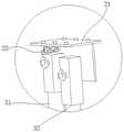
图3是本发明实施例中一种无人机伸缩悬臂测量装置中A处结构的放大示意图;3 is an enlarged schematic view of the structure at A in an unmanned aerial vehicle telescopic cantilever measurement device according to an embodiment of the present invention;
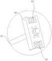
图4是本发明实施例中一种无人机伸缩悬臂测量装置中B处结构的放大示意图;4 is an enlarged schematic view of the structure at B in an unmanned aerial vehicle telescopic cantilever measurement device in an embodiment of the present invention;
图5是本发明实施例中一种无人机伸缩悬臂测量装置中C处结构的放大示意图;5 is an enlarged schematic view of the structure at C in an unmanned aerial vehicle telescopic cantilever measuring device in an embodiment of the present invention;
图中,In the figure,
1、无人机;1. UAV;
2、衔接座;21、法兰板;22、扭力弹簧;2. Connection seat; 21. Flange plate; 22. Torsion spring;
3、第一连杆组件;31、第一连接杆;32、第二连接杆;3. The first connecting rod assembly; 31. The first connecting rod; 32. The second connecting rod;
4、第二连杆组件;41、第三连接杆;42、第四连接杆;43、拉力弹簧;44、环扣4. The second connecting rod assembly; 41, the third connecting rod; 42, the fourth connecting rod; 43, the tension spring; 44, the ring buckle
5、第一转接座;5. The first adapter;
6、第二转接座;6. The second adapter;
7、检测装置;7. Detection device;
8、支撑机构;81、第五连接杆;82、安装座;83、永磁滚动珠。8. Supporting mechanism; 81. Fifth connecting rod; 82. Mounting seat; 83. Permanent magnet rolling ball.
具体实施方式Detailed ways
下面结合附图和实施例,对本发明的具体实施方式作进一步详细描述。以下实施例用于说明本发明,但不用来限制本发明的范围。The specific embodiments of the present invention will be described in further detail below with reference to the accompanying drawings and embodiments. The following examples are intended to illustrate the present invention, but not to limit the scope of the present invention.
在本申请的描述中,需要理解的是,术语“中心”、“上”、“下”、“前”、“后”、“左”、“右”、“竖直”、“水平”、“顶”、“底”、“内”、“外”等指示的方位或位置关系为基于附图所示的方位或位置关系,仅是为了便于描述本申请和简化描述,而不是指示或暗示所指的装置或元件必须具有特定的方位、以特定的方位构造和操作,因此不能理解为对本申请的限制。In the description of this application, it should be understood that the terms "center", "upper", "lower", "front", "rear", "left", "right", "vertical", "horizontal", The orientation or positional relationship indicated by "top", "bottom", "inner", "outer", etc. is based on the orientation or positional relationship shown in the drawings, and is only for the convenience of describing the present application and simplifying the description, rather than indicating or implying The device or element referred to must have a particular orientation, be constructed and operate in a particular orientation, and therefore should not be construed as a limitation of the present application.
术语“第一”、“第二”仅用于描述目的,而不能理解为指示或暗示相对重要性或者隐含指明所指示的技术特征的数量。由此,限定有“第一”、“第二”的特征可以明示或者隐含地包括一个或者更多个该特征。在本申请的描述中,除非另有说明,“多个”的含义是两个或两个以上。The terms "first" and "second" are only used for descriptive purposes, and should not be construed as indicating or implying relative importance or implicitly indicating the number of technical features indicated. Thus, a feature defined as "first" or "second" may expressly or implicitly include one or more of that feature. In the description of this application, unless stated otherwise, "plurality" means two or more.
在本申请的描述中,需要说明的是,除非另有明确的规定和限定,术语“安装”、“相连”、“连接”应做广义理解,例如,可以是固定连接,也可以是可拆卸连接,或一体地连接;可以是机械连接,也可以是电连接;可以是直接相连,也可以通过中间媒介间接相连,可以是两个元件内部的连通。对于本领域的普通技术人员而言,可以具体情况理解上述术语在本申请中的具体含义。In the description of this application, it should be noted that, unless otherwise expressly specified and limited, the terms "installed", "connected" and "connected" should be understood in a broad sense, for example, it may be a fixed connection or a detachable connection Connection, or integral connection; can be mechanical connection, can also be electrical connection; can be directly connected, can also be indirectly connected through an intermediate medium, can be internal communication between two elements. For those of ordinary skill in the art, the specific meanings of the above terms in this application can be understood in specific situations.
本发明提供了一种无人机伸缩悬臂测量装置,应用于无人机1中,该装置包括衔接座、伸缩悬臂机构、转接座、支撑机构和检测装置。The present invention provides an unmanned aerial vehicle telescopic cantilever measuring device, which is applied to the unmanned aerial vehicle 1, and the device includes a joint seat, a telescopic cantilever mechanism, an adapter seat, a support mechanism and a detection device.
衔接座2,固定连接于所述无人机1;The connecting
伸缩悬臂机构,铰接于所述衔接座2;The telescopic cantilever mechanism is hinged to the connecting
转接座,铰接于所述伸缩悬臂机构;an adapter seat, hinged to the telescopic cantilever mechanism;
支撑机构8,固定连接于所述转接座,所述支撑机构8用于随着所述伸缩悬臂机构和转接座进行摆动;a
检测装置7,固定连接于所述支撑机构8;The
所述伸缩悬臂机构用于带动所述支撑机构8进行伸展或回缩。The telescopic cantilever mechanism is used to drive the
本申请一些实施例中,所述伸缩悬臂机构包括第一连杆组件3、第二连杆组件4和弹性组件;第一连杆组件3一端铰接于所述衔接座2,另一端铰接于所述转接座;第二连杆组件4两端铰接于所述转接座;弹性组件一端固定连接于所述第一连杆组件3,另一端滑动连接于所述第二连杆组件4,所述弹性组件用于使所述第二连杆组件4伸缩。In some embodiments of the present application, the telescopic cantilever mechanism includes a first link assembly 3, a second link assembly 4 and an elastic assembly; one end of the first link assembly 3 is hinged to the connecting
本申请一些实施例中,所述转接座包括第一转接座5和第二转接座6;第一转接座5铰接于所述第一连杆组件3和所述第二连杆组件4,所述第一转接座5用于使所述第一连杆组件3和所述第二连杆组件4以所述第一转接座5为中心进行摆动;第二转接座6一端铰接于所述第二连杆组件4,另一端固定连接于所述支撑机构8,所述第二转接座6用于带动所述支撑机构8随所述第二连杆组件4摆动。In some embodiments of the present application, the adapter includes a first adapter 5 and a
本申请一些实施例中,所述第一连杆组件3包括第一连接杆31和第二连接杆32;第一连接杆31一端铰接于所述衔接座2,另一端铰接于所述第一转接座5;第二连接杆32一端铰接于所述衔接座2,另一端铰接于所述第一转接座5,所述第二连接杆32上固定连接于所述弹性组件。In some embodiments of the present application, the first connecting rod assembly 3 includes a first connecting
本申请一些实施例中,所述第二连杆组件4包括第三连接杆41和第四连接杆42;第三连接杆41一端铰接于所述第一转接座5,另一端铰接于所述第二转接座6,所述第三连接杆41上开设有滑槽;第四连接杆42一端铰接于所述第一转接座5,另一端铰接于所述第二转接座6。In some embodiments of the present application, the second connecting rod assembly 4 includes a third connecting
本申请一些实施例中,所述弹性组件包括拉力弹簧43和环扣44;拉力弹簧43一端固定连接于所述第二连接杆32;环扣44滑动设置于所述滑槽中,使得环扣44在合理的行程范围内滑动,环扣44为呈“D”形的结构,所述拉力弹簧43另一端挂接于所述环扣44,所述环扣44用于带动所述拉力弹簧43在所述滑槽内滑动。拉力弹簧43使第二连杆组件4具有伸缩的弹性。In some embodiments of the present application, the elastic component includes a
本申请一些实施例中,所述衔接座2包括法兰板21和扭力弹簧22;法兰板21固定连接于所述无人机1,所述法兰板21铰接于所述第一连接杆31和所述第二连接杆32;扭力弹簧22抵接于所述法兰板21和所述第一连接杆31之间,使得第一连接杆31具有倾斜向前的弹性应力。In some embodiments of the present application, the connecting
本申请一些实施例中,所述支撑机构8还包括永磁滚动珠83,所述永磁滚动珠83设置于所述安装座82两侧,所述永磁滚动珠83用于带动所述安装座82在管壁上滑动,从而使所述安装座82与所述检测装置7之间存在间隙。In some embodiments of the present application, the
本申请一些实施例中,所述检测装置7包括电磁超声探头,所述电磁超声探头固定连接于所述安装座82上,所述电磁超声探头用于对管壁厚度进行测量。In some embodiments of the present application, the
通过应用以上技术方案,本申请中无人机1通过法兰板21和扭力弹簧22带动第一连接杆31和第二连接杆32摆动,第一连接杆31和第二连接杆32通过第一转接座5带动第三连接杆41和第四连接杆42摆动,且第二连接杆32通过拉力弹簧43在滑槽里滑动,从而带动第三连接杆41,第三连接杆41和第四连接杆42通过第二转接座6带动安装座82滑动,安装座82上的永磁滚动珠83滑动在管道内壁上,使得电磁超声探头与管道壁面存在间隙。伸缩悬臂机构伸长时,扭力弹簧22被处于被压缩状态,拉伸弹簧处于被拉长状态。当无人机1完成缺陷或管道检测时,无人机1远离壁面,通过无人机1的拖拽使得探头与壁面分离。由于扭力弹簧22与拉伸弹簧分别处于压缩与拉伸状态,由弹簧的弹力使得伸缩悬臂机构收缩。By applying the above technical solutions, in this application, the UAV 1 drives the first connecting
伸缩悬臂机构和支撑机构8可伸缩并对探头与壁面的触碰起到一定的缓冲作用。此外,采用电磁超声探头对管壁进行测厚时,测量探头磁性较大易与管壁磁吸附,吸附后需用较大拔起力使探头与管壁分离才能进行下一点的测量,因而需要对吸附力进行控制避免其影响无人机1的飞行,本发明安装带永磁性滚动珠的连接结构并通过其前端的永磁滚动珠83结构使笔式探头与测量壁面保持一定的间隙距离,可有效避免直接磁吸附,使吸附力控制在一定合理的范围内,使得机械臂前置的电磁超声探头可随无人机1的拖动在被测管壁上移动,完成测厚数据采集。The telescopic cantilever mechanism and the
根据本申请的第一构思,改进了无人机1悬臂的转动结构,伸缩悬臂机构通过衔接座2连接无人机1,伸缩悬臂机构包括第一连杆组件3、第二连杆组件4和弹性组件,第一连杆组件3一端铰接于所述衔接座2,另一端铰接于所述转接座;第二连杆组件4两端铰接于所述转接座;弹性组件一端固定连接于所述第一连杆组件3,另一端滑动连接于所述第二连杆组件4,所述弹性组件用于使所述第二连杆组件4伸缩。通过扭力弹簧22、拉伸弹簧和多个连杆组成的伸缩结构实现测厚过程中机械臂的柔性伸缩过程,解决因接触壁面测厚中对飞行器的位置和姿态控制精度要求过高的问题。According to the first concept of the present application, the rotating structure of the cantilever of the unmanned aerial vehicle 1 is improved, the telescopic cantilever mechanism is connected to the unmanned aerial vehicle 1 through the
根据本申请的第二构思,改进了无人机1与管壁的接触结构,支撑机构8连接伸缩悬臂机构,所述支撑机构8包括第五连接杆81、安装座82和永磁滚动珠83,第五连接杆81一端固定连接于所述第二转接座6;安装座82固定连接于所述第五连接杆81的另一端;永磁滚动珠83设置于所述安装座82两侧,所述永磁滚动珠83用于带动所述安装座82在管壁上滑动,从而使所述安装座82与所述检测装置7之间存在间隙。通过前端的永磁滚动珠83结构使笔式电磁超声探头与测量壁面保持一定的间隙距离,可有效避免直接磁吸附,使吸附力控制在一定合理的范围内,使得支撑机构8前置的电磁超声探头可随无人机1的拖动在被测管壁上移动,完成测厚数据采集。According to the second concept of the present application, the contact structure of the UAV 1 and the pipe wall is improved, the
以上所述仅是本发明的优选实施方式,应当指出,对于本技术领域的普通技术人员来说,在不脱离本发明技术原理的前提下,还可以做出若干改进和替换,这些改进和替换也应视为本发明的保护范围。The above are only the preferred embodiments of the present invention. It should be pointed out that for those skilled in the art, without departing from the technical principle of the present invention, several improvements and replacements can be made. These improvements and replacements It should also be regarded as the protection scope of the present invention.
Claims (10)
Translated fromChinesePriority Applications (1)
| Application Number | Priority Date | Filing Date | Title |
|---|---|---|---|
| CN202210256127.4ACN114643596A (en) | 2022-03-15 | 2022-03-15 | Unmanned aerial vehicle telescopic cantilever measuring device |
Applications Claiming Priority (1)
| Application Number | Priority Date | Filing Date | Title |
|---|---|---|---|
| CN202210256127.4ACN114643596A (en) | 2022-03-15 | 2022-03-15 | Unmanned aerial vehicle telescopic cantilever measuring device |
Publications (1)
| Publication Number | Publication Date |
|---|---|
| CN114643596Atrue CN114643596A (en) | 2022-06-21 |
Family
ID=81994462
Family Applications (1)
| Application Number | Title | Priority Date | Filing Date |
|---|---|---|---|
| CN202210256127.4APendingCN114643596A (en) | 2022-03-15 | 2022-03-15 | Unmanned aerial vehicle telescopic cantilever measuring device |
Country Status (1)
| Country | Link |
|---|---|
| CN (1) | CN114643596A (en) |
Cited By (2)
| Publication number | Priority date | Publication date | Assignee | Title |
|---|---|---|---|---|
| CN116106417A (en)* | 2023-04-07 | 2023-05-12 | 沙河市津海特钢有限公司 | A equipment for gas cylinder ultrasonic flaw detection |
| WO2024123272A1 (en)* | 2022-12-09 | 2024-06-13 | Dna Marin Yazilim Gemi Muhendisligi Sanayi Ve Ticaret Limited Sirketi | An unmanned aerial vehicle |
Citations (11)
| Publication number | Priority date | Publication date | Assignee | Title |
|---|---|---|---|---|
| FR2923353A1 (en)* | 2007-11-12 | 2009-05-15 | Signalisation Moderne Autorout | Mowing, clearing or pruning machine for use with tractor, has balance beam and articulated jib forming telescopic articulated arm, inclination head mounted on end of balance beam, and protecting covers protecting flexible pipeline |
| DE102010017608A1 (en)* | 2010-06-25 | 2011-12-29 | Fiedler Maschinenbau Und Technikvertrieb Gmbh | Device carrier and bracket combination for e.g. road sweeper installed at carrier vehicle to remove ground vegetation from road, has inclination cylinder hinged at telescopic arm end, and protection device arranged at cleaning head |
| CN107092087A (en)* | 2017-06-27 | 2017-08-25 | 苏州奥特科然医疗科技有限公司 | A kind of surgical operation microscope support |
| US20180361462A1 (en)* | 2014-07-09 | 2018-12-20 | The Boeing Company | Metrology-Based System for Operating a Flexible Manufacturing System |
| US20190366426A1 (en)* | 2017-07-19 | 2019-12-05 | Anhui University of Science and Technology | Multi-arm hanging rail type casting cleaning robot |
| CN111927720A (en)* | 2020-09-17 | 2020-11-13 | 中国农业大学 | Adsorption moving device for ultrasonic nondestructive testing of wind driven generator tower body array |
| CN112692870A (en)* | 2020-12-28 | 2021-04-23 | 易程融创信息科技有限公司 | Mechanical arm |
| CN113320698A (en)* | 2021-07-09 | 2021-08-31 | 浙江星空通用航空科技有限公司 | Telescopic long and short mechanical operating arm for unmanned helicopter |
| CN113415405A (en)* | 2021-07-30 | 2021-09-21 | 天津爱思达新材料科技有限公司 | Unmanned aerial vehicle's horn automatic control device and unmanned aerial vehicle |
| CN215395313U (en)* | 2020-12-28 | 2022-01-04 | 易程融创信息科技有限公司 | Mechanical arm |
| CN215903518U (en)* | 2021-09-23 | 2022-02-25 | 苏州澳钍智能科技有限公司 | Multi-connecting-rod swinging mechanical arm |
- 2022
- 2022-03-15CNCN202210256127.4Apatent/CN114643596A/enactivePending
Patent Citations (11)
| Publication number | Priority date | Publication date | Assignee | Title |
|---|---|---|---|---|
| FR2923353A1 (en)* | 2007-11-12 | 2009-05-15 | Signalisation Moderne Autorout | Mowing, clearing or pruning machine for use with tractor, has balance beam and articulated jib forming telescopic articulated arm, inclination head mounted on end of balance beam, and protecting covers protecting flexible pipeline |
| DE102010017608A1 (en)* | 2010-06-25 | 2011-12-29 | Fiedler Maschinenbau Und Technikvertrieb Gmbh | Device carrier and bracket combination for e.g. road sweeper installed at carrier vehicle to remove ground vegetation from road, has inclination cylinder hinged at telescopic arm end, and protection device arranged at cleaning head |
| US20180361462A1 (en)* | 2014-07-09 | 2018-12-20 | The Boeing Company | Metrology-Based System for Operating a Flexible Manufacturing System |
| CN107092087A (en)* | 2017-06-27 | 2017-08-25 | 苏州奥特科然医疗科技有限公司 | A kind of surgical operation microscope support |
| US20190366426A1 (en)* | 2017-07-19 | 2019-12-05 | Anhui University of Science and Technology | Multi-arm hanging rail type casting cleaning robot |
| CN111927720A (en)* | 2020-09-17 | 2020-11-13 | 中国农业大学 | Adsorption moving device for ultrasonic nondestructive testing of wind driven generator tower body array |
| CN112692870A (en)* | 2020-12-28 | 2021-04-23 | 易程融创信息科技有限公司 | Mechanical arm |
| CN215395313U (en)* | 2020-12-28 | 2022-01-04 | 易程融创信息科技有限公司 | Mechanical arm |
| CN113320698A (en)* | 2021-07-09 | 2021-08-31 | 浙江星空通用航空科技有限公司 | Telescopic long and short mechanical operating arm for unmanned helicopter |
| CN113415405A (en)* | 2021-07-30 | 2021-09-21 | 天津爱思达新材料科技有限公司 | Unmanned aerial vehicle's horn automatic control device and unmanned aerial vehicle |
| CN215903518U (en)* | 2021-09-23 | 2022-02-25 | 苏州澳钍智能科技有限公司 | Multi-connecting-rod swinging mechanical arm |
Cited By (3)
| Publication number | Priority date | Publication date | Assignee | Title |
|---|---|---|---|---|
| WO2024123272A1 (en)* | 2022-12-09 | 2024-06-13 | Dna Marin Yazilim Gemi Muhendisligi Sanayi Ve Ticaret Limited Sirketi | An unmanned aerial vehicle |
| CN116106417A (en)* | 2023-04-07 | 2023-05-12 | 沙河市津海特钢有限公司 | A equipment for gas cylinder ultrasonic flaw detection |
| CN116106417B (en)* | 2023-04-07 | 2023-07-14 | 沙河市津海特钢有限公司 | A equipment for gas cylinder ultrasonic flaw detection |
Similar Documents
| Publication | Publication Date | Title |
|---|---|---|
| CN114643596A (en) | Unmanned aerial vehicle telescopic cantilever measuring device | |
| CN104565675B (en) | Pipeline inspection robot | |
| CN102759564B (en) | A kind of variable diameter pipe external magnetic memory detection device | |
| CN110596578A (en) | A Non-contact Measuring Device for GIS Equipment Deformation | |
| CN106226031B (en) | Experimental device for be used for granule in viscous medium and wall collision experiment | |
| CN204101509U (en) | Contactless leakage of fault detecting probe rod of hollow axle | |
| CN204228125U (en) | A kind of thickness measuring detects auxiliary operating lever | |
| CN102879458B (en) | Damage detector based on piezomagnetic effect | |
| CN107367331A (en) | A kind of continuous measuring device of Ethylene Cracking Furnace Tubes temperature | |
| CN109030635A (en) | A kind of probe mechanism of reactor pressure vessel kingbolt ultrasonic inspection apparatus | |
| CN104535037A (en) | Measurement device for shape of inner wall of oil and gas pipe | |
| CN113404975B (en) | Detection equipment for internal state of water delivery pipeline | |
| CN217673245U (en) | A UAV telescopic cantilever measuring device | |
| CN202794107U (en) | Variable diameter pipe outside magnetic memory detection device | |
| CN109360670A (en) | A multifunctional detection device for self-adaptive centering of nuclear fuel assemblies | |
| CN104976606B (en) | Expansion indicator with on-line monitoring function | |
| CN204881594U (en) | Oil and natural gas pipe inner wall shape measuring equipment | |
| CN103018002B (en) | Testing device and method for measuring wind drag of automobile model | |
| CN117849165A (en) | A kind of oil pipe flaw detection device at well repair operation site | |
| CN211122667U (en) | An adjustable pipeline magnetic flux leakage detection device | |
| CN109387176A (en) | A kind of aircraft rudder surface angle displacement measuring device | |
| CN117410055A (en) | A system for monitoring and adjusting the three-dimensional attitude of superconducting magnets | |
| CN209784259U (en) | Automatic wall-climbing far-field vortex and video detection system for water wall tube of power station boiler | |
| CN114440806B (en) | Automatic measurement method and device for pressure pipe sagging | |
| CN203534497U (en) | Connecting rod detecting machine |
Legal Events
| Date | Code | Title | Description |
|---|---|---|---|
| PB01 | Publication | ||
| PB01 | Publication | ||
| SE01 | Entry into force of request for substantive examination | ||
| SE01 | Entry into force of request for substantive examination |