CN114643479A - Precision lathe based on comprehensive processing of body-building dumbbell rod body - Google Patents
Precision lathe based on comprehensive processing of body-building dumbbell rod bodyDownload PDFInfo
- Publication number
- CN114643479A CN114643479ACN202210541081.0ACN202210541081ACN114643479ACN 114643479 ACN114643479 ACN 114643479ACN 202210541081 ACN202210541081 ACN 202210541081ACN 114643479 ACN114643479 ACN 114643479A
- Authority
- CN
- China
- Prior art keywords
- lathe
- turntable
- fixedly installed
- electric
- shaft
- Prior art date
- Legal status (The legal status is an assumption and is not a legal conclusion. Google has not performed a legal analysis and makes no representation as to the accuracy of the status listed.)
- Granted
Links
Images


Classifications
- B—PERFORMING OPERATIONS; TRANSPORTING
- B23—MACHINE TOOLS; METAL-WORKING NOT OTHERWISE PROVIDED FOR
- B23P—METAL-WORKING NOT OTHERWISE PROVIDED FOR; COMBINED OPERATIONS; UNIVERSAL MACHINE TOOLS
- B23P23/00—Machines or arrangements of machines for performing specified combinations of different metal-working operations not covered by a single other subclass
- B23P23/04—Machines or arrangements of machines for performing specified combinations of different metal-working operations not covered by a single other subclass for both machining and other metal-working operations
- Y—GENERAL TAGGING OF NEW TECHNOLOGICAL DEVELOPMENTS; GENERAL TAGGING OF CROSS-SECTIONAL TECHNOLOGIES SPANNING OVER SEVERAL SECTIONS OF THE IPC; TECHNICAL SUBJECTS COVERED BY FORMER USPC CROSS-REFERENCE ART COLLECTIONS [XRACs] AND DIGESTS
- Y02—TECHNOLOGIES OR APPLICATIONS FOR MITIGATION OR ADAPTATION AGAINST CLIMATE CHANGE
- Y02P—CLIMATE CHANGE MITIGATION TECHNOLOGIES IN THE PRODUCTION OR PROCESSING OF GOODS
- Y02P70/00—Climate change mitigation technologies in the production process for final industrial or consumer products
- Y02P70/10—Greenhouse gas [GHG] capture, material saving, heat recovery or other energy efficient measures, e.g. motor control, characterised by manufacturing processes, e.g. for rolling metal or metal working
Landscapes
- Physics & Mathematics (AREA)
- Optics & Photonics (AREA)
- Engineering & Computer Science (AREA)
- Mechanical Engineering (AREA)
- Turning (AREA)
- Laser Beam Processing (AREA)
Abstract
Translated fromChinese
Description
Translated fromChinese技术领域technical field
本发明涉及金属加工技术领域,具体为一种基于健身哑铃杆身全面加工的精密车床。The invention relates to the technical field of metal processing, in particular to a precision lathe based on comprehensive processing of fitness dumbbell shafts.
背景技术Background technique
为了提高复杂异型产品的加工效率和加工精度,工艺人员一直在寻求更为高效精密的加工工艺方法。车铣复合加工设备的出现为提高航空航天零件的加工精度和效率提供了一种有效解决方案。加工效率与精度是金属加工领域追求的永恒目标。随着数控技术、计算机技术、机床技术以及加工工艺技术的不断发展,传统的加工理念已不能满足人们对加工速度、效率和精度的要求。在这样的背景下,复合加工技术应运而生。一般来说,复合加工是指在一台加工设备上能够完成不同工序或者不同工艺方法的加工技术的总称。复合加工技术主要表现为2种不同的类型,一种是以能量或运动方式为基础的不同加工方法的复合;另一种是以工序集中原则为基础的、以机械加工工艺为主的复合,车铣复合加工是近年来该领域发展最为迅速的加工方式之一。In order to improve the processing efficiency and processing accuracy of complex special-shaped products, technicians have been seeking more efficient and precise processing methods. The emergence of turn-milling composite machining equipment provides an effective solution for improving the machining accuracy and efficiency of aerospace parts. Processing efficiency and precision are the eternal goals pursued in the field of metal processing. With the continuous development of numerical control technology, computer technology, machine tool technology and processing technology, traditional processing concepts can no longer meet people's requirements for processing speed, efficiency and precision. In this context, composite processing technology came into being. Generally speaking, composite processing refers to the general term for processing technologies that can complete different processes or different process methods on one processing equipment. Composite processing technology is mainly manifested in two different types, one is a composite of different processing methods based on energy or motion; the other is a composite based on the principle of process concentration and mainly based on mechanical processing technology. Turn-milling machining is one of the most rapidly developing machining methods in this field in recent years.
如申请号为CN202011338131.2的一种多工位多轴车铣复合加工中心,包括工作台,工作台的顶部设置有升降机构以及位于升降机构一侧的夹具机构,升降机构由竖板、第一支撑板、第一步进电机、第一丝杆、第一传动块和第一支撑杆组成。该发明通过设置两个旋转卡具,当对其中一个旋转卡具上夹持的工件进行加工时,工作人员可以将另一个旋转卡具上加工好的工件取下或装入未加工的工件,能够减少工件更换需要耗费的停机时间,进而能够提高该车铣复合加工中心对工件的加工效率,通过第二步进电机带动第二丝杆转动能够使第二传动块带动液压缸上升或下降,通过液压缸和推板能够推动其中一个方杆带动对应的刀具伸出,从而实现加工过程中的快速换刀。For example, a multi-station multi-axis turning-milling compound machining center with application number CN202011338131.2 includes a worktable, a lifting mechanism and a clamp mechanism located on one side of the lifting mechanism are arranged on the top of the worktable, and the lifting mechanism is composed of a vertical plate, a first A support plate, a first step motor, a first screw rod, a first transmission block and a first support rod are composed. In this invention, by setting two rotary fixtures, when processing the workpiece clamped on one of the rotary fixtures, the worker can take off the processed workpiece on the other rotary fixture or load the unprocessed workpiece, The downtime required for workpiece replacement can be reduced, and the machining efficiency of the turn-milling compound machining center for workpieces can be improved. The second stepper motor drives the second screw rod to rotate, so that the second transmission block drives the hydraulic cylinder to rise or fall. The hydraulic cylinder and the push plate can push one of the square rods to drive the corresponding tool to extend, so as to realize quick tool change during the machining process.
而上述的技术方案,在具体实施时,由于本方案针对长金属杆进行加工时,由于此金属杆应用于健身中杠铃的装配,在健身锻炼时,为了防止手部持握使滑落,会在金属杆上车出诸多细纹,而在现在的设置对细长的金属杆表面加工时,加工面积小,所以不易于加工。When the above technical solution is specifically implemented, since this solution is aimed at processing a long metal rod, and because the metal rod is used in the assembly of barbells in fitness, during fitness exercise, in order to prevent the hand from being held and slipped, it will be There are many fine lines on the metal rod, and when the surface of the slender metal rod is processed by the current setting, the processing area is small, so it is not easy to process.
发明内容SUMMARY OF THE INVENTION
针对现有技术的不足,本发明提供了一种基于健身哑铃杆身全面加工的精密车床,解决了由于此金属杆应用于健身中杠铃的装配,在健身锻炼时,为了防止手部持握使滑落,会在金属杆上车出诸多细纹,而在现在的设置对细长的金属杆表面加工时,加工面积小,所以不易于加工的问题。In view of the deficiencies of the prior art, the present invention provides a precision lathe based on the comprehensive processing of the body of the fitness dumbbell, which solves the problem that because the metal rod is used in the assembly of the barbell in fitness, during fitness exercise, in order to prevent the hand from holding If it slips off, there will be many fine lines on the metal rod. However, when the surface of the slender metal rod is processed by the current setting, the processing area is small, so it is not easy to process.
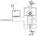
为实现以上目的,本发明通过以下技术方案予以实现:一种基于健身哑铃杆身全面加工的精密车床,包括车床工作台,所述车床工作台上端表面固定安装有车床防护罩,且所述车床防护罩为上端开口敞开式,所述车床防护罩两侧内壁上均固定安装有两个第一电动滑轨,两个所述第一电动滑轨上均滑动安装有两个纹路车槽组件,所述车床工作台上端表面固定安装有杆身旋转组件,所述车床工作台两端均一体化连接有两个送料组件安装台,两个所述送料组件安装台上均固定安装有若干第二电动滑轨,每两个一组的所述第二电动滑轨上滑动安装有哑铃片头送料组件,所述车床工作台前端固定连接有输料箱,所述输料箱内部开设有输料槽,所述输料槽内部设置有输料传送带,所述输料传送带外侧表面两端均设置有若干对称设置的杆身固定台,所述车床防护罩上方表面两端均固定安装有两个激光焊接机。In order to achieve the above purpose, the present invention is achieved through the following technical solutions: a precision lathe based on comprehensive processing of fitness dumbbell shafts, including a lathe workbench, a lathe protective cover is fixedly installed on the upper end surface of the lathe workbench, and the lathe The protective cover is of an open-top type, two first electric sliding rails are fixedly installed on the inner walls of both sides of the lathe protective cover, and two grooved groove assemblies are slidably installed on the two first electric sliding rails. The upper surface of the lathe worktable is fixedly installed with a rod body rotating assembly, both ends of the lathe worktable are integrally connected with two feeding assembly mounting platforms, and a plurality of second feeding assembly mounting platforms are fixedly installed on both of the two feeding assembly mounting platforms. Electric slide rails, each two sets of the second electric slide rails are slidably installed with dumbbell head feeding assemblies, the front end of the lathe table is fixedly connected with a feeding box, and a feeding trough is opened inside the feeding box , the inside of the feeding chute is provided with a feeding conveyor belt, both ends of the outer surface of the feeding conveyor belt are provided with a number of symmetrically arranged rod body fixing platforms, and both ends of the upper surface of the lathe protective cover are fixedly installed with two lasers Welding machine.
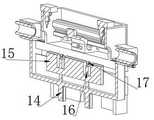
作为优选的,所述输料箱上端表面固定安装有电气控制面板,所述车床工作台下端固定安装有两个升降气缸,两个所述升降气缸的输出端上固定连接有升料台,所述升料台纵向滑动设置在车床工作台内,所述升料台上方表面两端均设置有两个杆身支撑台,两个所述杆身支撑台上端均转动安装有两个杆身旋转从动轮,所述输料槽开设至升料台一侧。Preferably, an electrical control panel is fixedly installed on the upper surface of the feeding box, two lifting cylinders are fixedly installed at the lower end of the lathe worktable, and a lifting table is fixedly connected to the output ends of the two lifting cylinders, so The lifting table is longitudinally slidable in the lathe worktable, two rod body support platforms are arranged on both ends of the upper surface of the lifting table, and two rod body rotations are installed on the upper ends of the two rod body support platforms. The driven wheel, the feeding trough is opened to one side of the lifting platform.
作为优选的,所述车床工作台内且位于升料台另一侧开设有成品出料槽,所述成品出料槽内下端表面开设有两个截料杆滑槽,两个所述截料杆滑槽底端均固定安装有两个驱动气缸,两个所述驱动气缸的输出端上固定连接有截料杆,所述截料杆呈U型。Preferably, a finished product discharge chute is provided in the lathe worktable and on the other side of the lifting table, and two cutting rod chutes are provided on the inner and lower end surface of the finished product discharge chute. Two driving cylinders are fixedly installed at the bottom ends of the rod chute, and cutting rods are fixedly connected to the output ends of the two driving cylinders, and the cutting rods are U-shaped.
作为优选的,所述纹路车槽组件包括:电动滑轨连接底座、电动旋转底座、第一电机、直角传动箱、电动旋转杆、驱动旋转轴、翻转板、车纹轮刀、轮刀转盘、旋转轴转盘和轮刀皮带,所述电动滑轨连接底座滑动设置在第一电动滑轨上,所述电动滑轨连接底座前端固定安装有电动旋转底座,所述电动旋转底座前端转动安装有第一电机前端固定安装有直角传动箱,所述直角传动箱上转动设置有驱动旋转轴,所述直角传动箱一端固定安装有电动旋转杆,所述电动旋转杆上转动安装有翻转板,所述翻转板一侧表面转动安装有车纹轮刀,所述车纹轮刀一端同轴固定连接有轮刀转盘,所述轮刀转盘上套设有若干轮刀皮带,所述轮刀皮带内一端还套设有旋转轴转盘,所述旋转轴转盘与驱动旋转轴同轴固定连接。Preferably, the grooved groove assembly includes: an electric sliding rail connection base, an electric rotating base, a first motor, a right-angle transmission box, an electric rotating rod, a driving rotating shaft, a turning plate, a turning wheel, a wheel cutter turntable, The rotating shaft turntable and the wheel cutter belt, the electric slide rail connection base is slidably arranged on the first electric slide rail, the front end of the electric slide rail connection base is fixedly installed with the electric rotary base, and the front end of the electric rotary base is rotatably installed with the first electric rotary base. A right-angle transmission box is fixedly installed at the front end of the motor, a drive rotating shaft is rotatably arranged on the right-angle transmission box, an electric rotating rod is fixedly installed at one end of the right-angle transmission box, and a turning plate is rotated and installed on the electric rotating rod, One side surface of the turning plate is rotatably installed with a turning wheel cutter, one end of the turning wheel cutter is coaxially fixedly connected with a wheel cutter turntable, a plurality of wheel cutter belts are sleeved on the wheel cutter turntable, and the inner end of the wheel cutter belt is A rotary shaft turntable is also sleeved, and the rotary shaft turntable is coaxially and fixedly connected with the driving rotary shaft.
作为优选的,所述车纹轮刀上设置有若干等距分布的切刀。Preferably, a plurality of equidistantly distributed cutting knives are provided on the grooving wheel cutter.
作为优选的,所述直角传动箱包括:转动箱外壳、第一锥齿轮、第二锥齿轮和第一电机连接轴,所述转动箱外壳内设置有第一锥齿轮,所述第一锥齿轮与驱动旋转轴同轴固定连接,所述第一锥齿轮一侧啮合连接第二锥齿轮,所述第二锥齿轮后端同轴固定连接有第一电机连接轴。Preferably, the right-angle transmission case includes: a rotating case casing, a first bevel gear, a second bevel gear and a first motor connecting shaft, a first bevel gear is arranged in the rotating case casing, and the first bevel gear It is coaxially and fixedly connected with the driving rotating shaft, one side of the first bevel gear is meshed with the second bevel gear, and the rear end of the second bevel gear is coaxially and fixedly connected with a first motor connecting shaft.
作为优选的,所述第一电机连接轴与第一电机的输出轴同轴固定连接。Preferably, the first motor connecting shaft is coaxially and fixedly connected to the output shaft of the first motor.
作为优选的,所述杆身旋转组件包括:旋转组件外壳、驱动辊支架、驱动辊、驱动辊转盘、第二电机、第二电机转盘和驱动辊皮带,所述旋转组件外壳上端表面固定安装有第二电机,所述旋转组件外壳两侧内壁上均一体化连接有两个驱动辊支架,两个所述驱动辊支架上均转动安装有亮两个驱动辊,其中一个所述驱动辊一端同轴固定连接有驱动辊转盘,所述驱动辊转盘上转动套设有驱动辊皮带,所述驱动辊皮带内还套设有第二电机转盘,所述第二电机转盘后端与第二电机的输出轴同轴固定连接。Preferably, the shaft rotating assembly includes: a rotating assembly casing, a driving roller bracket, a driving roller, a driving roller turntable, a second motor, a second motor turntable and a driving roller belt, and the upper end surface of the rotating assembly casing is fixedly mounted with a For the second motor, two driving roller brackets are integrally connected to the inner walls on both sides of the rotating assembly shell, and two driving rollers are rotatably installed on both of the two driving roller brackets, one of the driving rollers has one end at the same end. The shaft is fixedly connected with a driving roller turntable, a driving roller belt is rotatably sleeved on the driving roller turntable, and a second motor turntable is also sleeved inside the driving roller belt, and the rear end of the second motor turntable is connected with the second motor. The output shaft is fixed coaxially.
作为优选的,所述哑铃片头送料组件包括:送料组件外壳、固定圆框、两段式电动轴、半圆框、第三电动滑轨、出料槽下底板和安装头固定圈,所述送料组件外壳上固定安装有固定圆框,所述固定圆框上端固定安装有两段式电动轴,所述两段式电动轴上转动安装有两个半圆框,两个所述半圆框内壁上固定安装有若干第三电动滑轨,固定在同一半圆框内的所述第三电动滑轨上滑动安装有安装头固定圈。Preferably, the dumbbell film head feeding assembly includes: a feeding assembly shell, a fixed round frame, a two-segment electric shaft, a semi-circular frame, a third electric sliding rail, a lower bottom plate of the discharge chute, and a mounting head fixing ring. The feeding assembly A fixed round frame is fixedly installed on the casing, a two-stage electric shaft is fixedly installed on the upper end of the fixed round frame, two semi-circular frames are rotatably installed on the two-stage electric shaft, and the inner walls of the two semi-circular frames are fixedly installed There are several third electric sliding rails, and a mounting head fixing ring is slidably installed on the third electric sliding rails fixed in the same semicircular frame.
作为优选的,所述安装头固定圈内圈一体化安装有固定橡胶圈,所述送料组件外壳前端表面且位于固定圆框下方固定安装有两个出料槽下底板。Preferably, a fixed rubber ring is integrally installed on the inner ring of the fixing head of the mounting head, and two lower bottom plates of the discharge chute are fixedly installed on the front end surface of the outer casing of the feeding assembly and below the fixed circular frame.
有益效果beneficial effect
本发明提供了一种基于健身哑铃杆身全面加工的精密车床。具备以下有益效果:The invention provides a precision lathe based on comprehensive processing of fitness dumbbell shafts. Has the following beneficial effects:
本方案根据上述背景技术中提出的由于此金属杆应用于健身中杠铃的装配,在健身锻炼时,为了防止手部持握使滑落,会在金属杆上车出诸多细纹,而在现在的设置对细长的金属杆表面加工时,加工面积小,所以不易于加工的问题,本方案中通过将需要加工的金属杆放置在输料传送带外侧表面的杆身固定台上,并通过输料传送带将其传送至升料台一侧,当升降气缸驱动上端的升料台下降时,金属杆就会滑至升料台上端,且位于两个杆身旋转从动轮上,再次通过升降气缸驱动升料台上升,使金属杆抵至杆身旋转组件内,并通过其驱动旋转,使第一电动滑轨上的纹路车槽组件对其表面进行加工,当加工完成之后,再次启动升降气缸带动升料台下降,此时截料杆滑槽内的驱动气缸驱动截料杆向前移动,且位于杆身支撑台两侧,从而能够将加工完的金属杆截住,并顺着成品出料槽滑出,使升料台能够继续下降,接取下一个金属杆,从而能够方便连续加工且高效;According to the proposal in the above-mentioned background art, since the metal rod is used in the assembly of barbells in fitness, in order to prevent the hand from slipping off, many fine lines will appear on the metal rod during fitness exercise. When the surface of the slender metal rod is processed, the processing area is small, so it is not easy to process. In this scheme, the metal rod to be processed is placed on the rod body fixing table on the outer surface of the conveyor belt, and the material is conveyed through the conveyor belt. The conveyor belt transfers it to the side of the lifting table. When the lifting cylinder drives the lifting table at the upper end to descend, the metal rod will slide to the upper end of the lifting table, and it is located on the two rotating driven wheels of the rod body, and is driven by the lifting cylinder again. The lifting table rises, so that the metal rod touches the rod body rotating assembly, and is driven to rotate by it, so that the surface of the grooved groove assembly on the first electric slide rail is processed. When the processing is completed, the lifting cylinder is started again to drive The lifting table descends. At this time, the driving cylinder in the cutting rod chute drives the cutting rod to move forward and is located on both sides of the rod body support table, so that the processed metal rod can be intercepted and discharged along the finished product. The trough slides out, so that the lifting table can continue to descend and pick up the next metal rod, so that continuous processing can be facilitated and efficient;
其中,通过杆身旋转组件中的第二电机带动第二电机转盘,从而能够通过驱动辊皮带带动驱动辊转盘旋转,从而能够使其中一个驱动辊旋转,并带动金属杆移动,其中通过旋转组件外壳两端的外形,能够方便哑铃片头送料组件在第一电动滑轨上通向移动;Wherein, the second motor turntable is driven by the second motor in the shaft rotating assembly, so that the driving roller turntable can be driven to rotate by the driving roller belt, so that one of the driving rollers can be rotated, and the metal rod can be driven to move, wherein through the rotating assembly shell The shape of the two ends can facilitate the movement of the dumbbell film head feeding assembly on the first electric sliding rail;
其中,通过哑铃片头送料组件中的安装头固定圈在第三电动滑轨上滑动,并通过其能够将金属杆两侧的哑铃片安装头向内运送,再通过第二电动滑轨向内移动,并通过激光焊接机将其与金属杆焊接相连,当金属杆焊接完成之后启动两段式电动轴,将下端的两个半圆框旋转打开,使其顺着出料槽下底板,滑至成品出料槽,出料;Wherein, the mounting head fixing ring in the dumbbell head feeding assembly slides on the third electric slide rail, and through it, the dumbbell sheet mounting heads on both sides of the metal rod can be transported inward, and then moved inward through the second electric slide rail , and connect it with the metal rod by laser welding machine. When the metal rod is welded, the two-stage electric shaft is activated, and the two semi-circular frames at the lower end are rotated and opened, so that they slide along the lower bottom plate of the discharge chute to the finished product. discharge chute, discharge;
其中,通过纹路车槽组件中的电动旋转底座带动前端的第一电机旋转,从而能够旋转调整车出防滑纹路的方向,通过电动滑轨连接底座在第一电动滑轨上滑动,能够调节加工的位置,启动第一电机通过直角传动箱带动驱动旋转轴旋转,从而能够通过一侧的旋转轴转盘旋转,带动轮刀皮带,且带动轮刀转盘旋转,从而能够同轴带动车纹轮刀旋转,从而能够对金属杆进行加工;Among them, the first motor at the front end is driven to rotate by the electric rotating base in the groove assembly, so that the direction of the anti-skid pattern can be rotated and adjusted, and the base slides on the first electric slide by connecting the electric slide rail to adjust the processing speed. position, start the first motor to drive the rotating shaft to rotate through the right-angle transmission box, so that the turntable on one side of the rotating shaft can rotate, drive the wheel cutter belt, and drive the wheel cutter turntable to rotate, so as to drive the wheel cutter to rotate coaxially. So that the metal rod can be processed;
其中,通过直角传动箱中的第一锥齿轮与第二锥齿轮相啮合,从而能够通过第一电机连接轴提供的动力,带动驱动旋转轴旋转。Wherein, the first bevel gear in the right-angle transmission case is meshed with the second bevel gear, so that the power provided by the first motor connecting shaft can drive the rotating shaft to rotate.
附图说明Description of drawings
图1为本发明的整体结构示意图;Fig. 1 is the overall structure schematic diagram of the present invention;
图2为本发明的侧视结构示意图;Fig. 2 is the side view structure schematic diagram of the present invention;
图3为本发明图2中a-a线的剖面结构示意图;Fig. 3 is the cross-sectional structure schematic diagram of line a-a in Fig. 2 of the present invention;
图4为本发明图2中b-b线的剖面结构示意图;Fig. 4 is the cross-sectional structure schematic diagram of the b-b line in Fig. 2 of the present invention;
图5为本发明中纹路车槽组件的结构示意图;FIG. 5 is a schematic structural diagram of a grooved groove assembly in the present invention;
图6为本发明中直角传动箱的结构示意图;6 is a schematic structural diagram of a right-angle transmission box in the present invention;
图7为本发明中哑铃片头送料组件的结构示意图;7 is a schematic structural diagram of the dumbbell leader feeding assembly in the present invention;
图8为本发明中哑铃片头送料组件的正视结构示意图;Fig. 8 is the front view structure schematic diagram of the dumbbell leader feeding assembly in the present invention;
图9为本发明图8中清c-c线的剖面结构示意图;Fig. 9 is the cross-sectional structure schematic diagram of clear line c-c in Fig. 8 of the present invention;
图10为本发明中杆身旋转组件的结构示意图。FIG. 10 is a schematic structural diagram of the shaft rotating assembly in the present invention.
其中,1、车床工作台;2、车床防护罩;3、第一电动滑轨;4、纹路车槽组件;401、电动滑轨连接底座;402、电动旋转底座;403、第一电机;404、直角传动箱;4041、转动箱外壳;4042、第一锥齿轮;4043、第二锥齿轮;4044、第一电机连接轴;405、电动旋转杆;406、驱动旋转轴;407、翻转板;408、车纹轮刀;409、轮刀转盘;410、旋转轴转盘;411、轮刀皮带;5、杆身旋转组件;501、旋转组件外壳;502、驱动辊支架;503、驱动辊;504、驱动辊转盘;505、第二电机;506、第二电机转盘;507、驱动辊皮带;6、哑铃片头送料组件;601、送料组件外壳;602、固定圆框;603、两段式电动轴;604、半圆框;605、第三电动滑轨;606、出料槽下底板;607、安装头固定圈;608、固定橡胶圈;7、送料组件安装台;8、第二电动滑轨;9、输料箱;10、输料槽;11、输料传送带;12、杆身固定台;13、电气控制面板;14、升降气缸;15、升料台;16、杆身支撑台;17、杆身旋转从动轮;18、成品出料槽;19、截料杆滑槽;20、驱动气缸;21、截料杆;22、激光焊接机。Among them, 1. Lathe table; 2. Lathe protective cover; 3. The first electric slide rail; 4041, the casing of the rotating box; 4042, the first bevel gear; 4043, the second bevel gear; 4044, the first motor connecting shaft; 405, the electric rotating rod; 406, the driving rotating shaft; 407, the flip plate; 408, wheel cutter; 409, wheel cutter turntable; 410, rotary shaft turntable; 411, wheel cutter belt; 5, shaft rotating assembly; 501, rotating assembly shell; 502, drive roller bracket; 503, drive roller; 504 , drive roller turntable; 505, second motor; 506, second motor turntable; 507, drive roller belt; 6, dumbbell film head feeding assembly; 601, feeding assembly shell; 602, fixed round frame; 603, two-stage electric shaft ; 604, semi-circular frame; 605, the third electric slide rail; 606, the bottom plate of the discharge chute; 607, the fixing ring of the installation head; 608, the fixing rubber ring; 7, the feeding assembly installation platform; 8, the second electric slide rail; 9. Feeding box; 10. Feeding chute; 11. Feeding conveyor; 12. Rod fixing table; 13. Electrical control panel; 14. Lifting cylinder; 15. Lifting table; 16. Rod support table; 17 , shaft rotating driven wheel; 18, finished product discharge chute; 19, cutting rod chute; 20, driving cylinder; 21, cutting rod; 22, laser welding machine.
具体实施方式Detailed ways
下面将结合本发明实施例中的附图,对本发明实施例中的技术方案进行清楚、完整地描述,显然,所描述的实施例仅仅是本发明一部分实施例,而不是全部的实施例。基于本发明中的实施例,本领域普通技术人员在没有做出创造性劳动前提下所获得的所有其他实施例,都属于本发明保护的范围。The technical solutions in the embodiments of the present invention will be clearly and completely described below with reference to the accompanying drawings in the embodiments of the present invention. Obviously, the described embodiments are only a part of the embodiments of the present invention, but not all of the embodiments. Based on the embodiments of the present invention, all other embodiments obtained by those of ordinary skill in the art without creative efforts shall fall within the protection scope of the present invention.
实施例:Example:
如图1至10所示,本发明实施例提供一种基于健身哑铃杆身全面加工的精密车床,包括车床工作台1,所述车床工作台1上端表面固定安装有车床防护罩2,且所述车床防护罩2为上端开口敞开式,所述车床防护罩2两侧内壁上均固定安装有两个第一电动滑轨3,两个所述第一电动滑轨3上均滑动安装有两个纹路车槽组件4,所述车床工作台1上端表面固定安装有杆身旋转组件5,所述车床工作台1两端均一体化连接有两个送料组件安装台7,两个所述送料组件安装台7上均固定安装有若干第二电动滑轨8,每两个一组的所述第二电动滑轨8上滑动安装有哑铃片头送料组件6,所述车床工作台1前端固定连接有输料箱9,所述输料箱9内部开设有输料槽10,所述输料槽10内部设置有输料传送带11,所述输料传送带11外侧表面两端均设置有若干对称设置的杆身固定台12,所述车床防护罩2上方表面两端均固定安装有两个激光焊接机22,所述输料箱9上端表面固定安装有电气控制面板13,所述车床工作台1下端固定安装有两个升降气缸14,两个所述升降气缸14的输出端上固定连接有升料台15,所述升料台15纵向滑动设置在车床工作台1内,所述升料台15上方表面两端均设置有两个杆身支撑台16,两个所述杆身支撑台16上端均转动安装有两个杆身旋转从动轮17,所述输料槽10开设至升料台15一侧,所述车床工作台1内且位于升料台15另一侧开设有成品出料槽18,所述成品出料槽18内下端表面开设有两个截料杆滑槽19,两个所述截料杆滑槽19底端均固定安装有两个驱动气缸20,两个所述驱动气缸20的输出端上固定连接有截料杆21,所述截料杆21呈U型且宽于杆身支撑台16。As shown in FIGS. 1 to 10 , an embodiment of the present invention provides a precision lathe based on comprehensive processing of fitness dumbbell shafts, including a
通过上述的技术方案,通过将需要加工的金属杆放置在输料传送带11外侧表面的杆身固定台12上,并通过输料传送带11将其传送至升料台15一侧,当升降气缸14驱动上端的升料台15下降时,金属杆就会滑至升料台15上端,且位于两个杆身旋转从动轮17上,再次通过升降气缸14驱动升料台15上升,使金属杆抵至杆身旋转组件5内,并通过其驱动旋转,使第一电动滑轨3上的纹路车槽组件4对其表面进行加工,当加工完成之后,再次启动升降气缸14带动升料台15下降,此时截料杆滑槽19内的驱动气缸20驱动截料杆21向前移动,且位于杆身支撑台16两侧,从而能够将加工完的金属杆截住,并顺着成品出料槽18滑出,使升料台15能够继续下降,接取下一个金属杆,从而能够方便连续加工且高效。Through the above technical solution, by placing the metal rod to be processed on the rod body fixing table 12 on the outer surface of the conveying
本实施例中,所述纹路车槽组件4包括:电动滑轨连接底座401、电动旋转底座402、第一电机403、直角传动箱404、电动旋转杆405、驱动旋转轴406、翻转板407、车纹轮刀408、轮刀转盘409、旋转轴转盘410和轮刀皮带411,所述电动滑轨连接底座401滑动设置在第一电动滑轨3上,所述电动滑轨连接底座401前端固定安装有电动旋转底座402,所述电动旋转底座402前端转动安装有第一电机403前端固定安装有直角传动箱404,所述直角传动箱404上转动设置有驱动旋转轴406,所述直角传动箱404一端固定安装有电动旋转杆405,所述电动旋转杆405上转动安装有翻转板407,所述翻转板407一侧表面转动安装有车纹轮刀408,所述车纹轮刀408一端同轴固定连接有轮刀转盘409,所述轮刀转盘409上套设有若干轮刀皮带411,所述轮刀皮带411内一端还套设有旋转轴转盘410,所述旋转轴转盘410与驱动旋转轴406同轴固定连接,所述车纹轮刀408上设置有若干等距分布的切刀。In this embodiment, the grooved groove assembly 4 includes: an electric sliding
通过上述的技术方案,通过纹路车槽组件4中的电动旋转底座402带动前端的第一电机403旋转,从而能够旋转调整车出防滑纹路的方向,通过电动滑轨连接底座401在第一电动滑轨3上滑动,能够调节加工的位置,启动第一电机403通过直角传动箱404带动驱动旋转轴406旋转,从而能够通过一侧的旋转轴转盘410旋转,带动轮刀皮带411,且带动轮刀转盘409旋转,从而能够同轴带动车纹轮刀408旋转,从而能够对金属杆进行加工。Through the above technical solution, the
本实施例中,所述直角传动箱404包括:转动箱外壳4041、第一锥齿轮4042、第二锥齿轮4043和第一电机连接轴4044,所述转动箱外壳4041内设置有第一锥齿轮4042,所述第一锥齿轮4042与驱动旋转轴406同轴固定连接,所述第一锥齿轮4042一侧啮合连接第二锥齿轮4043,所述第二锥齿轮4043后端同轴固定连接有第一电机连接轴4044,所述第一电机连接轴4044与第一电机403的输出轴同轴固定连接。In this embodiment, the right-
通过上述的技术方案,通过直角传动箱404中的第一锥齿轮4042与第二锥齿轮4043相啮合,从而能够通过第一电机连接轴4044提供的动力,带动驱动旋转轴406旋转。Through the above technical solution, the
本实施例中,所述杆身旋转组件5包括:旋转组件外壳501、驱动辊支架502、驱动辊503、驱动辊转盘504、第二电机505、第二电机转盘506和驱动辊皮带507,所述旋转组件外壳501上端表面固定安装有第二电机505,所述旋转组件外壳501两侧内壁上均一体化连接有两个驱动辊支架502,两个所述驱动辊支架502上均转动安装有亮两个驱动辊503,其中一个所述驱动辊503一端同轴固定连接有驱动辊转盘504,所述驱动辊转盘504上转动套设有驱动辊皮带507,所述驱动辊皮带507内还套设有第二电机转盘506,所述第二电机转盘506后端与第二电机505的输出轴同轴固定连接。In this embodiment, the
通过上述的技术方案,通过杆身旋转组件5中的第二电机505带动第二电机转盘506,从而能够通过驱动辊皮带507带动驱动辊转盘504旋转,从而能够使其中一个驱动辊503旋转,并带动金属杆移动,其中通过旋转组件外壳501两端的外形,能够方便哑铃片头送料组件6在第一电动滑轨3上通向移动。Through the above technical solution, the
本实施例中,所述哑铃片头送料组件6包括:送料组件外壳601、固定圆框602、两段式电动轴603、半圆框604、第三电动滑轨605、出料槽下底板606和安装头固定圈607,所述送料组件外壳601上固定安装有固定圆框602,所述固定圆框602上端固定安装有两段式电动轴603,所述两段式电动轴603上转动安装有两个半圆框604,两个所述半圆框604内壁上固定安装有若干第三电动滑轨605,固定在同一半圆框604内的所述第三电动滑轨605上滑动安装有安装头固定圈607,所述安装头固定圈607内圈一体化安装有固定橡胶圈608,所述送料组件外壳601前端表面且位于固定圆框602下方固定安装有两个出料槽下底板606。In this embodiment, the dumbbell film
通过上述的技术方案,通过哑铃片头送料组件6中的安装头固定圈607在第三电动滑轨605上滑动,并通过其能够将金属杆两侧的哑铃片安装头向内运送,再通过第二电动滑轨8向内移动,并通过激光焊接机22将其与金属杆焊接相连,当金属杆焊接完成之后启动两段式电动轴603,将下端的两个半圆框604旋转打开,使其顺着出料槽下底板606,滑至成品出料槽18,出料。Through the above technical solution, the mounting
工作原理:working principle:
本方案中通过将需要加工的金属杆放置在输料传送带11外侧表面的杆身固定台12上,并通过输料传送带11将其传送至升料台15一侧,当升降气缸14驱动上端的升料台15下降时,金属杆就会滑至升料台15上端,且位于两个杆身旋转从动轮17上,再次通过升降气缸14驱动升料台15上升,使金属杆抵至杆身旋转组件5内,并通过其驱动旋转,使第一电动滑轨3上的纹路车槽组件4对其表面进行加工,当加工完成之后,再次启动升降气缸14带动升料台15下降,此时截料杆滑槽19内的驱动气缸20驱动截料杆21向前移动,且位于杆身支撑台16两侧,从而能够将加工完的金属杆截住,并顺着成品出料槽18滑出,使升料台15能够继续下降,接取下一个金属杆,从而能够方便连续加工且高效;In this scheme, the metal rod to be processed is placed on the rod body fixing table 12 on the outer surface of the conveying
其中,通过杆身旋转组件5中的第二电机505带动第二电机转盘506,从而能够通过驱动辊皮带507带动驱动辊转盘504旋转,从而能够使其中一个驱动辊503旋转,并带动金属杆移动,其中通过旋转组件外壳501两端的外形,能够方便哑铃片头送料组件6在第一电动滑轨3上通向移动;The
其中,通过哑铃片头送料组件6中的安装头固定圈607在第三电动滑轨605上滑动,并通过其能够将金属杆两侧的哑铃片安装头向内运送,再通过第二电动滑轨8向内移动,并通过激光焊接机22将其与金属杆焊接相连,当金属杆焊接完成之后启动两段式电动轴603,将下端的两个半圆框604旋转打开,使其顺着出料槽下底板606,滑至成品出料槽18,出料;Wherein, the mounting
其中,通过纹路车槽组件4中的电动旋转底座402带动前端的第一电机403旋转,从而能够旋转调整车出防滑纹路的方向,通过电动滑轨连接底座401在第一电动滑轨3上滑动,能够调节加工的位置,启动第一电机403通过直角传动箱404带动驱动旋转轴406旋转,从而能够通过一侧的旋转轴转盘410旋转,带动轮刀皮带411,且带动轮刀转盘409旋转,从而能够同轴带动车纹轮刀408旋转,从而能够对金属杆进行加工;The
其中,通过直角传动箱404中的第一锥齿轮4042与第二锥齿轮4043相啮合,从而能够通过第一电机连接轴4044提供的动力,带动驱动旋转轴406旋转。Wherein, the
显然,本发明的上述实施例仅仅是为清楚地说明本发明所做的举例,而并非是对本发明实施方式的限定,对于所属领域的普通技术人员来说,在上述说明的基础上还可以做出其它不同形式的变化或变动,这里无法对所有的实施方式予以穷举,凡是属于本发明的技术方案所引申出的显而易见的变化或变动仍处于本发明的保护范围之列。Obviously, the above-mentioned embodiments of the present invention are only examples for clearly illustrating the present invention, rather than limiting the implementation of the present invention. For those of ordinary skill in the art, on the basis of the above description, the Changes or changes in other different forms cannot be exhausted here, and all obvious changes or changes derived from the technical solutions of the present invention are still within the protection scope of the present invention.
Claims (10)
Translated fromChinesePriority Applications (1)
| Application Number | Priority Date | Filing Date | Title |
|---|---|---|---|
| CN202210541081.0ACN114643479B (en) | 2022-05-19 | 2022-05-19 | Precision lathe based on comprehensive processing of body-building dumbbell rod body |
Applications Claiming Priority (1)
| Application Number | Priority Date | Filing Date | Title |
|---|---|---|---|
| CN202210541081.0ACN114643479B (en) | 2022-05-19 | 2022-05-19 | Precision lathe based on comprehensive processing of body-building dumbbell rod body |
Publications (2)
| Publication Number | Publication Date |
|---|---|
| CN114643479Atrue CN114643479A (en) | 2022-06-21 |
| CN114643479B CN114643479B (en) | 2022-08-26 |
Family
ID=81997652
Family Applications (1)
| Application Number | Title | Priority Date | Filing Date |
|---|---|---|---|
| CN202210541081.0AExpired - Fee RelatedCN114643479B (en) | 2022-05-19 | 2022-05-19 | Precision lathe based on comprehensive processing of body-building dumbbell rod body |
Country Status (1)
| Country | Link |
|---|---|
| CN (1) | CN114643479B (en) |
Citations (10)
| Publication number | Priority date | Publication date | Assignee | Title |
|---|---|---|---|---|
| FR2930962A1 (en)* | 2008-05-07 | 2009-11-13 | Haemmerlin Sas Soc Par Actions | Platform for cleaning construction site material e.g. concrete mix truck's trough, has footboard combined with removable drum for simultaneously forming cleaning fluid reservoir, material dipping container and cleaning residue settling tank |
| CN107322360A (en)* | 2017-08-14 | 2017-11-07 | 浙江创能机械股份有限公司 | A kind of automatic feeding cart scouring machine |
| CN209465697U (en)* | 2018-12-24 | 2019-10-08 | 南京昆仑机械有限公司 | Precision element lathe for machining |
| CN210254261U (en)* | 2019-07-01 | 2020-04-07 | 瑞亚联动五金制品(东莞)有限公司 | A kind of hinge shaft automatic trough equipment |
| CN111390718A (en)* | 2020-05-09 | 2020-07-10 | 安徽马钢重型机械制造有限公司 | Finishing machining device and method for horizontal roller shaft of universal mill |
| CN212094714U (en)* | 2020-04-03 | 2020-12-08 | 佛山市顺德区国强道生实业有限公司 | Threaded rod whirlwind milling lathe |
| WO2021238032A1 (en)* | 2020-05-27 | 2021-12-02 | 常州机电职业技术学院 | Pneumatic automatic impelling device for lathe machining |
| CN215237859U (en)* | 2021-07-22 | 2021-12-21 | 苏州创思特自动化设备有限公司 | Lathe groove processing equipment |
| CN215746430U (en)* | 2021-06-15 | 2022-02-08 | 东莞增添智能设备科技有限公司 | High-speed full-servo intelligent numerical control grooving machine |
| US20220149419A1 (en)* | 2019-08-06 | 2022-05-12 | Shenzhen Greensun Technology Co., Ltd. | Integrated equipment of die-cutting and stacking |
- 2022
- 2022-05-19CNCN202210541081.0Apatent/CN114643479B/ennot_activeExpired - Fee Related
Patent Citations (10)
| Publication number | Priority date | Publication date | Assignee | Title |
|---|---|---|---|---|
| FR2930962A1 (en)* | 2008-05-07 | 2009-11-13 | Haemmerlin Sas Soc Par Actions | Platform for cleaning construction site material e.g. concrete mix truck's trough, has footboard combined with removable drum for simultaneously forming cleaning fluid reservoir, material dipping container and cleaning residue settling tank |
| CN107322360A (en)* | 2017-08-14 | 2017-11-07 | 浙江创能机械股份有限公司 | A kind of automatic feeding cart scouring machine |
| CN209465697U (en)* | 2018-12-24 | 2019-10-08 | 南京昆仑机械有限公司 | Precision element lathe for machining |
| CN210254261U (en)* | 2019-07-01 | 2020-04-07 | 瑞亚联动五金制品(东莞)有限公司 | A kind of hinge shaft automatic trough equipment |
| US20220149419A1 (en)* | 2019-08-06 | 2022-05-12 | Shenzhen Greensun Technology Co., Ltd. | Integrated equipment of die-cutting and stacking |
| CN212094714U (en)* | 2020-04-03 | 2020-12-08 | 佛山市顺德区国强道生实业有限公司 | Threaded rod whirlwind milling lathe |
| CN111390718A (en)* | 2020-05-09 | 2020-07-10 | 安徽马钢重型机械制造有限公司 | Finishing machining device and method for horizontal roller shaft of universal mill |
| WO2021238032A1 (en)* | 2020-05-27 | 2021-12-02 | 常州机电职业技术学院 | Pneumatic automatic impelling device for lathe machining |
| CN215746430U (en)* | 2021-06-15 | 2022-02-08 | 东莞增添智能设备科技有限公司 | High-speed full-servo intelligent numerical control grooving machine |
| CN215237859U (en)* | 2021-07-22 | 2021-12-21 | 苏州创思特自动化设备有限公司 | Lathe groove processing equipment |
Also Published As
| Publication number | Publication date |
|---|---|
| CN114643479B (en) | 2022-08-26 |
Similar Documents
| Publication | Publication Date | Title |
|---|---|---|
| CN109702489B (en) | Full-automatic cutting and drilling integrated machine for aluminum wheel hub | |
| CN111015225B (en) | Automatic saw cutting and end milling equipment | |
| CN220196530U (en) | Part machining cutting machine tool | |
| CN105689824A (en) | Double-faced processing equipment used for nuts | |
| CN217254879U (en) | Machine tool waste cleaning device | |
| CN114643479B (en) | Precision lathe based on comprehensive processing of body-building dumbbell rod body | |
| CN115121848A (en) | Efficient radiator base plane processing equipment | |
| CN111791000B (en) | Welding device for cable reel | |
| CN210360488U (en) | Automatic feeding and water controlling device for hollow axle parts | |
| CN201079813Y (en) | Conveying workbench | |
| CN213195642U (en) | a peeling machine | |
| CN211846139U (en) | Lifting transfer mechanism of roller furnace | |
| CN210968008U (en) | Fort milling machine for part machining | |
| CN114559141A (en) | Novel plasma rotary groove cutting machine | |
| CN221232091U (en) | Chamfering mechanism and chamfering device with same | |
| CN215615361U (en) | Double-sided milling machine | |
| CN213225277U (en) | Cutting device for metalworking convenient to material loading | |
| CN222037879U (en) | A pipe deburring device | |
| CN219901078U (en) | But height-adjusting's machine tool | |
| CN221984537U (en) | A workpiece transport system for double-station machine tool processing | |
| CN120115982B (en) | A high-temperature alloy surround-type high-efficiency, precise and flexible cutting machine tool | |
| CN222680313U (en) | Synchronous automatic feeding and discharging device for machine tool machining | |
| CN221111165U (en) | Aluminum template surface treatment device | |
| CN119457174B (en) | Drilling equipment and drilling process for machining nozzle pin holes | |
| CN221211053U (en) | Edging device is used in production of OLED cell-phone touch-sensitive screen |
Legal Events
| Date | Code | Title | Description |
|---|---|---|---|
| PB01 | Publication | ||
| PB01 | Publication | ||
| SE01 | Entry into force of request for substantive examination | ||
| SE01 | Entry into force of request for substantive examination | ||
| GR01 | Patent grant | ||
| GR01 | Patent grant | ||
| TR01 | Transfer of patent right | ||
| TR01 | Transfer of patent right | Effective date of registration:20240103 Address after:No. 109, Group 1, Galaxy Village, Chahe Town, Rudong County, Nantong City, Jiangsu Province, 226400 Patentee after:Nantong innoway sporting goods Technology Co.,Ltd. Address before:226400 Yinhe village, Chahe Town, Rudong County, Nantong City, Jiangsu Province (Yinhe Industrial Park) Patentee before:RUDONG ZHONGXING FITNESS EQUIPMENT Co.,Ltd. | |
| CF01 | Termination of patent right due to non-payment of annual fee | ||
| CF01 | Termination of patent right due to non-payment of annual fee | Granted publication date:20220826 |