CN114641621A - Split bearing, assembly and methods of making and using same - Google Patents
Split bearing, assembly and methods of making and using sameDownload PDFInfo
- Publication number
- CN114641621A CN114641621ACN202080077195.3ACN202080077195ACN114641621ACN 114641621 ACN114641621 ACN 114641621ACN 202080077195 ACN202080077195 ACN 202080077195ACN 114641621 ACN114641621 ACN 114641621A
- Authority
- CN
- China
- Prior art keywords
- circumferential end
- bearing
- circumferential
- assembly
- axial
- Prior art date
- Legal status (The legal status is an assumption and is not a legal conclusion. Google has not performed a legal analysis and makes no representation as to the accuracy of the status listed.)
- Granted
Links
Images


Classifications
- F—MECHANICAL ENGINEERING; LIGHTING; HEATING; WEAPONS; BLASTING
- F16—ENGINEERING ELEMENTS AND UNITS; GENERAL MEASURES FOR PRODUCING AND MAINTAINING EFFECTIVE FUNCTIONING OF MACHINES OR INSTALLATIONS; THERMAL INSULATION IN GENERAL
- F16C—SHAFTS; FLEXIBLE SHAFTS; ELEMENTS OR CRANKSHAFT MECHANISMS; ROTARY BODIES OTHER THAN GEARING ELEMENTS; BEARINGS
- F16C33/00—Parts of bearings; Special methods for making bearings or parts thereof
- F16C33/02—Parts of sliding-contact bearings
- F16C33/04—Brasses; Bushes; Linings
- F16C33/046—Brasses; Bushes; Linings divided or split, e.g. half-bearings or rolled sleeves
- F—MECHANICAL ENGINEERING; LIGHTING; HEATING; WEAPONS; BLASTING
- F16—ENGINEERING ELEMENTS AND UNITS; GENERAL MEASURES FOR PRODUCING AND MAINTAINING EFFECTIVE FUNCTIONING OF MACHINES OR INSTALLATIONS; THERMAL INSULATION IN GENERAL
- F16C—SHAFTS; FLEXIBLE SHAFTS; ELEMENTS OR CRANKSHAFT MECHANISMS; ROTARY BODIES OTHER THAN GEARING ELEMENTS; BEARINGS
- F16C11/00—Pivots; Pivotal connections
- F16C11/04—Pivotal connections
- F16C11/045—Pivotal connections with at least a pair of arms pivoting relatively to at least one other arm, all arms being mounted on one pin
- F—MECHANICAL ENGINEERING; LIGHTING; HEATING; WEAPONS; BLASTING
- F16—ENGINEERING ELEMENTS AND UNITS; GENERAL MEASURES FOR PRODUCING AND MAINTAINING EFFECTIVE FUNCTIONING OF MACHINES OR INSTALLATIONS; THERMAL INSULATION IN GENERAL
- F16C—SHAFTS; FLEXIBLE SHAFTS; ELEMENTS OR CRANKSHAFT MECHANISMS; ROTARY BODIES OTHER THAN GEARING ELEMENTS; BEARINGS
- F16C17/00—Sliding-contact bearings for exclusively rotary movement
- F16C17/04—Sliding-contact bearings for exclusively rotary movement for axial load only
- F—MECHANICAL ENGINEERING; LIGHTING; HEATING; WEAPONS; BLASTING
- F16—ENGINEERING ELEMENTS AND UNITS; GENERAL MEASURES FOR PRODUCING AND MAINTAINING EFFECTIVE FUNCTIONING OF MACHINES OR INSTALLATIONS; THERMAL INSULATION IN GENERAL
- F16C—SHAFTS; FLEXIBLE SHAFTS; ELEMENTS OR CRANKSHAFT MECHANISMS; ROTARY BODIES OTHER THAN GEARING ELEMENTS; BEARINGS
- F16C17/00—Sliding-contact bearings for exclusively rotary movement
- F16C17/10—Sliding-contact bearings for exclusively rotary movement for both radial and axial load
- F—MECHANICAL ENGINEERING; LIGHTING; HEATING; WEAPONS; BLASTING
- F16—ENGINEERING ELEMENTS AND UNITS; GENERAL MEASURES FOR PRODUCING AND MAINTAINING EFFECTIVE FUNCTIONING OF MACHINES OR INSTALLATIONS; THERMAL INSULATION IN GENERAL
- F16C—SHAFTS; FLEXIBLE SHAFTS; ELEMENTS OR CRANKSHAFT MECHANISMS; ROTARY BODIES OTHER THAN GEARING ELEMENTS; BEARINGS
- F16C33/00—Parts of bearings; Special methods for making bearings or parts thereof
- F16C33/02—Parts of sliding-contact bearings
- F16C33/04—Brasses; Bushes; Linings
- F16C33/06—Sliding surface mainly made of metal
- F16C33/10—Construction relative to lubrication
- F16C33/1095—Construction relative to lubrication with solids as lubricant, e.g. dry coatings, powder
- F—MECHANICAL ENGINEERING; LIGHTING; HEATING; WEAPONS; BLASTING
- F16—ENGINEERING ELEMENTS AND UNITS; GENERAL MEASURES FOR PRODUCING AND MAINTAINING EFFECTIVE FUNCTIONING OF MACHINES OR INSTALLATIONS; THERMAL INSULATION IN GENERAL
- F16C—SHAFTS; FLEXIBLE SHAFTS; ELEMENTS OR CRANKSHAFT MECHANISMS; ROTARY BODIES OTHER THAN GEARING ELEMENTS; BEARINGS
- F16C33/00—Parts of bearings; Special methods for making bearings or parts thereof
- F16C33/02—Parts of sliding-contact bearings
- F16C33/04—Brasses; Bushes; Linings
- F16C33/06—Sliding surface mainly made of metal
- F16C33/12—Structural composition; Use of special materials or surface treatments, e.g. for rust-proofing
- F16C33/121—Use of special materials
- F—MECHANICAL ENGINEERING; LIGHTING; HEATING; WEAPONS; BLASTING
- F16—ENGINEERING ELEMENTS AND UNITS; GENERAL MEASURES FOR PRODUCING AND MAINTAINING EFFECTIVE FUNCTIONING OF MACHINES OR INSTALLATIONS; THERMAL INSULATION IN GENERAL
- F16C—SHAFTS; FLEXIBLE SHAFTS; ELEMENTS OR CRANKSHAFT MECHANISMS; ROTARY BODIES OTHER THAN GEARING ELEMENTS; BEARINGS
- F16C33/00—Parts of bearings; Special methods for making bearings or parts thereof
- F16C33/02—Parts of sliding-contact bearings
- F16C33/04—Brasses; Bushes; Linings
- F16C33/06—Sliding surface mainly made of metal
- F16C33/14—Special methods of manufacture; Running-in
- F—MECHANICAL ENGINEERING; LIGHTING; HEATING; WEAPONS; BLASTING
- F16—ENGINEERING ELEMENTS AND UNITS; GENERAL MEASURES FOR PRODUCING AND MAINTAINING EFFECTIVE FUNCTIONING OF MACHINES OR INSTALLATIONS; THERMAL INSULATION IN GENERAL
- F16C—SHAFTS; FLEXIBLE SHAFTS; ELEMENTS OR CRANKSHAFT MECHANISMS; ROTARY BODIES OTHER THAN GEARING ELEMENTS; BEARINGS
- F16C33/00—Parts of bearings; Special methods for making bearings or parts thereof
- F16C33/02—Parts of sliding-contact bearings
- F16C33/04—Brasses; Bushes; Linings
- F16C33/20—Sliding surface consisting mainly of plastics
- F16C33/201—Composition of the plastic
- F—MECHANICAL ENGINEERING; LIGHTING; HEATING; WEAPONS; BLASTING
- F16—ENGINEERING ELEMENTS AND UNITS; GENERAL MEASURES FOR PRODUCING AND MAINTAINING EFFECTIVE FUNCTIONING OF MACHINES OR INSTALLATIONS; THERMAL INSULATION IN GENERAL
- F16C—SHAFTS; FLEXIBLE SHAFTS; ELEMENTS OR CRANKSHAFT MECHANISMS; ROTARY BODIES OTHER THAN GEARING ELEMENTS; BEARINGS
- F16C33/00—Parts of bearings; Special methods for making bearings or parts thereof
- F16C33/02—Parts of sliding-contact bearings
- F16C33/04—Brasses; Bushes; Linings
- F16C33/20—Sliding surface consisting mainly of plastics
- F16C33/208—Methods of manufacture, e.g. shaping, applying coatings
- F—MECHANICAL ENGINEERING; LIGHTING; HEATING; WEAPONS; BLASTING
- F16—ENGINEERING ELEMENTS AND UNITS; GENERAL MEASURES FOR PRODUCING AND MAINTAINING EFFECTIVE FUNCTIONING OF MACHINES OR INSTALLATIONS; THERMAL INSULATION IN GENERAL
- F16C—SHAFTS; FLEXIBLE SHAFTS; ELEMENTS OR CRANKSHAFT MECHANISMS; ROTARY BODIES OTHER THAN GEARING ELEMENTS; BEARINGS
- F16C2204/00—Metallic materials; Alloys
- F16C2204/60—Ferrous alloys, e.g. steel alloys
- F—MECHANICAL ENGINEERING; LIGHTING; HEATING; WEAPONS; BLASTING
- F16—ENGINEERING ELEMENTS AND UNITS; GENERAL MEASURES FOR PRODUCING AND MAINTAINING EFFECTIVE FUNCTIONING OF MACHINES OR INSTALLATIONS; THERMAL INSULATION IN GENERAL
- F16C—SHAFTS; FLEXIBLE SHAFTS; ELEMENTS OR CRANKSHAFT MECHANISMS; ROTARY BODIES OTHER THAN GEARING ELEMENTS; BEARINGS
- F16C2208/00—Plastics; Synthetic resins, e.g. rubbers
- F16C2208/20—Thermoplastic resins
- F16C2208/58—Several materials as provided for in F16C2208/30 - F16C2208/54 mentioned as option
- F—MECHANICAL ENGINEERING; LIGHTING; HEATING; WEAPONS; BLASTING
- F16—ENGINEERING ELEMENTS AND UNITS; GENERAL MEASURES FOR PRODUCING AND MAINTAINING EFFECTIVE FUNCTIONING OF MACHINES OR INSTALLATIONS; THERMAL INSULATION IN GENERAL
- F16C—SHAFTS; FLEXIBLE SHAFTS; ELEMENTS OR CRANKSHAFT MECHANISMS; ROTARY BODIES OTHER THAN GEARING ELEMENTS; BEARINGS
- F16C2220/00—Shaping
- F16C2220/40—Shaping by deformation without removing material
- F16C2220/44—Shaping by deformation without removing material by rolling
- F—MECHANICAL ENGINEERING; LIGHTING; HEATING; WEAPONS; BLASTING
- F16—ENGINEERING ELEMENTS AND UNITS; GENERAL MEASURES FOR PRODUCING AND MAINTAINING EFFECTIVE FUNCTIONING OF MACHINES OR INSTALLATIONS; THERMAL INSULATION IN GENERAL
- F16C—SHAFTS; FLEXIBLE SHAFTS; ELEMENTS OR CRANKSHAFT MECHANISMS; ROTARY BODIES OTHER THAN GEARING ELEMENTS; BEARINGS
- F16C2240/00—Specified values or numerical ranges of parameters; Relations between them
- F16C2240/30—Angles, e.g. inclinations
- F—MECHANICAL ENGINEERING; LIGHTING; HEATING; WEAPONS; BLASTING
- F16—ENGINEERING ELEMENTS AND UNITS; GENERAL MEASURES FOR PRODUCING AND MAINTAINING EFFECTIVE FUNCTIONING OF MACHINES OR INSTALLATIONS; THERMAL INSULATION IN GENERAL
- F16C—SHAFTS; FLEXIBLE SHAFTS; ELEMENTS OR CRANKSHAFT MECHANISMS; ROTARY BODIES OTHER THAN GEARING ELEMENTS; BEARINGS
- F16C2326/00—Articles relating to transporting
- F16C2326/20—Land vehicles
- F16C2326/26—Bicycle steering or suspension
- F—MECHANICAL ENGINEERING; LIGHTING; HEATING; WEAPONS; BLASTING
- F16—ENGINEERING ELEMENTS AND UNITS; GENERAL MEASURES FOR PRODUCING AND MAINTAINING EFFECTIVE FUNCTIONING OF MACHINES OR INSTALLATIONS; THERMAL INSULATION IN GENERAL
- F16C—SHAFTS; FLEXIBLE SHAFTS; ELEMENTS OR CRANKSHAFT MECHANISMS; ROTARY BODIES OTHER THAN GEARING ELEMENTS; BEARINGS
- F16C2350/00—Machines or articles related to building
- F16C2350/54—Hinges, e.g. sliding bearings for hinges
Landscapes
- Engineering & Computer Science (AREA)
- General Engineering & Computer Science (AREA)
- Mechanical Engineering (AREA)
- Manufacturing & Machinery (AREA)
- Sliding-Contact Bearings (AREA)
- Rolling Contact Bearings (AREA)
- Mounting Of Bearings Or Others (AREA)
Abstract
Translated fromChinese
Description
Translated fromChinese技术领域technical field
本公开一般涉及轴承,特别是在其周向侧壁上有分切口的轴承及其生产和组装方法。The present disclosure relates generally to bearings, and particularly bearings having split cuts in their circumferential side walls, and methods of their production and assembly.
众所周知,轴承可以减少组件中可相对彼此移动的配合部件之间的摩擦。轴承可用于汽车工业应用的组件中,例如车门、发动机罩和发动机舱铰链、座椅、转向柱、飞轮、平衡轴轴承等,也可用于非汽车应用。常规上,轴承通常包括低摩擦材料以在这些配合部件之间提供滑移接合面。为便于组装或使用,一些轴承可能在周向上具有直线型轴向分切口。尽管在本领域取得了进步,但仍需要具有更长使用寿命、更高效率和在组件内的更优整体性能的改良剖分轴承。Bearings are known to reduce friction between mating parts of an assembly that are movable relative to each other. Bearings are used in components for automotive industry applications such as doors, hood and engine compartment hinges, seats, steering columns, flywheels, balance shaft bearings, etc., as well as in non-automotive applications. Conventionally, bearings typically include low friction materials to provide a sliding interface between these mating components. For ease of assembly or use, some bearings may have linear axial splits in the circumferential direction. Despite advances in the field, there remains a need for improved split bearings with longer service life, higher efficiency, and better overall performance within the assembly.
附图说明Description of drawings
通过参考附图,可以更好地理解本公开,并且让本公开的众多特征和优点对于本领域的技术人员显而易见。A better understanding of the present disclosure may be obtained, and its numerous features and advantages made apparent to those skilled in the art by referencing the accompanying drawings.
图1为逐步制造方法的图示;Figure 1 is an illustration of a step-by-step manufacturing method;
图2A为根据多个实施例的轴承的层结构的图示;2A is an illustration of a layer structure of a bearing in accordance with various embodiments;
图2B为根据多个实施例的轴承的层结构的图示;2B is an illustration of a layer structure of a bearing according to various embodiments;
图2C为根据多个实施例的轴承的层结构的图示;2C is an illustration of a layer structure of a bearing according to various embodiments;
图3A为根据多个实施例的轴承的图示;3A is an illustration of a bearing according to various embodiments;
图3B为根据多个实施例的轴承的图示;3B is an illustration of a bearing according to various embodiments;
图3C为根据多个实施例的轴承的图示;3C is an illustration of a bearing according to various embodiments;
图3D为根据多个实施例的轴承的图示;3D is an illustration of a bearing according to various embodiments;
图3E为根据多个实施例的轴承的图示;3E is an illustration of a bearing according to various embodiments;
图3F为根据多个实施例的轴承的图示;3F is an illustration of a bearing according to various embodiments;
图3G为根据多个实施例的轴承的图示;3G is an illustration of a bearing according to various embodiments;
图3H为根据多个实施例的轴承的图示;3H is an illustration of a bearing according to various embodiments;
图3I为根据多个实施例的轴承的图示;3I is an illustration of a bearing according to various embodiments;
图3J为根据多个实施例的轴承的图示;3J is an illustration of a bearing according to various embodiments;
图3K为根据多个实施例的轴承的图示;3K is an illustration of a bearing according to various embodiments;
图3L为根据多个实施例的轴承的图示;3L is an illustration of a bearing according to various embodiments;
图3M为根据多个实施例的轴承的图示;3M is an illustration of a bearing according to various embodiments;
图3N为根据多个实施例的轴承的图示;3N is an illustration of a bearing according to various embodiments;
图3O为根据多个实施例的轴承的图示;30 is an illustration of a bearing according to various embodiments;
图4为根据多个实施例的组件内的轴承的图示;4 is an illustration of a bearing within an assembly in accordance with various embodiments;
图5为根据多个实施例的组件内的轴承的图示;5 is an illustration of a bearing within an assembly in accordance with various embodiments;
图6为根据多个实施例的组件内的轴承的图示;6 is an illustration of a bearing within an assembly according to various embodiments;
图7为根据多个实施例的组件内的轴承的图示;以及7 is an illustration of a bearing within an assembly according to various embodiments; and
图8为根据多个实施例的组件内的轴承的图示;8 is an illustration of a bearing within an assembly in accordance with various embodiments;
本领域的技术人员应当认识到,为简单和清楚起见,图中示出的各元件并不一定按比例绘制。例如,图中一些元件的尺寸可相对于其他元件进行放大,以帮助增进对本发明实施例的理解。在不同附图中,使用相同的参考符号来表示相似或相同的项。Skilled artisans will appreciate that for simplicity and clarity, elements shown in the figures have not necessarily been drawn to scale. For example, the dimensions of some of the elements in the figures may be exaggerated relative to other elements to help improve understanding of embodiments of the present invention. In different drawings, the same reference signs are used to designate similar or identical items.
具体实施方式Detailed ways
提供结合附图的以下描述以帮助理解本文所公开的教导内容。以下论述将集中于本教导内容的具体实施方式和实施例。提供该重点是为了帮助描述教导内容,并且不应该被解释为是对本教导内容的范围或适用性的限制。然而,其他实施例可基于本专利申请中所公开的教导内容而使用。The following description in conjunction with the accompanying figures is provided to assist in understanding the teachings disclosed herein. The following discussion will focus on specific implementations and examples of the present teachings. This emphasis is provided to help describe the teachings, and should not be construed as limitations on the scope or applicability of the present teachings. However, other embodiments may be used based on the teachings disclosed in this patent application.
术语“由...构成”“包含”“包括”“含有”“具有”“有”或它们的任何其他变型旨在涵盖非排他性的包含之意。例如,包含特征列表的方法、制品或装置不一定仅限于那些特征,而是可以包括未明确列出的或这种方法、制品或装置固有的其他特征。另外,除非另有明确说明,否则“或”是指包括性的“或”而非排他性的“或”。例如,以下任何一项均可满足条件A或B:A为真(或存在的)而B为假(或不存在的)、A为假(或不存在的)而B为真(或存在的),以及A和B两者都为真(或存在的)。The terms "consisting of," "comprising," "including," "containing," "having," "having," or any other variations thereof are intended to encompass non-exclusive inclusive meanings. For example, a method, article or apparatus containing a list of features is not necessarily limited to only those features, but may include other features not expressly listed or inherent to such method, article or apparatus. In addition, unless expressly stated otherwise, "or" refers to an inclusive "or" rather than an exclusive "or." For example, any of the following can satisfy either condition A or B: A is true (or present) and B is false (or absent), A is false (or absent) and B is true (or present) ), and both A and B are true (or exist).
而且,使用“一个”或“一种”来描述本文所述的元件和部件。这样做仅是为了方便并且给出本发明范围的一般性意义。除非很明显地另指他意,否则这种描述应被理解为包括一个、至少一个,或单数也包括复数,或反之亦然。例如,当在本文描述单个实施例时,可使用多于一个实施例来代替单个实施例。类似地,在本文描述了多于一个实施例的情况下,单个实施例可以取代多于一个实施例。Also, "a" or "an" is used to describe elements and components described herein. This is done for convenience only and to give a general sense of the scope of the invention. This description should be read to include one, at least one, or the singular also includes the plural, or vice versa, unless it is clear that it is meant otherwise. For example, when a single embodiment is described herein, more than one embodiment may be used in place of the single embodiment. Similarly, where more than one embodiment is described herein, a single embodiment may replace more than one embodiment.
除非另有定义,否则本文使用的所有技术术语和科技术语都与本发明所属领域的普通技术人员通常理解的含义相同。材料、方法和实例仅是说明性的而非限制性的。关于本文未述的方面,有关特定材料和加工方式的许多细节是常见的,并能在轴承和轴承组件技术领域内的教科书和其他来源中找到。Unless otherwise defined, all technical and scientific terms used herein have the same meaning as commonly understood by one of ordinary skill in the art to which this invention belongs. The materials, methods and examples are illustrative only and not restrictive. Regarding aspects not described herein, many details about specific materials and processing methods are common and can be found in textbooks and other sources in the field of bearing and bearing assembly technology.
出于说明的目的,图1包括示出用于形成轴承的制造方法10的图。制造方法10可包括提供基部材料的第一步骤12、用低摩擦涂层涂覆基部材料以形成复合材料的第二步骤14以及将复合材料形成为轴承的第三步骤16。For purposes of illustration, FIG. 1 includes diagrams illustrating a
参考第一步骤12,基部材料可以是基板。在一个实施例中,基板可至少部分地包括金属支架。根据某些实施例,金属支架可以包括铁、铜、钛、青铜、锡、镍、铝、其合金,或者可以是另一种类型的金属。更特别地,基板可至少部分地包括钢,诸如不锈钢、碳钢或弹簧钢。例如,基板可至少部分地包括301不锈钢。301不锈钢可为退火的、1/4硬、1/2硬、3/4硬或全硬。基板可包括编织网或延展金属网格。可选地,编织网可以是用以下聚合物制成的编织聚合物网。在替代实施例中,基板可不包括网或网格。Referring to the
图2A包括可根据制造方法10的第一步骤12和第二步骤14形成的复合材料1000的图示。出于说明的目的,图2A示出了第二步骤14之后的复合材料1000的逐层构造。在多个实施例中,复合材料1000可包括基板1119(即,上述及在第一步骤12中提供的基部材料)和低摩擦层1104(即,在第二步骤14中施加的低摩擦涂层)。在多个实施例中,基板1119可至少部分地沿复合材料1000的长度延伸。如图2A所示,低摩擦层1104可联接至基板1119的至少一个区域。在特定实施例中,低摩擦层1104可联接至基板1119的表面,以便与另一部件的另一表面形成低摩擦接合面。低摩擦层1104可联接或层压至基板1119的径向内表面,以便与另一部件的另一表面形成低摩擦接合面。低摩擦层1104可联接或层压至基板1119的径向外表面,以便与另一部件的另一表面形成低摩擦接合面。FIG. 2A includes an illustration of a
基板1119可具有介于约10微米至约2000微米之间的厚度Ts,诸如介于约50微米和约1500微米之间,诸如介于约100微米和约1000微米之间,以及诸如介于约250微米和约900微米之间。在多个实施例中,基板1119可具有介于约300微米和500微米之间的厚度Ts。在多个实施例中,基板1119可具有介于约800微米和950微米之间的厚度Ts。应当进一步理解,基板1119的厚度Ts可为介于上述任何最小值和最大值之间的任意值。基板1119的厚度可以是均匀的,即基板1119在第一位置处的厚度可等于沿其在第二位置处的厚度。基板1119的厚度可以是不均匀的,即基板1119在第一位置处的厚度可不同于沿其在第二位置处的厚度。The
在多个实施例中,低摩擦层1104可包括低摩擦材料。低摩擦材料可包括例如聚合物、诸如聚酮、聚芳酰胺、聚苯硫醚、聚醚砜、聚苯砜、聚酰胺酰亚胺、超高分子量聚乙烯、含氟聚合物、聚苯并咪唑、聚缩醛、聚对苯二甲酸丁二醇酯(PBT)、聚对苯二甲酸乙二醇酯(PET)、聚酰亚胺(PI)、聚醚酰亚胺、聚醚醚酮(PEEK)、聚乙烯(PE)、聚砜、聚酰胺(PA)、聚苯醚、聚苯硫醚(PPS)、聚氨酯、聚酯、液晶聚合物(LCP)或其任意组合。在某一实例中,低摩擦材料1104包括聚酮,诸如聚醚醚酮(PEEK)、聚醚酮、聚醚酮酮、聚醚酮醚酮、其衍生物或其组合。在某一额外的实例中,低摩擦材料1104可以是超高分子量聚乙烯。在另一实例中,低摩擦层1104可以包括含氟聚合物,该含氟聚合物包括氟化乙烯丙烯(FEP),聚四氟乙烯(PTFE),聚偏二氟乙烯(PVDF),全氟烷氧基(PFA),四氟乙烯、六氟丙烯和偏二氟乙烯(THV)的三元共聚物,聚氯三氟乙烯(PCTFE),乙烯四氟乙烯共聚物(ETFE)或乙烯氯三氟乙烯共聚物(ECTFE)。低摩擦层1104可包含固态材料,该固态材料包括锂皂、石墨、氮化硼、二硫化钼、二硫化钨、聚四氟乙烯、氮化碳、碳化钨或类金刚石碳、金属(诸如铝、锌、铜、镁、锡、铂、钛、钨、铁、青铜、钢、弹簧钢、不锈钢)、金属合金(包括所列的金属)、阳极化金属(包括所列的金属),或它们的任意组合。根据特定实施例,可使用含氟聚合物。In various embodiments, the
在多个实施例中,低摩擦层1104可进一步包括填料,该填料包括玻璃纤维、碳纤维、硅、PEEK、芳香族聚酯、青铜、含氟聚合物、热塑性填料、氧化铝、聚酰胺酰亚胺(PAI)、PPS、聚亚苯砜(PPSO2)、LCP、芳香族聚酯、二硫化钼、二硫化钨、石墨、石墨烯、膨胀石墨、滑石、氟化钙或其任意组合。另外,填料可包括氧化铝、硅石、二氧化钛、氟化钙、氮化硼、云母、硅灰石、碳化硅、氮化硅、氧化锆、炭黑、颜料、或其任意组合。填料可以是珠、纤维、粉末、网或其任意组合的形式。基于低摩擦层的总重量,填料可以为至少10wt%,例如至少15wt%、20wt%、25wt%或甚至30wt%。In various embodiments, the
在一个实施例中,低摩擦层1104可具有介于约1微米至约500微米之间的厚度TFL,诸如介于约10微米和约400微米之间,诸如介于约30微米和约300微米之间,以及诸如介于约50微米和约250微米之间。在多个实施例中,低摩擦层1104可具有介于约100微米和350微米之间的厚度TFL。应当进一步理解,低摩擦层1104的厚度TFL可为介于上述任何最小值和最大值之间的任意值。低摩擦层1104的厚度可以是均匀的,即低摩擦层1104在第一位置处的厚度可等于沿其在第二位置处的厚度。低摩擦层1104的厚度可以是不均匀的,即低摩擦层1104在第一位置处的厚度可不同于沿其在第二位置处的厚度。低摩擦层1104可覆盖在所示的基板1119的一个主表面上,或者覆盖在两个主表面上。基板1119可至少部分地由低摩擦层1104包封。也就是说,低摩擦层1104可覆盖基板1119的至少一个区域。基板1119的轴向表面可从低摩擦层1104露出,或者也可以不露出。In one embodiment, the
在一个实施例中,复合材料1000还可包括:至少一个粘合剂层1121,该粘合剂层可将低摩擦层1104联接至基板1119(即在第一步骤12中提供的基部材料);以及低摩擦层1104(即在第二步骤14中施加的低摩擦涂层)。在另一个替代实施例中,作为固体部件、编织网或延展金属网格的基板1119可以嵌入粘合剂层1121或低摩擦层1104中的至少一者。In one embodiment,
粘合剂层1121可包括在轴承领域常用的任何已知的粘合剂材料,包括但不限于环氧树脂、聚酰亚胺树脂、聚醚/聚酰胺共聚物、乙烯乙酸乙烯酯、乙烯四氟乙烯(ETFE)、ETFE共聚物、全氟烷氧基(PFA)或其任何组合。另外,粘合剂可包括至少一个选自-C=O、-C-O-R、-COH、-COOH、-COOR、-CF2=CF-OR或其任何组合的官能团,其中R为含有1至20个碳原子的环状或直链有机基团。另外,粘合剂可包括共聚物。在一个实施例中,热熔融粘合剂可具有不大于250℃,诸如不大于220℃的熔融温度。在另一个实施例中,粘合剂可在200℃以上,诸如220℃以上分解。在又一个实施例中,热熔融粘合剂的熔融温度可高于250℃或甚至高于300℃。The
在一个实施例中,低摩擦层1121可具有介于约1微米至约100微米之间的厚度TAL,诸如介于约5微米和约80微米之间,诸如介于约10微米和约50微米之间,以及诸如介于约20微米和约40微米之间。在多个实施例中,粘合剂层1121可具有介于约15微米和60微米之间的厚度TAL。在多个实施例中,粘合剂层1121可具有介于约30微米和100微米之间的厚度TAL。应当进一步理解,粘合剂层1121的厚度TAL可为介于上述任何最小值和最大值之间的任意值。粘合剂层1121的厚度可以是均匀的,即粘合剂层1121在第一位置处的厚度可等于其在第二位置处的厚度。粘合剂层1121的厚度可以是不均匀的,即粘合剂层1121在第一位置处的厚度可不同于沿其在第二位置处的厚度。In one embodiment, the
图2B包括另一实施例的图示。出于说明的目的,图2B示出了第二步骤14之后的复合材料1001的逐层构造。根据该特定实施例,复合材料1001可类似于图2A的复合材料1000,除此之外,复合材料1001还可包括:防腐蚀层1704、1705和1708;以及可包括粘合促进剂层1127和环氧树脂层1129的耐腐蚀层1125,所述耐腐蚀层可联接至基板1119(即在第一步骤12中提供的基部材料)和低摩擦层1104(即在第二步骤14中施加的低摩擦涂层)。Figure 2B includes an illustration of another embodiment. For illustrative purposes, FIG. 2B shows the layer-by-layer construction of the
基板1119可涂覆有防腐蚀层1704和1705,以防止基板1119在加工之前发生腐蚀。另外,可在层1704上方施加防腐蚀层1708。层1704、1705和1708中的每一者可具有约1至50微米,诸如约7至15微米的厚度。层1704和1705可包括铝、锌、镁、镍、锡或其任何合金,锌、铁、锰或其任何组合的磷酸盐,或纳米陶瓷层。此外,层1704和1705可包括功能性硅烷、基于纳米级硅烷的底漆、水解硅烷、有机硅烷粘合促进剂、基于溶剂/水的硅烷底漆、氯化聚烯烃、钝化表面、可商购的锌(机械的/电镀的)或锌镍涂层或其任意组合。层1708可包括功能性硅烷、基于纳米级硅烷的底漆、水解硅烷、有机硅烷粘合促进剂、基于溶剂/水的硅烷底漆或任何一种铬基,锆基或钛基转化涂层或甚至磷化。可在加工期间除去或保留防腐蚀层1704、1706和1708。The
如上文所述,复合材料1001可进一步包括耐腐蚀层1125。耐腐蚀层1125可具有的厚度为约1微米至50微米,诸如约5微米至20微米、以及诸如约7微米至15微米。耐腐蚀层1125可包括粘合促进剂层1127和环氧树脂层1129。粘合促进剂层1127可包括锌、铁、锰、锡或其任何组合的磷酸盐,或者纳米陶瓷层。粘合促进剂层1127可包含功能性硅烷、基于纳米级硅烷的底漆、水解硅烷、有机硅烷粘合促进剂、基于溶剂/水的硅烷底漆、氯化聚烯烃、钝化表面、可商购的锌(机械的/电镀的)或锌镍涂层或其任意组合。环氧树脂层1129可以是热固化环氧树脂、UV固化环氧树脂、IR固化环氧树脂、电子束固化环氧树脂、辐射固化环氧树脂或空气固化环氧树脂。进一步,环氧树脂层1129可包括聚缩水甘油醚、二缩水甘油醚、双酚A、双酚F、环氧乙烷、氧杂环丙烷、环氧乙烷、1,2-环氧丙烷、2-甲基环氧乙烷、9,10-环氧-9,10-二氢蒽或其任何组合。环氧树脂层1129可进一步包括硬化剂。所述硬化剂可包括胺、酸酐、苯酚酚醛树脂硬化剂诸如苯酚酚醛树脂聚[N-(4-羟基苯基)马来酰亚胺](PHPMI)、甲阶酚醛树脂苯酚甲醛、脂肪胺化合物、聚碳酸酐、聚丙烯酸酯、异氰酸酯、包封的聚异氰酸酯、三氟化硼胺络合物、铬基硬化剂、聚酰胺、或其任意组合。一般来讲,酸酐可符合式R-C=O-O-C=O-R',其中R如上所述为可为CXHYXZAU。胺可包括:脂肪族胺,诸如单乙胺、二亚乙基三胺、三亚乙基四胺等;脂环族胺;芳香族胺,诸如环状脂族胺、环脂族胺、酰胺基胺、聚酰胺、双氰胺、咪唑衍生物等,或其任意组合。一般来讲,胺可以是符合式R1R2R3N的伯胺、仲胺或叔胺,其中R如上所述可为CXHYXZAU。在一个实施例中,环氧树脂层1129可包括提高导电性的填料,诸如碳填料、碳纤维、碳颗粒、石墨、金属填料(诸如青铜、铝和其他金属及其合金)、金属涂覆碳填料、金属涂覆聚合物填料或其任意组合。与不具有导电填料的经涂覆的轴承相比,导电填料可允许电流通过环氧树脂涂层并可增加经涂覆的轴承的导电性。As described above,
图2C包括另一实施例的图示。出于说明的目的,图2C示出了第二步骤14之后的复合材料1002的逐层构造。根据该特定实施例,复合材料1002可类似于图2A的复合材料1000和图2B的复合材料1001,除了该复合材料1002可以包括基板1119之外(即,在第一步骤12中提供的基材)和多个低摩擦层1104,1104'(即,在第二步骤14中施加的低摩擦涂层),该低摩擦层通过多个粘合剂层1121,1121'联接至基板。可以理解的是,图2B所示的复合材料1001的中间层(即防腐层1704、1705和1708,或可包括粘合促进剂层1127和/或环氧树脂层1129的耐腐蚀层1125)中的任何一个可以任何方向或堆叠方式包括在图2C所示的任何层之间。Figure 2C includes an illustration of another embodiment. For illustrative purposes, FIG. 2C shows the layer-by-layer construction of the
在一个实施例中,复合材料1000,1001,1002可具有在0.1mm和5mm的范围内的厚度TSW,诸如在0.2mm和3mm的范围内、或甚至在0.3mm和1.5mm的范围内。应当进一步理解,复合材料1000,1001,1002的厚度TSW可为介于上述任何最小值和最大值之间的任意值。复合材料1000,1001,1002的厚度TSW可以是均匀的,即复合材料1000,1001,1002在第一位置处的厚度可等于沿其在第二位置处的厚度。复合材料1000,1001,1002的厚度TSW可以是不均匀的,即复合材料1000,1001,1002在第一位置处的厚度可不同于沿其在第二位置处的厚度。In one embodiment, the
在一个实施例中,在图1的步骤14下,上述复合材料1000,1001,1002的任意一层可设置成卷状并且从其上剥离,从而连接在一起。可以在压力下,可选地在高温下(例如,热压),用粘合剂进行连接。如上所述,复合材料1000,1001,1002的任意层可层压在一起,使得它们至少部分地彼此重叠。低摩擦层1104,1104'可以层压到基板1119或另一个中间层的表面上。片材可形成为具有径向内表面和径向外表面的基板1119。低摩擦层1104,1104'可包封基板1119,使得基板1119的径向内表面和径向外表面中的至少一者可位于低摩擦层1104,1104'内。In one embodiment, under
现在参考图1所示的制造方法10的第三步骤16,根据某些实施例,将复合材料1000,1001,1002形成为轴承可包括使用熔融粘合剂1121,1121'将低摩擦层1104,1104'或任何中间层粘合到基板1119以形成层压件。层压件可切割成可形成轴承的坯料。将层压件切割成坯料可包括使用印模、压力机、冲压机、锯、深拉,或者能够以不同的方式机加工。将层压件切割成坯料可形成包括基板1119的暴露区域的切割边缘。坯料可形成轴承,诸如通过轧制和凸缘加工层压件以形成所需形状的轴承。由坯料形成轴承可包括使用印模、压力机、冲压机、锯、深拉,或者能够以不同的方式机加工。在一些实施例中,坯料的边缘可以在二次加工中被弯折成凸缘。轴承可以形成为单个单元或整体材料零件。Referring now to the
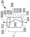
出于说明的目的,图3A示出了轴承(整体标记为31)形状,该轴承形状可通过轧制适当尺寸的复合材料1000,1001,1002零件生产而得,该复合材料最初可作为上述坯料存在。轴承31可在相对于中心轴线3000在轴向方向上延伸。即,中心轴线3000可沿轴承31的长度纵向延伸。侧壁308具有径向内端或边缘307和径向外端或边缘309。侧壁308具有内表面312和外表面314。在多个实施例中,侧壁308可包括基板1119和复合材料1000,1001,1002的至少一个低摩擦层1104,如图2A-2C所示。如上所述,低摩擦材料1104可以基本上覆盖轴承31的内表面312或外表面314中的至少一者的整体。For illustration purposes, Figure 3A shows the shape of a bearing (generally designated 31) that may be produced by rolling appropriately sized parts of
轴承31可压制成包括侧壁308,该侧壁可包括大致圆柱形主体310,该大致圆柱形主体可形成具有第一轴向端或边缘303和第二轴向端或边缘305的环形形状。如本文所用,“大致圆柱形”是指当定位在具有围绕轴线的旋转体的最佳拟合圆柱体中时,在任何位置偏离最佳拟合圆柱体不超过15%,不超过10%、不超过5%、不超过4%、不超过3%、不超过2%、或不超过1%的形状。在一个实施例中,“大致圆柱形”可指组装在内部和外部部件之间的大致圆柱形主体310,即,处于安装状态。在另一个实施例中,“大致圆柱形”可指组装之前的在内部和外部部件之间的大致圆柱形主体310,即,处于未安装状态。在特定实施例中,大致圆柱形侧壁可为圆柱形侧壁,其具有对应于围绕具有两个纵向平面端部部分的轴线的旋转的形状。在特定实施例中,圆柱形侧壁可以具有标称表面粗糙度,例如在典型机加工和制造过程中产生的标称表面粗糙度。The
仍参看图3A,如上所述,坯料可经轧制以形成轴承侧壁308,该轴承侧壁可包括可形成环形形状的大致圆柱形主体310。轧制可在轴承31、侧壁308和/或围绕中心轴线3000的大致圆柱形主体310中形成第一周向端340和第二周向端342。第一周向端340可具有第一端面。第二周向端342可具有第二端面。第一周向端340和第二周向端342的端面可适于彼此接触以形成接合面344,该接合面可形成轴向向下贯穿轴承侧壁308的轴向分切口346。轴向分切口346以任何非线性方式和/或相对于轴承31的对称轴3000倾斜(例如,斜对地)延伸也是可行的。在一些实施例中,轴向分切口346可以不联接以便于轴承31的组装。在多个特定的实施例中,轴向分切口346可以通过焊接或以其他方式联接以形成封闭轴承31。轴承31可以包括孔335。孔335可沿轴承31的轴向长度向下延伸,并且适于联接至组件的另一部件。Still referring to FIG. 3A, as described above, the billet may be rolled to form bearing
在多个实施例中,如图3A所示,轴承31可以具有从第一轴向端303到第二轴向端305的整体长度L,并且L可以为≥0.5mm、≥1mm、≥2mm、≥5mm、≥10mm、或≧50mm。长度L可为≤500mm,诸如≤250mm、≤150mm、≤100mm或≤50mm。在多个实施例中,轴承31可具有介于约3mm与50mm之间的整体长度L。应当理解,轴承31可以具有整体长度L,L可在介于上述任何最小值和最大值之间的范围内。应当进一步理解,轴承31可具有整体长度L,L可为介于上述任何最小值和最大值之间的任意值。In various embodiments, as shown in FIG. 3A, the bearing 31 may have an overall length L from the first
出于说明的目的,图3A示出了轴承(整体标记为32)形状,该轴承形状可通过轧制和凸缘加工适当尺寸的复合材料1000,1001,1002零件生产而得,该复合材料最初可作为上述坯料存在。图3B可包括图3A的所有结构和设计,为简明起见,相应的附图标记保持相同并且指代与图3A相同的结构。图3B与图3A的不同之处可在于,图3B可具有在轴向横截面中基本上为L形的环形形状。换言之,轴承32可具有沿径向和轴向方向延伸的L型轴承横截面。轴承的其他轴向横截面形状也是可能的。例如,轴承32可以具有C型轴承横截面。在多个实施例中,可通过深拉工艺获得L型轴承32,该深拉工艺包括冲压已成形轴承32。For illustration purposes, Figure 3A shows a bearing (generally designated 32) shape that can be produced by rolling and flanged appropriately sized composite 1000, 1001, 1002 parts that were initially Available as the blanks described above. Figure 3B may include all of the structures and designs of Figure 3A, for the sake of brevity, corresponding reference numerals remain the same and refer to the same structures as Figure 3A. Figure 3B may differ from Figure 3A in that Figure 3B may have an annular shape that is substantially L-shaped in axial cross-section. In other words, the bearing 32 may have an L-shaped bearing cross-section extending in radial and axial directions. Other axial cross-sectional shapes of the bearing are also possible. For example, the bearing 32 may have a C-shaped bearing cross-section. In various embodiments, the L-shaped
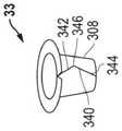
在多个实施例中,轴承侧壁308可进一步包括至少一个凸缘322。凸缘322绕中心轴线3000可大体上为环形。凸缘322可从第一轴向端303或第二轴向端305中的至少一个径向向外凸出。凸缘322可以从径向内端307向径向外端309径向向外延伸。可选地,凸缘322可以从径向外端309向径向内端307径向向内延伸(未示出)。在多个实施例中,凸缘322可在轴承32的径向外端309处形成大致平坦的最外轴向表面。在多个实施例中,凸缘322可由低摩擦层1104或低摩擦材料形成,该低摩擦层1104或低摩擦材料形成在轴承32的径向外端309处的最外轴向表面处。在多个实施例中,如从中心轴线3000径向所测量的,径向外端309可形成轴承32的外半径OR。在多个实施例中,如从中心轴线3000径向所测量的,径向内端307可形成轴承32的内半径IR。换言之,凸缘322的径向宽度WRF可为外半径OR与内半径IR的距离差。在多个实施例中,凸缘322可包括轴向开口326。轴向开口326可在凸缘322中设置孔或空间。在多个实施例中,凸缘322可包括设置分段凸缘(未示出)的多个轴向开口326。在某些实施例中,轴向开口326可与大致圆柱形主体310中的轴向分切口346邻接。In various embodiments, the bearing
在多个实施例中,至少一个凸缘322可以与轴承32的大致圆柱形主体310的轴向端303,305邻接并从其延伸。在一个实施例中,凸缘322可以位于正交于大致圆柱形主体310凸出的位置。在另一些实施例中,凸缘322可以位于非正交于大致圆柱形主体310凸出的位置。在一些实施例中,如图3B中最清楚地示出,凸缘322可以与大致圆柱形主体310(以及中心轴3000)形成夹角θ。夹角θ可以在至少0°至180°的范围内。夹角θ可以为30°或更大,诸如45°或更大、55°或更大、或85°或更大。夹角θ可以为150°或更小,诸如135°或更小、120°或更小、90°或更小、或60°或更小。在多个特定实施例中,夹角θ可以在60°至120°的范围内。In various embodiments, at least one
在多个实施例中,如图图3B所示,轴承32可以具有从中心轴线3000到径向内端306的整体内半径IR,并且IR可以为≥1mm,诸如≥5mm、≥10mm、≥15mm、≧20mm或≧50mm。内半径IR可以为≤50mm,诸如≤20mm、≤15mm、≤10mm、≤5mm或≤1mm。内半径IR可沿轴承32的圆周变化。在多个实施例中,轴承32可以具有介于约2mm至20mm之间的整体内半径IR。应当理解,轴承32可以具有整体内半径IR,IR可以在介于上述任何最小值和最大值之间的范围内。应当进一步理解,轴承32可具有整体内半径IR,IR可为介于上述任何最小值和最大值之间的任意值。In various embodiments, as shown in Figure 3B, bearing 32 may have an overall inner radius IR from
在多个实施例中,如图图3B所示,轴承32可以具有从中心轴线3000到径向外端307的整体外半径OR,并且OR可以为≧1.5mm,诸如≧5mm、≧10mm、≧20mm、≧40mm或≧70mm。外半径OR可以为≦80mm,诸如≦50mm、≦30mm、≦20mm、≦10mm或≦3mm。整体外半径OR可沿轴承32的圆周变化。在多个实施例中,轴承32可以具有介于约3mm至30mm之间的整体外半径OR。应当理解,轴承32可以具有整体外半径OR,OR可以在介于上述任何最小值和最大值之间的范围内。应当进一步理解,轴承32可以具有整体外半径OR,OR可为介于上述任何最小值和最大值之间的任意值。此外,如上所述,凸缘322的径向宽度WRF,可以为外半径OR与内半径IR之间的距离差。In various embodiments, as shown in Figure 3B, bearing 32 may have an overall outer radius OR from
在多个实施例中,如图3B所示,轴承32的凸缘322可以具有介于约0.3mm至约10mm之间的厚度TRF,诸如,介于约0.5mm至约8mm之间、介于约1mm至约5mm之间、介于约1.5mm至约4mm之间。在多个实施例中,凸缘322可以具有介于0.3mm至2mm之间的厚度TRF。应当理解的是,凸缘322可以具有厚度TRF,其可以在介于上述任何最小值和最大值之间的范围内。应当进一步理解,凸缘322可具有厚度TRF,该厚度可为介于上述任何最小值和最大值之间的任意值。还可以理解的是,凸缘322的厚度TRF可以围绕轴承32的周向变化。In various embodiments, as shown in FIG. 3B, the
出于说明的目的,图3C示出了轴承(整体标记为33)形状,该轴承形状可通过轧制和凸缘加工适当尺寸的复合材料1000,1001,1002零件生产而得,该复合材料最初可作为上述坯料存在。图3C可以包括图3A和3B的所有结构和设计,为简明起见,相应的附图标记保持相同并且指代与图3A和3B相同的结构。图3C与图3B的不同之处可在于,图3C的轴承33可包括具有锥形圆柱形部分的轴承侧壁308,该轴承侧壁可通过轧制锥形部分和凸缘加工端部来形成。For illustration purposes, Figure 3C shows the shape of a bearing (generally designated 33) that may be produced by rolling and flanged appropriately sized composite 1000, 1001, 1002 parts that were originally Available as the blanks described above. Figure 3C may include all of the structures and designs of Figures 3A and 3B, for the sake of brevity, corresponding reference numerals remain the same and refer to the same structures as Figures 3A and 3B. Figure 3C may differ from Figure 3B in that the bearing 33 of Figure 3C may include a bearing
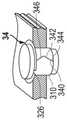
出于说明的目的,图3D示出了轴承(整体标记为34)形状,该轴承形状可通过轧制和凸缘加工适当尺寸的复合材料1000,1001,1002零件生产而得,该复合材料最初可作为上述坯料存在。图3D可以包括图3A-3C的所有结构和设计,为简明起见,相应的附图标记保持相同并且指代与图3A-3C相同的结构。图3D与图3B的不同之处可在于,图3D的轴承34示出了安装在外壳中的凸缘轴承34,并且轴销安装穿过凸缘轴承34。此外,图3D的凸缘轴承34可具有轴向开口326,该轴向开口与大致圆柱形主体310中的轴向分切口346不邻接。For illustration purposes, Figure 3D shows the shape of a bearing (generally designated 34) that can be produced by rolling and flanged appropriately sized composite 1000, 1001, 1002 parts that were initially Available as the blanks described above. Figure 3D may include all of the structures and designs of Figures 3A-3C, for the sake of brevity, corresponding reference numerals remain the same and refer to the same structures as Figures 3A-3C. FIG. 3D may differ from FIG. 3B in that the bearing 34 of FIG. 3D shows the flange bearing 34 mounted in the housing and the shaft pin is mounted through the
出于说明的目的,图3E示出了轴承(整体标记为35)形状,该轴承形状可通过轧制和凸缘加工适当尺寸的复合材料1000,1001,1002零件生产而得,该复合材料最初可作为上述坯料存在。图3E可以包括图3A-3D的所有结构和设计,为简明起见,相应的附图标记保持相同并且指代与图3A-3D相同的结构。图3E与图3B的不同之处可在于图3E示出了安装在外壳中的两侧凸缘轴承35,轴销安装穿过两侧凸缘轴承35。如图3E所示,径向凸缘322,322'可以定位在轴承35的第一轴向端303和第二轴向端305两者处。For illustration purposes, Figure 3E shows the shape of a bearing (generally designated 35) that can be produced by rolling and flanged appropriately sized composite 1000, 1001, 1002 parts that were initially Available as the blanks described above. Figure 3E may include all of the structures and designs of Figures 3A-3D, for the sake of brevity, corresponding reference numerals remain the same and refer to the same structures as Figures 3A-3D. Figure 3E may differ from Figure 3B in that Figure 3E shows a two-sided flange bearing 35 mounted in a housing through which a shaft pin is mounted. As shown in FIG. 3E ,
出于图示的目的,图3F-3G分别示出了轴承(整体标记为36)形状的放大透视图和放大侧视图,该轴承形状可通过轧制适当尺寸的复合材料1000,1001,1002零件生产而得,该复合材料最初可作为上述坯料存在。图3F-3G可以包括图3A和3B的所有结构和设计,为简明起见,相应的附图标记保持相同并且指代与图3A和3B相同的结构。For illustration purposes, Figures 3F-3G show an enlarged perspective view and an enlarged side view, respectively, of the shape of a bearing (generally designated 36) that may be obtained by rolling appropriately sized composite 1000, 1001, 1002 parts Produced, the composite material can initially exist as a blank as described above. Figures 3F-3G may include all of the structures and designs of Figures 3A and 3B, for the sake of brevity, corresponding reference numerals remain the same and refer to the same structures as Figures 3A and 3B.
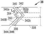
参见图3F-3G,轴承36的第一周向端340和第二周向端342可适于彼此接触以形成接合面344,该接合面可形成沿轴承侧壁308轴向延伸的轴向分切口346。第一周向端340可以形成顶点区域350。第二周向端342可以形成最低点区域352。在多个实施例中,第一周向端340可具有第一轴向腿部340a和第二轴向腿部340b。在多个实施例中,第二周向端342可具有第一轴向腿部342a和第二轴向腿部342b。在多个实施例中,第一周向端340的第一轴向腿部340a与第二周向端342的第一轴向腿部342a配对,并且第一周向端340的第二轴向腿部340b与第二周向端342的第二轴向腿部342b接触以形成V型接合面。3F-3G, the first
在多个实施例中,如图3G最清楚地示出,顶点区域350可以形成任意角α,定义为这些角≤180°,其中α至少为30°,诸如至少60°、诸如至少90°、诸如至少120°、或诸如至少150°。顶点区域350可以形成任意角α,定义为这些角≤180°,其中α不大于180°、诸如不大于120°、诸如不大于90°、诸如不大于60°、或诸如不大于45°。In various embodiments, as best shown in FIG. 3G, the
在多个实施例中,顶点区域350或最低点区域352中的至少一个可包括空隙354以防止第一周向端340的顶点区域350与第二周向端342的最低点区域352之间的接触。如图3F所示,空隙354可在最低点区域352中。如图3G所示,空隙354可在顶点区域350中。在一个实施例中,空隙354可以延伸100%的总厚度TSW,,使得空隙354可以在侧壁308中完全形成间隙356,并且向第一周向端340和第二周向端342之间的轴向分切口346增加额外空间。在一些实施例中,间隙356可以防止第一周向端和第二周向端沿它们相应的径向厚度的整体相互接触。In various embodiments, at least one of the
出于说明的目的,图3H示出了轴承(整体标记为37)形状的放大透视图,该轴承形状可通过轧制和凸缘加工适当尺寸的复合材料1000,1001,1002零件生产而得,该复合材料最初可作为上述坯料存在。图3F-3G可以包括图3A-3B的所有结构和设计,为简明起见,相应的附图标记保持相同并且指代与图3A-3B相同的结构。如图3H所示,分切口可包括在凸缘322中以形成不同的接合面344形状。许多不同的接合面344形状是可能的。For illustration purposes, Figure 3H shows an enlarged perspective view of the shape of a bearing (generally designated 37) that can be produced by rolling and flanged appropriately sized composite 1000, 1001, 1002 parts, The composite material may initially exist as a blank as described above. Figures 3F-3G may include all of the structures and designs of Figures 3A-3B, for the sake of brevity, corresponding reference numerals remain the same and refer to the same structures as Figures 3A-3B. As shown in FIG. 3H , split cuts may be included in
出于说明的目的,图3I示出了平行于中心轴线3000的平面的横截面中的轴承(整体标记为38)的近视图,该轴承可通过轧制适当尺寸的复合材料1000,1001,1002零件生产而得,该复合材料最初可作为上述坯料存在。图3I可以包括图3A-3B和3F-3G的所有结构和设计,为简明起见,相应的附图标记保持相同并且指代与图3A-3B和3F-3G相同的结构。如图3I所示,间隙356可以形成不同的接合面344形状。许多不同的接合面344形状是可能的。间隙356可在轴承38的圆周方向上具有横截面形状,包括多边形、椭圆形、圆形、半圆形,或者可为其他类型。For illustrative purposes, Figure 3I shows a close-up view of a bearing (generally designated 38) in cross-section parallel to the plane of the
如图3I所示,间隙356可在轴承38的圆周方向上具有横截面形状,包括多边形、椭圆形、圆形、半圆形,或者可为其他类型。在多个实施例中,间隙356可具有间隙长度LG,其可定义为间隙356在轴向分切口346中产生的长度的轴向投影。在多个实施例中,LG<0.5L,诸如LG<0.25L、诸如LG<0.15L、诸如LG<0.10L或诸如LG<0.05L。As shown in FIG. 3I, the
出于说明的目的,图3J示出了平行于中心轴线3000的平面的横截面中的轴承(整体标记为39)的近视图,该轴承可通过轧制适当尺寸的复合材料1000,1001,1002零件生产而得,该复合材料最初可作为上述坯料存在。图3J可包括图3A-3B和3F-3I的所有结构和设计,为简明起见,相应的附图标记保持相同并且指代与图3A-3B和3F-3I相同的结构。如图3J所示,第一周向端340的第一轴向腿部340a与第二周向端342的第一轴向腿部342a配对,并且第一周向端340的第二轴向腿部340b与第二周向端342的第二轴向腿部342b接触以形成C型接合面344以及另一个不同的接合面344形状。许多不同的接合面344形状是可能的。For illustration purposes, Figure 3J shows a close-up view of a bearing (generally designated 39) in cross-section parallel to the plane of the
出于说明的目的,图3K示出了平行于中心轴线3000的平面的横截面中的轴承(整体标记为40)的近视图,该轴承可通过轧制适当尺寸的复合材料1000,1001,1002零件生产而得,该复合材料最初可作为上述坯料存在。图3K可包括图3A-3B和3F-3J的所有结构和设计,为简明起见,相应的附图标记保持相同并且指代与图3A-3B和3F-3J相同的结构。如图3K所示,第一周向端340可具有端面341,并且第二周向端可具有端面343。第一周向端340和第二周向端342的端面341,343可适于彼此接触以形成接合面344,该接合面可形成轴向向下贯穿轴承侧壁308的轴向分切口346。如上所述,由坯料形成轴承40可包括使用印模、压力机、冲压机、锯、深拉,或者能够以不同的方式进行机加工。如图3K所示,第一周向端340或第二周向端342中的至少一个的端面341,343可由于形成过程而包括多个区域。第一周向端340或第二周向端342的端面341,343可具有包括变形区362的端面341,343。变形区362可具有厚度TD。第一周向端340或第二周向端342的端面341,343可具有包括切削区364的端面341,343。切削区364可具有厚度TC。第一周向端340或第二周向端342的端面341,343可具有包括断裂区366的端面341,343。断裂区366可具有厚度TF。For illustration purposes, FIG. 3K shows a close-up view of a bearing (generally designated 40 ) in cross-section in a plane parallel to the
在一些实施例中,变形区362的厚度TD可为侧壁308的总厚度TSW,的至少5%,诸如侧壁308的总厚度TSW,的至少1%、诸如侧壁308的总厚度TSW,的至少5%、诸如侧壁308的总厚度TSW,的至少10%、或诸如侧壁308的总厚度TSW,的至少20%。In some embodiments, the thickness TD of the
在一些实施例中,切削区364的厚度TC可为侧壁308的总厚度TSW,的至少5%,诸如侧壁308的总厚度TSW,的至少10%、诸如侧壁308的总厚度TSW,的至少15%、诸如侧壁308的总厚度TSW,的至少20%、诸如侧壁308的总厚度TSW,的至少25%、诸如侧壁308的总厚度TSW,的至少30%、或诸如侧壁308的总厚度TSW,的至少40%。In some embodiments, the thickness TC of the cutting
在一些实施例中,断裂区366的厚度TF可为侧壁308的总厚度TSW,的至少5%,诸如侧壁308的总厚度TSW,的至少10%、诸如侧壁308的总厚度TSW,的至少20%、诸如侧壁308的总厚度TSW,的至少30%、诸如侧壁308的总厚度TSW,的至少40%、诸如侧壁308的总厚度TSW,的至少50%、或诸如侧壁308的总厚度TSW,的至少60%。In some embodiments, the thickness TF of the
如上所述,轴承40可通过轧制适当尺寸的复合材料1000,1001,1002零件生产而得,该复合材料最初可作为上述坯料存在。轴承40可以具有形成内表面312和外表面314的侧壁308,其中低摩擦层1104或低摩擦材料1104基本上覆盖内表面312或外表面314中的至少一者的整体。此外,第一周向端340的端面341可不含低摩擦层1104或低摩擦材料1104。此外,第二周向端342的端面343可不含低摩擦层1104或低摩擦材料1104。此外,第一周向端340和第二周向端342的端面341,343可不含低摩擦层1104或低摩擦材料1104。此外,低摩擦层1104或低摩擦材料1104可以延伸直至第一周向端和第二周向端340,342的端面341,343,使得在外表面314或内表面312中的至少一个和第一或第二周向端340,342中的至少一个之间的交点处没有可见的裸露基板1119。在又一个实施例中,重新参见图3A,轴承31可具有侧壁308,侧壁308具有第一轴向边缘303和第二轴向边缘305,其中第一轴向边缘303或第二轴向边缘305中的至少一个不含低摩擦层1104或低摩擦材料1104,通过冲压或切割产生与上图3K中关于第一周向端340或第二周向端342所示的类似结果。As described above, the bearing 40 may be produced by rolling appropriately sized parts of
出于图示的目的,图3L-3O示出了平行于中心轴线3000的平面的横截面中的轴承(整体标记分别为41-44)的放大侧视图,该轴承可通过轧制适当尺寸的复合材料1000,1001,1002零件生产而得,该复合材料最初可作为上述坯料存在。如图3L和3O所示,第一周向端340可在第一轴向腿部340a或第二轴向腿部340b处与大致圆柱形主体310的第一轴向端303形成角度β1。角度β1可小于90°。角度β1可以为5°或更大,诸如15°或更大、25°或更大、或45°或更大。角度β1可以为90°或更小,诸如85°或更小、75°或更小、60°或更小、或45°或更小。在多个特定实施例中,角度β1可以在15°至60°的范围内。第二周向端342可在第一轴向腿部342a或第二轴向腿部342b处与大致圆柱形主体310的第一轴向端303形成角度β2。角度β2可以为5°或更大,诸如15°或更大、25°或更大、或45°或更大。角度β2可以为90°或更小,诸如85°或更小、75°或更小、60°或更小、或45°或更小。在多个特定实施例中,角度β2可以在15°至60°的范围内。在多个实施例中,β1可以等于或基本等于β2,如图3L中最清楚地示出。在多个实施例中,β1可以基本上不同于β2,如图3O中最清楚地示出。β1必须大于或等于β2。在多个实施例中,第一周向端340可以具有曲率半径R1,其中大致圆柱形主体310的第一轴向端303在沿第一轴向腿部340a、第二轴向腿部340b或顶点区域350的点处。在多个实施例中,第二周向端342可以具有曲率半径R2,其中大致圆柱形主体310的第一轴向端303或第二轴向端305在沿第一轴向腿部340a、第二轴向腿部340b或最低点区域352的点处。在一些实施例中,第一周向端340的顶点区域350可具有曲率半径R1,并且第二周向端342的最低点区域352可具有曲率半径R2,其中R R1>R2,诸如0.75R1>R2、诸如0.5R1>R2、诸如0.25R1>R2、或诸如0.1R1>R2。在一个实施例中,如图3L中最清楚地示出,第一周向端340的第一轴向腿部340a和第二周向端342的第一轴向腿部320a可沿其长度具有相同的曲率半径,并且第一周向端340的第二轴向腿部340b和第二周向端342的第二轴向腿部340b可沿其长度具有相同的曲率半径。在一个实施例中,如图3O中最清楚地示出,第一周向端340的第一轴向腿部340a和第二周向端342的第一轴向腿部320a可沿其长度具有不同的曲率半径,并且第一周向端340的第二轴向腿部340b和第二周向端342的第二轴向腿部340b可沿其长度具有不同的曲率半径。在沿第一周向端340的点处的曲率半径R1可以是正的或负的。在沿第二周向端342的点处的曲率半径R2可以是正的或负的。例如,图3M示出在第一周向端340的沿曲率半径R1的点和在第二周向端342的沿曲率半径R2的点处为负值的曲率半径。C1和C2不能垂直于第一轴向端303或第二轴向端305终止。或者,图3N示出在第一周向端340的沿曲率半径R1的点和在第二周向端342的沿曲率半径R2的点处为负值的曲率半径。For illustration purposes, FIGS. 3L-3O show enlarged side views of the bearing (generally labeled 41-44, respectively) in cross-section in a plane parallel to the
在多个实施例中,如上所述,本文公开的任何示例性轴承可以包括在组件中。组件可进一步包括内部部件,诸如轴。组件可进一步包括外部部件,诸如外壳。组件可进一步包括设置在该内部部件与外部部件之间的轴承。轴承可以包括轴承侧壁,轴承侧壁包括第一周向端和第二周向端,第一周向端包括顶点区域,第二周向端包括最低点区域。第一周向端和第二周向端可以适于彼此接触以形成接合面,其中顶点区域或最低点区域中的至少一者包括空隙以防止第一周向端的顶点区域与第二周向端的最低点区域之间的接触。轴承侧壁可包括基板和低摩擦材料,其中第一周向端或第二周向端的端面中的至少一个可不含低摩擦材料。In various embodiments, any of the exemplary bearings disclosed herein may be included in an assembly, as described above. The assembly may further include internal components, such as shafts. The assembly may further include external components, such as a housing. The assembly may further include a bearing disposed between the inner member and the outer member. The bearing may include a bearing side wall including a first circumferential end including a apex region and a second circumferential end including a nadir region. The first circumferential end and the second circumferential end may be adapted to contact each other to form a joint, wherein at least one of the apex region or the nadir region includes a gap to prevent the apex region of the first circumferential end and the nadir of the second circumferential end contact between regions. The bearing sidewall may include a base plate and a low friction material, wherein at least one of the end faces of the first circumferential end or the second circumferential end may be free of the low friction material.
图4和5示出了呈示例性铰链400形式的组件2000,诸如汽车门铰链、发动机罩铰链、发动机舱铰链等。图5是图4中的组件200的放大横截面视图。铰链400可以包括内部部件28(诸如内部铰链部分402)和外部铰链部分404。铰链部分402和404可以通过外部部件(诸如铆钉406和408)以及轴承410和412进行连接。轴承410和412可以是如前所述的轴承,并在本文中标记为31-40。图5示出了铰链400的横截面,更详细地示出了铆钉408和轴承412。4 and 5 illustrate an
图6示出了另一个示例性铰链600形式的组件2001。铰链600可以包括由销606和轴承608连接的第一铰链部分602和第二铰链部分604。轴承608可以是如前所述的轴承,并在本文中标记为31-40。FIG. 6 shows an
在一个示例性实施例中,图7描绘了呈另一铰链组件700的实施例形式的组件2002的非限制性实例,该另一铰链组件包括已拆卸的汽车门铰链的部件,该汽车门铰链包括轴承704。图7为型材铰链的实例。轴承704可插入铰链门零件706中。轴承704可以是如前所述的轴承,并在本文中标记为31-40。铆钉708将铰链门零件706与铰链大致圆柱形主体零件710桥接。铆钉708可通过定位螺钉712与铰链大致圆柱形主体零件710相拧紧,并且通过垫圈702与铰链门零件706固定到位。In one exemplary embodiment, FIG. 7 depicts a non-limiting example of an
图8示出了呈示例性碗组组件800形式的组件2003,该碗组组件用于两轮车辆,诸如自行车或摩托车。转向管802可以插入并穿过头管804。轴承806和808可以放置在转向管802和头管804之间,以保持对准并防止转向管802和头管804接触。轴承806和808可以是如前所述的轴承,并在本文中标记为31-40。此外,密封件810和812可以防止轴承的滑动表面被灰尘和其他颗粒物质污染。FIG. 8 shows an
上面提到的这些组件都是示例性的,并不意味着限制轴承在其他潜在组件中的使用。例如,轴承可在用于动力组件应用(诸如皮带张力器)或其他空间有限的组件应用的组件中使用。The assemblies mentioned above are exemplary and are not meant to limit the use of the bearing in other potential assemblies. For example, bearings may be used in assemblies for power assembly applications such as belt tensioners or other space-constrained assembly applications.
形成轴承的方法可包括提供坯料。轴承可以由包括材料条带的坯料形成,该材料条带包括层压材料,层压材料包括基板和覆盖基板的低摩擦层。材料条带可以成形为具有第一端和第二端,其中成形包括使第一端成形以形成顶点区域和使第二端成形以形成最低点区域,其中顶点区域或顶点区域中的至少一者包括一个空隙。该方法还可以包括对条带进行辊轧成形以形成环形轴承,其中第一端和第二端分别形成互补的第一周向端和第二周向端。The method of forming the bearing may include providing a blank. The bearing may be formed from a blank comprising a strip of material comprising a laminate comprising a substrate and a low friction layer overlying the substrate. The strip of material can be shaped to have a first end and a second end, wherein the shaping includes shaping the first end to form an apex region and shaping the second end to form a nadir region, wherein at least one of the apex region or the apex region Include a gap. The method may also include roll forming the strip to form the annular bearing, wherein the first and second ends form complementary first and second circumferential ends, respectively.
此类实施例的应用包括,例如,用于铰链和其他车辆部件的组件。进一步地,使用轴承或组件可在若干应用中提供更多益处,该应用诸如但不限于车辆尾门、门框、座椅组件、动力系统应用(如安全带张紧器)或其他类型的应用。根据本文实施例,剖分轴承可以通过提供变形以使得第二周向端轴向受力远离第一周向端而在高压入配合条件下更好地保持“圆柱度”,从而相较于本领域中已知的现有轴承保持更一致的轴承半径。因此,根据本文实施例的剖分轴承允许轴承保持压入配合所需的环向应力并保持轴承的轴向边缘之间相对于彼此的对准。换言之,本文提供的实施例可以减少或消除由热膨胀和/或高负载条件引起的径向弯曲和/或“高点”,这通常由本领域已知的现有轴承在高压条件下表现出。因此,根据本文实施例的剖分轴承可缩小扭矩范围、提高同心度并减少轴承表面的磨损,从而增加寿命并提高组件、轴承及其其他部件的有效性和性能。Applications for such embodiments include, for example, assemblies for hinges and other vehicle components. Further, the use of bearings or assemblies may provide additional benefits in several applications such as, but not limited to, vehicle tailgates, door frames, seat assemblies, powertrain applications such as seat belt tensioners, or other types of applications. According to embodiments herein, the split bearing can better maintain "cylindricity" under high pressure fit conditions by providing deformation such that the second circumferential end is axially forced away from the first circumferential end, thereby providing a higher degree of "cylindricity" than in the art Known existing bearings maintain a more consistent bearing radius. Accordingly, a split bearing according to embodiments herein allows the bearing to maintain the hoop stress required for a press fit and maintain alignment between the axial edges of the bearing relative to each other. In other words, the embodiments provided herein may reduce or eliminate radial buckling and/or "high spots" caused by thermal expansion and/or high load conditions commonly exhibited by existing bearings known in the art under high pressure conditions. Accordingly, split bearings according to embodiments herein can reduce torque range, improve concentricity, and reduce wear on bearing surfaces, thereby increasing life and improving the effectiveness and performance of assemblies, bearings, and other components.
许多不同的方面和实施例都是可能的。以下描述了那些方面和实施例中的一些。在阅读本说明书之后,本领域的技术人员会理解,那些方面和实施例仅是说明性的,并不限制本发明的范围。实施例可以根据下面列出的任何一个或多个实施例。Many different aspects and embodiments are possible. Some of those aspects and embodiments are described below. After reading this specification, those skilled in the art will understand that those aspects and examples are illustrative only and do not limit the scope of the invention. Embodiments may be in accordance with any one or more of the embodiments listed below.
实施例1.一种轴承,所述轴承包括:轴承侧壁,所述轴承侧壁包括第一周向端和第二周向端,所述第一周向端包括顶点区域,所述第二周向端包括最低点区域,其中所述第一周向端和所述第二周向端适于彼此接触以形成接合面,其中所述顶点区域或所述最低点区域中的至少一者包括空隙以防止所述第一周向端的所述顶点区域与所述第二周向端的所述最低点区域之间的接触,其中所述轴承侧壁包括基板和低摩擦材料,并且其中所述第一周向端或所述第二周向端中的至少一者包括不含低摩擦材料的端面。Embodiment 1. A bearing comprising: a bearing side wall comprising a first circumferential end and a second circumferential end, the first circumferential end comprising an apex region, the second circumferential end comprising A nadir region, wherein the first circumferential end and the second circumferential end are adapted to contact each other to form a joint, wherein at least one of the apex region or the nadir region includes a void to prevent the first circumferential end Contact between the apex region of the circumferential end and the nadir region of the second circumferential end, wherein the bearing sidewall includes a base plate and a low friction material, and wherein the first circumferential end or the At least one of the second circumferential ends includes an end face free of low friction material.
实施例2.一种组件,所述组件包括内部部件;外部部件;和设置在所述内部部件和所述外部部件之间的轴承,其中所述轴承包括轴承侧壁,所述轴承侧壁包括第一周向端和第二周向端,所述第一周向端包括顶点区域,所述第二周向端包括最低点区域,其中所述第一周向端和所述第二周向端适于彼此接触以形成接合面,其中所述顶点区域或所述最低点区域中的至少一者包括空隙以防止所述第一周向端的所述顶点区域与所述第二周向端的所述最低点区域之间的接触,其中所述轴承侧壁包括基板和低摩擦材料,并且其中所述第一周向端或所述第二周向端中的至少一者包括不含低摩擦材料的端面。Embodiment 2. An assembly comprising an inner member; an outer member; and a bearing disposed between the inner member and the outer member, wherein the bearing includes a bearing side wall comprising A first circumferential end and a second circumferential end, the first circumferential end including an apex region, the second circumferential end including a nadir region, wherein the first circumferential end and the second circumferential end are adapted to contact each other to forming a joint, wherein at least one of the apex region or the nadir region includes a void to prevent space between the apex region of the first circumferential end and the nadir region of the second circumferential end contact, wherein the bearing sidewall includes a base plate and a low friction material, and wherein at least one of the first circumferential end or the second circumferential end includes an end face that is free of low friction material.
实施例3.一种方法,所述方法包括对包含基板和低摩擦材料的材料条带进行成型,所述条带具有第一端和第二端,其中成型包括将所述第一端成型以形成顶点区域和将所述第二端成型以形成最低点区域,其中所述顶点区域或所述最低点区域中的至少一者包括空隙;以及对条带进行辊轧成形以形成环形轴承,其中第一端和第二端分别形成互补的第一周向端和第二周向端。Embodiment 3. A method comprising forming a strip of material comprising a substrate and a low friction material, the strip having a first end and a second end, wherein forming comprises forming the first end to forming an apex region and forming the second end to form a nadir region, wherein at least one of the apex region or the nadir region includes a void; and roll forming a strip to form an annular bearing, wherein The first and second ends form complementary first and second circumferential ends, respectively.
实施例4.根据前述实施例中任一项所述的轴承、组件或方法,其中所述轴承侧壁包括第一轴向端和第二轴向端,其中所述第一轴向端或所述第二轴向端中的至少一个不含低摩擦材料。Embodiment 4. The bearing, assembly, or method of any preceding embodiment, wherein the bearing sidewall includes a first axial end and a second axial end, wherein the first axial end or the At least one of the second axial ends is free of low friction material.
实施例5.根据前述实施例中任一项所述的轴承、组件或方法,其中所述轴承侧壁包括外表面和内表面,其中所述低摩擦材料基本上覆盖所述外表面或所述内表面中的至少一者的整体。
实施例6.根据实施例5所述的轴承、组件或方法,其中低摩擦材料延伸直至所述第一周向端和所述第二周向端中的至少一者的端面。Embodiment 6. The bearing, assembly, or method of
实施例7.根据前述实施例中任一项所述的轴承、组件或方法,其中所述第一周向端或所述第二周向端中的至少一者的端面包括包含变形区、切削区和断裂区。Embodiment 7. The bearing, assembly, or method of any one of the preceding Embodiments, wherein the end face of at least one of the first circumferential end or the second circumferential end includes a deformation zone, a cutting zone, and fracture zone.
实施例8.根据前述实施例中任一项所述的轴承、组件或方法,其中第一周向端具有径向厚度并且第二周向端具有径向厚度,并且其中第一周向端和第二周向端沿它们相应的径向厚度的整体彼此接触。Embodiment 8. The bearing, assembly, or method of any preceding Embodiment, wherein the first circumferential end has a radial thickness and the second circumferential end has a radial thickness, and wherein the first circumferential end and the second circumferential end have a radial thickness. The circumferential ends contact each other along the entirety of their respective radial thicknesses.
实施例9.根据前述实施例中任一项所述的轴承、组件或方法,其中所述空隙在所述第一周向端和所述第二周向端之间形成间隙。Embodiment 9. The bearing, assembly, or method of any of the preceding Embodiments, wherein the void forms a gap between the first circumferential end and the second circumferential end.
实施例10.根据实施例9所述的轴承、组件或方法,其中所述接合面具有接合面长度L,并且所述间隙具有间隙长度Lg,并且其中G,并且其中LG<0.25L,诸如LG<0.20L、诸如LG<0.15L、诸如LG<0.10L或诸如LG<0.05L。
实施例11.根据前述实施例中任一项所述的轴承、组件或方法,其中所述第一周向端的所述顶点区域具有曲率半径R1,并且所述第二周向端的所述最低点区域具有曲率半径R2,并且其中R1>R2。Embodiment 11. The bearing, assembly or method of any one of the preceding Embodiments, wherein the apex region of the first circumferential end has a radius of curvature R1 , and the lowermost end of the second circumferential end The point region has a radius of curvature R2 , and where R1 >R2 .
实施例12.根据前述实施例中任一项所述的轴承、组件或方法,其中所述第一周向端包括第一轴向腿部和第二轴向腿部,其中所述第二周向端包括第一轴向腿部和第二轴向腿部,使得所述第一周向端与所述第二周向端接触以形成V型接合面。
实施例13.根据前述实施例中任一项所述的轴承、组件或方法,其中所述第一周向端包括第一轴向端和第二轴向端,其中所述第二周向端包括第一轴向端和第二轴向端,使得所述第一周向端与所述第二周向端接触以形成C型接合面。Embodiment 13. The bearing, assembly, or method of any of the preceding Embodiments, wherein the first circumferential end includes a first axial end and a second axial end, wherein the second circumferential end includes a first circumferential end. An axial end and a second axial end such that the first circumferential end contacts the second circumferential end to form a C-shaped engagement surface.
实施例14.根据实施例13所述的轴承、组件或方法,其中所述第一周向端的所述第一轴向端和所述第二周向端的所述第一轴向端沿其长度具有相同的曲率半径,并且其中所述第一周向端的所述第二轴向端周向端和第二周向端的第二轴向端沿其长度具有相同的曲率半径。
实施例15.根据前述实施例中任一项所述的轴承、组件或方法,其中所述顶点区域形成任意角α,定义为这些角≤180°,其中α为至少30°,诸如至少60°、诸如至少90°、诸如至少120°、或诸如至少150°。Embodiment 15. The bearing, assembly or method of any one of the preceding embodiments, wherein the apex region forms any angle a, defined as those angles ≤ 180°, wherein a is at least 30°, such as at least 60° , such as at least 90°, such as at least 120°, or such as at least 150°.
实施例16.根据前述实施例中任一项所述的轴承、组件或方法,其中所述顶点区域形成任意角α,定义为这些角≤180°,其中α不大于180°,诸如不大于120°、诸如不大于90°、诸如不大于60°、或诸如不大于45°。
实施例17.根据前述实施例中任一项所述的轴承、组件或方法,其中所述基板包含钢。Embodiment 17. The bearing, assembly, or method of any of the preceding Embodiments, wherein the substrate comprises steel.
实施例18.根据前述实施例中任一项所述的轴承、组件或方法,其中所述低摩擦材料包括聚酮、聚芳酰胺、热塑性聚酰亚胺、聚醚酰亚胺、聚苯硫醚、聚醚砜、聚砜、聚苯砜、聚酰胺酰亚胺、超高分子量聚乙烯、含氟聚合物、聚酰胺、聚苯并咪唑或其任何组合。Embodiment 18. The bearing, assembly, or method of any preceding embodiment, wherein the low friction material comprises polyketone, polyaramid, thermoplastic polyimide, polyetherimide, polyphenylene sulfide ether, polyethersulfone, polysulfone, polyphenylsulfone, polyamideimide, ultra-high molecular weight polyethylene, fluoropolymer, polyamide, polybenzimidazole, or any combination thereof.
实施例19.根据前述实施例中任一项所述的轴承、组件或方法,其中所述轴承侧壁包括大致圆柱形主体和径向凸缘。Embodiment 19. The bearing, assembly, or method of any of the preceding Embodiments, wherein the bearing sidewall includes a generally cylindrical body and a radial flange.
实施例20.根据前述实施例中任一项所述的轴承、组件或方法,其中所述径向凸缘包括在所述第一周向端和所述第二周向端之间的接合面处的开口。Embodiment 20. The bearing, assembly, or method of any of the preceding Embodiments, wherein the radial flange includes a rib at the interface between the first and second circumferential ends. Open your mouth.
需注意,并非需要上述所有特征,可能不需要特定特征的一部分,并且除了所描述的特征之外,还可提供一个或多个特征。此外,描述特征的顺序不一定是安装特征的顺序。It is to be noted that not all of the features described above are required, that some of the particular features may not be required and that one or more features may be provided in addition to those described. Furthermore, the order in which the features are described is not necessarily the order in which the features are installed.
为清楚起见,本文中在单独的实施例的上下文中描述的某些特征,也可在单个实施例中以组合的方式来提供。相反地,为简明起见,在单个实施例的上下文中描述的各种特征也可单独地提供或以任何子组合的方式来提供。For clarity, certain features that are described herein in the context of separate embodiments can also be provided in combination in a single embodiment. Conversely, various features that are, for brevity, described in the context of a single embodiment, may also be provided separately or in any subcombination.
上文已经参考具体实施例描述了益处、其他优点及问题的解决方案。然而,益处、优点、问题的解决方案以及可使任何益处、优点或解决方案出现或变得更加显著的任何特征都不应理解为是任何或所有权利要求的关键、所需或必要的特征。Benefits, other advantages, and solutions to problems have been described above with reference to specific embodiments. However, benefits, advantages, solutions to problems, and any feature that would make any benefit, advantage, or solution appear or be more pronounced, should not be construed as a key, required, or essential feature of any or all of the claims.
本文所述的实施例的说明书和图示旨在提供对各种实施例的结构的一般理解。说明书和图示并不旨在用作对使用了本文所述的结构或方法的装置和系统的所有元件和特征的详尽和全面的描述。单独的实施例也可在单个实施例中以组合的方式来提供,并且相反地,为简明起见而在单个实施例的上下文中描述的各种特征也可单独地提供或以任何子组合的方式来提供。进一步地,对以范围表示的值的引用包括该范围内的每个值和所有各值。只有在阅读本说明书之后,许多其他实施例对于技术人员才是显而易见的。通过本公开内容可以利用和得到其他实施例,使得可在不偏离本公开的范围的情况下进行结构替换、逻辑替换或任何改变。因此,本公开应被视为说明性的而非限制性的。The descriptions and illustrations of the embodiments described herein are intended to provide a general understanding of the structure of the various embodiments. The specification and illustrations are not intended to serve as an exhaustive and comprehensive description of all elements and features of devices and systems that employ the structures or methods described herein. Separate embodiments may also be provided in combination in a single embodiment, and conversely various features that are, for brevity, described in the context of a single embodiment may also be provided separately or in any subcombination to provide. Further, references to values expressed in ranges include each and every value within that range. Many other embodiments will be apparent to the skilled person only after reading this specification. Other embodiments may be utilized and derived from the present disclosure, such that structural substitutions, logical substitutions, or any changes may be made without departing from the scope of the present disclosure. Accordingly, the present disclosure should be regarded as illustrative rather than restrictive.
Claims (15)
Translated fromChineseApplications Claiming Priority (3)
| Application Number | Priority Date | Filing Date | Title |
|---|---|---|---|
| US201962932698P | 2019-11-08 | 2019-11-08 | |
| US62/932,698 | 2019-11-08 | ||
| PCT/US2020/059400WO2021092372A1 (en) | 2019-11-08 | 2020-11-06 | Split bearing, assembly, and method of making and using the same |
Publications (2)
| Publication Number | Publication Date |
|---|---|
| CN114641621Atrue CN114641621A (en) | 2022-06-17 |
| CN114641621B CN114641621B (en) | 2023-12-12 |
Family
ID=75846585
Family Applications (1)
| Application Number | Title | Priority Date | Filing Date |
|---|---|---|---|
| CN202080077195.3AActiveCN114641621B (en) | 2019-11-08 | 2020-11-06 | Dissection of bearings, components and methods of making and using them |
Country Status (8)
| Country | Link |
|---|---|
| US (1) | US11286986B2 (en) |
| EP (1) | EP4055291A4 (en) |
| JP (2) | JP2022552710A (en) |
| KR (2) | KR20220093201A (en) |
| CN (1) | CN114641621B (en) |
| CA (1) | CA3160643A1 (en) |
| MX (1) | MX2022005331A (en) |
| WO (1) | WO2021092372A1 (en) |
Cited By (2)
| Publication number | Priority date | Publication date | Assignee | Title |
|---|---|---|---|---|
| TWI826305B (en)* | 2023-04-18 | 2023-12-11 | 金盛元興業股份有限公司 | Bearing for a bicycle |
| TWI856614B (en)* | 2023-04-18 | 2024-09-21 | 金盛元興業股份有限公司 | Bearing for a bicycle |
Families Citing this family (6)
| Publication number | Priority date | Publication date | Assignee | Title |
|---|---|---|---|---|
| JP6799694B2 (en)* | 2017-03-09 | 2020-12-16 | オエティカ シュヴァイツ アーゲー | How to make a welding ring |
| DE102020208272A1 (en)* | 2020-07-02 | 2022-01-05 | Aktiebolaget Skf | Sheet metal track with recesses |
| DE102020208270A1 (en) | 2020-07-02 | 2022-01-05 | Aktiebolaget Skf | Raceway element with contoured abutting edge |
| DE102020208269A1 (en) | 2020-07-02 | 2022-01-05 | Aktiebolaget Skf | Track element and process for its manufacture |
| JP7212111B2 (en)* | 2020-07-24 | 2023-01-24 | ティーイー コネクティビティ ジャーマニー ゲゼルシャフト ミット ベシュレンクテル ハフツンク | Electrical ferrules, electrical connection devices, and electrical connectors |
| JP7521420B2 (en)* | 2020-12-24 | 2024-07-24 | 株式会社デンソー | Damper, electronic control device, and assembly method |
Citations (22)
| Publication number | Priority date | Publication date | Assignee | Title |
|---|---|---|---|---|
| US5971983A (en)* | 1997-05-09 | 1999-10-26 | The Regents Of The University Of California | Tissue ablation device and method of use |
| GB0127687D0 (en)* | 2000-11-20 | 2002-01-09 | Daido Metal Co Ltd | Shaft bearing member |
| US6485186B2 (en)* | 2000-12-01 | 2002-11-26 | The Torrington Company | Split bearing ring and method for manufacturing same |
| US20060257058A1 (en)* | 2005-05-12 | 2006-11-16 | Stabitec Stanz-Biegetechnik Gmbh | Bearing, particularly rubber bearing |
| US7270484B2 (en)* | 2004-05-26 | 2007-09-18 | Koyo Seiko Co., Ltd. | Split outer race, split rolling bearing using same, and manufacturing method for split outer race |
| US20080292235A1 (en)* | 2007-05-25 | 2008-11-27 | Kabushiki Kaisha Toshiba | Sliding material, method of manufacturing same and bearing assembly |
| AT505550A4 (en)* | 2007-10-31 | 2009-02-15 | Hoerbiger Kompressortech Hold | MULTIPLE PACKING RING |
| DE102008047453A1 (en)* | 2008-09-17 | 2010-04-15 | Ab Skf | Thrust washer for bearing bush, comprises component which has material, where another component is arranged in areas radially outside former component, and latter component has another material |
| US7866891B2 (en)* | 2007-03-02 | 2011-01-11 | Jtekt Corporation | Rolling bearing apparatus |
| GB201110083D0 (en)* | 2010-06-16 | 2011-07-27 | Element Six Production Pty Ltd | Superhard cutter |
| EP2495464A1 (en)* | 2011-03-03 | 2012-09-05 | TPR Co., Ltd. | Support member |
| JP2013002517A (en)* | 2011-06-15 | 2013-01-07 | Ntn Corp | Multilayer bearing manufacturing method and multilayer bearing |
| WO2014021253A1 (en)* | 2012-08-01 | 2014-02-06 | 大豊工業株式会社 | Sliding bearing and manufacturing method thereof |
| US8894292B2 (en)* | 2008-05-19 | 2014-11-25 | Jtekt Corporation | Split outer ring, split rolling bearing using the same ring and construction and method of mounting the same rolling bearing |
| US20150260222A1 (en)* | 2014-03-14 | 2015-09-17 | Daido Metal Company Ltd. | Sliding bearing |
| WO2016097284A1 (en)* | 2014-12-19 | 2016-06-23 | Saint-Gobain Performance Plastics Pampus Gmbh | Sliding component and method of forming the same |
| US20160230807A1 (en)* | 2015-02-09 | 2016-08-11 | Daido Metal Company Ltd. | Main bearing for crankshaft of internal combustion engine |
| US20160245102A1 (en)* | 2015-02-20 | 2016-08-25 | Rolls-Royce North American Technologies, Inc. | Segmented turbine shroud with sealing features |
| US20160290390A1 (en)* | 2015-03-31 | 2016-10-06 | Saint-Gobain Performance Plastics Pampus Gmbh | Bearing with flange segments |
| WO2017017254A1 (en)* | 2015-07-29 | 2017-02-02 | Universitaet Stuttgart | Method for friction stir welding and friction-stir-welded workpiece |
| EP3453904A1 (en)* | 2017-09-08 | 2019-03-13 | China Communications Construction Company Limited | Bearing structural member, support, joint assembly and tube section assembly |
| US20190093401A1 (en)* | 2017-09-26 | 2019-03-28 | Saint-Gobain Performance Plastics Pampus Gmbh | Bearing, hinge assemblies, and method of making and using the same |
Family Cites Families (37)
| Publication number | Priority date | Publication date | Assignee | Title |
|---|---|---|---|---|
| US1271077A (en)* | 1917-09-01 | 1918-07-02 | Paul Frances Probasco | Piston-ring. |
| US1715268A (en)* | 1927-04-01 | 1929-05-28 | Gen Motors Corp | Method of making bearings |
| US2177584A (en)* | 1937-03-27 | 1939-10-24 | Salansky Franz | Method of making bushings |
| US2528987A (en)* | 1940-05-11 | 1950-11-07 | Albett Charles Antony | Ball and roller bearing |
| US2762117A (en) | 1953-07-13 | 1956-09-11 | Gen Motors Corp | Method of forming an interlocking bushing |
| FR1116088A (en)* | 1954-11-09 | 1956-05-03 | Hohenzollern Huettenverwalt | Composite pad |
| US3507022A (en) | 1968-02-07 | 1970-04-21 | Textron Inc | Plastic impregnated fabric journal bearing |
| US3710674A (en)* | 1970-12-18 | 1973-01-16 | Meteor Res Ltd | Expandable fastener |
| AT335234B (en)* | 1975-09-24 | 1977-02-25 | Miba Gleitlager Ag | SLIDING BEARING AND METHOD OF ITS MANUFACTURING |
| JPS5523215Y2 (en)* | 1976-07-06 | 1980-06-03 | ||
| JPS5337262A (en)* | 1976-09-17 | 1978-04-06 | Ntn Toyo Bearing Co Ltd | Manufacturing method of split bearing ring |
| JPS6133719A (en)* | 1984-07-26 | 1986-02-17 | Daido Metal Kogyo Kk | Method and device for producing bush with flange |
| JPS63195415A (en)* | 1987-02-05 | 1988-08-12 | Daido Metal Kogyo Kk | Male/female mating type bush bearing with at least two joints |
| JPS63303218A (en) | 1987-06-02 | 1988-12-09 | Daido Metal Kogyo Kk | Joint type roll bush bearing having same-shaped joint part at both ends of joint |
| DE4311634A1 (en)* | 1992-04-09 | 1993-10-14 | Rabe Thore | Inexpensive tubular low-friction bearing prodn. - comprises injection-, transfer-, etc. moulding thin inner low-friction layer on core, using fibre-free material and abrasive filler(s) |
| US5251986A (en)* | 1992-08-10 | 1993-10-12 | Grumman Aerospace Corporation | Bushing assembly |
| JP3056998B2 (en) | 1996-01-31 | 2000-06-26 | 大同メタル工業株式会社 | Half plain bearing |
| US5803614A (en)* | 1996-07-15 | 1998-09-08 | Daido Metal Company, Ltd. | Bearing structure of sliding bearing |
| GB9713079D0 (en)* | 1997-06-21 | 1997-08-27 | T & N Technology Ltd | Manufacture of plain bearings |
| DE19907571A1 (en) | 1999-02-23 | 2000-09-14 | Ks Gleitlager Gmbh | Rolled plain bearing bush |
| JP2002195261A (en)* | 2000-12-26 | 2002-07-10 | Hitachi Constr Mach Co Ltd | Bush and manufacturing method of bush |
| JP2005180459A (en)* | 2003-11-27 | 2005-07-07 | Nsk Ltd | Roller bearing, race board manufacturing method and holding body manufacturing method |
| US8132550B2 (en) | 2006-09-04 | 2012-03-13 | Ntn Corporation | Roller bearing, camshaft support structure, and internal combustion engine |
| JP5387022B2 (en)* | 2008-03-24 | 2014-01-15 | 新日鐵住金株式会社 | Punching method using chamfering die and hole punching device for metal plate stretch flange processing |
| CN102149932B (en)* | 2008-09-04 | 2016-11-16 | 光洋轴承北美有限责任公司 | The method manufacturing two-piece bearing ring |
| WO2010103899A1 (en) | 2009-03-11 | 2010-09-16 | Ntn株式会社 | Half-divided outer race, roller bearing and rotary shaft bearing arrangement |
| US8944690B2 (en) | 2009-08-28 | 2015-02-03 | Saint-Gobain Performance Plastics Pampus Gmbh | Corrosion resistant bushing |
| TWI487850B (en)* | 2009-09-25 | 2015-06-11 | Saint Gobain Performance Plast | System, method and apparatus for tolerance ring control of slip interface sliding forces |
| US8500335B2 (en) | 2010-07-30 | 2013-08-06 | Daido Metal Company Ltd. | Manufacturing method of half bearing and half plain bearing |
| JP5911026B2 (en)* | 2010-09-28 | 2016-04-27 | サン−ゴバン パフォーマンス プラスティックス コーポレイション | Cast fluoropolymer film for bushing |
| JP5649740B2 (en)* | 2010-11-19 | 2015-01-07 | サン−ゴバン パフォーマンス プラスティックス コーポレイション | Bushing, composite, and method of forming a bushing |
| KR101514228B1 (en)* | 2011-03-22 | 2015-04-22 | 생-고뱅 퍼포먼스 플라스틱스 코포레이션 | Bushing with transfigurable electrical conduction state |
| CN104395070A (en)* | 2012-07-13 | 2015-03-04 | 圣戈班性能塑料帕姆普斯有限公司 | Corrosion reducing flexible plain bearing material and method of forming the same |
| DE102014203913A1 (en)* | 2014-03-04 | 2015-09-10 | Federal-Mogul Wiesbaden Gmbh | Rifle |
| MX390431B (en) | 2014-09-02 | 2025-03-20 | Saint Gobain Performance Plastics Pampus Gmbh | CORROSION RESISTANT BUSHING. |
| JP6433301B2 (en)* | 2015-01-13 | 2018-12-05 | 大豊工業株式会社 | Bush and manufacturing method thereof |
| KR20190019217A (en)* | 2016-08-02 | 2019-02-26 | 생-고뱅 퍼포먼스 플라스틱스 코포레이션 | bearing |
- 2020
- 2020-11-06WOPCT/US2020/059400patent/WO2021092372A1/ennot_activeCeased
- 2020-11-06KRKR1020227019044Apatent/KR20220093201A/ennot_activeCeased
- 2020-11-06USUS17/091,508patent/US11286986B2/enactiveActive
- 2020-11-06KRKR1020257020259Apatent/KR20250105463A/enactivePending
- 2020-11-06CACA3160643Apatent/CA3160643A1/enactivePending
- 2020-11-06MXMX2022005331Apatent/MX2022005331A/enunknown
- 2020-11-06CNCN202080077195.3Apatent/CN114641621B/enactiveActive
- 2020-11-06JPJP2022522972Apatent/JP2022552710A/enactivePending
- 2020-11-06EPEP20885496.8Apatent/EP4055291A4/enactivePending
- 2024
- 2024-07-10JPJP2024111200Apatent/JP2024133682A/enactivePending
Patent Citations (22)
| Publication number | Priority date | Publication date | Assignee | Title |
|---|---|---|---|---|
| US5971983A (en)* | 1997-05-09 | 1999-10-26 | The Regents Of The University Of California | Tissue ablation device and method of use |
| GB0127687D0 (en)* | 2000-11-20 | 2002-01-09 | Daido Metal Co Ltd | Shaft bearing member |
| US6485186B2 (en)* | 2000-12-01 | 2002-11-26 | The Torrington Company | Split bearing ring and method for manufacturing same |
| US7270484B2 (en)* | 2004-05-26 | 2007-09-18 | Koyo Seiko Co., Ltd. | Split outer race, split rolling bearing using same, and manufacturing method for split outer race |
| US20060257058A1 (en)* | 2005-05-12 | 2006-11-16 | Stabitec Stanz-Biegetechnik Gmbh | Bearing, particularly rubber bearing |
| US7866891B2 (en)* | 2007-03-02 | 2011-01-11 | Jtekt Corporation | Rolling bearing apparatus |
| US20080292235A1 (en)* | 2007-05-25 | 2008-11-27 | Kabushiki Kaisha Toshiba | Sliding material, method of manufacturing same and bearing assembly |
| AT505550A4 (en)* | 2007-10-31 | 2009-02-15 | Hoerbiger Kompressortech Hold | MULTIPLE PACKING RING |
| US8894292B2 (en)* | 2008-05-19 | 2014-11-25 | Jtekt Corporation | Split outer ring, split rolling bearing using the same ring and construction and method of mounting the same rolling bearing |
| DE102008047453A1 (en)* | 2008-09-17 | 2010-04-15 | Ab Skf | Thrust washer for bearing bush, comprises component which has material, where another component is arranged in areas radially outside former component, and latter component has another material |
| GB201110083D0 (en)* | 2010-06-16 | 2011-07-27 | Element Six Production Pty Ltd | Superhard cutter |
| EP2495464A1 (en)* | 2011-03-03 | 2012-09-05 | TPR Co., Ltd. | Support member |
| JP2013002517A (en)* | 2011-06-15 | 2013-01-07 | Ntn Corp | Multilayer bearing manufacturing method and multilayer bearing |
| WO2014021253A1 (en)* | 2012-08-01 | 2014-02-06 | 大豊工業株式会社 | Sliding bearing and manufacturing method thereof |
| US20150260222A1 (en)* | 2014-03-14 | 2015-09-17 | Daido Metal Company Ltd. | Sliding bearing |
| WO2016097284A1 (en)* | 2014-12-19 | 2016-06-23 | Saint-Gobain Performance Plastics Pampus Gmbh | Sliding component and method of forming the same |
| US20160230807A1 (en)* | 2015-02-09 | 2016-08-11 | Daido Metal Company Ltd. | Main bearing for crankshaft of internal combustion engine |
| US20160245102A1 (en)* | 2015-02-20 | 2016-08-25 | Rolls-Royce North American Technologies, Inc. | Segmented turbine shroud with sealing features |
| US20160290390A1 (en)* | 2015-03-31 | 2016-10-06 | Saint-Gobain Performance Plastics Pampus Gmbh | Bearing with flange segments |
| WO2017017254A1 (en)* | 2015-07-29 | 2017-02-02 | Universitaet Stuttgart | Method for friction stir welding and friction-stir-welded workpiece |
| EP3453904A1 (en)* | 2017-09-08 | 2019-03-13 | China Communications Construction Company Limited | Bearing structural member, support, joint assembly and tube section assembly |
| US20190093401A1 (en)* | 2017-09-26 | 2019-03-28 | Saint-Gobain Performance Plastics Pampus Gmbh | Bearing, hinge assemblies, and method of making and using the same |
Non-Patent Citations (3)
| Title |
|---|
| 康献民;杜春英;万一夔;: "连杆大端滚针轴承滚子歪斜分析", 轴承, no. 01, pages 7 - 10* |
| 王鑫;王璐;邢珂;: "40Cr液压轴承断裂失效分析研究", 铸造技术, no. 02, pages 212 - 215* |
| 蔡斌;: "精密硬质合金轴套外圆磨工装设计", 金属加工(冷加工), no. 24, pages 54 - 57* |
Cited By (2)
| Publication number | Priority date | Publication date | Assignee | Title |
|---|---|---|---|---|
| TWI826305B (en)* | 2023-04-18 | 2023-12-11 | 金盛元興業股份有限公司 | Bearing for a bicycle |
| TWI856614B (en)* | 2023-04-18 | 2024-09-21 | 金盛元興業股份有限公司 | Bearing for a bicycle |
Also Published As
| Publication number | Publication date |
|---|---|
| CN114641621B (en) | 2023-12-12 |
| US11286986B2 (en) | 2022-03-29 |
| WO2021092372A1 (en) | 2021-05-14 |
| EP4055291A1 (en) | 2022-09-14 |
| JP2022552710A (en) | 2022-12-19 |
| KR20220093201A (en) | 2022-07-05 |
| JP2024133682A (en) | 2024-10-02 |
| CA3160643A1 (en) | 2021-05-14 |
| MX2022005331A (en) | 2022-05-26 |
| US20210140473A1 (en) | 2021-05-13 |
| KR20250105463A (en) | 2025-07-08 |
| EP4055291A4 (en) | 2023-11-22 |
Similar Documents
| Publication | Publication Date | Title |
|---|---|---|
| CN114641621B (en) | Dissection of bearings, components and methods of making and using them | |
| CN111386403B (en) | Bearing, hinge assembly and methods of making and using same | |
| CN113906226B (en) | Flange bearing, assembly and manufacturing method thereof | |
| CN114761695A (en) | Flanged bearings, assemblies, and methods of making and using the same | |
| CN117529620A (en) | Conductive fastener | |
| US11994163B2 (en) | Flanged bearing, assembly, and method of making and using the same | |
| CN118265851A (en) | Conductive bearing with ribs and methods of making and using the same | |
| KR102765344B1 (en) | Bearing for steering assembly | |
| US12259009B2 (en) | Tolerance ring, assembly, and method of making and using the same | |
| US20250215917A1 (en) | Fastener and method of making and using the same |
Legal Events
| Date | Code | Title | Description |
|---|---|---|---|
| PB01 | Publication | ||
| PB01 | Publication | ||
| SE01 | Entry into force of request for substantive examination | ||
| SE01 | Entry into force of request for substantive examination | ||
| GR01 | Patent grant | ||
| GR01 | Patent grant |