CN114640781B - A device and method for correcting radial distortion of underwater camera images - Google Patents
A device and method for correcting radial distortion of underwater camera imagesDownload PDFInfo
- Publication number
- CN114640781B CN114640781BCN202210541076.XACN202210541076ACN114640781BCN 114640781 BCN114640781 BCN 114640781BCN 202210541076 ACN202210541076 ACN 202210541076ACN 114640781 BCN114640781 BCN 114640781B
- Authority
- CN
- China
- Prior art keywords
- point
- calibration
- pixel
- underwater camera
- image
- Prior art date
- Legal status (The legal status is an assumption and is not a legal conclusion. Google has not performed a legal analysis and makes no representation as to the accuracy of the status listed.)
- Active
Links
Images


Classifications
- H—ELECTRICITY
- H04—ELECTRIC COMMUNICATION TECHNIQUE
- H04N—PICTORIAL COMMUNICATION, e.g. TELEVISION
- H04N23/00—Cameras or camera modules comprising electronic image sensors; Control thereof
- H04N23/50—Constructional details
- G—PHYSICS
- G06—COMPUTING OR CALCULATING; COUNTING
- G06T—IMAGE DATA PROCESSING OR GENERATION, IN GENERAL
- G06T5/00—Image enhancement or restoration
- G06T5/80—Geometric correction
- G—PHYSICS
- G06—COMPUTING OR CALCULATING; COUNTING
- G06T—IMAGE DATA PROCESSING OR GENERATION, IN GENERAL
- G06T7/00—Image analysis
- G06T7/80—Analysis of captured images to determine intrinsic or extrinsic camera parameters, i.e. camera calibration
- H—ELECTRICITY
- H04—ELECTRIC COMMUNICATION TECHNIQUE
- H04N—PICTORIAL COMMUNICATION, e.g. TELEVISION
- H04N23/00—Cameras or camera modules comprising electronic image sensors; Control thereof
- H04N23/60—Control of cameras or camera modules
- H04N23/64—Computer-aided capture of images, e.g. transfer from script file into camera, check of taken image quality, advice or proposal for image composition or decision on when to take image
- H—ELECTRICITY
- H04—ELECTRIC COMMUNICATION TECHNIQUE
- H04N—PICTORIAL COMMUNICATION, e.g. TELEVISION
- H04N23/00—Cameras or camera modules comprising electronic image sensors; Control thereof
- H04N23/60—Control of cameras or camera modules
- H04N23/695—Control of camera direction for changing a field of view, e.g. pan, tilt or based on tracking of objects
- H—ELECTRICITY
- H04—ELECTRIC COMMUNICATION TECHNIQUE
- H04N—PICTORIAL COMMUNICATION, e.g. TELEVISION
- H04N5/00—Details of television systems
- H04N5/222—Studio circuitry; Studio devices; Studio equipment
- H04N5/262—Studio circuits, e.g. for mixing, switching-over, change of character of image, other special effects ; Cameras specially adapted for the electronic generation of special effects
- H04N5/2628—Alteration of picture size, shape, position or orientation, e.g. zooming, rotation, rolling, perspective, translation
- G—PHYSICS
- G06—COMPUTING OR CALCULATING; COUNTING
- G06T—IMAGE DATA PROCESSING OR GENERATION, IN GENERAL
- G06T2207/00—Indexing scheme for image analysis or image enhancement
- G06T2207/30—Subject of image; Context of image processing
- G06T2207/30244—Camera pose
Landscapes
- Engineering & Computer Science (AREA)
- Multimedia (AREA)
- Signal Processing (AREA)
- Physics & Mathematics (AREA)
- General Physics & Mathematics (AREA)
- Theoretical Computer Science (AREA)
- Computer Vision & Pattern Recognition (AREA)
- Image Processing (AREA)
Abstract
Translated fromChinese
Description
Translated fromChinese技术领域technical field
本发明涉及图像数据处理技术领域,特别涉及一种水下摄像机图像径向畸变校正装置及方法。The invention relates to the technical field of image data processing, in particular to an underwater camera image radial distortion correction device and method.
背景技术Background technique
水下摄像机是一种通过水下镜头将水中物体影像采集为数字图像的图像采集设备。随着近年来海洋科学技术的发展,水下摄像机在科研和工程领域得到了广泛应用,其应用场景也不断拓展。较为典型的应用包括:深海潜航器水下影像采集、石油管道接口监控、海洋生态研究、海洋牧场等等。An underwater camera is an image acquisition device that collects images of objects in the water as digital images through an underwater lens. With the development of marine science and technology in recent years, underwater cameras have been widely used in scientific research and engineering fields, and their application scenarios are also expanding. Typical applications include: underwater image acquisition of deep-sea submersibles, monitoring of oil pipeline interfaces, marine ecological research, marine ranching, etc.
水下摄像机应用分为两类:定性采集和定量采集。定性采集即通过采集到的图像可以进行定性分析,即只注重图像的内容而不需要标注;定量采集不但要对图像进行定性分析,同时还要对图像进行定量分析,例如要测量图像中两点的距离,并映射到世界坐标系中。这种分析方式决定了在定量采集前,必须对水下摄像机进行畸变校正。Underwater camera applications fall into two categories: qualitative acquisition and quantitative acquisition. Qualitative acquisition means that qualitative analysis can be carried out through the collected images, that is, only the content of the image does not need to be labeled; quantitative acquisition not only requires qualitative analysis of the image, but also quantitative analysis of the image, for example, to measure two points in the image distance and mapped to the world coordinate system. This analysis method determines that the distortion correction of the underwater camera must be performed before quantitative acquisition.
水下摄像机图像畸变包括径向畸变和切向畸变两种。径向畸变是水下摄像机的摄像头在水下成像过程中,由水中光线折射或镜头物理弯曲引起的与光心呈中心对称的图像扭曲变形现象,如图1所示。径向畸变分为桶形失真和枕形失真两种。桶形失真是图像内容向中心收缩的失真,枕形失真是图像内容向四周发散的失真。其中,水下摄像机图像畸变属于桶形失真。Underwater camera image distortion includes radial distortion and tangential distortion. Radial distortion is the image distortion phenomenon that is symmetrical to the center of the optical center caused by the refraction of light in the water or the physical bending of the lens during the underwater imaging process of the underwater camera, as shown in Figure 1. There are two types of radial distortion: barrel distortion and pincushion distortion. Barrel distortion is the distortion in which the image content shrinks towards the center, and pincushion distortion is the distortion in which the image content diverges to the periphery. Among them, the underwater camera image distortion belongs to barrel distortion.
目前水下摄像机的性能比原先有了大幅提升,主要包括:图像分辨率,图像回传速率,智能化网络化,光线自动补偿等等,但在图像畸变校正方面依然存在较大改进空间。因为水下镜头硬件个体参数的差异性以及使用环境的差异性,无法通过统一的标准对产品进行批量优化,且逐一标定成本较高,因此目前市场上的水下摄像机产品除了极个别高端系列外大都不包含畸变校正功能。At present, the performance of underwater cameras has been greatly improved, mainly including: image resolution, image return rate, intelligent networking, automatic light compensation, etc., but there is still a lot of room for improvement in image distortion correction. Due to the differences in the individual parameters of the underwater lens hardware and the differences in the use environment, it is impossible to optimize the products in batches through a unified standard, and the cost of one-by-one calibration is high. Therefore, the current underwater camera products on the market are in addition to a few high-end series. Most do not include distortion correction.
发明内容SUMMARY OF THE INVENTION
为解决上述技术问题,本发明提供了一种水下摄像机图像径向畸变校正装置及方法,以达到装置简单易搭建,流程自动易操作,原理直接易实现,结果准确抗误差,可自动完成水下摄像机的图像径向畸变批量化自动校正的目的。In order to solve the above technical problems, the present invention provides an underwater camera image radial distortion correction device and method, so that the device is simple and easy to build, the process is automatic and easy to operate, the principle is direct and easy to implement, the result is accurate and error-resistant, and the water can be automatically completed. The radial distortion of the image under the camera is batched for the purpose of automatic correction.
为达到上述目的,本发明的技术方案如下:For achieving the above object, technical scheme of the present invention is as follows:
一种水下摄像机图像径向畸变校正装置,包括通过滑动轴连接的底座一和底座二,所述底座一上安装有可上下升降和左右移动的水下摄像机,所述底座二上安装有伺服电机,所述伺服电机通过转轴连接标定盘,所述标定盘上设置有多个标定点,多个标定点均匀分布于过标定盘圆心的一个半径上,所述水下摄像机正对标定盘。An underwater camera image radial distortion correction device, comprising a base 1 and a
上述方案中,所述底座一上安装有两根竖杆,两根竖杆之间通过螺栓安装一根横梁,所述横梁上安装有滑块,所述水下摄像机安装于所述滑块上。In the above solution, two vertical rods are installed on the first base, a beam is installed between the two vertical rods through bolts, a slider is installed on the beam, and the underwater camera is installed on the slider. .
上述方案中,所述伺服电机通过支撑杆安装于所述底座二上,所述底座二上还设置有支架,所述转轴架设于所述支架上。In the above solution, the servo motor is mounted on the second base through a support rod, the second base is further provided with a bracket, and the rotating shaft is erected on the bracket.
上述方案中,所述滑动轴上设置标尺。In the above solution, a scale is set on the sliding axis.
一种水下摄像机图像径向畸变校正方法,采用上述的水下摄像机图像径向畸变校正装置,包括如下步骤:An underwater camera image radial distortion correction method, using the above-mentioned underwater camera image radial distortion correction device, includes the following steps:
S1:调整底座一和底座二之间的距离,使得标定盘在旋转过程中能够完整出现在水下摄像机的视野范围内,调整水下摄像机位置使其光轴正对标定盘圆心,然后将校正装置置于水下;S1: Adjust the distance between base 1 and
S2:开始测试时,控制伺服电机将标定盘上的标定点连线处于方位0°位置,选择第一个标定点,系统自动采集其像素坐标,并将像素坐标转换为水下摄像机坐标,计算得到该标定点在方位为0°下的修正比例K1值;S2: When starting the test, control the servo motor to connect the calibration points on the calibration disk at the
S3:系统控制伺服电机沿顺/逆时针旋转一定角度,重复步骤S2,得到该标定点在该角度下的K1值;循环此过程至标定点回到0°位置,得到该标定点在不同角度下的多组K1值,并通过均值拟合方式计算该标定点处的K1均值;S3: The system controls the servo motor to rotate clockwise/counterclockwise for a certain angle, and repeats step S2 to obtain the K1 valueof the calibration point at this angle; loop this process until the calibration point returns to the 0° position, and obtain the calibration point at different Multiple sets of K1 values under the angle, and calculate the K1 mean value at the calibration point by means of mean fitting;
S4:根据K1的最大值与最小值的偏差,如果偏差在设定阈值范围内,则不需进行光心校正,如果超出设定阈值,则进行光心校正;S4: According to the deviation between the maximum value and the minimum valueof K1, if the deviation is within the range of the set threshold, the optical center correction is not required, and if it exceeds the set threshold, the optical center correction is performed;
S5:选择第二个标定点,重复步骤S2-S4,得到第二个标定点的K2均值;重复此过程,得到第n个标定点的Kn均值;将n个标定点的K值进行曲线拟合,得到像素平面内通用曲线K(D)的表达式,D为成像点距离像素坐标原点A的距离;S5: Select the second calibration point, and repeat steps S2-S4 to obtain the K2 mean value of the second calibration point; repeat this process to obtain the Kn mean value of the nth calibration point; Curve fitting to obtain the expression of the general curve K(D) in the pixel plane, where D is the distance between the imaging point and the pixel coordinate origin A;
S6:利用K(D)表达式对水下摄像机拍摄的水下图像进行径向畸变校正。S6: Use the K(D) expression to perform radial distortion correction on the underwater image captured by the underwater camera.
上述方案中,步骤S2中将像素坐标转换为水下摄像机坐标的方法如下:In the above scheme, the method for converting pixel coordinates into underwater camera coordinates in step S2 is as follows:
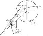
平面M为水下摄像机的像素平面,平面N为标定盘盘面所在平面,O为水下摄像机光心,A为像素平面内的像素坐标原点,点B为标定盘的圆心,点P为标定盘上的一个标定点,


其中,in,


其中,S为尺度因子,表示该图像显示的缩放比例;


通过上式求得点


上述方案中,步骤S2中,修正比例K值计算公式如下:In the above scheme, in step S2, the calculation formula of the correction ratio K value is as follows:

其中,


上述方案中,步骤S4的光心校正方法如下:In the above scheme, the optical center correction method of step S4 is as follows:
(1)在像素平面内建立像素坐标系XAY,A为像素坐标原点,标定点P在旋转过程中在像素坐标系下的投影轨迹中,当K取最大值时,离点A最远的点为


(2)调整水下摄像机的位置,将标定盘圆心B的投影调节到像素坐标系的
(3)对Cx,Cy值进行如下修正:(3) Correct the Cx and Cy values as follows:


上述方案中,步骤S6中,通过曲线K(D)实现畸变校正的方法如下:In the above scheme, in step S6, the method for realizing distortion correction through the curve K(D) is as follows:
通过曲线K(D)把某一畸变点


其中in

对于分辨率为M*N的图像从坐标为(1,1)的像素开始依次遍历图像中所有像素点,并通过式(7)计算各个像素点的新坐标
通过上述技术方案,本发明提供的一种水下摄像机图像径向畸变校正装置及方法具有如下有益效果:Through the above technical solutions, the apparatus and method for correcting radial distortion of an underwater camera image provided by the present invention have the following beneficial effects:
1、本发明设计了一套校正装置置于水下,通过控制标定盘自动旋转可以测量同一个标定点在不同角度下的K值,通过数据拟合可以得到该标定点处的K均值;1. The present invention designs a set of calibration devices to be placed underwater, and the K value of the same calibration point at different angles can be measured by controlling the automatic rotation of the calibration disk, and the K mean value at the calibration point can be obtained through data fitting;
2、本发明通过设置多个标定点,通过同样的方法可以得到多个标定点在不同角度下的K值,通过四阶曲线拟合,得到像素平面内通用曲线K(D)的表达式;2. In the present invention, by setting a plurality of calibration points, the K values of the plurality of calibration points at different angles can be obtained by the same method, and the expression of the general curve K(D) in the pixel plane is obtained through fourth-order curve fitting;
3、本发明通过上述方法可以提高标定的自动化程度和标定结果的精确性。3. The present invention can improve the automation degree of calibration and the accuracy of calibration results through the above method.
附图说明Description of drawings
为了更清楚地说明本发明实施例或现有技术中的技术方案,下面将对实施例或现有技术描述中所需要使用的附图作简单地介绍。In order to illustrate the embodiments of the present invention or the technical solutions in the prior art more clearly, the following briefly introduces the accompanying drawings that are required in the description of the embodiments or the prior art.
图1为径向畸变的示意图,(a)为正常图像,(b)为桶形失真,(c)为枕形失真;Figure 1 is a schematic diagram of radial distortion, (a) is a normal image, (b) is barrel distortion, and (c) is pincushion distortion;
图2为本发明实施例所公开的一种水下摄像机图像径向畸变校正装置示意图;2 is a schematic diagram of a device for correcting radial distortion of an underwater camera image disclosed in an embodiment of the present invention;
图3为本发明的水下摄像机图像径向畸变校正方法流程图;Fig. 3 is the flow chart of the radial distortion correction method of underwater camera image of the present invention;
图4为摄像机径向畸变映射示意图;FIG. 4 is a schematic diagram of the radial distortion mapping of the camera;
图5为光心校正示意图;Fig. 5 is a schematic diagram of optical center correction;
图6为K1拟合曲线;Fig. 6 is K1 fitting curve;
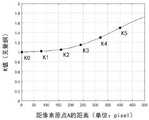
图7为多点K值拟合示意图。Figure 7 is a schematic diagram of multi-point K value fitting.
图中,1、底座一;2、底座二;3、滑动轴;4、标尺;5、水下摄像机;6、伺服电机;7、转轴;8、标定盘;9、标定点;10、竖杆;11、横梁;12、滑块;13、支撑杆;14、支架;15、光轴。In the figure, 1, base one; 2, base two; 3, sliding shaft; 4, ruler; 5, underwater camera; 6, servo motor; 7, rotating shaft; 8, calibration plate; 9, calibration point; 10, vertical rod; 11, beam; 12, slider; 13, support rod; 14, bracket; 15, optical axis.
具体实施方式Detailed ways
下面将结合本发明实施例中的附图,对本发明实施例中的技术方案进行清楚、完整地描述。The technical solutions in the embodiments of the present invention will be clearly and completely described below with reference to the accompanying drawings in the embodiments of the present invention.
本发明提供了一种水下摄像机5图像径向畸变校正装置,如图2所示,包括通过滑动轴3连接的底座一1和底座二2,滑动轴3上设置标尺4。底座一1和底座二2可以在滑动轴3上移动,进而调整两者之间的距离。通过标尺4可以测得两者之间的距离。底座一1上安装有可上下升降和左右移动的水下摄像机5,底座二2上安装有伺服电机6,伺服电机6通过转轴7连接标定盘8,标定盘8上设置有5个标定点9,标定点9为红色发光二极管,5个标定点9均匀分布于过标定盘8圆心B的一个半径上,5个标定点9距离圆心的距离分别为80mm、160mm、240mm、320mm、400mm。水下摄像机5的光轴15正对标定盘8。该水下摄像机5的回传图像分辨率为800*600,焦距20mm。The present invention provides an image radial distortion correction device of an
具体的,底座一1上安装有两根竖杆10,两根竖杆10之间通过螺栓安装一根横梁11,横梁11上安装有滑块12,水下摄像机5安装于滑块12上,通过调整滑块12可以调整水下摄像机5在横梁11上的水平位置,通过调整横梁11在竖杆10上的位置,可以调整水下摄像机5的高度。Specifically, two
伺服电机6通过支撑杆13安装于底座二2上,底座二2上还设置有支架14,支架14上端有弧形凹槽,转轴7架设于支架14上的弧形凹槽内。当伺服电机6旋转时,可以通过转轴7带动标定盘8以圆心为轴旋转。The
一种水下摄像机5图像径向畸变校正方法,采用上述的水下摄像机5图像径向畸变校正装置,如图3所示,包括如下步骤:A method for correcting radial distortion of an image of an
S1:调整底座一1和底座二2之间的距离,使得标定盘8在旋转过程中能够完整出现在水下摄像机5的视野范围内,调整水下摄像机5位置使其光轴15正对标定盘8圆心,然后将校正装置置于水下;S1: Adjust the distance between the base one 1 and the base two 2, so that the calibration disk 8 can completely appear in the field of view of the
S2:如图4所示,平面M为水下摄像机5的像素平面,即水下摄像机5镜头平面,平面上的投影点由像素坐标表示;平面N为标定盘8盘面所在平面,该平面上的标定点9由摄像机坐标表示。图4中,O为水下摄像机5光心,A为像素平面内的像素坐标原点,点B为标定盘8的圆心,点P为标定盘8上的一个标定点9,
开始测试时,控制伺服电机6将标定盘8上的标定点9连线处于方位0°位置,选择第一个标定点9,系统自动采集其像素坐标,并将像素坐标转换为水下摄像机5坐标,计算得到该标定点9在方位为0°下的修正比例K1值;When starting the test, control the
将像素坐标转换为水下摄像机5坐标的方法如下:The method to convert pixel coordinates to
平面M为水下摄像机5的像素平面,平面N为标定盘8盘面所在平面,O为水下摄像机5光心,A为像素平面内的像素坐标原点,点B为标定盘8的圆心,点P为标定盘8上的一个标定点,


其中,in,


其中,S为尺度因子,表示该图像显示的缩放比例;


通过上式求得点


修正比例K值计算公式如下:The formula for calculating the correction ratio K value is as follows:

其中,


S3:系统控制伺服电机6沿顺/逆时针旋转一定角度,重复步骤S2,得到该标定点9在该角度下的K1值;循环此过程至标定点9回到0°位置,得到该标定点9在不同角度下的多组K1值,并通过均值拟合方式计算该标定点9处的K1均值;S3: The system controls the
S4:根据K1的最大值与最小值的偏差,如果偏差在设定阈值范围内,则不需进行光心校正,如果超出设定阈值,则进行光心校正;S4: According to the deviation between the maximum value and the minimum valueof K1, if the deviation is within the range of the set threshold, the optical center correction is not required, and if it exceeds the set threshold, the optical center correction is performed;
光心校正方法如下:The optical center correction method is as follows:
(1)如图5所示,在像素平面内建立像素坐标系XAY,A为像素坐标原点,标定点9P在旋转过程中在像素坐标系下的投影轨迹中,当K取最大值时,离点A最远的点为


如果四点不共线,说明该水下摄像机镜头存在切向畸变,切向畸变是摄像机镜头的物理缺陷,存在切向畸变的水下摄像机无法用于定量观测。If the four points are not collinear, it means that the underwater camera lens has tangential distortion, which is a physical defect of the camera lens, and the underwater camera with tangential distortion cannot be used for quantitative observation.
(2)调整水下摄像机5的位置,将标定盘8圆心B的投影调节到像素坐标系的
(3)对Cx,Cy值进行如下修正:(3) Correct the Cx and Cy values as follows:


S5:选择第二个标定点9,重复步骤S2-S4,得到第二个标定点9的K2均值;重复此过程,得到第n个标定点9的Kn均值;将n个标定点9的K值进行四阶曲线拟合,得到像素平面内通用曲线K(D)的表达式,D为成像点距离像素坐标原点A的距离。S5: Select the second calibration point 9, repeat steps S2-S4 to obtain the K2 mean value of the second calibration point 9; repeat this process to obtain the Kn mean value of the nth calibration point 9; The fourth-order curve fitting is performed on the K value of , and the expression of the general curve K(D) in the pixel plane is obtained, where D is the distance between the imaging point and the pixel coordinate origin A.
实际操作中,标定点可取多于五个,标定点越多,用于拟合的K值越多,越容易得到更加准确的曲线。当标定点只有五个时,曲线拟合的阶数不应太大,应控制在2~4阶。随着标定点数量的增加,可以适当增加曲线拟合阶数从而得到更好的拟合结果。曲线拟合横坐标的取值范围根据待校正水下摄像机图像分辨率确定,如果分辨率为M*N,则D的取值范围是
S6:利用K(D)表达式对水下摄像机5拍摄的水下图像进行径向畸变校正,校正的方法如下:S6: Use the K(D) expression to perform radial distortion correction on the underwater image captured by the
通过曲线K(D)把某一畸变点


其中in

对于分辨率为M*N的图像从坐标为(1,1)的像素开始依次遍历图像中所有像素点,并通过式(7)计算各个像素点的新坐标
实施例1Example 1
如图2所示,将待校正水下摄像机通过螺栓固定在滑块上。该水下摄像机的回传图像分辨率为800*600,焦距20mm。在标定盘上,距离标定盘圆心B分别为80mm、160mm、240mm、320mm、400mm处各设置1个红灯作为标定点,5个标定点与标定盘圆心共线,红灯需要能够在水下工作。通过滑动轴的滑动同时读取标尺读数调节底座一的位置,使待校正水下摄像机镜头平面与标定盘平面的水平距离为430mm。通过滑块和横梁位置使待校正水下摄像机的光轴正对标定盘圆心B,即标定盘圆心在图像中处于(400,300)坐标处。将整个装置置于水中。As shown in Figure 2, the underwater camera to be calibrated is fixed on the slider by bolts. The resolution of the returned image of the underwater camera is 800*600, and the focal length is 20mm. On the calibration plate, one red light is set as the calibration point at the distances of 80mm, 160mm, 240mm, 320mm, and 400mm from the center B of the calibration plate. The 5 calibration points are collinear with the center of the calibration plate. Work. Adjust the position of base 1 by reading the scale reading while sliding the sliding shaft, so that the horizontal distance between the lens plane of the underwater camera to be calibrated and the plane of the calibration plate is 430mm. Through the position of the slider and the beam, the optical axis of the underwater camera to be calibrated is aligned with the center B of the calibration disk, that is, the center of the calibration disk is at (400,300) coordinates in the image. Place the entire device in water.
开启测试,此时标定盘上的标定点连线处于方位0°位置,距离圆心80mm的标定点红灯亮起,系统自动采集标定点像素坐标为(400,248),通过式(1)将像素坐标转换为摄像机坐标:首先将其转换为坐标原点在图像中心的坐标为(0,52),再通过式(2)(3)计算得到该点对应的标定盘处摄像机坐标为(0,78),因此求得距离为80mm点在方位为0°下的K值为1.025。系统将该点方位0°、该点像素坐标(0,52)、该点K值1.025记录在缓存中。系统控制伺服电机沿顺时针旋转1°,并通过上述过程记录该标定点在方位1°的数据。循环此过程至标定点连线方位回到0°位置,可得到该标定点0°~359°对应的360组数据。系统按照图6方式通过均值拟合方式计算该标定点(距离为80mm)处点集的K1均值为1.02(图中虚线所示)。图6中,横坐标表示标定点的方位,纵坐标表示对应于各个方位K1值的大小。从图6可以看出,K1值在0°到360°方位下会产生小幅波动,这是由误差引起的。可通过加权均值方式计算该K1值曲线的拟合K1值,来表征该水下摄像机像素坐标系中满足距离为
由上述过程得到了第一个标定点(80mm)的K1值为1.02,关闭该红灯并将距离标定盘中心160mm的第二个标定点红灯点亮,重复上述0°~359°标定过程,得到第二个标定点(160mm)的K2均值为1.05。依次重复上述过程可分别得到第三个标定点(240mm)K3均值为1.15,第四个标定点(320mm)K4均值为1.3,第五个标定点(400mm)K5均值为1.5。系统通过(0,0),(80,1.02),(160,1.05),(240,1.15),(320,1.3),(400,1.5)六个点做四阶曲线拟合,得到像素平面内通用K值曲线K(D)多项式为:The K1 value of the first calibration point (80mm) is obtained from the above process to be 1.02, turn off the red light and turn on the red light of the second calibration point 160mm away from the center of the calibration disk, repeat the above 0°~359° calibration process, the K2 mean value of the second calibration point (160mm) is 1.05. Repeat the above process in turn to obtain the average value of K3 for the third calibration point (240mm) is 1.15, the average value of K4 for the fourth calibration point (320mm) is 1.3, and the average value of K5 for the fifth calibration point (400mm) is 1.5. The system performs fourth-order curve fitting through six points (0,0), (80,1.02), (160,1.05), (240,1.15), (320,1.3), (400,1.5) to obtain the pixel plane The internal general K value curve K(D) polynomial is:

拟合曲线见图7,图7中,横坐标表示成像点距离像素坐标原点A的距离D,单位为像素(pixel),纵坐标表示K值大小。K0为原点处K值,当D=0时即原点投影的K值为1,表示此处无畸变;K1到K5分别是对应五个标定点的K值,通过图7可以看出,K值随D的增加呈非线性增大,这与水下摄像机径向畸变趋势相符。通过曲线拟合可以得到曲线K(D),它表示在D为0到500区间内任意点的K值。通过拟合曲线K(D),可以很容易的计算出整个图像范围内任意一点
水下摄像机径向畸变标定完成。The radial distortion calibration of the underwater camera is completed.
在水下摄像机使用中,拍摄到了一幅分辨率为800*600的图像,从左上角第一个像素(1,1)开始,通过式(8)求该点与中心点(400,300)间的距离D=499pixel,通过K(D)表达式(9)求出该点K值为1.72,通过式(7)求得该点校正坐标为(-286,-214)该坐标表示校正后的像素点(1,1)所在的像素坐标,系统自动将该点的图像信息转移到一个新的图像矩阵下。由于K>1因此图像在畸变校正后发生了延展,分辨率会增大。系统通过上述方式遍历该图像的所有像素点,生成了一个新的图像矩阵,并对未填充的矩阵单元使用插值方式插入图像信息,就生成了校正后的图像。该图像能正确反映水下物体的真实位置的投影信息,可用于水下物体位置的定量测量。In the use of the underwater camera, an image with a resolution of 800*600 is captured. Starting from the first pixel (1,1) in the upper left corner, the distance between this point and the center point (400,300) is calculated by formula (8). The distance D=499pixel, the K value of this point is 1.72 obtained by K(D) expression (9), and the corrected coordinate of this point is obtained by formula (7) as (-286,-214) This coordinate represents the corrected pixel The pixel coordinates where the point (1,1) is located, the system automatically transfers the image information of the point to a new image matrix. Since K>1, the image is stretched after distortion correction, and the resolution is increased. The system traverses all the pixels of the image through the above method, generates a new image matrix, and uses interpolation to insert the image information for the unfilled matrix elements to generate the corrected image. The image can correctly reflect the projection information of the real position of the underwater object, and can be used for quantitative measurement of the position of the underwater object.
实施例2Example 2
如图2所示,将待校正水下摄像机通过螺栓固定在滑块上。该水下摄像机的回传图像分辨率为800*600,焦距20mm。在标定盘上,距离标定盘圆心B分别为80mm、160mm、240mm、320mm、400mm处各设置1个红灯作为标定点,5个标定点与标定盘圆心共线,红灯需要能够在水下工作。通过滑动轴的滑动同时读取标尺读数调节底座一的位置,使待校正水下摄像机镜头平面与标定盘平面的水平距离为430mm。通过滑块和横梁位置使待校正水下摄像机的光轴正对标定盘圆心B,即标定盘圆心在图像中处于(400,300)坐标处。将整个装置置于水中。As shown in Figure 2, the underwater camera to be calibrated is fixed on the slider by bolts. The resolution of the returned image of the underwater camera is 800*600, and the focal length is 20mm. On the calibration plate, one red light is set as the calibration point at the distances of 80mm, 160mm, 240mm, 320mm, and 400mm from the center B of the calibration plate. The 5 calibration points are collinear with the center of the calibration plate. Work. Adjust the position of base 1 by reading the scale reading while sliding the sliding shaft, so that the horizontal distance between the lens plane of the underwater camera to be calibrated and the plane of the calibration plate is 430mm. Through the position of the slider and the beam, the optical axis of the underwater camera to be calibrated is aligned with the center B of the calibration disk, that is, the center of the calibration disk is at (400,300) coordinates in the image. Place the entire device in water.
开启测试,此时标定盘上的标定点连线处于方位0°位置,距离圆心80mm的标定点红灯亮起,系统自动采集标定点像素坐标为(400,248),通过式(1)将像素坐标转换为摄像机坐标:首先将其转换为坐标原点在图像中心的坐标为(0,52),再通过式(2)(3)计算得到该点对应的标定盘处摄像机坐标为(0,78),因此求得距离为80mm点在方位为0°下的K值为1.025。系统将该点方位0°、该点像素坐标(0,52)、该点K值1.025记录在缓存中。系统控制伺服电机沿顺时针旋转1°,并通过上述过程记录该标定点在方位1°的数据。循环此过程至标定点连线方位回到0°位置,可得到该标定点0°~359°对应的360组数据。系统按照图6方式通过均值拟合方式计算该标定点(距离为80mm)处点集的K1均值为1.02。根据K值与方位的关系,得到的K1值最大值和最小值偏差不大,证明该水下摄像机镜头不存在光心偏移,无需进行光心校正。Start the test. At this time, the calibration point connection line on the calibration disk is at the
由上述过程得到了第一个标定点(80mm)的K1值为1.02,关闭该红灯并将距离标定盘中心160mm的第二个标定点红灯点亮,重复上述0°~359°标定过程,得到第二个标定点(160mm)的K2均值为1.05。依次重复上述过程可分别得到第三个标定点(240mm)K3均值为1.15,第四个标定点(320mm)K4均值为1.3,但K4值曲线的最大值为1.35,最小值为1.27,此时计算此时D为213,光心偏移阈值10/D=0.047,因此K4值最大值偏移量0.05超过阈值0.047,所以存在光心偏移。通过查询K4值曲线最大值点


水下摄像机径向畸变标定完成。The radial distortion calibration of the underwater camera is completed.
在水下摄像机使用中,拍摄到了一幅分辨率为800*600的图像,从左上角第一个像素(1,1)开始,通过式(8)求该点与中心点(412,291)间的距离D=504pixel,通过K(D)表达式(10)求出该点K值为1.73,通过式(7)求得该点校正坐标为(-299,-210) ,该坐标表示校正后的像素点(1,1)所在的像素坐标,系统自动将该点的图像信息转移到一个新的图像矩阵下。由于K>1因此图像在畸变校正后发生了延展,分辨率会增大。In the use of the underwater camera, an image with a resolution of 800*600 is captured. Starting from the first pixel (1,1) in the upper left corner, the distance between this point and the center point (412,291) is calculated by formula (8). The distance D=504pixel, the K value of the point is 1.73 by the K(D) expression (10), and the correction coordinates of the point are (-299,-210) obtained by the formula (7), which represents the corrected coordinates. The pixel coordinate where the pixel point (1,1) is located, the system automatically transfers the image information of this point to a new image matrix. Since K>1, the image is stretched after distortion correction, and the resolution is increased.
系统通过上述方式遍历该图像的所有像素点,生成了一个新的图像矩阵,并对未填充的矩阵单元使用插值方式插入图像信息,就生成了校正后的图像。该图像能正确反映水下物体的真实位置的投影信息,可用于水下物体位置的定量测量。The system traverses all the pixels of the image through the above method, generates a new image matrix, and uses interpolation to insert the image information for the unfilled matrix elements to generate the corrected image. The image can correctly reflect the projection information of the real position of the underwater object, and can be used for quantitative measurement of the position of the underwater object.
本发明所述水下摄像机图像径向畸变校正装置和方法,其标定过程应在水中完成。因为所述校正装置组成配件均可找到能在水下使用的型号,因此不存在组装和实现难度。本发明装置和方法所用到的图像类算法,包括根据图像内容识别标定点并得到该点的像素坐标、图像像素点的遍历、插值和裁剪均为计算机图像处理常用方法,在系统实现过程中不存在难度。该装置和方法同样适用于空气中使用的摄像机径向畸变校正,对于空气中使用的摄像机径向畸变校正过程与水下摄像机完全相同,校正过程需要在空气中完成。According to the apparatus and method for correcting radial distortion of underwater camera images of the present invention, the calibration process should be completed in water. Because the components of the calibration device can all find models that can be used underwater, there is no difficulty in assembly and implementation. The image-like algorithms used in the device and method of the present invention, including identifying the calibration point according to the image content and obtaining the pixel coordinates of the point, traversing, interpolation and cropping of the image pixel points are commonly used methods for computer image processing. Difficulty exists. The device and method are also applicable to the radial distortion correction of the camera used in the air. The radial distortion correction process of the camera used in the air is exactly the same as that of the underwater camera, and the correction process needs to be completed in the air.
对所公开的实施例的上述说明,使本领域专业技术人员能够实现或使用本发明。对这些实施例的多种修改对本领域的专业技术人员来说将是显而易见的,本文中所定义的一般原理可以在不脱离本发明的精神或范围的情况下,在其它实施例中实现。因此,本发明将不会被限制于本文所示的这些实施例,而是要符合与本文所公开的原理和新颖特点相一致的最宽的范围。The above description of the disclosed embodiments enables any person skilled in the art to make or use the present invention. Various modifications to these embodiments will be readily apparent to those skilled in the art, and the generic principles defined herein may be implemented in other embodiments without departing from the spirit or scope of the invention. Thus, the present invention is not intended to be limited to the embodiments shown herein, but is to be accorded the widest scope consistent with the principles and novel features disclosed herein.
Claims (6)
Translated fromChinese


Priority Applications (1)
| Application Number | Priority Date | Filing Date | Title |
|---|---|---|---|
| CN202210541076.XACN114640781B (en) | 2022-05-19 | 2022-05-19 | A device and method for correcting radial distortion of underwater camera images |
Applications Claiming Priority (1)
| Application Number | Priority Date | Filing Date | Title |
|---|---|---|---|
| CN202210541076.XACN114640781B (en) | 2022-05-19 | 2022-05-19 | A device and method for correcting radial distortion of underwater camera images |
Publications (2)
| Publication Number | Publication Date |
|---|---|
| CN114640781A CN114640781A (en) | 2022-06-17 |
| CN114640781Btrue CN114640781B (en) | 2022-08-23 |
Family
ID=81953384
Family Applications (1)
| Application Number | Title | Priority Date | Filing Date |
|---|---|---|---|
| CN202210541076.XAActiveCN114640781B (en) | 2022-05-19 | 2022-05-19 | A device and method for correcting radial distortion of underwater camera images |
Country Status (1)
| Country | Link |
|---|---|
| CN (1) | CN114640781B (en) |
Families Citing this family (1)
| Publication number | Priority date | Publication date | Assignee | Title |
|---|---|---|---|---|
| CN117630045B (en)* | 2024-01-17 | 2024-11-26 | 北京京瀚禹电子工程技术有限公司 | A chip screening and anti-detection system based on machine vision |
Citations (6)
| Publication number | Priority date | Publication date | Assignee | Title |
|---|---|---|---|---|
| WO2016070318A1 (en)* | 2014-11-04 | 2016-05-12 | SZ DJI Technology Co., Ltd. | Camera calibration |
| CN105678742A (en)* | 2015-12-29 | 2016-06-15 | 哈尔滨工业大学深圳研究生院 | Underwater camera calibration method |
| CN110807815A (en)* | 2019-10-30 | 2020-02-18 | 扬州大学 | Fast underwater calibration method based on two sets of mutually orthogonal parallel lines corresponding to vanishing points |
| CN113137920A (en)* | 2021-05-19 | 2021-07-20 | 重庆大学 | Underwater measurement equipment and underwater measurement method |
| CN113960564A (en)* | 2021-09-17 | 2022-01-21 | 上海大学 | A laser comprehensive reference system for underwater detection and a method for ranging and calibration |
| CN114326258A (en)* | 2020-09-25 | 2022-04-12 | 山东省科学院海洋仪器仪表研究所 | An underwater camera device and its adjustment method |
Family Cites Families (3)
| Publication number | Priority date | Publication date | Assignee | Title |
|---|---|---|---|---|
| CN109040741A (en)* | 2018-06-15 | 2018-12-18 | 上海应用技术大学 | A kind of calibration and test device and method for NI Vision Builder for Automated Inspection |
| CN110033491B (en)* | 2019-04-15 | 2023-07-28 | 南京工程学院 | Camera calibration method |
| CN113841384B (en)* | 2019-05-23 | 2023-07-25 | 索尼互动娱乐股份有限公司 | Calibration devices, charts and calibration methods for calibration |
- 2022
- 2022-05-19CNCN202210541076.XApatent/CN114640781B/enactiveActive
Patent Citations (7)
| Publication number | Priority date | Publication date | Assignee | Title |
|---|---|---|---|---|
| WO2016070318A1 (en)* | 2014-11-04 | 2016-05-12 | SZ DJI Technology Co., Ltd. | Camera calibration |
| CN105981074A (en)* | 2014-11-04 | 2016-09-28 | 深圳市大疆创新科技有限公司 | Camera calibration |
| CN105678742A (en)* | 2015-12-29 | 2016-06-15 | 哈尔滨工业大学深圳研究生院 | Underwater camera calibration method |
| CN110807815A (en)* | 2019-10-30 | 2020-02-18 | 扬州大学 | Fast underwater calibration method based on two sets of mutually orthogonal parallel lines corresponding to vanishing points |
| CN114326258A (en)* | 2020-09-25 | 2022-04-12 | 山东省科学院海洋仪器仪表研究所 | An underwater camera device and its adjustment method |
| CN113137920A (en)* | 2021-05-19 | 2021-07-20 | 重庆大学 | Underwater measurement equipment and underwater measurement method |
| CN113960564A (en)* | 2021-09-17 | 2022-01-21 | 上海大学 | A laser comprehensive reference system for underwater detection and a method for ranging and calibration |
Non-Patent Citations (4)
| Title |
|---|
| Underwater camera model and its use in calibration;Longxiang Huang等;《2015 IEEE International Conference on Information and Automation》;20151001;全文* |
| 水下摄像机标定技术的研究;李洪生;《中国优秀硕士学位论文全文数据库》;20150315;全文* |
| 水下视觉SLAM相机成像畸变纠正研究;张阳等;《海洋技术学报》;20191215(第06期);全文* |
| 水电枢纽水下摄像数据的畸变机理及标定研究;李永龙等;《自动化与仪表》;20191225(第12期);全文* |
Also Published As
| Publication number | Publication date |
|---|---|
| CN114640781A (en) | 2022-06-17 |
Similar Documents
| Publication | Publication Date | Title |
|---|---|---|
| CN108921901B (en) | A large field of view camera calibration method based on precision two-axis turntable and laser tracker | |
| CN109632103B (en) | High-altitude building temperature distribution and surface crack remote monitoring system and monitoring method | |
| JP7541194B2 (en) | Method and apparatus for detecting diameter of single crystal silicon based on chord length ratio of concentric ellipses | |
| CN108326850A (en) | A kind of accurate mobile mechanical arm of robot reaches the method and system of designated position | |
| CN106971408A (en) | A kind of camera marking method based on space-time conversion thought | |
| CN114640781B (en) | A device and method for correcting radial distortion of underwater camera images | |
| CN115187612A (en) | Plane area measuring method, device and system based on machine vision | |
| CN114061472B (en) | Method for correcting measurement coordinate error based on target | |
| CN112598747A (en) | Combined calibration method for monocular camera and projector | |
| CN115115550A (en) | A method and device for image perspective correction based on camera perspective transformation | |
| CN113781581A (en) | Depth of field distortion model calibration method based on target loose attitude constraint | |
| CN109883399A (en) | An Alternate Approach Algorithm for Overlapping Multi-slice Photogrammetry Based on Focal Length Correction | |
| CN115290008B (en) | An Algorithm for Angle Calibration of Collimator in Image Measurement | |
| CN119413097B (en) | Structure quasi-static deformation monitoring method, system, terminal and readable storage medium based on zoom imaging | |
| CN116222968A (en) | A Calibration System and Method for a Dual Optical Wedge Scanner Based on the Principle of Directional Decoupling | |
| CN107976146B (en) | Self-calibration method and measurement method of linear array CCD camera | |
| CN118279411B (en) | Leveling alignment calibration method in image sensor AA process | |
| CN110689582B (en) | Camera Calibration Method of Total Station | |
| CN108898585B (en) | Shaft part detection method and device | |
| CN115482276A (en) | High-precision calibration method based on phase shift deflection measurement system | |
| CN113421300B (en) | Method and device for determining actual position of object in fisheye camera image | |
| CN116061196A (en) | Method and system for calibrating kinematic parameters of multi-axis motion platform | |
| CN104764416B (en) | A kind of method for measuring dynamic rotation body ovality | |
| CN110567437B (en) | Photographic measuring method for port hoisting machinery | |
| CN111780683A (en) | Portable scanning system and method of use |
Legal Events
| Date | Code | Title | Description |
|---|---|---|---|
| PB01 | Publication | ||
| PB01 | Publication | ||
| SE01 | Entry into force of request for substantive examination | ||
| SE01 | Entry into force of request for substantive examination | ||
| GR01 | Patent grant | ||
| GR01 | Patent grant |