CN114634303A - Preform manufacturing process and optical fiber - Google Patents
Preform manufacturing process and optical fiberDownload PDFInfo
- Publication number
- CN114634303A CN114634303ACN202210172804.4ACN202210172804ACN114634303ACN 114634303 ACN114634303 ACN 114634303ACN 202210172804 ACN202210172804 ACN 202210172804ACN 114634303 ACN114634303 ACN 114634303A
- Authority
- CN
- China
- Prior art keywords
- guide
- sleeve
- arc
- manufacturing process
- casing
- Prior art date
- Legal status (The legal status is an assumption and is not a legal conclusion. Google has not performed a legal analysis and makes no representation as to the accuracy of the status listed.)
- Pending
Links
- 238000004519manufacturing processMethods0.000titleclaimsabstractdescription24
- 239000013307optical fiberSubstances0.000titleclaimsabstractdescription8
- 239000011521glassSubstances0.000claimsabstractdescription19
- 238000001514detection methodMethods0.000claimsdescription22
- 239000004809TeflonSubstances0.000claimsdescription3
- 229920006362Teflon®Polymers0.000claimsdescription3
- 238000000034methodMethods0.000description4
- 238000005491wire drawingMethods0.000description4
- 238000005452bendingMethods0.000description1
- 230000009286beneficial effectEffects0.000description1
- 230000005540biological transmissionEffects0.000description1
- 238000010586diagramMethods0.000description1
- 238000012681fiber drawingMethods0.000description1
- 230000002452interceptive effectEffects0.000description1
- 239000000463materialSubstances0.000description1
- 238000009417prefabricationMethods0.000description1
- 230000009466transformationEffects0.000description1
Images


Classifications
- C—CHEMISTRY; METALLURGY
- C03—GLASS; MINERAL OR SLAG WOOL
- C03B—MANUFACTURE, SHAPING, OR SUPPLEMENTARY PROCESSES
- C03B37/00—Manufacture or treatment of flakes, fibres, or filaments from softened glass, minerals, or slags
- C03B37/01—Manufacture of glass fibres or filaments
- C03B37/012—Manufacture of preforms for drawing fibres or filaments
- C03B37/01205—Manufacture of preforms for drawing fibres or filaments starting from tubes, rods, fibres or filaments
- C03B37/01211—Manufacture of preforms for drawing fibres or filaments starting from tubes, rods, fibres or filaments by inserting one or more rods or tubes into a tube
- C—CHEMISTRY; METALLURGY
- C03—GLASS; MINERAL OR SLAG WOOL
- C03B—MANUFACTURE, SHAPING, OR SUPPLEMENTARY PROCESSES
- C03B37/00—Manufacture or treatment of flakes, fibres, or filaments from softened glass, minerals, or slags
- C03B37/01—Manufacture of glass fibres or filaments
- C03B37/02—Manufacture of glass fibres or filaments by drawing or extruding, e.g. direct drawing of molten glass from nozzles; Cooling fins therefor
- C03B37/025—Manufacture of glass fibres or filaments by drawing or extruding, e.g. direct drawing of molten glass from nozzles; Cooling fins therefor from reheated softened tubes, rods, fibres or filaments, e.g. drawing fibres from preforms
- C03B37/027—Fibres composed of different sorts of glass, e.g. glass optical fibres
Landscapes
- Engineering & Computer Science (AREA)
- Chemical & Material Sciences (AREA)
- Life Sciences & Earth Sciences (AREA)
- General Life Sciences & Earth Sciences (AREA)
- Geochemistry & Mineralogy (AREA)
- Manufacturing & Machinery (AREA)
- Materials Engineering (AREA)
- Organic Chemistry (AREA)
- Manufacture, Treatment Of Glass Fibers (AREA)
Abstract
Translated fromChinese
Description
Translated fromChinese技术领域technical field
本发明涉及光纤预制棒领域,具体涉及预制棒的制造工艺以及光纤。The invention relates to the field of optical fiber preforms, in particular to a manufacturing process of the preforms and optical fibers.
背景技术Background technique
套管法具有生产效率高、成本低的特点。实际操作时,会在套管的一端熔接尾管,将芯棒通过尾管插入套管内,最终通过插入尾管的玻璃棒顶住最外侧的芯棒形成预制棒,然后将由套管和芯棒组合而成的预制棒送至拉丝炉上进行拉丝,拉丝时,拉丝炉上方的夹紧装置夹紧尾管。The casing method has the characteristics of high production efficiency and low cost. In actual operation, the tail pipe will be welded at one end of the sleeve, the mandrel will be inserted into the sleeve through the tail pipe, and finally a preform will be formed by the glass rod inserted into the tail pipe against the outermost mandrel, and then the sleeve and the mandrel will be formed. The assembled preform is sent to the wire drawing furnace for wire drawing. During wire drawing, the clamping device above the wire drawing furnace clamps the tail pipe.
实际生产中,都是水平插入芯棒,芯棒和套管内侧壁之间滑动摩擦,这种方式非常容易划伤芯棒外侧壁以及套管的内侧壁,最终影响光纤拉丝质量。In actual production, the mandrel is inserted horizontally, and there is sliding friction between the mandrel and the inner side wall of the sleeve. This method is very easy to scratch the outer side wall of the mandrel and the inner side wall of the sleeve, which ultimately affects the quality of fiber drawing.
发明内容SUMMARY OF THE INVENTION
本发明针对上述问题,提出了预制棒的制造工艺以及光纤。In view of the above problems, the present invention proposes a manufacturing process of a preform and an optical fiber.
本发明采取的技术方案如下:The technical scheme adopted by the present invention is as follows:
一种预制棒的制造工艺,包括以下步骤:A manufacturing process of a preform, comprising the following steps:
(1)使导向件插入熔接有尾管的套管上,所述导向件包括位于尾管内的导向部以及位于套管内的弧形支撑部,且弧形支撑部位于套管内侧壁的最下方;(1) Insert a guide member into the sleeve where the tail pipe is welded, the guide member includes a guide part located in the tail pipe and an arc-shaped support part located in the sleeve, and the arc-shaped support part is located at the bottom of the inner side wall of the sleeve ;
(2)将设定数量的芯棒依次通过导向部后插入套管中,且最外端的芯棒通过玻璃棒顶入,各芯棒在弧形支撑部上滑动,直至最里端的芯棒滑动至套管底部;(2) Insert the set number of mandrel rods into the sleeve through the guide part in turn, and the outermost mandrel rod is pushed in through the glass rod, and each mandrel rod slides on the arc-shaped support part until the innermost mandrel rod slides to the bottom of the casing;
(3)移除玻璃棒,将套管转动设定角度,使芯棒不再压住弧形支撑部;(3) Remove the glass rod, and turn the sleeve to a set angle, so that the core rod no longer presses the arc-shaped support;
(4)将导向件从套管中移出;(4) Remove the guide from the casing;
(5)重新插入玻璃棒,使玻璃棒顶住最外端的芯棒,得到预制棒。(5) Reinsert the glass rod so that the glass rod can withstand the outermost mandrel to obtain a preform.
本申请的制造工艺通过伸入套管内的弧形支撑部,能够有效防止芯棒与套管之间直接接触摩擦,通过防止芯棒和套管的划伤,有效保证了预制棒的质量;弧形支撑部的设计,使得在芯棒插入后,通过转动设定角度使芯棒不再压住弧形支撑部后,能够较为方便的将导向件水平移出。The manufacturing process of the present application can effectively prevent the direct contact and friction between the mandrel and the sleeve through the arc-shaped support part extending into the sleeve, and effectively ensure the quality of the preform by preventing the mandrel and the sleeve from being scratched; The design of the arc-shaped support part makes it easier to move the guide horizontally out after the mandrel is inserted and the mandrel is no longer pressed against the arc-shaped support part by rotating the set angle.
于本发明其中一实施例中,所述设定角度为180°。转动180°后,使得弧形支撑部位于芯棒的上方。In one embodiment of the present invention, the set angle is 180°. After turning 180°, the arc-shaped support part is located above the mandrel.
于本发明其中一实施例中,所述导向部为管状结构,所述导向件的材质为特氟龙。In one embodiment of the present invention, the guide portion is a tubular structure, and the guide member is made of Teflon.
于本发明其中一实施例中,所述步骤1)~步骤4)通过组合装置实施,所述组合装置包括:In one embodiment of the present invention, the steps 1) to 4) are implemented by a combination device, and the combination device includes:
导向件,具有依次设置的管状的导向部以及弧形支撑部,所述导向部远离弧形支撑部的一端具有夹持环;a guide piece, which has a tubular guide part and an arc-shaped support part arranged in sequence, and one end of the guide part away from the arc-shaped support part has a clamping ring;
夹持限位机构,用于与所述导向件的夹持环配合,将导向件夹紧限定住;a clamping and limiting mechanism for cooperating with the clamping ring of the guide to clamp and limit the guide;
支撑辊组件,用于支撑套管并使套管绕自身轴线转动;The support roller assembly is used to support the casing and make the casing rotate around its own axis;
升降支撑机构,用于支撑套管并带动套管上下移动,在套管位于支撑辊组件上方时,通过升降支撑机构带动套管下移,使套管与支撑辊组件配合;以及a lifting support mechanism for supporting the casing and driving the casing to move up and down; when the casing is located above the support roller assembly, the lifting support mechanism drives the casing to move down, so that the casing is matched with the support roller assembly; and
移动机构,用于带动升降支撑机构和套管水平移动,使导向件插入套管内,且使套管位于支撑辊组件的上方。The moving mechanism is used to drive the lifting support mechanism and the sleeve to move horizontally, so that the guide is inserted into the sleeve and the sleeve is positioned above the support roller assembly.
组合装置的一种工作方式:夹持限位机构将导向件水平夹紧,将熔接有尾管的套管放入升降支撑机构上,通过移动机构带动升降支撑机构和套管水平移动,使套管移动至支撑辊组件的上方,移动的同时,导向件插入套管内,使弧形支撑部位于套管内侧壁的最下方,导向部位于尾管内,夹持环位于外管外部;通过人工或配套机械设备将设定数量的芯棒插入套管,最外端的芯棒通过玻璃棒顶入,完成后,取出玻璃棒,夹持限位机构不再夹持导向件,升降支撑机构带动套管下移,使套管与支撑辊组件配合,支撑辊组件带动套管和导向件转动设定角度(比如120°~180°),然后升降支撑机构带动套管上移,夹持限位机构重新夹紧导向件,移动机构工作,带动套管外移,从而导向件能够从套管内无压力的移出。A working method of the combined device: the clamping and limiting mechanism clamps the guide horizontally, and the sleeve with the tail pipe welded is placed on the lifting support mechanism, and the moving mechanism drives the lifting support mechanism and the sleeve to move horizontally, so that the sleeve can be moved horizontally. The tube moves to the top of the support roller assembly, and at the same time, the guide is inserted into the sleeve, so that the arc-shaped support part is located at the bottom of the inner side wall of the sleeve, the guide part is located in the tail pipe, and the clamping ring is located outside the outer pipe; The supporting mechanical equipment inserts the set number of mandrels into the casing, and the outermost mandrel is pushed in through the glass rod. After completion, the glass rod is taken out. The clamping limit mechanism no longer clamps the guide, and the lifting support mechanism drives the casing. Move down to make the sleeve fit with the support roller assembly, the support roller assembly drives the sleeve and the guide to rotate the set angle (for example, 120°~180°), and then the lifting support mechanism drives the sleeve to move up, and the clamping limit mechanism is reset. When the guide is clamped, the moving mechanism works to drive the casing to move outward, so that the guide can be moved out of the casing without pressure.
于本发明其中一实施例中,所述夹持限位机构包括分别设置在夹持环左右两端的夹持限位组件,所述夹持限位组件包括:In one embodiment of the present invention, the clamping and limiting mechanism includes clamping and limiting components respectively disposed at the left and right ends of the clamping ring, and the clamping and limiting components include:
移动架;mobile rack;
限位板,固定在移动架上;Limit plate, fixed on the mobile frame;
活动板,滑动安装在移动架上,与所述限位板配合,用于夹紧所述夹持环;a movable plate, which is slidably installed on the movable frame and cooperates with the limit plate for clamping the clamping ring;
第一伸缩元件,安装在移动架上,用于驱动所述活动板滑动;以及a first telescopic element, mounted on the moving frame, for driving the movable plate to slide; and
第一驱动元件,用于驱动移动架接近夹持环或远离夹持环。The first driving element is used for driving the moving frame to approach the clamping ring or away from the clamping ring.
通过第一伸缩元件能够夹紧或释放夹持环,通过第一驱动元件能够带动移动架移动,防止套管和导向件整体下移时与夹持限位组件干涉。The first telescopic element can clamp or release the clamping ring, and the first driving element can drive the moving frame to move, preventing interference with the clamping and limiting assembly when the sleeve and the guide piece move downward as a whole.
于本发明其中一实施例中,所述支撑辊组件包括两根平行设置的支撑辊以及用于驱动至少一根支撑辊转动的驱动电机。In one embodiment of the present invention, the supporting roller assembly includes two supporting rollers arranged in parallel and a driving motor for driving at least one supporting roller to rotate.
于本发明其中一实施例中,所述升降支撑机构包括升降元件以及固定在升降元件上的支撑件,所述支撑件的上表面为弧形,与套管外表面相适配;In one embodiment of the present invention, the lifting support mechanism includes a lifting element and a support member fixed on the lifting element, and the upper surface of the support member is arc-shaped, which is adapted to the outer surface of the sleeve;
所述移动机构包括:The moving mechanism includes:
机座,机座上具有滑轨,所述升降元件滑动安装在滑轨上;以及a machine base, the machine base is provided with a sliding rail, and the lifting element is slidably mounted on the sliding rail; and
水平驱动组件,用于驱动所述升降元件沿滑轨往复移动。The horizontal drive assembly is used for driving the lifting element to reciprocate along the slide rail.
于本发明其中一实施例中,所述弧形支撑部远离导向部的一端为第一端,所述弧形支撑部的第一端嵌装有第一探测传感器,所述弧形支撑部的弧形面靠近第一端处嵌装有第二探测传感器。In one embodiment of the present invention, one end of the arc-shaped support portion away from the guide portion is the first end, and a first detection sensor is embedded in the first end of the arc-shaped support portion. A second detection sensor is embedded in the arc-shaped surface near the first end.
通过第一探测传感器能够探测导向件是否插入到位,当第一探测传感器探测到信号后,控制移动机构停止移动,通过第二探测传感器能够探测芯棒是否插入到位,当第二探测传感器探测到信号后,不再对芯棒施加作用力。The first detection sensor can detect whether the guide is inserted in place. When the first detection sensor detects a signal, the moving mechanism is controlled to stop moving. The second detection sensor can detect whether the mandrel is inserted in place. When the second detection sensor detects a signal After that, no more force is applied to the mandrel.
于本发明其中一实施例中,所述第一探测传感器为光电传感器或压力传感器,所述第二探测传感器为光电传感器或压力传感器。In one embodiment of the present invention, the first detection sensor is a photoelectric sensor or a pressure sensor, and the second detection sensor is a photoelectric sensor or a pressure sensor.
本申请还公开了一种光纤,通过上文制得的预制棒拉丝得到。The present application also discloses an optical fiber obtained by drawing the preform obtained above.
本发明的有益效果是:本申请的制造工艺通过伸入套管内的弧形支撑部,能够有效防止芯棒与套管之间直接接触摩擦,通过防止芯棒和套管的划伤,有效保证了预制棒的质量;弧形支撑部的设计,使得在芯棒插入后,通过转动设定角度使芯棒不再压住弧形支撑部后,能够较为方便的将导向件水平移出。The beneficial effects of the present invention are: the manufacturing process of the present application can effectively prevent the direct contact friction between the mandrel and the sleeve through the arc-shaped support part extending into the sleeve, and effectively ensure that the mandrel and the sleeve are not scratched. The quality of the preform is improved; the arc-shaped support part is designed so that after the mandrel is inserted, the guide can be easily moved out horizontally after the mandrel is no longer pressed against the arc-shaped support part by rotating the set angle.
附图说明Description of drawings
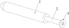
图1是导向件的结构示意图;Fig. 1 is the structural representation of the guide member;
图2是导向件插入套管后的示意图;Fig. 2 is the schematic diagram after the guide member is inserted into the sleeve;
图3是导向件和套管的正视图;Figure 3 is a front view of the guide and sleeve;
图4是图3的A-A剖视图;Fig. 4 is the A-A sectional view of Fig. 3;
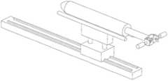
图5是导向件未完全插入套管时组合装置的示意图;Figure 5 is a schematic view of the assembly when the guide is not fully inserted into the casing;
图6是导向件完全插入套管时组合装置的示意图。Figure 6 is a schematic view of the assembly with the guide fully inserted into the cannula.
图中各附图标记为:The reference numbers in the figure are:
1、套管;2、尾管;3、导向件;4、导向部;5、弧形支撑部;6、夹持环;7、夹持限位机构;8、支撑辊组件;9、升降支撑机构;10、移动机构;11、夹持限位组件;12、限位板;13、活动板;14、第一伸缩元件;15、第一驱动元件;16、支撑辊;17、升降元件;18、支撑件;19、机座;20、滑轨;21、第一端;22、第一探测传感器;23、第二探测传感器;24、移动架。1. Casing; 2. Tail pipe; 3. Guide piece; 4. Guide part; 5. Arc support part; 6. Clamping ring; 7. Clamping limit mechanism; 8. Support roller assembly; 9. Lifting Supporting mechanism; 10. Moving mechanism; 11. Clamping limit assembly; 12. Limiting plate; 13. Active plate; 14. First telescopic element; 15. First driving element; 16. Support roller; 17. Lifting element ; 18, the support; 19, the machine base; 20, the slide rail; 21, the first end; 22, the first detection sensor; 23, the second detection sensor;
具体实施方式Detailed ways
下面结合各附图,对本发明做详细描述。The present invention will be described in detail below with reference to the accompanying drawings.
实施例1Example 1
如图1、2、3和4所示,一种预制棒的制造工艺,包括以下步骤:As shown in Figures 1, 2, 3 and 4, a manufacturing process of a preform includes the following steps:
(1)使导向件3插入熔接有尾管2的套管1上,导向件3包括位于尾管2内的导向部4以及位于套管1内的弧形支撑部5,且弧形支撑部5位于套管1内侧壁的最下方;(1) Insert the
(2)将设定数量的芯棒依次通过导向部4后插入套管1中,且最外端的芯棒通过玻璃棒顶入,各芯棒在弧形支撑部5上滑动,直至最里端的芯棒滑动至套管1底部;(2) Insert the set number of mandrels into the
(3)移除玻璃棒,将套管1转动设定角度,使芯棒不再压住弧形支撑部5;(3) Remove the glass rod, and rotate the
(4)将导向件3从套管1中移出;(4) Remove the
(5)重新插入玻璃棒,使玻璃棒顶住最外端的芯棒,得到预制棒。(5) Reinsert the glass rod so that the glass rod can withstand the outermost mandrel to obtain a preform.
本申请的制造工艺通过伸入套管1内的弧形支撑部5,能够有效防止芯棒与套管1之间直接接触摩擦,通过防止芯棒和套管1的划伤,有效保证了预制棒的质量;弧形支撑部5的设计,使得在芯棒插入后,通过转动设定角度使芯棒不再压住弧形支撑部5后,能够较为方便的将导向件3水平移出。The manufacturing process of the present application can effectively prevent the direct contact and friction between the mandrel and the
于本实施例中,设定角度为180°。转动180°后,使得弧形支撑部5位于芯棒的上方。In this embodiment, the set angle is 180°. After turning 180°, the arc-shaped
于本实施例中,导向部4为管状结构,导向件3的材质为特氟龙。In this embodiment, the
本实施例还公开了一种光纤,通过本实施例的制得的预制棒拉丝得到。This embodiment also discloses an optical fiber, which is obtained by drawing the preform obtained in this embodiment.
实施例2Example 2
如图5和6所示,本实施例公开了一种组合装置,可以用于实施实施例1的预制棒的制造工艺,组合装置包括:As shown in Figures 5 and 6, the present embodiment discloses a combined device, which can be used to implement the manufacturing process of the preform in Example 1. The combined device includes:
导向件3,具有依次设置的管状的导向部4以及弧形支撑部5,导向部4远离弧形支撑部5的一端具有夹持环6;The
夹持限位机构7,用于与导向件3的夹持环6配合,将导向件3夹紧限定住;The clamping and limiting
支撑辊组件8,用于支撑套管1并使套管1绕自身轴线转动;The support roller assembly 8 is used to support the
升降支撑机构9,用于支撑套管1并带动套管1上下移动,在套管1位于支撑辊组件8上方时,通过升降支撑机构9带动套管1下移,使套管1与支撑辊组件8配合;以及The lifting support mechanism 9 is used to support the
移动机构10,用于带动升降支撑机构9和套管1水平移动,使导向件3插入套管1内,且使套管1位于支撑辊组件8的上方。The moving
组合装置的一种工作方式:夹持限位机构7将导向件3水平夹紧,将熔接有尾管2的套管1放入升降支撑机构9上,通过移动机构10带动升降支撑机构9和套管1水平移动,使套管1移动至支撑辊组件8的上方,移动的同时,导向件3插入套管1内,使弧形支撑部5位于套管1内侧壁的最下方,导向部4位于尾管2内,夹持环6位于外管外部;通过人工或配套机械设备将设定数量的芯棒插入套管1,最外端的芯棒通过玻璃棒顶入,完成后,取出玻璃棒,夹持限位机构7不再夹持导向件3,升降支撑机构9带动套管1下移,使套管1与支撑辊组件8配合,支撑辊组件8带动套管1和导向件3转动设定角度(比如120°~180°),然后升降支撑机构9带动套管1上移,夹持限位机构7重新夹紧导向件3,移动机构10工作,带动套管1外移,从而导向件3能够从套管1内无压力的移出。A working mode of the combined device: the clamping and limiting
于本实施例中,夹持限位机构7包括分别设置在夹持环6左右两端的夹持限位组件11,夹持限位组件11包括:In this embodiment, the clamping and limiting
移动架24;mobile rack 24;
限位板12,固定在移动架24上;The limit plate 12 is fixed on the moving frame 24;
活动板13,滑动安装在移动架24上,与限位板12配合,用于夹紧夹持环6;The movable plate 13 is slidably installed on the movable frame 24 and cooperates with the limit plate 12 for clamping the
第一伸缩元件14,安装在移动架24上,用于驱动活动板13滑动;以及The first telescopic element 14, mounted on the moving frame 24, is used to drive the movable plate 13 to slide; and
第一驱动元件15,用于驱动移动架24接近夹持环6或远离夹持环6。The
通过第一伸缩元件14能够夹紧或释放夹持环6,通过第一驱动元件15能够带动移动架24移动,防止套管1和导向件3整体下移时与夹持限位组件11干涉。The first telescopic element 14 can clamp or release the
实际运用时,第一伸缩元件14可以为气缸、电动推杆等常规元器件,第一驱动元件15可以为气缸、电动推杆等常规元器件。In practice, the first telescopic element 14 may be a conventional component such as a cylinder and an electric push rod, and the
于本实施例中,支撑辊组件8包括两根平行设置的支撑辊16以及用于驱动至少一根支撑辊16转动的驱动电机(图中省略未画出)。In this embodiment, the support roller assembly 8 includes two
于本实施例中,升降支撑机构9包括升降元件17以及固定在升降元件17上的支撑件18,支撑件18的上表面为弧形,与套管1外表面相适配;In this embodiment, the lifting support mechanism 9 includes a lifting
移动机构10包括:The moving
机座19,机座19上具有滑轨20,升降元件17滑动安装在滑轨20上;以及The machine base 19, the machine base 19 is provided with a slide rail 20, and the lifting
水平驱动组件(图中省略未画出),用于驱动升降元件17沿滑轨20往复移动。The horizontal drive assembly (not shown in the figure) is used to drive the lifting
实际运用时,水平驱动组件可以采用现有的多种形式,比如丝杆副结构、齿轮齿条结构,传动带结构等。In practical application, the horizontal drive assembly can adopt various existing forms, such as a screw pair structure, a rack and pinion structure, a transmission belt structure, and the like.
于本实施例中,弧形支撑部5远离导向部4的一端为第一端21,弧形支撑部5的第一端21嵌装有第一探测传感器22,弧形支撑部5的弧形面靠近第一端21处嵌装有第二探测传感器23。In this embodiment, one end of the arc-shaped
通过第一探测传感器22能够探测导向件3是否插入到位,当第一探测传感器22探测到信号后,控制移动机构10停止移动,通过第二探测传感器23能够探测芯棒是否插入到位,当第二探测传感器23探测到信号后,不再对芯棒施加作用力。The
于本实施例中,第一探测传感器22为光电传感器或压力传感器,第二探测传感器23为光电传感器或压力传感器。In this embodiment, the
实施例3Example 3
本实施例与实施例2的区别在于,还包括与夹持限位组件配合的转动机构,该转动机构用于驱动夹持限位组件和导向件同步俯仰转动,因为导向件较长,长期使用后,弧形支撑部弯曲量变大,会影响套管正常的套入弧形支撑部的动作,通过设置转动机构能够使调节弧形支撑部的第一端的高度,从而能够确保套管与弧形支撑部接触的时候,能够一下子套入,且在套入后,转动机构复位,使导向件水平即可。The difference between this embodiment and
实际运用时,转动机构可以包括转动架以及驱动转动架转动的转动电机,夹持限位组件的第一驱动元件固定在转动架上。In practice, the rotating mechanism may include a turret and a rotating motor that drives the turret to rotate, and the first driving element of the clamping and limiting assembly is fixed on the turret.
以上所述仅为本发明的优选实施例,并非因此即限制本发明的专利保护范围,凡是运用本发明说明书及附图内容所作的等效结构变换,直接或间接运用在其他相关的技术领域,均同理包括在本发明的保护范围内。The above descriptions are only preferred embodiments of the present invention, and are not intended to limit the scope of patent protection of the present invention. Any equivalent structural transformation made by using the contents of the description and accompanying drawings of the present invention can be directly or indirectly used in other related technical fields. All are similarly included in the protection scope of the present invention.
Claims (10)
Translated fromChinesePriority Applications (1)
| Application Number | Priority Date | Filing Date | Title |
|---|---|---|---|
| CN202210172804.4ACN114634303A (en) | 2022-02-24 | 2022-02-24 | Preform manufacturing process and optical fiber |
Applications Claiming Priority (1)
| Application Number | Priority Date | Filing Date | Title |
|---|---|---|---|
| CN202210172804.4ACN114634303A (en) | 2022-02-24 | 2022-02-24 | Preform manufacturing process and optical fiber |
Publications (1)
| Publication Number | Publication Date |
|---|---|
| CN114634303Atrue CN114634303A (en) | 2022-06-17 |
Family
ID=81948393
Family Applications (1)
| Application Number | Title | Priority Date | Filing Date |
|---|---|---|---|
| CN202210172804.4APendingCN114634303A (en) | 2022-02-24 | 2022-02-24 | Preform manufacturing process and optical fiber |
Country Status (1)
| Country | Link |
|---|---|
| CN (1) | CN114634303A (en) |
Citations (10)
| Publication number | Priority date | Publication date | Assignee | Title |
|---|---|---|---|---|
| JP2001247324A (en)* | 2000-03-07 | 2001-09-11 | Shin Etsu Chem Co Ltd | Manufacturing method of preform for optical fiber and preform |
| US20060213228A1 (en)* | 2003-04-09 | 2006-09-28 | Heraeus Tenevo Gmbh | Method for the production of a blank mold for optical fibers |
| US20120179146A1 (en)* | 2011-01-06 | 2012-07-12 | Fan wei li | Cannulated guide tools |
| CN204342640U (en)* | 2014-12-22 | 2015-05-20 | 山东华鹏玻璃股份有限公司 | A kind of glass blows the once shaped mandrel of machine |
| CN106698918A (en)* | 2017-02-28 | 2017-05-24 | 长飞光纤光缆股份有限公司 | Sleeve-rod melting condensation holder |
| CN209442867U (en)* | 2018-09-21 | 2019-09-27 | 湖北新华光信息材料有限公司 | A kind of glass bar traction guiding device |
| CN110683753A (en)* | 2019-10-11 | 2020-01-14 | 华中科技大学 | Low-cost batch preparation method and system for multi-material multi-structure mid-infrared optical fiber |
| CN111060214A (en)* | 2019-12-24 | 2020-04-24 | 上海传输线研究所(中国电子科技集团公司第二十三研究所) | Fiber grating temperature measurement sensor and temperature measurement method of inner conductor of radio frequency cable |
| CN112239323A (en)* | 2020-10-23 | 2021-01-19 | 杭州富通通信技术股份有限公司 | Processing technology of prefabricated rod |
| CN114014531A (en)* | 2021-10-29 | 2022-02-08 | 浙江富通光纤技术有限公司 | Optical fiber preform manufacturing process and preform thereof |
- 2022
- 2022-02-24CNCN202210172804.4Apatent/CN114634303A/enactivePending
Patent Citations (10)
| Publication number | Priority date | Publication date | Assignee | Title |
|---|---|---|---|---|
| JP2001247324A (en)* | 2000-03-07 | 2001-09-11 | Shin Etsu Chem Co Ltd | Manufacturing method of preform for optical fiber and preform |
| US20060213228A1 (en)* | 2003-04-09 | 2006-09-28 | Heraeus Tenevo Gmbh | Method for the production of a blank mold for optical fibers |
| US20120179146A1 (en)* | 2011-01-06 | 2012-07-12 | Fan wei li | Cannulated guide tools |
| CN204342640U (en)* | 2014-12-22 | 2015-05-20 | 山东华鹏玻璃股份有限公司 | A kind of glass blows the once shaped mandrel of machine |
| CN106698918A (en)* | 2017-02-28 | 2017-05-24 | 长飞光纤光缆股份有限公司 | Sleeve-rod melting condensation holder |
| CN209442867U (en)* | 2018-09-21 | 2019-09-27 | 湖北新华光信息材料有限公司 | A kind of glass bar traction guiding device |
| CN110683753A (en)* | 2019-10-11 | 2020-01-14 | 华中科技大学 | Low-cost batch preparation method and system for multi-material multi-structure mid-infrared optical fiber |
| CN111060214A (en)* | 2019-12-24 | 2020-04-24 | 上海传输线研究所(中国电子科技集团公司第二十三研究所) | Fiber grating temperature measurement sensor and temperature measurement method of inner conductor of radio frequency cable |
| CN112239323A (en)* | 2020-10-23 | 2021-01-19 | 杭州富通通信技术股份有限公司 | Processing technology of prefabricated rod |
| CN114014531A (en)* | 2021-10-29 | 2022-02-08 | 浙江富通光纤技术有限公司 | Optical fiber preform manufacturing process and preform thereof |
Similar Documents
| Publication | Publication Date | Title |
|---|---|---|
| JP5674160B2 (en) | Drawing method of glass base material | |
| CN112239323B (en) | Processing technology of prefabricated rod | |
| CN112209615B (en) | Manufacturing method of optical fiber preform and optical fiber | |
| CN113526861B (en) | Automatic material taking and changing device for optical fiber preform | |
| CN114409242B (en) | Process for manufacturing optical fiber preform and optical fiber | |
| CN110815841B (en) | Pump core equipment | |
| CN109738992B (en) | Automatic threading machine | |
| CN215374809U (en) | Steel bar bending tester | |
| CN114014531B (en) | Manufacturing process of optical fiber preform and its preform | |
| CN116773356B (en) | A non-destructive testing device for round bars and round tubes of metal materials | |
| CN114634303A (en) | Preform manufacturing process and optical fiber | |
| CN119628345B (en) | Automatic wire plugging equipment | |
| CN118527846A (en) | An improved laser cutting machine | |
| CN115383608A (en) | Nonrust steel pipe inner wall polishing equipment | |
| CN115196869B (en) | Method for processing preform | |
| JP5147056B2 (en) | Method or apparatus for coil extraction and molding | |
| CN112060694B (en) | Paper bowl forming equipment | |
| CN113953341A (en) | Automatic pipe reducing machine with auxiliary feeding structure for pipe machining | |
| JP2011140412A (en) | Glass preform drawing apparatus and method for drawing glass preform | |
| CN116618900B (en) | Full-automatic welding equipment and welding method | |
| CN114180858B (en) | Prefabricated stick sleeve pipe pickling drying equipment | |
| JP2019089262A (en) | Mandrel extraction device | |
| CN214683681U (en) | Thin-wall pipe bending equipment | |
| CN223304497U (en) | Thin-wall gear heat treatment anti-deformation structure | |
| CN222843226U (en) | Pipe processing is with cutting segmentation machine |
Legal Events
| Date | Code | Title | Description |
|---|---|---|---|
| PB01 | Publication | ||
| PB01 | Publication | ||
| SE01 | Entry into force of request for substantive examination | ||
| SE01 | Entry into force of request for substantive examination | ||
| RJ01 | Rejection of invention patent application after publication | Application publication date:20220617 | |
| RJ01 | Rejection of invention patent application after publication |