CN114633824A - Biped robot and leg damping and energy recovery device thereof - Google Patents
Biped robot and leg damping and energy recovery device thereofDownload PDFInfo
- Publication number
- CN114633824A CN114633824ACN202210284177.3ACN202210284177ACN114633824ACN 114633824 ACN114633824 ACN 114633824ACN 202210284177 ACN202210284177 ACN 202210284177ACN 114633824 ACN114633824 ACN 114633824A
- Authority
- CN
- China
- Prior art keywords
- component
- coil
- energy recovery
- foot
- biped robot
- Prior art date
- Legal status (The legal status is an assumption and is not a legal conclusion. Google has not performed a legal analysis and makes no representation as to the accuracy of the status listed.)
- Pending
Links
- 238000011084recoveryMethods0.000titleclaimsabstractdescription41
- 238000013016dampingMethods0.000titleclaims6
- 230000005540biological transmissionEffects0.000claimsabstractdescription39
- 238000010521absorption reactionMethods0.000claimsabstractdescription19
- 210000000689upper legAnatomy0.000claimsdescription24
- 210000002414legAnatomy0.000claimsdescription18
- 210000000629knee jointAnatomy0.000claimsdescription16
- 210000004394hip jointAnatomy0.000claimsdescription10
- 238000000034methodMethods0.000claimsdescription7
- 230000002093peripheral effectEffects0.000claimsdescription3
- 238000009434installationMethods0.000claims1
- 230000000712assemblyEffects0.000abstractdescription30
- 238000000429assemblyMethods0.000abstractdescription30
- 230000035939shockEffects0.000abstractdescription16
- 230000006698inductionEffects0.000abstractdescription7
- 210000002683footAnatomy0.000description33
- 238000010586diagramMethods0.000description5
- 238000005265energy consumptionMethods0.000description4
- 230000033001locomotionEffects0.000description4
- 238000006243chemical reactionMethods0.000description2
- 230000005611electricityEffects0.000description2
- 210000000544articulatio talocruralisAnatomy0.000description1
- 230000009286beneficial effectEffects0.000description1
- 230000003139buffering effectEffects0.000description1
- 239000004020conductorSubstances0.000description1
- 230000000694effectsEffects0.000description1
- 238000004146energy storageMethods0.000description1
- 238000005516engineering processMethods0.000description1
- 210000001503jointAnatomy0.000description1
- 238000012986modificationMethods0.000description1
- 230000004048modificationEffects0.000description1
- 230000001360synchronised effectEffects0.000description1
Images


Classifications
- B—PERFORMING OPERATIONS; TRANSPORTING
- B62—LAND VEHICLES FOR TRAVELLING OTHERWISE THAN ON RAILS
- B62D—MOTOR VEHICLES; TRAILERS
- B62D57/00—Vehicles characterised by having other propulsion or other ground- engaging means than wheels or endless track, alone or in addition to wheels or endless track
- B62D57/02—Vehicles characterised by having other propulsion or other ground- engaging means than wheels or endless track, alone or in addition to wheels or endless track with ground-engaging propulsion means, e.g. walking members
- B62D57/032—Vehicles characterised by having other propulsion or other ground- engaging means than wheels or endless track, alone or in addition to wheels or endless track with ground-engaging propulsion means, e.g. walking members with alternately or sequentially lifted supporting base and legs; with alternately or sequentially lifted feet or skid
- H—ELECTRICITY
- H02—GENERATION; CONVERSION OR DISTRIBUTION OF ELECTRIC POWER
- H02N—ELECTRIC MACHINES NOT OTHERWISE PROVIDED FOR
- H02N2/00—Electric machines in general using piezoelectric effect, electrostriction or magnetostriction
- H02N2/18—Electric machines in general using piezoelectric effect, electrostriction or magnetostriction producing electrical output from mechanical input, e.g. generators
- H02N2/186—Vibration harvesters
Landscapes
- Engineering & Computer Science (AREA)
- Chemical & Material Sciences (AREA)
- Combustion & Propulsion (AREA)
- Transportation (AREA)
- Mechanical Engineering (AREA)
- Magnetic Treatment Devices (AREA)
Abstract
Translated fromChinese
Description
Translated fromChinese技术领域technical field
本发明属于机器人技术领域,特别是涉及一种双足机器人及其腿部减震和能量回收装置。The invention belongs to the technical field of robots, and in particular relates to a biped robot and its leg shock absorption and energy recovery device.
背景技术Background technique
目前,机器人的研究在世界各国都是一个创新的热点,尤其对拟人形态的双足机器人的研究更是如火如荼。At present, the research of robots is a hot spot of innovation in all countries in the world, especially the research on bipedal robots in anthropomorphic form is in full swing.
但是,现有技术中的双足机器人的腿部,采用的大都是三关节结构,脚部结构偏大,并通过踝关节缓震,控制难度较大,缓震效果不够理想;而且由于双足机器人实时驱动行走,能量损耗较高,严重制约了其续航、作业和负载能力。为此,我们提供了一种双足机器人及其腿部减震和能量回收装置,用以解决上述中的技术问题。However, most of the legs of the biped robots in the prior art adopt a three-joint structure, the foot structure is relatively large, and the ankle joint is used for cushioning, which is difficult to control, and the cushioning effect is not ideal; The robot drives walking in real time, and the energy consumption is high, which seriously restricts its endurance, operation and load capacity. To this end, we provide a biped robot and its leg shock absorption and energy recovery device to solve the above technical problems.
发明内容SUMMARY OF THE INVENTION
本发明的目的在于提供一种双足机器人及其腿部减震和能量回收装置,通过左右足部组件、磁线切割线圈、线圈驱转组件、传导组件和储电器的设计,解决了上述背景技术中的技术问题。The purpose of the present invention is to provide a biped robot and its leg shock absorption and energy recovery device, which solves the above background through the design of left and right foot components, magnetic wire cutting coils, coil driving components, conduction components and electrical storage devices. Technical issues in technology.
为解决上述技术问题,本发明是通过以下技术方案实现的:In order to solve the above-mentioned technical problems, the present invention is achieved through the following technical solutions:
本发明为一种双足机器人的腿部减震和能量回收装置,包括左右膝关节组件、左右股骨组件、左右大腿组件、髋关节组件和能量回收机构;所述左右膝关节组件连接于左右股骨组件底部,所述左右股骨组件连接于左右大腿组件底部,两所述左右大腿组件均连接于髋关节组件表面;所述能量回收机构包括左右足部组件、磁线切割线圈和线圈驱转组件,所述左右足部组件连接于左右膝关节组件底部;所述左右足部组件包括环形座,所述环形座相对两内侧面设置有能量回收磁铁,所述线圈驱转组件转动连接于环形座内底部,所述磁线切割线圈同轴心卡合在线圈驱转组件顶部,所述磁线切割线圈设置于两能量回收磁铁之间;所述左右足部组件还包括上下弹性移动的齿柱,所述齿柱上端贯穿环形座底部;所述齿柱表面啮合有传动结构,所述传动结构用于驱使线圈驱转组件旋转;所述磁线切割线圈顶部连接有传导组件,所述传导组件与髋关节组件表面的储电器通过导线电性连接。The invention relates to a leg shock absorption and energy recovery device for a biped robot, comprising left and right knee joint assemblies, left and right femur assemblies, left and right thigh assemblies, hip joint assemblies and energy recovery mechanism; the left and right knee joint assemblies are connected to the left and right femurs The bottom of the component, the left and right femur components are connected to the bottom of the left and right thigh components, and the two left and right thigh components are connected to the surface of the hip joint component; the energy recovery mechanism includes left and right foot components, magnetic wire cutting coils and coil drive components, The left and right foot assemblies are connected to the bottom of the left and right knee joint assemblies; the left and right foot assemblies include an annular seat, and energy recovery magnets are arranged on opposite inner sides of the annular seat, and the coil drive assembly is rotatably connected to the annular seat At the bottom, the magnetic wire cutting coil is coaxially clamped on the top of the coil driving assembly, and the magnetic wire cutting coil is arranged between two energy recovery magnets; The upper end of the tooth column penetrates the bottom of the annular seat; the surface of the tooth column is engaged with a transmission structure, and the transmission structure is used to drive the coil driving component to rotate; the top of the magnetic wire cutting coil is connected with a conductive component, and the conductive component is connected to the top of the magnetic wire cutting coil. The accumulator on the surface of the hip joint assembly is electrically connected by wires.
进一步地,所述左右足部组件还包括足板和固定座,所述固定座底部设置有空腔,所述空腔内顶部设置有减震弹性件,所述减震弹性件下端固定有移动台,所述移动台底部与足板顶部固定连接;所述固定座空腔内部设置有限位件,所述移动台底部紧密贴合于限位件顶部,用于限位足板上下运动的幅度;所述齿柱下端固定连接于移动台顶部。Further, the left and right foot assemblies further include a foot plate and a fixing seat, a cavity is arranged at the bottom of the fixing seat, a shock absorbing elastic member is arranged at the top of the cavity, and the lower end of the shock absorbing elastic member is fixed with a moving part. The bottom of the mobile platform is fixedly connected with the top of the foot plate; a limiting member is arranged inside the cavity of the fixed seat, and the bottom of the mobile platform is closely attached to the top of the limiting member to limit the amplitude of the up and down movement of the foot plate ; The lower end of the tooth column is fixedly connected to the top of the mobile platform.
进一步地,所述传动结构包括固定于环形座内底部的移动台,所述移动台表面通过转轴固定有第一传动齿轮,所述转轴周侧面固定有第二传动齿轮,所述第二传动齿轮与齿柱相啮合,通过第二传动齿轮带动齿柱进行上下运动。Further, the transmission structure includes a mobile platform fixed on the inner bottom of the annular seat, a first transmission gear is fixed on the surface of the mobile platform through a rotating shaft, a second transmission gear is fixed on the peripheral side of the rotating shaft, and the second transmission gear is fixed on the surface of the mobile platform. It meshes with the tooth column, and drives the tooth column to move up and down through the second transmission gear.
进一步地,所述线圈驱转组件包括转动连接于环形座内底部的支座,所述支座顶部通过连接杆固定有旋转环,所述旋转环外表面固定有同轴心的齿环,所述齿环与第一传动齿轮相啮合,在第二传动齿轮带动齿柱进行上下运动过程中,与第二传动齿轮同步旋转的第一传动齿轮带动齿环同步旋转,进而实现磁线切割线圈的旋转切割磁感线,将机器人行走时的震动能量转化为电能存储起来。Further, the coil driving assembly includes a support rotatably connected to the inner bottom of the annular seat, a rotating ring is fixed on the top of the support through a connecting rod, and a concentric toothed ring is fixed on the outer surface of the rotating ring, so The gear ring meshes with the first transmission gear, and in the process that the second transmission gear drives the tooth column to move up and down, the first transmission gear that rotates synchronously with the second transmission gear drives the gear ring to rotate synchronously, thereby realizing the magnetic wire cutting coil. The magnetic field lines are rotated and cut, and the vibration energy when the robot is walking is converted into electrical energy and stored.
进一步地,所述旋转环顶部对称设置有两线圈限位座,所述磁线切割线圈与两线圈限位座卡合连接。Further, two coil limit seats are symmetrically arranged on the top of the rotating ring, and the magnetic wire cutting coil is connected with the two coil limit seats by engaging.
进一步地,所述环形座顶部固定有第一足臂,所述第一足臂连接于左右膝关节组件底部;所述环形座底部与固定座顶部之间连接有第二足臂,所述第一足臂内部设置有L形安装孔,所述L形安装孔与环形座内部连通。Further, a first foot is fixed on the top of the annular seat, and the first foot is connected to the bottom of the left and right knee joint assemblies; a second foot is connected between the bottom of the annular seat and the top of the fixed seat, and the first foot is An L-shaped mounting hole is arranged inside a foot arm, and the L-shaped mounting hole communicates with the inside of the annular seat.
进一步地,所述传导组件包括L形传导件、第一导电头和第二导电头;所述L形传导件安装于L形安装孔内部,所述第一导电头转动连接于L形传导件下端部,所述第二导电头连接于L形传导件另一端部;所述第一导电头与磁线切割线圈顶部电性连接,所述第二导电头与储电器之间通过导线电性连接。Further, the conducting assembly includes an L-shaped conducting member, a first conducting head and a second conducting head; the L-shaped conducting member is installed inside the L-shaped mounting hole, and the first conducting head is rotatably connected to the L-shaped conducting member At the lower end, the second conductive head is connected to the other end of the L-shaped conductive member; the first conductive head is electrically connected to the top of the magnetic wire cutting coil, and the second conductive head is electrically connected to the electrical storage device through a wire connect.
进一步地,一种双足机器人,包括能量回收机构,该能量回收机构设置为上述任一项所述的双足机器人的腿部减震和能量回收装置。Further, a biped robot includes an energy recovery mechanism, and the energy recovery mechanism is configured as the leg shock absorption and energy recovery device of any one of the above-mentioned biped robots.
本发明具有以下有益效果:The present invention has the following beneficial effects:
1、本发明通过双足机器人的行走,利用减震弹性件能够实现机器人足部的减震,同时带动齿柱上下运动,在齿柱与第二传动齿轮以及第一传动齿轮与齿环的配合下,实现线圈驱转组件的正反向旋转,进行实现磁线切割线圈对磁感线的切割,有效实现双足机器人行走的震动能量转化为电能存储起来供机器人使用,从而降低了双足机器人的能耗,延长了双足机器人的续航和作业能力。1. In the present invention, through the walking of the biped robot, the shock absorption elastic parts can be used to realize the shock absorption of the robot feet, and at the same time drive the tooth column to move up and down. It realizes the forward and reverse rotation of the coil driving component, and realizes the cutting of the magnetic line of induction by the magnetic wire cutting coil, and effectively realizes that the vibration energy of the biped robot walking is converted into electrical energy and stored for the robot to use, thereby reducing the cost of the biped robot. The energy consumption of the biped robot extends the battery life and operation ability of the biped robot.
2、本发明通过将磁线切割线圈与第一导电头电性连接,第一导电头与L形传导件转动连接,在磁线切割线圈旋转切割磁感线的过程中,不会导致第二导电头处连接的导线的扭转,进而减少了切割磁感线过程中导线外皮的磨损,增加电流传输的安全性。2. In the present invention, the magnetic wire cutting coil is electrically connected with the first conductive head, and the first conductive head is rotatably connected with the L-shaped conductive member. During the process of the magnetic wire cutting coil rotating and cutting the magnetic induction line, the second The twisting of the wire connected at the conductive head reduces the wear of the wire sheath during cutting the magnetic field line, and increases the safety of current transmission.
附图说明Description of drawings
为了更清楚地说明本发明实施例的技术方案,下面将对实施例描述所需要使用的附图作简单地介绍,显而易见地,下面描述中的附图仅仅是本发明的一些实施例,对于本领域普通技术人员来讲,在不付出创造性劳动的前提下,还可以根据这些附图获得其他的附图。In order to illustrate the technical solutions of the embodiments of the present invention more clearly, the following briefly introduces the accompanying drawings used in the description of the embodiments. Obviously, the drawings in the following description are only some embodiments of the present invention. For those of ordinary skill in the art, other drawings can also be obtained from these drawings without any creative effort.
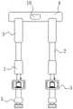
图1为一种双足机器人及其腿部减震和能量回收装置的结构示意图。FIG. 1 is a schematic structural diagram of a biped robot and its leg shock absorption and energy recovery device.
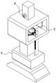
图2为能量回收机构的结构示意图。FIG. 2 is a schematic structural diagram of an energy recovery mechanism.
图3为图2的结构正视图。FIG. 3 is a front view of the structure of FIG. 2 .
图4为左右足部组件的结构示意图。FIG. 4 is a schematic structural diagram of left and right foot assemblies.
图5为图4中A处的局部结构放大图。FIG. 5 is an enlarged view of a part of the structure at A in FIG. 4 .
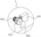
图6为图4一纵向结构剖视图。FIG. 6 is a cross-sectional view of a longitudinal structure of FIG. 4 .
图7为线圈驱转组件的结构示意图。FIG. 7 is a schematic structural diagram of the coil driving assembly.
图8为磁线切割线圈的结构示意图。FIG. 8 is a schematic view of the structure of the magnetic wire cutting coil.
图9为传导组件的结构示意图。FIG. 9 is a schematic diagram of the structure of the conduction component.
附图中,各标号所代表的部件列表如下:In the accompanying drawings, the list of components represented by each number is as follows:
1-左右膝关节组件,2-左右股骨组件,3-左右大腿组件,4-髋关节组件,5-能量回收机构,6-左右足部组件,601-环形座,602-能量回收磁铁,603-齿柱,604-足板,605-固定座,606-减震弹性件,607-移动台,608-耳座,609-第一传动齿轮,610-第二传动齿轮,611-第一足臂,612-第二足臂,613-L形安装孔,7-磁线切割线圈,8-线圈驱转组件,801-旋转环,802-齿环,803-线圈限位座,9-传导组件,901-L形传导件,902-第一导电头,903-第二导电头,10-储电器。1-Left and right knee joint components, 2-Left and right femur components, 3-Left and right thigh components, 4-Hip joint components, 5-Energy recovery mechanism, 6-Left and right foot components, 601-Ring seat, 602-Energy recovery magnet, 603 -Tooth column, 604-foot plate, 605-fixed seat, 606-shock-absorbing elastic element, 607-mobile table, 608-ear seat, 609-first transmission gear, 610-second transmission gear, 611-first foot Arm, 612-Second Foot Arm, 613-L-Shaped Mounting Hole, 7-Magnetic Wire Cutting Coil, 8-Coil Drive Assembly, 801-Rotating Ring, 802-Gear Ring, 803-Coil Limiting Seat, 9-Conducting Component, 901-L-shaped conductor, 902-first conductive head, 903-second conductive head, 10-electrical accumulator.
具体实施方式Detailed ways
下面将结合本发明实施例中的附图,对本发明实施例中的技术方案进行清楚、完整地描述,显然,所描述的实施例仅仅是本发明一部分实施例,而不是全部的实施例。基于本发明中的实施例,本领域普通技术人员在没有作出创造性劳动前提下所获得的所有其它实施例,都属于本发明保护的范围。The technical solutions in the embodiments of the present invention will be clearly and completely described below with reference to the accompanying drawings in the embodiments of the present invention. Obviously, the described embodiments are only a part of the embodiments of the present invention, but not all of the embodiments. Based on the embodiments of the present invention, all other embodiments obtained by those of ordinary skill in the art without creative efforts shall fall within the protection scope of the present invention.
请参阅图1-9,本发明为一种双足机器人的腿部减震和能量回收装置,包括左右膝关节组件1、左右股骨组件2、左右大腿组件3、髋关节组件4和能量回收机构5;其中,在左右大腿组件3内部分别设置有传动组件和驱动电机,且驱动电机位于髋关节组件4处;1-9, the present invention is a leg shock absorption and energy recovery device for a biped robot, including left and right knee joint assemblies 1, left and
左右膝关节组件1连接于左右股骨组件2底部,左右股骨组件2连接于左右大腿组件3底部,两左右大腿组件3均连接于髋关节组件4表面;能量回收机构5包括左右足部组件6、磁线切割线圈7和线圈驱转组件8,左右足部组件6连接于左右膝关节组件1底部;通过线圈驱转组件8带动磁线切割线圈7旋转,作切割磁感线运动发电,实现机器人的机械能向电能的转化;The left and right knee joint assemblies 1 are connected to the bottom of the left and
左右足部组件6包括环形座601,环形座601相对两内侧面设置有能量回收磁铁602,线圈驱转组件8转动连接于环形座601内底部,磁线切割线圈7同轴心卡合在线圈驱转组件8顶部,磁线切割线圈7设置于两能量回收磁铁602之间;通过磁线切割线圈7与线圈驱转组件8的配合作用,能够实现磁线切割线圈7与线圈驱转组件8的同步转动,进而使得磁线切割线圈7进行切割磁感线运动;The left and
左右足部组件6还包括上下弹性移动的齿柱603,齿柱603上端贯穿环形座601底部;齿柱603表面啮合有传动结构,传动结构用于驱使线圈驱转组件8旋转;The left and
磁线切割线圈7顶部连接有传导组件9,传导组件9与髋关节组件4表面的储电器10通过导线电性连接;通过双足机器人行走时的震动能量带动齿柱603上下运动,进而带动传动结构旋转,再利用传动结构带动线圈驱转组件8同步旋转,进而使得磁线切割线圈7进行切割磁感线运动发电,产生的电能通过储电器10获得储存。The top of the magnetic
本实施例中,左右足部组件6还包括足板604和固定座605,足板604作为双足机器人的踏板进行行走,固定座605底部设置有空腔,空腔内顶部设置有减震弹性件606,减震弹性件606下端固定有移动台607,移动台607底部与足板604顶部固定连接;在双足机器人行走过程中通过减震弹性件606对足板604起到很好的减震缓冲作用,从而实现双足机器人行走时的减震;In this embodiment, the left and
固定座605空腔内部设置有限位件,用于限位足板604上下运动的幅度,移动台607底部紧密贴合于限位件顶部;齿柱603下端固定连接于移动台607顶部。A limiting member is arranged inside the cavity of the fixed
本实施例中,传动结构包括固定于环形座601内底部的耳座608,耳座608表面通过转轴固定有第一传动齿轮609,转轴周侧面固定有第二传动齿轮610,第二传动齿轮610与齿柱603相啮合;In this embodiment, the transmission structure includes an
线圈驱转组件8包括转动连接于环形座601内底部的支座,支座顶部通过连接杆固定有旋转环801,旋转环801外表面固定有同轴心的齿环802,齿环802与第一传动齿轮609相啮合;通过双足机器人的行走,利用减震弹性件606能够实现机器人足部的减震,同时带动齿柱603上下运动,在齿柱603与第二传动齿轮610以及第一传动齿轮609与齿环802的配合下,实现线圈驱转组件8的正反向旋转,进行实现磁线切割线圈7对磁感线的切割,有效实现双足机器人行走的震动能量转化为电能存储起来供机器人使用,从而降低了双足机器人的能耗,延长了双足机器人的续航和作业能力。The
本实施例中,旋转环801顶部对称设置有两线圈限位座803,磁线切割线圈7与两线圈限位座803卡合连接,使得磁线切割线圈7随旋转环801同步旋转;环形座601顶部固定有第一足臂611,第一足臂611连接于左右膝关节组件1底部;环形座601底部与固定座605顶部之间连接有第二足臂612,第一足臂611内部设置有L形安装孔613,L形安装孔613与环形座601内部连通。In the present embodiment, two
本实施例中,传导组件9包括L形传导件901、第一导电头902和第二导电头903;L形传导件901安装于L形安装孔613内部,第一导电头902转动连接于L形传导件901下端部,第二导电头903连接于L形传导件901另一端部;In this embodiment, the
第一导电头902与磁线切割线圈7顶部电性连接,第二导电头903与储电器10之间通过导线电性连接;通过将磁线切割线圈7与第一导电头902电性连接,第一导电头902与L形传导件901转动连接,在磁线切割线圈7旋转切割磁感线的过程中,不会导致第二导电头903处连接的导线的扭转,进而减少了切割磁感线过程中导线外皮的磨损,增加电流传输的安全性。The first
本实施例中,一种双足机器人,包括能量回收机构5,该能量回收机构5设置为上述任一项双足机器人的腿部减震和能量回收装置,以提高双足机器人的稳定性,降低双足机器人的能耗。In this embodiment, a biped robot includes an
以上公开的本发明优选实施例只是用于帮助阐述本发明。优选实施例并没有详尽叙述所有的细节,也不限制该发明仅为所述的具体实施方式。显然,根据本说明书的内容,可作很多的修改和变化。本说明书选取并具体描述这些实施例,是为了更好地解释本发明的原理和实际应用,从而使所属技术领域技术人员能很好地理解和利用本发明。本发明仅受权利要求书及其全部范围和等效物的限制。The above-disclosed preferred embodiments of the present invention are provided only to help illustrate the present invention. The preferred embodiments do not exhaust all the details, nor do they limit the invention to only the described embodiments. Obviously, many modifications and variations are possible in light of the content of this specification. The present specification selects and specifically describes these embodiments in order to better explain the principles and practical applications of the present invention, so that those skilled in the art can well understand and utilize the present invention. The present invention is to be limited only by the claims and their full scope and equivalents.
Claims (9)
Priority Applications (1)
| Application Number | Priority Date | Filing Date | Title |
|---|---|---|---|
| CN202210284177.3ACN114633824A (en) | 2022-03-22 | 2022-03-22 | Biped robot and leg damping and energy recovery device thereof |
Applications Claiming Priority (1)
| Application Number | Priority Date | Filing Date | Title |
|---|---|---|---|
| CN202210284177.3ACN114633824A (en) | 2022-03-22 | 2022-03-22 | Biped robot and leg damping and energy recovery device thereof |
Publications (1)
| Publication Number | Publication Date |
|---|---|
| CN114633824Atrue CN114633824A (en) | 2022-06-17 |
Family
ID=81949840
Family Applications (1)
| Application Number | Title | Priority Date | Filing Date |
|---|---|---|---|
| CN202210284177.3APendingCN114633824A (en) | 2022-03-22 | 2022-03-22 | Biped robot and leg damping and energy recovery device thereof |
Country Status (1)
| Country | Link |
|---|---|
| CN (1) | CN114633824A (en) |
Citations (7)
| Publication number | Priority date | Publication date | Assignee | Title |
|---|---|---|---|---|
| CN105686930A (en)* | 2016-03-01 | 2016-06-22 | 芜湖安普机器人产业技术研究院有限公司 | Connecting rod and joint integrated hydraulic driving external skeleton |
| CN107672686A (en)* | 2017-09-20 | 2018-02-09 | 深圳市行者机器人技术有限公司 | A kind of biped robot and its leg damping and energy recycle device |
| CN108657305A (en)* | 2018-06-12 | 2018-10-16 | 中国地质大学(武汉) | The driving joint of robot of liquid metal pressure and self-generating device |
| US10226870B1 (en)* | 2014-11-11 | 2019-03-12 | Boston Dynamics, Inc. | Yaw slip handling in a robotic device |
| CN110576920A (en)* | 2019-08-06 | 2019-12-17 | 陇东学院 | A Lower Limb Mechanism of Hydraulic Biped Robot with Buffer Function |
| CN210555244U (en)* | 2019-10-16 | 2020-05-19 | 陇东学院 | An underactuated hydraulic biped robot lower limb mechanism |
| CN111846008A (en)* | 2020-07-30 | 2020-10-30 | 哈尔滨工业大学 | A bipedal robot with variable stiffness ankle joint |
- 2022
- 2022-03-22CNCN202210284177.3Apatent/CN114633824A/enactivePending
Patent Citations (7)
| Publication number | Priority date | Publication date | Assignee | Title |
|---|---|---|---|---|
| US10226870B1 (en)* | 2014-11-11 | 2019-03-12 | Boston Dynamics, Inc. | Yaw slip handling in a robotic device |
| CN105686930A (en)* | 2016-03-01 | 2016-06-22 | 芜湖安普机器人产业技术研究院有限公司 | Connecting rod and joint integrated hydraulic driving external skeleton |
| CN107672686A (en)* | 2017-09-20 | 2018-02-09 | 深圳市行者机器人技术有限公司 | A kind of biped robot and its leg damping and energy recycle device |
| CN108657305A (en)* | 2018-06-12 | 2018-10-16 | 中国地质大学(武汉) | The driving joint of robot of liquid metal pressure and self-generating device |
| CN110576920A (en)* | 2019-08-06 | 2019-12-17 | 陇东学院 | A Lower Limb Mechanism of Hydraulic Biped Robot with Buffer Function |
| CN210555244U (en)* | 2019-10-16 | 2020-05-19 | 陇东学院 | An underactuated hydraulic biped robot lower limb mechanism |
| CN111846008A (en)* | 2020-07-30 | 2020-10-30 | 哈尔滨工业大学 | A bipedal robot with variable stiffness ankle joint |
Similar Documents
| Publication | Publication Date | Title |
|---|---|---|
| CN201685709U (en) | Vibration type generating device | |
| CN211740539U (en) | Hydrogen fuel cell group vibrations test equipment | |
| CN205596001U (en) | Generator | |
| CN102078105A (en) | Electromagnetic power heartbeat simulation system serving as infant product | |
| CN114633824A (en) | Biped robot and leg damping and energy recovery device thereof | |
| CN103230176A (en) | Vehicle-mounted three-dimensional self-generating seat | |
| CN206167309U (en) | Spontaneous electromassage rocking chair of multi -functional end ratchet formula | |
| CN209364608U (en) | A Rigid-Flexible Switchable Elastic Actuator | |
| CN204553126U (en) | A kind of pedal power generating device for electric motor car emergent charging | |
| CN108644278B (en) | Shock absorption mechanism | |
| CN110539285A (en) | A Bionic Flexible Feet Tensioning Mechanism | |
| CN201105118Y (en) | Multifunctional pedal body-building cycle with reading platform | |
| CN107672686B (en) | A biped robot and its leg shock absorption and energy recovery device | |
| CN202930340U (en) | Modularized double-acting type high voltage circuit breaker | |
| CN107651036B (en) | A robot with adjustable chassis | |
| CN210413547U (en) | Fixing device is used in wheel arch production and processing | |
| CN200958465Y (en) | Vibration Generator with Shock Absorbing Function | |
| CN204378521U (en) | Screw mandrel pressure electricity-generating rocking chair | |
| CN201757040U (en) | Vibration power generation device | |
| CN210210660U (en) | Two-piece chassis welding device | |
| CN114291182A (en) | Light-duty high performance four-footed robot | |
| CN207694988U (en) | atmospheric ionization mode selector | |
| CN215647718U (en) | Electrical control cabinet | |
| CN211543147U (en) | Four-degree-of-freedom moving device | |
| CN221561337U (en) | Limb assist device for exoskeleton robot |
Legal Events
| Date | Code | Title | Description |
|---|---|---|---|
| PB01 | Publication | ||
| PB01 | Publication | ||
| SE01 | Entry into force of request for substantive examination | ||
| SE01 | Entry into force of request for substantive examination | ||
| WD01 | Invention patent application deemed withdrawn after publication | ||
| WD01 | Invention patent application deemed withdrawn after publication | Application publication date:20220617 |