CN114633736A - Method and device for determining limit bending speed of vehicle stable over bending - Google Patents
Method and device for determining limit bending speed of vehicle stable over bendingDownload PDFInfo
- Publication number
- CN114633736A CN114633736ACN202210179795.1ACN202210179795ACN114633736ACN 114633736 ACN114633736 ACN 114633736ACN 202210179795 ACN202210179795 ACN 202210179795ACN 114633736 ACN114633736 ACN 114633736A
- Authority
- CN
- China
- Prior art keywords
- vehicle
- speed
- phase plane
- road
- determining
- Prior art date
- Legal status (The legal status is an assumption and is not a legal conclusion. Google has not performed a legal analysis and makes no representation as to the accuracy of the status listed.)
- Granted
Links
- 238000000034methodMethods0.000titleclaimsabstractdescription45
- 238000005452bendingMethods0.000titleclaimsabstract8
- 238000011217control strategyMethods0.000claimsabstractdescription5
- 238000011156evaluationMethods0.000claimsdescription12
- 238000004590computer programMethods0.000claimsdescription10
- 239000011159matrix materialSubstances0.000claimsdescription8
- 230000000087stabilizing effectEffects0.000claims1
- 238000011160researchMethods0.000abstract1
- 230000006870functionEffects0.000description8
- 238000004088simulationMethods0.000description6
- 238000004458analytical methodMethods0.000description4
- 238000004364calculation methodMethods0.000description3
- 238000010586diagramMethods0.000description3
- 238000009795derivationMethods0.000description2
- 238000013461designMethods0.000description2
- 230000008569processEffects0.000description2
- 238000011158quantitative evaluationMethods0.000description2
- 229920006395saturated elastomerPolymers0.000description2
- 238000012360testing methodMethods0.000description2
- 230000001133accelerationEffects0.000description1
- 230000009286beneficial effectEffects0.000description1
- 238000012850discrimination methodMethods0.000description1
- 238000013210evaluation modelMethods0.000description1
- 238000002474experimental methodMethods0.000description1
- 238000011173large scale experimental methodMethods0.000description1
- 238000012986modificationMethods0.000description1
- 230000004048modificationEffects0.000description1
- 238000005096rolling processMethods0.000description1
- 238000006467substitution reactionMethods0.000description1
- 230000007704transitionEffects0.000description1
Images


Classifications
- B—PERFORMING OPERATIONS; TRANSPORTING
- B60—VEHICLES IN GENERAL
- B60W—CONJOINT CONTROL OF VEHICLE SUB-UNITS OF DIFFERENT TYPE OR DIFFERENT FUNCTION; CONTROL SYSTEMS SPECIALLY ADAPTED FOR HYBRID VEHICLES; ROAD VEHICLE DRIVE CONTROL SYSTEMS FOR PURPOSES NOT RELATED TO THE CONTROL OF A PARTICULAR SUB-UNIT
- B60W30/00—Purposes of road vehicle drive control systems not related to the control of a particular sub-unit, e.g. of systems using conjoint control of vehicle sub-units
- B60W30/02—Control of vehicle driving stability
- B60W30/04—Control of vehicle driving stability related to roll-over prevention
- B—PERFORMING OPERATIONS; TRANSPORTING
- B60—VEHICLES IN GENERAL
- B60W—CONJOINT CONTROL OF VEHICLE SUB-UNITS OF DIFFERENT TYPE OR DIFFERENT FUNCTION; CONTROL SYSTEMS SPECIALLY ADAPTED FOR HYBRID VEHICLES; ROAD VEHICLE DRIVE CONTROL SYSTEMS FOR PURPOSES NOT RELATED TO THE CONTROL OF A PARTICULAR SUB-UNIT
- B60W30/00—Purposes of road vehicle drive control systems not related to the control of a particular sub-unit, e.g. of systems using conjoint control of vehicle sub-units
- B60W30/10—Path keeping
- B60W30/12—Lane keeping
- B—PERFORMING OPERATIONS; TRANSPORTING
- B60—VEHICLES IN GENERAL
- B60W—CONJOINT CONTROL OF VEHICLE SUB-UNITS OF DIFFERENT TYPE OR DIFFERENT FUNCTION; CONTROL SYSTEMS SPECIALLY ADAPTED FOR HYBRID VEHICLES; ROAD VEHICLE DRIVE CONTROL SYSTEMS FOR PURPOSES NOT RELATED TO THE CONTROL OF A PARTICULAR SUB-UNIT
- B60W30/00—Purposes of road vehicle drive control systems not related to the control of a particular sub-unit, e.g. of systems using conjoint control of vehicle sub-units
- B60W30/14—Adaptive cruise control
- B60W30/143—Speed control
- B60W30/146—Speed limiting
- B—PERFORMING OPERATIONS; TRANSPORTING
- B60—VEHICLES IN GENERAL
- B60W—CONJOINT CONTROL OF VEHICLE SUB-UNITS OF DIFFERENT TYPE OR DIFFERENT FUNCTION; CONTROL SYSTEMS SPECIALLY ADAPTED FOR HYBRID VEHICLES; ROAD VEHICLE DRIVE CONTROL SYSTEMS FOR PURPOSES NOT RELATED TO THE CONTROL OF A PARTICULAR SUB-UNIT
- B60W30/00—Purposes of road vehicle drive control systems not related to the control of a particular sub-unit, e.g. of systems using conjoint control of vehicle sub-units
- B60W30/18—Propelling the vehicle
- B60W30/18009—Propelling the vehicle related to particular drive situations
- B60W30/18145—Cornering
- B—PERFORMING OPERATIONS; TRANSPORTING
- B60—VEHICLES IN GENERAL
- B60W—CONJOINT CONTROL OF VEHICLE SUB-UNITS OF DIFFERENT TYPE OR DIFFERENT FUNCTION; CONTROL SYSTEMS SPECIALLY ADAPTED FOR HYBRID VEHICLES; ROAD VEHICLE DRIVE CONTROL SYSTEMS FOR PURPOSES NOT RELATED TO THE CONTROL OF A PARTICULAR SUB-UNIT
- B60W30/00—Purposes of road vehicle drive control systems not related to the control of a particular sub-unit, e.g. of systems using conjoint control of vehicle sub-units
- B60W30/02—Control of vehicle driving stability
- B60W30/04—Control of vehicle driving stability related to roll-over prevention
- B60W2030/043—Control of vehicle driving stability related to roll-over prevention about the roll axis
- B—PERFORMING OPERATIONS; TRANSPORTING
- B60—VEHICLES IN GENERAL
- B60W—CONJOINT CONTROL OF VEHICLE SUB-UNITS OF DIFFERENT TYPE OR DIFFERENT FUNCTION; CONTROL SYSTEMS SPECIALLY ADAPTED FOR HYBRID VEHICLES; ROAD VEHICLE DRIVE CONTROL SYSTEMS FOR PURPOSES NOT RELATED TO THE CONTROL OF A PARTICULAR SUB-UNIT
- B60W2720/00—Output or target parameters relating to overall vehicle dynamics
- B60W2720/10—Longitudinal speed
- B—PERFORMING OPERATIONS; TRANSPORTING
- B60—VEHICLES IN GENERAL
- B60W—CONJOINT CONTROL OF VEHICLE SUB-UNITS OF DIFFERENT TYPE OR DIFFERENT FUNCTION; CONTROL SYSTEMS SPECIALLY ADAPTED FOR HYBRID VEHICLES; ROAD VEHICLE DRIVE CONTROL SYSTEMS FOR PURPOSES NOT RELATED TO THE CONTROL OF A PARTICULAR SUB-UNIT
- B60W2720/00—Output or target parameters relating to overall vehicle dynamics
- B60W2720/24—Direction of travel
Landscapes
- Engineering & Computer Science (AREA)
- Automation & Control Theory (AREA)
- Transportation (AREA)
- Mechanical Engineering (AREA)
- Control Of Driving Devices And Active Controlling Of Vehicle (AREA)
- Steering Control In Accordance With Driving Conditions (AREA)
Abstract
Description
Translated fromChinese技术领域technical field
本发明涉及汽车控制领域,特别是涉及一种控制下车辆稳定过弯的极限入弯速度的确定方法及装置。The invention relates to the field of automobile control, in particular to a method and a device for determining the limit entry speed of a vehicle under control for stable cornering.
背景技术Background technique
极限速度指车辆在不偏离道路且不发生侧翻的情况下可以正常通过预设场景的最高速度。实际场景中,极限速度往往很难通过实验获取,这是因为极限速度时,车辆往往运行在极限工况中,极易发生危险。同时,在实际场景中进行大规模工况的实验是费时费力的事情。The limit speed refers to the maximum speed at which the vehicle can normally pass through the preset scene without deviating from the road and rolling over. In actual scenarios, it is often difficult to obtain the limit speed through experiments, because at the limit speed, the vehicle often runs in the limit working condition, which is very prone to danger. At the same time, it is time-consuming and laborious to conduct large-scale experiments in actual scenarios.
极限速度的判断涉及车身和轨迹两方面稳定性。目前常用的车身稳定性判定方法主要有分岔理论、李雅普诺夫函数和相平面方法。分岔理论和李雅普诺夫函数依赖于车辆模型的公式推导和数学求解,在高维度的车辆模型中,需要通过复杂的数学运算估算鞍点(分岔理论法)或者确定函数形式(李雅普诺夫函数法)。相平面方法不依赖数学求解,可以通过仿真的方法确定稳定边界对车辆的稳定性进行分析,易于向高自由度模型拓展,但目前的方法往往仅限于单一相平面中(单独考虑质心侧偏角-横摆角速度相平面或前轮滑移角-后轮滑移角相平面),而在车辆非线性动力学的情况下,车辆在不同相平面中的稳定性存在不一致性,使用单一相平面难以综合考虑车辆多维度的稳定情况。The judgment of the limit speed involves the stability of both the body and the trajectory. At present, the commonly used methods for judging vehicle body stability mainly include bifurcation theory, Lyapunov function and phase plane method. Bifurcation theory and Lyapunov function rely on the formula derivation and mathematical solution of the vehicle model. In high-dimensional vehicle models, it is necessary to estimate the saddle point (bifurcation theory method) or determine the functional form (Lyapunov function) through complex mathematical operations. Law). The phase plane method does not rely on mathematical solutions, and the stability boundary can be determined by the simulation method to analyze the stability of the vehicle, which is easy to expand to the high-degree-of-freedom model, but the current method is often limited to a single phase plane (considering the center of mass slip angle alone). - yaw rate phase plane or front wheel slip angle - rear wheel slip angle phase plane), while in the case of non-linear vehicle dynamics where there is inconsistency in vehicle stability in different phase planes, a single phase plane is used It is difficult to comprehensively consider the multi-dimensional stability of the vehicle.
发明内容SUMMARY OF THE INVENTION
基于背景所述方法以及不足,本发明的主要目的是提供一种车辆稳定过弯的极限入弯速度的确定方法,其能够结合仿真给出LQR控制下车辆不偏离道路边界且车身不发生失稳的极限入弯速度。Based on the methods and shortcomings of the background, the main purpose of the present invention is to provide a method for determining the limit entry speed of the vehicle in stable cornering, which can combine the simulation to show that the vehicle does not deviate from the road boundary and the vehicle body does not become unstable under LQR control. limit entry speed.
本发明的技术问题通过以下的技术方案予以解决:The technical problem of the present invention is solved by the following technical solutions:
一种车辆稳定过弯的极限入弯速度的确定方法,包括如下步骤:A method for determining the limit entry speed for a vehicle to stably turn a corner, comprising the following steps:
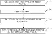
S1-1:构建二自由度非线性车辆动力学模型对相平面空间进行生成;S1-1: Build a two-degree-of-freedom nonlinear vehicle dynamics model to generate the phase plane space;
S1-2:构建相平面空间数据库;S1-2: Build a phase plane space database;
S1-3:设计闭环控制策略应用于车辆动力学仿真软件的轨迹跟踪控制;S1-3: Design a closed-loop control strategy for trajectory tracking control of vehicle dynamics simulation software;
S1-4:找到车辆不偏离道路及车身稳定情况下通过场景的最大速度,此即车辆稳定过弯的极限入弯速度。S1-4: Find the maximum speed of the vehicle passing through the scene when the vehicle does not deviate from the road and the body is stable, which is the limit entry speed for the vehicle to stably corner.
优选地,步骤S1-1中,通过建模车辆的横摆特性和轮胎特性,得到质心侧偏角、横摆角速度、前轮滑移角、后轮滑移角的积分关系。Preferably, in step S1-1, by modeling the yaw characteristics and tire characteristics of the vehicle, the integral relationship of the center of mass slip angle, yaw rate, front wheel slip angle, and rear wheel slip angle is obtained.
优选地,步骤S1-2中包括如下步骤:Preferably, step S1-2 includes the following steps:
S1-2-1、通过相平面中轨迹的发散和收敛特性,定义流线型的稳定边界;S1-2-1, through the divergence and convergence characteristics of the trajectory in the phase plane, define the stable boundary of the streamline;
S1-2-2、对速度、路面附着系数、前轮转向角进行一定范围和精度的遍历,构建相平面空间数据库。S1-2-2, traverse the speed, road adhesion coefficient, and front wheel steering angle to a certain range and accuracy, and build a phase plane space database.
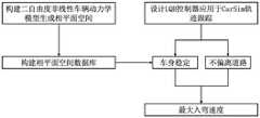
优选地,步骤S1-3包括:设计LQR控制器,应用于CarSim的轨迹跟踪控制。Preferably, step S1-3 includes: designing an LQR controller, which is applied to the trajectory tracking control of CarSim.
优选地,步骤S1-3包括:Preferably, step S1-3 includes:
S1-3-1、构建弯道道路场景;S1-3-1, construct a curved road scene;
S1-3-2、基于线性二自由度动力学模型构建LQR控制器,得到最优的状态反馈矩阵;S1-3-2, build an LQR controller based on a linear two-degree-of-freedom dynamic model to obtain the optimal state feedback matrix;
S1-3-3、进而得到最优转向角输入量。S1-3-3, and then obtain the optimal steering angle input.
优选地,步骤S1-4中包括:逐渐增加LQR控制下CarSim的入弯速度,找到车辆不偏离道路及车身稳定情况下通过场景的极限速度。Preferably, step S1-4 includes: gradually increasing the cornering speed of CarSim under LQR control, and finding the limit speed of the vehicle passing through the scene when the vehicle does not deviate from the road and the vehicle body is stable.
优选地,步骤S1-4包括:Preferably, step S1-4 includes:
S1-4-1、将CarSim输出的车辆位置坐标与弯道道路模型中道路边界坐标序列进行比对得出车辆是否偏离道路;S1-4-1. Compare the vehicle position coordinates output by CarSim with the road boundary coordinate sequence in the curved road model to obtain whether the vehicle deviates from the road;
S1-4-2、进行车辆车身稳定性评价;S1-4-2, evaluate the stability of the vehicle body;
S1-4-3、利用格点搜索法对极限入弯速度进行搜索,确定车辆稳定过弯的极限入弯速度。S1-4-3. Use the grid point search method to search the limit entry speed to determine the limit entry speed for the vehicle to stably pass the corner.
优选地,步骤S1-4-2包括:Preferably, step S1-4-2 includes:
S1-4-2-1、利用CarSim输出的速度、前轮转向角,道路模型中的路面附着系数在相平面空间数据库中搜索,并得到对应工况下相平面空间的稳定边界;S1-4-2-1. Use the speed output by CarSim, the steering angle of the front wheel, and the road surface adhesion coefficient in the road model to search in the phase plane space database, and obtain the stable boundary of the phase plane space under the corresponding working conditions;
S1-4-2-2、利用相平面空间数据库中的速度邻域确定该相平面空间的稳定边界的范围,划分相平面空间稳定区域;S1-4-2-2. Use the velocity neighborhood in the phase plane space database to determine the range of the stable boundary of the phase plane space, and divide the phase plane space stable region;
S1-4-2-3、利用车辆状态点与相平面稳定区域边界的相对位置和最短距离对车辆稳定性定量化评价;S1-4-2-3. Use the relative position and shortest distance between the vehicle state point and the boundary of the phase plane stability area to quantitatively evaluate the vehicle stability;
S1-4-2-4、利用相平面的包络面面积对单张相平面中的稳定性结果进行加权,得到相平面空间中车辆稳定性的综合评价结果。S1-4-2-4. Use the envelope surface area of the phase plane to weight the stability results in the single phase plane to obtain a comprehensive evaluation result of vehicle stability in the phase plane space.
一种计算机可读介质,其存储有计算机程序,所述计算机程序可被计算机读取并执行以实现所述的方法。A computer-readable medium storing a computer program that can be read and executed by a computer to implement the method.
一种车辆稳定过弯的极限入弯速度的确定装置,包括处理器和存储器,所述存储器中存储有计算机程序,所述计算机程序可被处理器读取并执行以实现所述的方法。A device for determining the limit entry speed of a vehicle stably turning a corner includes a processor and a memory, wherein the memory stores a computer program, and the computer program can be read and executed by the processor to implement the method.
与现有技术相比,本发明具有如下的有益的效果:Compared with the prior art, the present invention has the following beneficial effects:
本发明的车辆稳定过弯的极限入弯速度的确定方法是基于仿真域的虚拟测试方法,其可以解决实际道路测试中代价大、测试周期长、危险性高的问题,通过仿真,可以测试车辆在所有可能速度下通过场景的情况,以此确定该场景下车辆的极限入弯速度。其中,在车身稳定性评价方面,将单一相平面中的稳定性分析扩展至在相平面空间中进行稳定性分析,避免了由于非线性程度高而导致的单一相平面稳定性评价不一致性的问题。The method for determining the limit entry speed of the vehicle for stable cornering of the present invention is a virtual test method based on the simulation domain, which can solve the problems of high cost, long test cycle and high risk in actual road tests. Through simulation, the vehicle can be tested Pass the scene at all possible speeds to determine the vehicle's limit entry speed in the scene. Among them, in the stability evaluation of the vehicle body, the stability analysis in a single phase plane is extended to the stability analysis in the phase plane space, which avoids the problem of inconsistency in the stability evaluation of a single phase plane caused by the high degree of nonlinearity. .
附图说明Description of drawings
图1是本发明车辆稳定过弯的极限入弯速度的确定方法的流程图;Fig. 1 is the flow chart of the method for determining the limit entry speed for stable cornering of the vehicle according to the present invention;
图2是本发明LQR控制下车辆稳定过弯的极限入弯速度快速确定方法的具体化流程图;Fig. 2 is the specific flow chart of the method for quickly determining the limit entry speed for stable cornering of the vehicle under the LQR control of the present invention;
图3是本发明生成相平面空间使用的二自由度非线性车辆动力学模型的示意图;3 is a schematic diagram of the two-degree-of-freedom nonlinear vehicle dynamics model used in the generation of the phase plane space according to the present invention;
图4是本发明LQR控制使用的考虑道路约束的线性二自由度动力学模型的示意图;4 is a schematic diagram of a linear two-degree-of-freedom dynamic model considering road constraints used in LQR control of the present invention;
图5是利用相平面空间进行车辆稳定性评价的流程图。FIG. 5 is a flow chart of vehicle stability evaluation using phase plane space.
具体实施方式Detailed ways
下面对照附图并结合优选的实施方式对本发明作进一步说明。需要说明的是,在不冲突的情况下,本申请中的实施例及实施例中的特征可以相互组合。The present invention will be further described below with reference to the accompanying drawings and in conjunction with the preferred embodiments. It should be noted that the embodiments in the present application and the features of the embodiments may be combined with each other in the case of no conflict.
需要说明的是,本实施例中的左、右、上、下、顶、底等方位用语,仅是互为相对概念,或是以产品的正常使用状态为参考的,而不应该认为是具有限制性的。It should be noted that the azimuth terms such as left, right, top, bottom, top and bottom in this embodiment are only relative concepts to each other, or refer to the normal use state of the product, and should not be considered as having restrictive.
下面结合具体实施例对本发明进行详细说明。以下实施例将有助于本领域的技术人员进一步理解本发明,但不以任何形式限制本发明。应当指出的是,对本领域的普通技术人员来说,在不脱离本发明构思的前提下,还可以做出若干变化和改进。这些都属于本发明的保护范围。The present invention will be described in detail below with reference to specific embodiments. The following examples will help those skilled in the art to further understand the present invention, but do not limit the present invention in any form. It should be noted that, for those skilled in the art, several changes and improvements can be made without departing from the inventive concept. These all belong to the protection scope of the present invention.
极限工况下车辆非线性程度高,使用单一相平面进行车身稳定性评价容易出现在某一相平面稳定,而另一相平面不稳定的情况。针对此,本发明将单一相平面中的稳定性评价扩展至在相平面空间中进行稳定性评价,避免了由于非线性程度高而导致的单一相平面稳定性评价不一致性的问题,获得了一致的评价结果。The vehicle has a high degree of nonlinearity under extreme working conditions, and it is easy to use a single phase plane to evaluate the vehicle body stability in a situation where one phase plane is stable and the other phase plane is unstable. In view of this, the present invention extends the stability evaluation in the single phase plane to the stability evaluation in the phase plane space, which avoids the problem of inconsistency in the stability evaluation of the single phase plane caused by the high degree of nonlinearity, and achieves consistent results. evaluation results.
如图1-5所示,本发明实施例提供了一种车辆稳定过弯的极限入弯速度的确定方法,具体步骤如下:As shown in Figures 1-5, an embodiment of the present invention provides a method for determining the limit entry speed of a vehicle for stable cornering, and the specific steps are as follows:
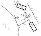
步骤一:构建二自由度非线性车辆动力学模型对相平面空间进行生成。较优的是,在步骤一中,通过建模车辆的横摆特性和轮胎特性,得到质心侧偏角、横摆角速度、前轮滑移角、后轮滑移角的积分关系式生成质心侧偏角-横摆角速度、前轮滑移角-后轮滑移角、质心侧偏角-质心侧偏角速度三类相平面构成相平面空间。具体地,车辆的轮胎特性使用Fiala轮胎模型,整车动力学模型(即二自由度非线性车辆动力学模型)重点考虑车辆的横摆建模。Step 1: Build a two-degree-of-freedom nonlinear vehicle dynamics model to generate the phase plane space. Preferably, in
其中,二自由度非线性车辆动力学模型如图3所示,模型主要度量车辆的横摆特性,具体为:Among them, the two-degree-of-freedom nonlinear vehicle dynamics model is shown in Figure 3. The model mainly measures the yaw characteristics of the vehicle, specifically:


其中

轮胎的侧向受力Fy和侧偏角α的关系由Fiala轮胎模型给出,具体为:The relationship between the lateral force Fy of the tire and the slip angle α is given by the Fiala tire model, specifically:

其中Cα表示车辆轮胎的侧偏刚度;α表示车辆轮胎的侧偏角;μ表示路面附着系数;Fz表示车辆轮胎的垂直受力。αsl表示轮胎饱和时的轮胎侧偏角。where Cα represents the cornering stiffness of the vehicle tire; α represents the cornering angle of the vehicle tire; μ represents the road adhesion coefficient; Fz represents the vertical force of the vehicle tire. αsl represents the tire slip angle when the tire is saturated.
轮胎饱和时的轮胎侧偏角由以下公式给出:The tire slip angle when the tire is saturated is given by:

前轮的垂直载荷Fzf和后轮的垂直载荷Fzr分别由以下公式给出:The vertical load Fzf of the front wheel and the vertical load Fzr of the rear wheel are respectively given by the following equations:


前轮侧偏角αf和后轮的侧偏角αr分别由以下公式给出:The front wheel slip angle αf and the rear wheel slip angle αr are respectively given by the following equations:


其中,δ为前轮转角,β为车辆的质心侧偏角。Among them, δ is the front wheel turning angle, and β is the vehicle's center of mass slip angle.
步骤一利用二自由度非线性车辆动力学模型对质心侧偏角-横摆角速度(β-r)、前轮滑移角-后轮滑移角(αf-αr)、质心侧偏角-质心侧偏角速度


步骤二:构建相平面空间数据库。Step 2: Build the phase plane space database.
具体过程如下:The specific process is as follows:
步骤201:通过相平面中轨迹的发散和收敛特性,仿真得到流线型的稳定边界。相平面中的轨迹为不同初始值下的参数时序序列,其中Vi选择最外侧的两条收敛轨迹作为稳定边界。也即,在该步骤201中,找到最外侧的收敛曲线,直接利用相平面中的轨迹作为稳定边界(轨迹是通过积分迭代得到的,生成方法和其他方法(如李雅普诺夫方法等)一致,而稳定边界则通过对每条曲线收敛性判断得到)。通过该步骤201,稳定性分析中的稳定边界利用数值方法给出,回避了公式推导和数学求解(例如李雅普诺夫方法需要推导公式找到李雅普诺夫函数再确定稳定边界,分岔理论需要推导公式并用牛顿解析法估计鞍节点位置再确定稳定边界),易于向高自由度车辆模型进行扩展。Step 201: A streamlined stable boundary is obtained by simulation through the divergence and convergence characteristics of the trajectory in the phase plane. The trajectories in the phase plane are the time series of parameters under different initial values, whereVi selects the two outermost convergent trajectories as stable boundaries. That is, in this step 201, the outermost convergence curve is found, and the trajectory in the phase plane is directly used as the stable boundary (the trajectory is obtained by integral iteration, and the generation method is consistent with other methods (such as the Lyapunov method, etc.), The stability boundary is obtained by judging the convergence of each curve). Through this step 201, the stability boundary in the stability analysis is given by numerical method, which avoids formula derivation and mathematical solution (for example, the Lyapunov method needs to derive the formula to find the Lyapunov function and then determine the stability boundary, and the bifurcation theory needs to derive the formula And use the Newton analytical method to estimate the position of the saddle node and then determine the stability boundary), which is easy to expand to the high-degree-of-freedom vehicle model.
步骤202:对速度、路面附着系数、前轮转向角进行一定范围和精度的遍历,构建相平面空间数据库。具体来说,通过速度、前轮转向角和路面附着系数遍历获得覆盖全工况的相平面空间数据库,例如,可以根据实际工况中速度、路面附着系数和前轮转向角的变化范围,和期望的精度要求对范围和步长进行自由选择。本发明中,意图覆盖从常规工况到极限工况的情况,速度使用0.5m/s-50m/s,步长0.5m/s;路面附着系数使用0.1-0.9,步长0.1;前轮转向角-10deg-50deg,步长0.5deg。在相平面空间数据库中,速度、路面附着系数、前轮转向角作为索引,储存索引组合下由步骤201得到的相平面空间稳定边界(即流线型的稳定边界)。Step 202 : traverse the speed, road adhesion coefficient, and steering angle of the front wheel to a certain range and accuracy, and construct a phase plane space database. Specifically, a phase-plane space database covering all operating conditions is obtained by traversing the speed, the steering angle of the front wheels and the road adhesion coefficient. The desired accuracy requires free choice of range and step size. In the present invention, it is intended to cover the situation from normal working conditions to extreme working conditions, the speed is 0.5m/s-50m/s, the step size is 0.5m/s; the road adhesion coefficient is 0.1-0.9, the step size is 0.1; front wheel steering Angle-10deg-50deg, step size 0.5deg. In the phase plane space database, the speed, road adhesion coefficient, and front wheel steering angle are used as indexes, and the phase plane space stability boundary (ie, the streamlined stability boundary) obtained in step 201 under the index combination is stored.
步骤三:设计闭环控制策略应用于车辆动力学仿真软件的轨迹跟踪控制。较优的是,基于CarSim设计LQR(linearquadraticregulator,线性二次型调节器)控制器应用于车辆的轨迹跟踪控制(即设计LQR控制器,应用于CarSim的轨迹跟踪控制)。Step 3: Design a closed-loop control strategy and apply it to the trajectory tracking control of vehicle dynamics simulation software. Preferably, an LQR (linear quadratic regulator, linear quadratic regulator) controller is designed based on CarSim and applied to the trajectory tracking control of the vehicle (ie, the LQR controller is designed and applied to the trajectory tracking control of CarSim).
具体为:Specifically:
步骤301:构建弯道道路场景(即图5中的“道路模型”)。使用(x,y)坐标序列表达道路边界。路面附着系数输入CarSim模型(即图5中的“车辆模型”)。Step 301: Construct a curved road scene (ie, the "road model" in Fig. 5). Road boundaries are expressed using a sequence of (x,y) coordinates. The road adhesion coefficient is input into the CarSim model (ie "Vehicle Model" in Figure 5).
步骤302:构建LQR控制器。具体地,基于线性二自由度动力学模型构建LQR控制器,得到最优的状态反馈矩阵K=(k1 k2 k3 k4),进而得到最优转向角输入量。Step 302: Build an LQR controller. Specifically, an LQR controller is constructed based on a linear two-degree-of-freedom dynamic model, and the optimal state feedback matrix K=(k1 k2 k3 k4 ) is obtained, and then the optimal steering angle input is obtained.
其中,线性二自由度动力学模型示意图如图4所示,加入负反馈控制的状态转移矩阵简记如下:The schematic diagram of the linear two-degree-of-freedom dynamic model is shown in Figure 4, and the state transition matrix with negative feedback control is abbreviated as follows:

最优前轮转角控制量由下式给出:The optimal front wheel steering angle control amount is given by:

其中


定义如下目标函数:Define the following objective function:

其中Q为状态权重系数,R为控制权重系数,k标记状态序列序号。针对道路跟随误差及航向误差对控制量的影响,权重矩阵Q选取如下式:Where Q is the state weight coefficient, R is the control weight coefficient, and k marks the state sequence number. In view of the influence of road following error and heading error on the control quantity, the weight matrix Q is selected as follows:

输入控制量为前轮转向角,权重矩阵R退化为常系数,设值R为1。The input control variable is the steering angle of the front wheel, the weight matrix R is degenerated into a constant coefficient, and the value R is set to 1.
目标函数J最小时,得到最优的状态反馈矩阵K,由下式给出:When the objective function J is the smallest, the optimal state feedback matrix K is obtained, which is given by the following formula:
K=(R+BTPB)-1BTPAK=(R+BT PB)-1 BT PA
其中矩阵P满足里卡蒂方程where the matrix P satisfies the Riccati equation
P=ATPA-ATPB(R+BTPB)-1BTPA+QP=AT PA-AT PB(R+BT PB)-1 BT PA+Q
可以使用matlab中lqr函数进行求解,得到当前车辆状态下最优的前轮转向角控制量。The lqr function in matlab can be used to solve the problem to obtain the optimal front wheel steering angle control amount under the current vehicle state.
步骤四:仿真域中搜索极限入弯速度,即格点搜索法搜索车辆不偏离道路及车身稳定情况下通过场景的最大速度,此即车辆稳定过弯的极限入弯速度。具体包括:逐渐增加LQR控制下CarSim的入弯速度,通过格点搜索法从大粒度向小粒度对速度搜索,得到车辆不偏离道路及车身稳定情况下通过场景的最大速度。Step 4: Search for the limit entry speed in the simulation domain, that is, the grid search method searches for the maximum speed of the vehicle passing through the scene without deviating from the road and the vehicle body is stable, which is the limit entry speed of the vehicle stably cornering. Specifically, it includes: gradually increasing the cornering speed of CarSim under LQR control, and searching for the speed from large granularity to small granularity by grid search method to obtain the maximum speed of the vehicle passing through the scene when the vehicle does not deviate from the road and the body is stable.
具体为:Specifically:
步骤401:将CarSim输出的车辆位置坐标与弯道道路模型(即图5中的“道路模型”)中道路边界坐标序列进行比对得出车辆是否偏离道路。Step 401 : Compare the vehicle position coordinates output by CarSim with the road boundary coordinate sequence in the curved road model (ie, the “road model” in FIG. 5 ) to obtain whether the vehicle deviates from the road.
步骤402:进行车辆车身稳定性评价。其具体流程如图5所示,包括:Step 402: Evaluate the stability of the vehicle body. The specific process is shown in Figure 5, including:
步骤402-1:通过车辆状态及道路模型在相平面空间数据库中检索对应工况下相平面空间的稳定边界,具体来说,是利用CarSim输出的速度、前轮转向角,道路模型中的路面附着系数在步骤二中构建的相平面空间数据库中搜索,并得到对应工况下相平面空间的稳定边界。步骤402-2:利用相平面空间数据库中的速度邻域确定该相平面空间的稳定边界的范围,划分相平面空间稳定区域。在稳定边界附近,车辆的非线性较强,二自由度非线性模型存在一定误差。这种误差是不可避免的,导致步骤201中定义的稳定边界不够准确,因而利用速度邻域设计一段模糊区域作为临界稳定区域。速度邻域指在相平面空间数据库中,与指定相平面空间相隔一速度步长的两张相平面空间,将两张相平面空间稳定边界间的区域定义为临界稳定区域,实现稳定边界的扩展,得到更加保守的稳定区域。Step 402-1: Retrieve the stable boundary of the phase plane space under the corresponding working conditions in the phase plane space database through the vehicle state and the road model. The adhesion coefficient is searched in the phase plane space database constructed in step 2, and the stable boundary of the phase plane space under the corresponding working conditions is obtained. Step 402-2: Determine the range of the stable boundary of the phase plane space by using the velocity neighborhood in the phase plane space database, and divide the phase plane space stable region. Near the stability boundary, the nonlinearity of the vehicle is strong, and there is a certain error in the two-degree-of-freedom nonlinear model. This error is unavoidable, resulting in the inaccuracy of the stability boundary defined in step 201. Therefore, a fuzzy region is designed by using the velocity neighborhood as a critical stable region. Velocity neighborhood refers to two phase plane spaces in the phase plane space database that are separated from the specified phase plane space by one velocity step. The area between the two phase plane space stable boundaries is defined as a critical stable area to realize the expansion of the stable boundary. , to obtain a more conserved stable region.
步骤402-3:利用车辆状态点与相平面稳定区域边界的相对位置和最短距离对车辆稳定性定量化评价。车辆状态参数:质心侧偏角、横摆角速度、前轮滑移角、后轮滑移角、质心侧偏角角速度分别对应质心侧偏角-横摆角速度相平面、前轮滑移角-后轮滑移角相平面、质心侧偏角-质心侧偏角速度相平面中的一个状态点。当状态点位于相平面稳定区域内部,该相平面中车辆状态评价为稳定;当状态点位于相平面临界稳定区域和不稳定区域内部,该相平面中车辆状态评价为不稳定。计算状态点与稳定区域边界的最短距离,作为该时刻车辆状态在该相平面中的稳定性定量化评价结果,对不稳定状态,定量化评价结果取最短距离的相反数(负值)。Step 402-3: Quantitatively evaluate the vehicle stability by using the relative position and the shortest distance between the vehicle state point and the boundary of the phase plane stability region. Vehicle state parameters: center of mass slip angle, yaw angular velocity, front wheel slip angle, rear wheel slip angle, and center of mass slip angle angular velocity respectively correspond to the phase plane of mass center slip angle-yaw angular velocity, front wheel slip angle-rear wheel slip angle A state point in the phase plane of wheel slip angle, centroid slip angle - centroid slip angle velocity phase plane. When the state point is located in the stable region of the phase plane, the vehicle state in the phase plane is evaluated as stable; when the state point is located in the critical stable region and the unstable region of the phase plane, the vehicle state in the phase plane is evaluated as unstable. The shortest distance between the state point and the boundary of the stable region is calculated as the quantitative evaluation result of the stability of the vehicle state in the phase plane at this moment. For the unstable state, the quantitative evaluation result takes the opposite number (negative value) of the shortest distance.
步骤402-4:利用相平面的包络面面积对单张相平面中的稳定性结果进行加权,得到相平面空间中车辆稳定性的综合评价结果,即利用归一化加权的方法,将不同相平面中可能存在的不一致结果进行了统一,获得了一致的评价结果。评价结果的正和负分别对应状态的稳定和不稳定。Step 402-4: Use the envelope surface area of the phase plane to weight the stability results in the single phase plane to obtain a comprehensive evaluation result of the vehicle stability in the phase plane space, that is, use the normalized weighting method to calculate the different stability results. The possible inconsistent results in the phase plane were unified, and a consistent evaluation result was obtained. The positive and negative evaluation results correspond to the stable and unstable states, respectively.
步骤403:利用格点搜索法对极限入弯速度进行搜索。具体地,先以较大粒度逐渐增加车辆入弯速度,通过步骤401和402的判别方法找到车辆发生失稳的速度区间;在区间内以较小粒度调整车辆入弯速度,确定车辆稳定过弯的极限速度。。Step 403: Search the limit entry speed by using the grid point search method. Specifically, first gradually increase the vehicle's cornering speed with a larger granularity, and find the speed range where the vehicle is unstable through the discrimination methods in steps 401 and 402; adjust the vehicle's cornering speed with a smaller granularity within the range to determine that the vehicle is stably cornering limit speed. .
步骤四通过对LQR控制下车辆入弯速度的遍历,利用稳定性定量化评价模型及道路约束对车辆行驶中参数序列进行综合评价,得到LQR控制下车辆稳定过弯的最大入弯速度Step 4: Through the traversal of the vehicle's cornering speed under LQR control, the quantitative stability evaluation model and road constraints are used to comprehensively evaluate the parameter sequence of the vehicle during driving, and the maximum cornering speed of the vehicle under LQR control is obtained.
本发明实施例还提供一种计算机可读介质,其存储有计算机程序,所述计算机程序可被计算机读取并执行以实现上述实施例所述的车辆稳定过弯的极限入弯速度的确定方法。Embodiments of the present invention further provide a computer-readable medium, which stores a computer program, and the computer program can be read and executed by a computer to realize the method for determining the limit entry speed of a vehicle for stable cornering according to the above embodiments .
本发明实施例还提供一种车辆稳定过弯的极限入弯速度的确定装置,其包括处理器和存储器,所述存储器中存储有计算机程序,所述计算机程序可被处理器读取并执行以实现上述实施例所述的车辆稳定过弯的极限入弯速度的确定方法。Embodiments of the present invention also provide a device for determining a limit entry speed for a vehicle to stably turn a corner, which includes a processor and a memory, where a computer program is stored in the memory, and the computer program can be read and executed by the processor to The method for determining the limit entry speed for the stable cornering of the vehicle described in the above embodiments is realized.
以上实施例是针对LQR控制进行的车辆稳定过弯的临界速度确定,在其他变型示例中,还可以设计其他闭环控制策略,例如针对PID(Proportional Integral Derivative)控制。The above embodiment is aimed at determining the critical speed for stable cornering of the vehicle by LQR control. In other modified examples, other closed-loop control strategies can also be designed, such as PID (Proportional Integral Derivative) control.
以上内容是结合具体的优选实施方式对本发明所作的进一步详细说明,不能认定本发明的具体实施只局限于这些说明。对于本发明所属技术领域的技术人员来说,在不脱离本发明构思的前提下,还可以做出若干等同替代或明显变型,而且性能或用途相同,都应当视为属于本发明的保护范围。The above content is a further detailed description of the present invention in combination with specific preferred embodiments, and it cannot be considered that the specific implementation of the present invention is limited to these descriptions. For those skilled in the art to which the present invention belongs, under the premise of not departing from the concept of the present invention, several equivalent substitutions or obvious modifications can be made, and the performance or use is the same, which should be regarded as belonging to the protection scope of the present invention.
Claims (10)
Priority Applications (1)
| Application Number | Priority Date | Filing Date | Title |
|---|---|---|---|
| CN202210179795.1ACN114633736B (en) | 2022-02-25 | 2022-02-25 | A method and device for determining a vehicle's stable cornering speed limit |
Applications Claiming Priority (1)
| Application Number | Priority Date | Filing Date | Title |
|---|---|---|---|
| CN202210179795.1ACN114633736B (en) | 2022-02-25 | 2022-02-25 | A method and device for determining a vehicle's stable cornering speed limit |
Publications (2)
| Publication Number | Publication Date |
|---|---|
| CN114633736Atrue CN114633736A (en) | 2022-06-17 |
| CN114633736B CN114633736B (en) | 2024-12-31 |
Family
ID=81948621
Family Applications (1)
| Application Number | Title | Priority Date | Filing Date |
|---|---|---|---|
| CN202210179795.1AActiveCN114633736B (en) | 2022-02-25 | 2022-02-25 | A method and device for determining a vehicle's stable cornering speed limit |
Country Status (1)
| Country | Link |
|---|---|
| CN (1) | CN114633736B (en) |
Citations (7)
| Publication number | Priority date | Publication date | Assignee | Title |
|---|---|---|---|---|
| DE102016215287A1 (en)* | 2016-08-16 | 2018-02-22 | Volkswagen Aktiengesellschaft | Method for determining a maximum possible driving speed for cornering a motor vehicle, control device and motor vehicle |
| CN108674414A (en)* | 2018-07-02 | 2018-10-19 | 清华大学 | A kind of intelligent automobile Trajectory Tracking Control method of limiting condition |
| CN109808679A (en)* | 2017-11-17 | 2019-05-28 | 郑州宇通客车股份有限公司 | A kind of bend method for controlling driving speed, bend vehicle speed control system |
| CN109976159A (en)* | 2019-04-09 | 2019-07-05 | 台州学院 | Intelligent vehicle crosswise joint method based on safely controllable domain |
| CN109969183A (en)* | 2019-04-09 | 2019-07-05 | 台州学院 | Curve following control method based on safety controllable domain |
| CN111572558A (en)* | 2020-04-01 | 2020-08-25 | 北京理工大学 | A Dynamic Control Method for Maximum Envelope of Unmanned Vehicles |
| CN113111514A (en)* | 2021-04-12 | 2021-07-13 | 清华大学深圳国际研究生院 | Vehicle microscopic driving scene simulation method and computer readable storage medium |
- 2022
- 2022-02-25CNCN202210179795.1Apatent/CN114633736B/enactiveActive
Patent Citations (7)
| Publication number | Priority date | Publication date | Assignee | Title |
|---|---|---|---|---|
| DE102016215287A1 (en)* | 2016-08-16 | 2018-02-22 | Volkswagen Aktiengesellschaft | Method for determining a maximum possible driving speed for cornering a motor vehicle, control device and motor vehicle |
| CN109808679A (en)* | 2017-11-17 | 2019-05-28 | 郑州宇通客车股份有限公司 | A kind of bend method for controlling driving speed, bend vehicle speed control system |
| CN108674414A (en)* | 2018-07-02 | 2018-10-19 | 清华大学 | A kind of intelligent automobile Trajectory Tracking Control method of limiting condition |
| CN109976159A (en)* | 2019-04-09 | 2019-07-05 | 台州学院 | Intelligent vehicle crosswise joint method based on safely controllable domain |
| CN109969183A (en)* | 2019-04-09 | 2019-07-05 | 台州学院 | Curve following control method based on safety controllable domain |
| CN111572558A (en)* | 2020-04-01 | 2020-08-25 | 北京理工大学 | A Dynamic Control Method for Maximum Envelope of Unmanned Vehicles |
| CN113111514A (en)* | 2021-04-12 | 2021-07-13 | 清华大学深圳国际研究生院 | Vehicle microscopic driving scene simulation method and computer readable storage medium |
Also Published As
| Publication number | Publication date |
|---|---|
| CN114633736B (en) | 2024-12-31 |
Similar Documents
| Publication | Publication Date | Title |
|---|---|---|
| CN112092815B (en) | Vehicle track changing tracking control method based on model prediction | |
| Dal Bianco et al. | Comparison of direct and indirect methods for minimum lap time optimal control problems | |
| CN108569336B (en) | Steering control method based on vehicle kinematics model under dynamic constraints | |
| Bertolazzi et al. | Symbolic–numeric indirect method for solving optimal control problems for large multibody systems: the time-optimal racing vehicle example | |
| CN105867377A (en) | A method for automatic navigation control of agricultural machinery | |
| Qin et al. | Nonholonomic dynamics and control of road vehicles: moving toward automation | |
| Saccon et al. | A virtual rider for motorcycles: Maneuver regulation of a multi-body vehicle model | |
| CN113467470B (en) | Trajectory tracking control method of unmanned autonomous trolley | |
| CN116811864B (en) | Large-curvature curve bending planning and control method for automatic driving vehicle | |
| Gu et al. | Genetic algorithm based LQR control for AGV path tracking problem | |
| CN115407656B (en) | Intelligent agricultural machinery autonomous operation control method and system based on dynamic adaptive LQR | |
| Amdouni et al. | Optimal control approach developed to four-wheel active steering vehicles | |
| Fényes et al. | LPV-based autonomous vehicle control using the results of big data analysis on lateral dynamics | |
| CN116184835A (en) | Unmanned vehicle tracking control method considering input time delay and speed time variation | |
| CN115167424A (en) | Path tracking control method of intelligent agricultural machine | |
| Hill et al. | Online gain setting method for path tracking using CMA-ES: Application to off-road mobile robot control | |
| Saccon et al. | A virtual rider for motorcycles: An approach based on optimal control and maneuver regulation | |
| CN114633736A (en) | Method and device for determining limit bending speed of vehicle stable over bending | |
| Talj et al. | Immersion and invariance control for lateral dynamics of autonomous vehicles, with experimental validation | |
| CN116841298B (en) | Finite time tracking control method suitable for four-wheel mobile robot lane change early warning | |
| Oh et al. | LQR-based adaptive steering control algorithm of multi-axle crane for improving driver's steering efficiency and dynamic stability | |
| Wang et al. | Research on path tracking control of unmanned vehicle | |
| CN117113626A (en) | Data-driven vehicle body stability judging method | |
| CN116795102A (en) | Linear path tracking anti-interference control method and control system for wheeled agricultural machinery | |
| CN104636591A (en) | Nonlinear analysis method for steering stability of electric automobile |
Legal Events
| Date | Code | Title | Description |
|---|---|---|---|
| PB01 | Publication | ||
| PB01 | Publication | ||
| SE01 | Entry into force of request for substantive examination | ||
| SE01 | Entry into force of request for substantive examination | ||
| GR01 | Patent grant | ||
| GR01 | Patent grant |