CN114633102A - A slewing bearing assembly system based on industrial robots - Google Patents
A slewing bearing assembly system based on industrial robotsDownload PDFInfo
- Publication number
- CN114633102A CN114633102ACN202210452471.0ACN202210452471ACN114633102ACN 114633102 ACN114633102 ACN 114633102ACN 202210452471 ACN202210452471 ACN 202210452471ACN 114633102 ACN114633102 ACN 114633102A
- Authority
- CN
- China
- Prior art keywords
- sleeve
- tightening
- slewing bearing
- bolt
- robot
- Prior art date
- Legal status (The legal status is an assumption and is not a legal conclusion. Google has not performed a legal analysis and makes no representation as to the accuracy of the status listed.)
- Withdrawn
Links
- 230000000007visual effectEffects0.000claimsdescription17
- 238000000034methodMethods0.000claimsdescription8
- 238000001514detection methodMethods0.000claimsdescription6
- 230000001681protective effectEffects0.000claimsdescription4
- 230000003044adaptive effectEffects0.000claims1
- 238000010586diagramMethods0.000description5
- 230000000694effectsEffects0.000description2
- 238000004519manufacturing processMethods0.000description2
- 238000005452bendingMethods0.000description1
- 230000009286beneficial effectEffects0.000description1
- 230000008094contradictory effectEffects0.000description1
Images


Classifications
- B—PERFORMING OPERATIONS; TRANSPORTING
- B23—MACHINE TOOLS; METAL-WORKING NOT OTHERWISE PROVIDED FOR
- B23P—METAL-WORKING NOT OTHERWISE PROVIDED FOR; COMBINED OPERATIONS; UNIVERSAL MACHINE TOOLS
- B23P19/00—Machines for simply fitting together or separating metal parts or objects, or metal and non-metal parts, whether or not involving some deformation; Tools or devices therefor so far as not provided for in other classes
- B23P19/04—Machines for simply fitting together or separating metal parts or objects, or metal and non-metal parts, whether or not involving some deformation; Tools or devices therefor so far as not provided for in other classes for assembling or disassembling parts
- B23P19/06—Screw or nut setting or loosening machines
- B—PERFORMING OPERATIONS; TRANSPORTING
- B23—MACHINE TOOLS; METAL-WORKING NOT OTHERWISE PROVIDED FOR
- B23P—METAL-WORKING NOT OTHERWISE PROVIDED FOR; COMBINED OPERATIONS; UNIVERSAL MACHINE TOOLS
- B23P19/00—Machines for simply fitting together or separating metal parts or objects, or metal and non-metal parts, whether or not involving some deformation; Tools or devices therefor so far as not provided for in other classes
Landscapes
- Engineering & Computer Science (AREA)
- Mechanical Engineering (AREA)
- Automatic Assembly (AREA)
Abstract
Description
Translated fromChinese技术领域technical field
本申请涉及智能化装配技术领域,特别涉及一种基于工业机器人的回转支承装配系统。The present application relates to the technical field of intelligent assembly, in particular to a slewing bearing assembly system based on an industrial robot.
背景技术Background technique
智能化装配是大型机械行业的发展方向。相对于其它行业,大型机械行业实现智能化装配有其特殊性,需装配的零件尺寸和重量大,制造精度相对较低,对智能化装配设备提出了挑战,给实现带来了较大困难。因而长期以来该行业继续沿用以往落后的装配模式,以手动和以助力机械辅助的人工装配为主,制约了产能和装配质量的提高,也无法实现更高程度的数字化装配和管理。Intelligent assembly is the development direction of the large machinery industry. Compared with other industries, the realization of intelligent assembly in the large-scale machinery industry has its particularity. The size and weight of the parts to be assembled are large, and the manufacturing accuracy is relatively low, which poses challenges to intelligent assembly equipment and brings great difficulties to the realization. Therefore, for a long time, the industry continued to use the backward assembly mode, mainly manual assembly and manual assembly assisted by power-assisted machinery, which restricted the improvement of production capacity and assembly quality, and could not achieve a higher degree of digital assembly and management.
为适应智能化高效率的发展要求,大型机械产品装配领域近年来加大在智能化装配设备领域的投资,希望通过采用智能装配设备改变大型机械装配以手工装配为主,速度慢,效率低,近乎原始的装配方式。其中典型的装配回转支承时遇到需拧紧螺栓多,不便观察,耗时长的问题。In order to meet the development requirements of intelligent and high-efficiency, the field of large-scale mechanical product assembly has increased investment in the field of intelligent assembly equipment in recent years. Near-original assembly. Among them, the typical assembly of the slewing bearing encounters the problem that many bolts need to be tightened, which is inconvenient to observe and takes a long time.
在现有技术中,回转支承装配主要采用人工方式进行作业,操作工在作业的过程中使用悬挂式拧紧枪,通过弯腰目视及人手摸索来实现拧紧枪头与螺栓的对位。In the prior art, the assembly of the slewing bearing is mainly performed manually. The operator uses a hanging tightening gun during the operation, and realizes the alignment of the tightening gun head and the bolt by bending over visually and manually groping.
但是由于螺栓头的位置处于下方而不便观察,进而导致螺栓需要通过多次移动拧紧枪才能对准,且在回转支承的作业中需要拧紧的螺栓较多,拧紧所有螺栓费时较长,进而严重影响到回转支承装配的效率,有待改进。However, because the position of the bolt head is in the lower position, it is inconvenient to observe, and the bolt needs to move the tightening gun several times to be aligned. In addition, many bolts need to be tightened during the operation of the slewing bearing, and it takes a long time to tighten all the bolts, which seriously affects the The efficiency of slewing bearing assembly needs to be improved.
发明内容SUMMARY OF THE INVENTION
有鉴于此,本申请的目的在于提供一种基于工业机器人的回转支承装配系统,以实现显著提升装配效率和质量的目的。其具体方案如下:In view of this, the purpose of the present application is to provide a slewing bearing assembly system based on an industrial robot, so as to achieve the purpose of significantly improving assembly efficiency and quality. Its specific plan is as follows:
一种基于工业机器人的回转支承装配系统,包括相互匹配的套筒更换部和机器人拧紧部;A slewing bearing assembly system based on an industrial robot, comprising a sleeve replacement part and a robot tightening part that match each other;
所述套筒更换部用于供所述机器人拧紧部替换套筒;The sleeve replacement part is used to replace the sleeve for the robot tightening part;
所述机器人拧紧部由机器人底座、固定在所述机器人底座上端的机器人本体和由所述机器人本体驱动移动的拧紧机构组成;The robot tightening part is composed of a robot base, a robot body fixed on the upper end of the robot base, and a tightening mechanism driven and moved by the robot body;
所述拧紧机构用于确定回转支承的中心和基准点位置,并获取待拧紧螺栓的中心位置和驱动套筒将螺栓头部拧紧至设定扭矩。The tightening mechanism is used to determine the center of the slewing bearing and the position of the reference point, obtain the center position of the bolt to be tightened, and the driving sleeve to tighten the bolt head to the set torque.
优选地:还包括包围所述套筒更换部和机器人拧紧部的安全围栏和用于运载回转支承和零件的轨道车,所述安全围栏的开口处设置有激光光幕,所述激光光幕用于在人员或异物进入所述安全围栏内时发出警报。Preferably: it also includes a safety fence surrounding the sleeve replacement part and the robot tightening part and a rail car for carrying the slewing bearing and parts, a laser light curtain is arranged at the opening of the safety fence, and the laser light curtain is used for An alarm is issued when a person or foreign object enters the safety fence.
优选地:所述套筒更换部包括套筒支架以及固定在所述套筒支架上的套筒活动叉、套筒检测部和套筒定位部;所述套筒定位部用于与所述拧紧机构垂直匹配,以回收和替换不同规格和型号的套筒;所述套筒检测部用于检测所述拧紧机构与套筒定位部的定位匹配;所述套筒活动叉由气缸驱动运行,并用于插入套筒中心O型槽连接固定。Preferably: the sleeve replacement part includes a sleeve support, a sleeve movable fork fixed on the sleeve support, a sleeve detection part and a sleeve positioning part; the sleeve positioning part is used for tightening with the sleeve The mechanism is vertically matched to recover and replace the sleeves of different specifications and models; the sleeve detection part is used to detect the positioning matching of the tightening mechanism and the sleeve positioning part; the sleeve movable fork is driven by the cylinder and runs with It is connected and fixed with the O-shaped groove in the center of the inserted sleeve.
优选地:所述拧紧部包括安装座、拧紧部、测量部和视觉定位部;所述拧紧部和测量部分别固定在所述安装座的两端,且所述拧紧部用于拧紧螺栓,所述测量部用于测量螺栓;所述视觉定位部位于所述安装座的底部,并用于确定回转支承的中心和基准点位置。Preferably: the tightening part includes a mounting seat, a tightening part, a measuring part and a visual positioning part; the tightening part and the measuring part are respectively fixed on both ends of the mounting seat, and the tightening part is used for tightening the bolt, so The measuring part is used for measuring bolts; the visual positioning part is located at the bottom of the mounting seat, and is used to determine the center of the slewing bearing and the position of the reference point.
优选地:所述安装座包括安装支架和反力支架,所述安装座用于提供安装平台,并与所述机器人本体连接,所述反力支架用于在拧紧作业时卸载扭力。Preferably, the mounting seat includes a mounting bracket and a reaction force bracket, the mounting seat is used for providing a mounting platform and connected with the robot body, and the reaction force bracket is used for unloading the torque during the tightening operation.
优选地:所述拧紧部包括滑动导向A柱、滑动导向B柱、拧紧枪和枪头配套套筒;所述拧紧枪为电动高精度拧紧枪,并用于固定套筒和驱动套筒拧紧螺栓;所述滑动导向B柱套接有弹簧,并用于在拧紧螺栓时将所述拧紧枪上的套筒压紧在螺栓头部上以补偿螺栓头部拧紧过程中的移动。Preferably: the tightening part includes a sliding guide A column, a sliding guide B column, a tightening gun and a matching sleeve for the gun head; the tightening gun is an electric high-precision tightening gun, and is used for fixing the sleeve and driving the sleeve to tighten the bolts; The sliding guide B column is sleeved with a spring, and is used to press the sleeve on the tightening gun against the bolt head when the bolt is tightened to compensate for the movement of the bolt head during the tightening process.
优选地:所述测量部包括保护罩和高精度测量仪,所述测量仪用于扫描初步固定在回转支承上的螺栓头部的垫圈外缘并获取螺栓中心位置。Preferably, the measuring part includes a protective cover and a high-precision measuring instrument, and the measuring instrument is used to scan the outer edge of the washer of the head of the bolt preliminarily fixed on the slewing bearing and obtain the center position of the bolt.
优选地:所述视觉定位部由工业相机和视觉控制器组成,所述工业相机用于对回转支承和基准点拍照以获得位置照片,并将照片传送至视觉控制器,所述视觉控制器用于计算获取准确坐标,并将准确坐标传送至所述测量部。Preferably: the visual positioning part is composed of an industrial camera and a vision controller, the industrial camera is used to take pictures of the slewing bearing and the reference point to obtain a position picture, and transmit the picture to the vision controller, and the vision controller is used for Accurate coordinates are obtained by calculation, and the accurate coordinates are transmitted to the measuring part.
优选地:所述套筒更换部与所述机器人拧紧部均设置有两个并对称分布在回转支承行进方向的两侧。Preferably, the sleeve replacement part and the robot tightening part are provided with two and symmetrically distributed on both sides of the slewing bearing in the traveling direction.
优选地:所述机器人拧紧部的运行包括如下步骤:Preferably: the operation of the robot tightening part includes the following steps:
步骤1、视觉定位部对回转支承拍照并确定回转支承的中心和基准点位置;
步骤2、测量部扫描螺栓并确定螺栓的中心位置,若套筒与螺栓匹配,则继续步骤3,否则继续步骤4;
步骤3、机器人本体驱动机器人拧紧部,令机器人拧紧部驱动套筒套入回转支承上的螺栓头部内并拧紧螺栓至设定扭矩,再拧紧半圈;
步骤4、测量部扫描确认回转支承上螺栓拧紧状态,若已完成全部螺栓拧紧作业,则停止运行,否则继续步骤2;
步骤5、机器人本体驱动拧紧部移动至套筒更换部替换适配套筒,并继续步骤2。Step 5. The robot body drives the tightening part to move to the sleeve replacement part to replace the adapter sleeve, and proceeds to
通过以上方案可知,本申请提供了一种基于工业机器人的回转支承装配系统,该基于工业机器人的回转支承装配系统具有以下有益效果:It can be seen from the above solutions that the present application provides a slewing bearing assembly system based on an industrial robot, and the slewing bearing assembly system based on an industrial robot has the following beneficial effects:
1、通过安全围栏包围套筒更换部、机器人拧紧部和轨道车,并在安全围栏的开口处设置有激光光幕,并通过警报的方式以在该基于工业机器人的回转支承装配系统作业时防止有人员或异物进入安全围栏内而发生意外;1. The sleeve replacement part, the robot tightening part and the rail car are surrounded by a safety fence, and a laser light curtain is set at the opening of the safety fence, and an alarm is used to prevent the industrial robot-based slewing bearing assembly system from operating. An accident occurs when a person or foreign object enters the safety fence;
2、通过机器人本体驱动拧紧部移动到拧紧枪与套筒定位部同轴在其下方一定距离处,再垂直向上移动,直到套筒进入套筒定位部后,通过气缸带动套筒活动叉前伸,使套筒活动叉插入套筒O型槽中,进而再通过拧紧部垂直下移,使得套筒从拧紧枪转移至套筒更换部,进而再使得机器人本体移动到套筒定位部下方垂直上移,使拧紧枪插入另一个套筒中,此时通过气缸带动套筒活动叉缩回,机器人本体继续拧紧回转支承上剩下螺栓,达到提升套筒替换效率的效果;2. Drive the tightening part to move to a certain distance below the tightening gun and the sleeve positioning part coaxially through the robot body, and then move vertically upward until the sleeve enters the sleeve positioning part, and drive the sleeve movable fork to extend forward through the cylinder , insert the movable fork of the sleeve into the O-shaped groove of the sleeve, and then move down vertically through the tightening part, so that the sleeve is transferred from the tightening gun to the sleeve replacement part, and then the robot body is moved to the vertical position below the sleeve positioning part. Move the tightening gun into another sleeve. At this time, the movable fork of the sleeve is driven to retract by the air cylinder, and the robot body continues to tighten the remaining bolts on the slewing bearing to achieve the effect of improving the replacement efficiency of the sleeve;
3、通过测量部对螺栓头部的扫描,以在测量确定螺栓中心位置的同时,通过机器人本体驱动电动高精度拧紧枪实现回转支承上的螺栓的全自动拧紧,从而显著提高拧紧效率和装配质量,有效降低人工操作的劳动强度。3. Through the scanning of the bolt head by the measuring part, while the center position of the bolt is measured and determined, the robot body drives the electric high-precision tightening gun to realize the automatic tightening of the bolt on the slewing bearing, thereby significantly improving the tightening efficiency and assembly quality. , effectively reduce the labor intensity of manual operation.
附图说明Description of drawings
为了更清楚地说明本申请实施例或现有技术中的技术方案,下面将对实施例或现有技术描述中所需要使用的附图作简单地介绍,显而易见地,下面描述中的附图仅仅是本申请的实施例,对于本领域普通技术人员来讲,在不付出创造性劳动的前提下,还可以根据提供的附图获得其他的附图。In order to more clearly illustrate the embodiments of the present application or the technical solutions in the prior art, the following briefly introduces the accompanying drawings required for the description of the embodiments or the prior art. Obviously, the drawings in the following description are only It is an embodiment of the present application. For those of ordinary skill in the art, other drawings can also be obtained according to the provided drawings without any creative effort.
图1为本申请公开的基于工业机器人的回转支承装配系统的结构示意图;1 is a schematic structural diagram of a slewing bearing assembly system based on an industrial robot disclosed in the application;
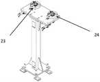
图2为本申请公开的套筒更换部的结构示意图;FIG. 2 is a schematic structural diagram of the sleeve replacement part disclosed in the application;
图3为本申请公开的套筒更换部的另一角度结构示意图;FIG. 3 is a schematic structural diagram of another angle of the sleeve replacement part disclosed in the application;
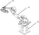
图4为本申请公开的机器人拧紧部的结构示意图;4 is a schematic structural diagram of a robot tightening portion disclosed in the application;
图5为本申请公开的拧紧机构的结构示意图。FIG. 5 is a schematic structural diagram of the tightening mechanism disclosed in the application.
附图标记说明:1、安全围栏;2、套筒更换部;21、套筒支架;22、套筒活动叉;23、套筒检测部;24、套筒定位部;3、机器人拧紧部;31、机器人底座;32、机器人本体;33、拧紧机构;4、轨道车;8、安装座;81、安装支架;82、反力支架;9、拧紧部;91、滑动导向A柱;92、拧紧枪;93、枪头配套套筒;94、滑动导向B柱;10、测量部;101、保护罩;102、高精度测量仪;11、视觉定位部。Description of reference numerals: 1. Safety fence; 2. Sleeve replacement part; 21. Sleeve bracket; 22. Sleeve movable fork; 23. Sleeve detection part; 24. Sleeve positioning part; 3. Robot tightening part; 31. Robot base; 32. Robot body; 33. Tightening mechanism; 4. Rail car; 8. Mounting seat; 81. Mounting bracket; 82. Reaction bracket; 9. Tightening part; 91. Sliding guide A-pillar; 92, Tighten the gun; 93, the matching sleeve of the gun head; 94, the sliding guide B-pillar; 10, the measuring part; 101, the protective cover; 102, the high-precision measuring instrument; 11, the visual positioning part.
具体实施方式Detailed ways
下面将结合本申请实施例中的附图,对本申请实施例中的技术方案进行清楚、完整地描述,显然,所描述的实施例仅仅是本申请一部分实施例,而不是全部的实施例。基于本申请中的实施例,本领域普通技术人员在没有做出创造性劳动前提下所获得的所有其他实施例,都属于本申请保护的范围。The technical solutions in the embodiments of the present application will be clearly and completely described below with reference to the drawings in the embodiments of the present application. Obviously, the described embodiments are only a part of the embodiments of the present application, but not all of the embodiments. Based on the embodiments in the present application, all other embodiments obtained by those of ordinary skill in the art without creative efforts shall fall within the protection scope of the present application.
实施例一Example 1
如图1所示,一种基于工业机器人的回转支承装配系统,包括相互匹配的套筒更换部2和机器人拧紧部3。其中,如图1、图4所示,套筒更换部2用于供机器人拧紧部3替换套筒。机器人拧紧部3由机器人底座31、固定在机器人底座31上端的机器人本体32和由机器人本体32驱动移动的拧紧机构33组成。拧紧机构33用于确定回转支承的中心和基准点位置,并获取待拧紧螺栓的中心位置和驱动套筒将螺栓头部拧紧至设定扭矩。因此,通过机器人本体32和拧紧机构33协同实现通过机器认本体驱动拧紧机构33的移动,再在拧紧机构33的作业下完成回转支承的螺栓拧紧作业。与此同时,机器人底座31支承着机器人本体32,并通过抬高机器人本体32的高度,使机器人本体32用于拧紧较高的工件。As shown in FIG. 1 , an industrial robot-based slewing bearing assembly system includes a
如图1所示,该基于工业机器人的回转支承装配系统还包括包围套筒更换部2和机器人拧紧部3的安全围栏1和用于运载回转支承和零件的轨道车4。其中,在安全围栏1的开口处设置有激光光幕,且激光光幕用于在人员或异物进入安全围栏1内时发出警报,以通过警报的方式以在该基于工业机器人的回转支承装配系统作业时防止有人员或异物进入安全围栏1内而发生意外。As shown in FIG. 1 , the industrial robot-based slewing ring assembly system also includes a
与此同时,套筒更换部2与机器人拧紧部3均设置有两个并对称分布在回转支承行进方向的两侧,以相互协同的方式进行螺栓的拧紧作业。At the same time, the
如图2、图3所示,套筒更换部2包括套筒支架21以及固定在套筒支架21上的套筒活动叉22、套筒检测部23和套筒定位部24。其中,套筒定位部24用于与拧紧机构33垂直匹配,以回收和替换不同规格和型号的套筒。套筒检测部23用于检测拧紧机构33与套筒定位部24的定位匹配,且套筒活动叉22由气缸驱动运行,并用于插入套筒中心O型槽连接固定。As shown in FIGS. 2 and 3 , the
如图1、图5所示,拧紧部9包括安装座8、拧紧部9、测量部10和视觉定位部11。其中,拧紧部9和测量部10分别固定在安装座8的两端,且拧紧部9用于拧紧螺栓,测量部10用于测量螺栓。视觉定位部11位于安装座8的底部,并用于确定回转支承的中心和基准点位置。As shown in FIG. 1 and FIG. 5 , the tightening
需要说明的是,安装座8包括安装支架81和反力支架82。其中,安装座8用于提供安装平台,并与机器人本体32连接。反力支架82用于在拧紧作业时卸载扭力,具体的,在螺栓拧紧时通过靠紧零件表面以卸载作用于其上来自拧紧枪92的强大扭力,从而达到拧紧时保护机器人本体32的目的。It should be noted that the mounting
与此同时,拧紧部9包括滑动导向A柱91、滑动导向B柱94、拧紧枪92和枪头配套套筒93。其中,拧紧枪92为电动高精度拧紧枪,并用于固定套筒和驱动套筒拧紧螺栓。滑动导向B柱94套接有弹簧,并用于在拧紧螺栓时将拧紧枪92上的套筒压紧在螺栓头部上以补偿螺栓头部拧紧过程中的移动。测量部10包括保护罩101和高精度测量仪102。高精度测量仪102用于扫描初步固定在回转支承上的螺栓头部的垫圈外缘并获取螺栓中心位置。且视觉定位部11由工业相机和视觉控制器组成。其中,工业相机用于对回转支承和基准点拍照以获得位置照片,并将照片传送至视觉控制器。视觉控制器用于计算获取准确坐标,并将准确坐标传送至所述测量部10。At the same time, the tightening
具体的,该机器人拧紧部3的运行包括如下步骤:Specifically, the operation of the
步骤1、视觉定位部11对回转支承拍照并确定回转支承的中心和基准点位置;
步骤2、测量部10扫描螺栓并确定螺栓的中心位置,若套筒与螺栓匹配,则继续步骤3,否则继续步骤4;
步骤3、机器人本体32驱动机器人拧紧部3,令机器人拧紧部3驱动套筒套入回转支承上的螺栓头部内并拧紧螺栓至设定扭矩,再拧紧半圈;
步骤4、测量部10扫描确认回转支承上螺栓拧紧状态,若已完成全部螺栓拧紧作业,则停止运行,否则继续步骤2;
步骤5、机器人本体32驱动拧紧部9移动至套筒更换部2替换适配套筒,并继续步骤2。Step 5. The
实施例二
实施例二与实施例一的区别在于,实施例二中的两个机器人拧紧部3分别用于测量和拧紧螺栓。The difference between the second embodiment and the first embodiment is that the two
综上所示,本申请提供了一种基于工业机器人的回转支承装配系统,该基于工业机器人的回转支承装配系统通过安全围栏1包围套筒更换部2、机器人拧紧部3和轨道车4,并在安全围栏1的开口处设置有激光光幕,并通过警报的方式以在该基于工业机器人的回转支承装配系统作业时防止有人员或异物进入安全围栏1内而发生意外;并通过测量部10对螺栓头部的扫描,以在测量确定螺栓中心位置的同时,通过机器人本体32驱动电动高精度拧紧枪实现回转支承上的螺栓的全自动拧紧,从而显著提高拧紧效率和装配质量,有效降低人工操作的劳动强度。To sum up, the present application provides a slewing bearing assembly system based on an industrial robot. The industrial robot-based slewing bearing assembly system surrounds the
与此同时,在进行套筒的替换时,首先通过机器人本体32驱动拧紧部9移动到拧紧枪92与套筒定位部24同轴在其下方一定距离处,再垂直向上移动,直到套筒进入套筒定位部24后,通过气缸带动套筒活动叉22前伸,使套筒活动叉22插入套筒O型槽中,进而再通过拧紧部9垂直下移,使得套筒从拧紧枪92转移至套筒更换部2,进而再使得机器人本体32移动到套筒定位部24下方垂直上移,使拧紧枪92插入另一个套筒中,此时通过气缸带动套筒活动叉22缩回,机器人本体32继续拧紧回转支承上剩下螺栓,达到提升套筒替换效率的效果。At the same time, when replacing the sleeve, the
本申请涉及的“第一”、“第二”、“第三”、“第四”等(如果存在)是用于区别类似的对象,而不必用于描述特定的顺序或先后次序。应该理解这样使用的数据在适当情况下可以互换,以便这里描述的实施例能够以除了在这里图示或描述的内容以外的顺序实施。此外,术语“包括”和“具有”以及他们的任何变形,意图在于覆盖不排他的包含,例如,包含了一系列步骤或单元的过程、方法或设备不必限于清楚地列出的那些步骤或单元,而是可包括没有清楚地列出的或对于这些过程、方法或设备固有的其它步骤或单元。References in this application to "first", "second", "third", "fourth", etc. (if any) are used to distinguish similar objects and are not necessarily used to describe a specific order or sequence. It is to be understood that data so used may be interchanged under appropriate circumstances so that the embodiments described herein can be practiced in sequences other than those illustrated or described herein. Furthermore, the terms "comprising" and "having", and any variations thereof, are intended to cover non-exclusive inclusion, for example, a process, method or apparatus comprising a series of steps or elements is not necessarily limited to those steps or elements expressly listed , but may include other steps or elements not expressly listed or inherent to these processes, methods or apparatus.
需要说明的是,在本申请中涉及“第一”、“第二”等的描述仅用于描述目的,而不能理解为指示或暗示其相对重要性或者隐含指明所指示的技术特征的数量。由此,限定有“第一”、“第二”的特征可以明示或者隐含地包括至少一个该特征。另外,各个实施例之间的技术方案可以相互结合,但是必须是以本领域普通技术人员能够实现为基础,当技术方案的结合出现相互矛盾或无法实现时应当认为这种技术方案的结合不存在,也不在本申请要求的保护范围之内。It should be noted that the descriptions involving "first", "second", etc. in this application are only for the purpose of description, and should not be construed as indicating or implying their relative importance or implying the number of indicated technical features . Thus, a feature delimited with "first", "second" may expressly or implicitly include at least one of that feature. In addition, the technical solutions between the various embodiments can be combined with each other, but must be based on the realization by those of ordinary skill in the art. When the combination of technical solutions is contradictory or cannot be realized, it should be considered that the combination of such technical solutions does not exist. , is not within the scope of protection claimed in this application.
本文中应用了具体个例对本申请的原理及实施方式进行了阐述,以上实施例的说明只是用于帮助理解本申请的方法及其核心思想;同时,对于本领域的一般技术人员,依据本申请的思想,在具体实施方式及应用范围上均会有改变之处,综上所述,本说明书内容不应理解为对本申请的限制。The principles and implementations of the present application are described herein by using specific examples. The descriptions of the above embodiments are only used to help understand the methods and core ideas of the present application. There will be changes in the specific implementation and application scope. To sum up, the content of this specification should not be construed as a limitation to the application.
Claims (10)
Priority Applications (1)
| Application Number | Priority Date | Filing Date | Title |
|---|---|---|---|
| CN202210452471.0ACN114633102A (en) | 2022-04-27 | 2022-04-27 | A slewing bearing assembly system based on industrial robots |
Applications Claiming Priority (1)
| Application Number | Priority Date | Filing Date | Title |
|---|---|---|---|
| CN202210452471.0ACN114633102A (en) | 2022-04-27 | 2022-04-27 | A slewing bearing assembly system based on industrial robots |
Publications (1)
| Publication Number | Publication Date |
|---|---|
| CN114633102Atrue CN114633102A (en) | 2022-06-17 |
Family
ID=81951953
Family Applications (1)
| Application Number | Title | Priority Date | Filing Date |
|---|---|---|---|
| CN202210452471.0AWithdrawnCN114633102A (en) | 2022-04-27 | 2022-04-27 | A slewing bearing assembly system based on industrial robots |
Country Status (1)
| Country | Link |
|---|---|
| CN (1) | CN114633102A (en) |
Cited By (6)
| Publication number | Priority date | Publication date | Assignee | Title |
|---|---|---|---|---|
| CN115255896A (en)* | 2022-06-30 | 2022-11-01 | 武汉武铁机辆装备有限公司 | Wheel-mounted brake disc robot bolt tightening platform |
| CN116532957A (en)* | 2022-11-30 | 2023-08-04 | 江苏金陵智造研究院有限公司 | Man-machine cooperation assembly station for large-diameter cylindrical section products and working method thereof |
| CN116690470A (en)* | 2023-05-30 | 2023-09-05 | 华昌达智能装备集团股份有限公司 | An automatic bolt tightening device and a workpiece processing device |
| CN116765803A (en)* | 2023-06-20 | 2023-09-19 | 华南理工大学 | An intelligent flexible bolt tightening control system, method and device |
| CN117140061A (en)* | 2023-10-18 | 2023-12-01 | 徐工集团工程机械股份有限公司建设机械分公司 | Automatic screwing device and method for turntable slewing bearing |
| CN117226493A (en)* | 2023-09-25 | 2023-12-15 | 内蒙古明阳北方智慧能源研发中心有限公司 | Automatic tightening device for bolts of driving chain locking disc of wind generating set |
Citations (5)
| Publication number | Priority date | Publication date | Assignee | Title |
|---|---|---|---|---|
| JPH10138057A (en)* | 1996-11-08 | 1998-05-26 | Nachi Fujikoshi Corp | Automatic fastening and loosening device for form fastening bolt |
| CN108213937A (en)* | 2018-02-28 | 2018-06-29 | 中船重工鹏力(南京)智能装备系统有限公司 | A kind of large-sized bolt Full-automatic reverse torsion twists bolt device |
| CN209407870U (en)* | 2018-12-28 | 2019-09-20 | 新松机器人联合研究院(湘潭)有限公司 | A kind of dual robot bolt automatic tightening system being arranged symmetrically |
| CN111805224A (en)* | 2020-08-07 | 2020-10-23 | 上汽通用五菱汽车股份有限公司 | Automatic sleeve replacing system for bolt tightening station |
| CN217045357U (en)* | 2022-04-27 | 2022-07-26 | 浙江希尔机器人股份有限公司 | Slewing bearing assembly system |
- 2022
- 2022-04-27CNCN202210452471.0Apatent/CN114633102A/ennot_activeWithdrawn
Patent Citations (5)
| Publication number | Priority date | Publication date | Assignee | Title |
|---|---|---|---|---|
| JPH10138057A (en)* | 1996-11-08 | 1998-05-26 | Nachi Fujikoshi Corp | Automatic fastening and loosening device for form fastening bolt |
| CN108213937A (en)* | 2018-02-28 | 2018-06-29 | 中船重工鹏力(南京)智能装备系统有限公司 | A kind of large-sized bolt Full-automatic reverse torsion twists bolt device |
| CN209407870U (en)* | 2018-12-28 | 2019-09-20 | 新松机器人联合研究院(湘潭)有限公司 | A kind of dual robot bolt automatic tightening system being arranged symmetrically |
| CN111805224A (en)* | 2020-08-07 | 2020-10-23 | 上汽通用五菱汽车股份有限公司 | Automatic sleeve replacing system for bolt tightening station |
| CN217045357U (en)* | 2022-04-27 | 2022-07-26 | 浙江希尔机器人股份有限公司 | Slewing bearing assembly system |
Cited By (7)
| Publication number | Priority date | Publication date | Assignee | Title |
|---|---|---|---|---|
| CN115255896A (en)* | 2022-06-30 | 2022-11-01 | 武汉武铁机辆装备有限公司 | Wheel-mounted brake disc robot bolt tightening platform |
| CN115255896B (en)* | 2022-06-30 | 2024-02-27 | 武汉武铁机辆装备有限公司 | Wheel dress brake disc robot bolt tightening platform |
| CN116532957A (en)* | 2022-11-30 | 2023-08-04 | 江苏金陵智造研究院有限公司 | Man-machine cooperation assembly station for large-diameter cylindrical section products and working method thereof |
| CN116690470A (en)* | 2023-05-30 | 2023-09-05 | 华昌达智能装备集团股份有限公司 | An automatic bolt tightening device and a workpiece processing device |
| CN116765803A (en)* | 2023-06-20 | 2023-09-19 | 华南理工大学 | An intelligent flexible bolt tightening control system, method and device |
| CN117226493A (en)* | 2023-09-25 | 2023-12-15 | 内蒙古明阳北方智慧能源研发中心有限公司 | Automatic tightening device for bolts of driving chain locking disc of wind generating set |
| CN117140061A (en)* | 2023-10-18 | 2023-12-01 | 徐工集团工程机械股份有限公司建设机械分公司 | Automatic screwing device and method for turntable slewing bearing |
Similar Documents
| Publication | Publication Date | Title |
|---|---|---|
| CN114633102A (en) | A slewing bearing assembly system based on industrial robots | |
| CN103846606B (en) | Welding track based on machine vision corrects Special testing device and method | |
| CN111761345A (en) | Intelligent robot air spring double-shaft automatic tightening system and method | |
| CN112059363A (en) | An unmanned wall-climbing welding robot based on vision measurement and its welding method | |
| CN201309054Y (en) | Electric locomotive top cover positive assembling tool | |
| CN212329961U (en) | Unmanned wall welding robot that climbs based on vision measurement | |
| CN116586880B (en) | Clamping device for welding U-shaped rib plates | |
| CN113042926A (en) | Automatic welding device and method for flange rib plate of electric power tower | |
| CN217045357U (en) | Slewing bearing assembly system | |
| CN115945905B (en) | Automatic tightening control system based on binocular vision recognition and positioning | |
| CN116571997A (en) | Water pipe pressure equipment mechanism of box under new energy automobile | |
| CN211601876U (en) | Micro-aperture measuring device | |
| CN211085124U (en) | Detection apparatus for needle arrangement distance is kept somewhere to Y formula | |
| CN205464888U (en) | Gantry welding machine | |
| CN210051703U (en) | Automatic wheel detection device | |
| CN217859283U (en) | Pressure resistance welding device | |
| CN115511906A (en) | Power battery box disassembling method | |
| CN212761692U (en) | Thin-wall large-diameter winding drum correction and spot welding auxiliary integrated machine | |
| CN217808581U (en) | Automatic turning device of wheel set | |
| CN218079727U (en) | Automatic correcting equipment for horizontal motorcycle frame | |
| JP2623049B2 (en) | Automatic large assembly equipment | |
| CN217452728U (en) | Automobile welding positioning sliding mechanism | |
| CN114268188A (en) | Large corrugated pipe final assembly method | |
| CN116423170B (en) | Steering pull rod machining process | |
| CN211085192U (en) | Middle shaft assembly and input/output end spline missing tooth relative angle detection table |
Legal Events
| Date | Code | Title | Description |
|---|---|---|---|
| PB01 | Publication | ||
| PB01 | Publication | ||
| SE01 | Entry into force of request for substantive examination | ||
| SE01 | Entry into force of request for substantive examination | ||
| WW01 | Invention patent application withdrawn after publication | Application publication date:20220617 | |
| WW01 | Invention patent application withdrawn after publication |