CN114620092A - Mobile water supply and drainage equipment and method suitable for motor train unit parked at side edge of high platform - Google Patents
Mobile water supply and drainage equipment and method suitable for motor train unit parked at side edge of high platformDownload PDFInfo
- Publication number
- CN114620092A CN114620092ACN202210070953.XACN202210070953ACN114620092ACN 114620092 ACN114620092 ACN 114620092ACN 202210070953 ACN202210070953 ACN 202210070953ACN 114620092 ACN114620092 ACN 114620092A
- Authority
- CN
- China
- Prior art keywords
- hose
- guide groove
- conduit
- guide
- emu
- Prior art date
- Legal status (The legal status is an assumption and is not a legal conclusion. Google has not performed a legal analysis and makes no representation as to the accuracy of the status listed.)
- Granted
Links
Images


Classifications
- B—PERFORMING OPERATIONS; TRANSPORTING
- B61—RAILWAYS
- B61K—AUXILIARY EQUIPMENT SPECIALLY ADAPTED FOR RAILWAYS, NOT OTHERWISE PROVIDED FOR
- B61K11/00—Serving peculiar to locomotives, e.g. filling with, or emptying of, water, sand, or the like at the depots
Landscapes
- Engineering & Computer Science (AREA)
- Mechanical Engineering (AREA)
- Vehicle Cleaning, Maintenance, Repair, Refitting, And Outriggers (AREA)
- Sewage (AREA)
Abstract
Description
Translated fromChinese技术领域technical field
本发明涉及铁路列车上下水技术领域,具体的是一种适应高站台侧边停放的动车组的移动上下水设备,还是一种适应高站台侧边停放的动车组的移动上下水方法。The present invention relates to the technical field of water loading and unloading of railway trains, in particular to a mobile water loading and unloading equipment suitable for EMUs parked on the side of high platforms, and a mobile water loading and unloading method suitable for EMUs parked on the sides of high platforms.
背景技术Background technique
现有铁路移动卸污车,一般用于动车存车场和客车整备所。移动卸污车通过软管连接动车(客车)集便器的污物箱,收集其中污物。The existing railway mobile sewage unloading vehicles are generally used in motor car storage yards and passenger car maintenance stations. The mobile sewage unloading truck is connected to the dirt box of the toilet of the motor car (passenger car) through a hose to collect the dirt in it.
在夜间到发线停放动车组的车站,需要为停放的动车组卸污,目前的方法是:At the station where the EMUs are parked on the arrival and departure lines at night, it is necessary to unload the parked EMUs. The current method is:
方法1.停放动车组的车站配套固定卸污设施。Method 1. Stations where EMUs are parked are equipped with fixed unloading facilities.
方法2.动车组在有卸污设施的车站完成卸污作业之后再到指定车站停放。Method 2. The EMU will park at the designated station after completing the discharge operation at the station with the discharge facility.
方法3.用移动卸污车卸污,因为高站台遮挡停放在高站台侧边的动车组一侧的卸污口,卸污车停在与动车组隔着一条未停放动车组的到发线的旁边的站台上,卸污软管跨过到发线与动车组另一侧的卸污口相连。Method 3. Use a mobile unloading truck to unload the waste, because the high platform blocks the unloading port on the side of the EMU parked on the side of the high platform, and the unloading truck is parked at the arrival and departure line of the unparked EMU separated from the EMU. On the platform next to the station, the sewage discharge hose is connected to the sewage discharge port on the other side of the EMU across the arrival and departure line.
方法4.用移动卸污车卸污,打开车门,卸污软管通过车端过道,与离远一侧的卸污口相连。Method 4. Use a mobile unloading truck to unload the waste, open the door, and the unloading hose passes through the aisle at the end of the vehicle and is connected to the unloading port on the far side.
在上述方法1中,固定卸污设施的投资较多,是移动卸污车的十倍左右,一般用于卸污作业量较大的动车所和大型客运站,而夜间停放动车组的中间站,适用于移动卸污车。In the above method 1, the investment in fixed unloading facilities is more, which is about ten times that of mobile unloading vehicles. Generally, it is used for EMUs and large passenger stations with a large amount of sewage unloading operations, and the intermediate stations of EMUs are parked at night. , suitable for mobile unloading trucks.
在上述方法2中,如果在列车运行途中卸污,会增加旅客旅行时间,少则十几、多则四十多分钟;如果列车到终点站完成终到作业后,再空跑到附近有卸污设施的地方卸污,这样的条件很少车站能够具备,而且明显不方便、也不经济。In the above method 2, if the pollution is unloaded during the operation of the train, it will increase the travel time of passengers, ranging from a dozen to more than 40 minutes; It is not convenient and economical to discharge sewage at the place where the sewage facilities are located. Few stations can have such conditions.
在上述方法3中,软管跨越未停车的到发线,作业不方便,也不规范,还要增加作业人员(由2人增加到6人~7人)。一旦想跨越的到发线停放了动车组,此法即不可行。In the above-mentioned method 3, the hose crosses the unstopped arrival and departure line, which is inconvenient and normative in operation, and requires additional operators (from 2 to 6 to 7). Once the EMU is parked on the arrival and departure line that you want to cross, this method is not feasible.
在上述方法4中,夜间卸污期间打开车门,动车组内处在开放状态,既不规范,又有隐患,还可能污染车内过道,也要增加作业人员。In the above-mentioned method 4, the door is opened during the discharge of pollutants at night, and the EMU is in an open state, which is not standardized and has hidden dangers. It may also pollute the aisles in the car, and the number of operators should be increased.
因此,需要解决高站台侧边停放的动车组的卸污口与移动卸污设备的连接问题,以便未设置固定卸污设施的高铁车站,能够使用移动卸污设备,为夜间停放的动车组卸污。Therefore, it is necessary to solve the connection problem between the sewage discharge port of the EMU parked on the side of the high platform and the mobile sewage discharge equipment, so that the high-speed rail station without fixed sewage discharge facilities can use the mobile sewage discharge equipment to unload the EMU parked at night. Sewage.
此外,有些夜间停放动车组的高铁车站没有上水设施而又需要为动车组上水。目前的上水设施是在车站到发线之间设置固定的上水管道、上水井和上水软管,投资较大,在需要上水的列车较少时设置所述上水设施不经济。而在既有未设上水设施的车站增设所述上水设施,不仅投资较大,而且工程施工与现有客运作业互相影响。因此,在需要上水的列车较少的车站,可考虑在站台上使用移动上水设备给车辆上水。移动上水设备包括移动上水车和连接移动上水车和车辆上水口的软管,与上述移动卸污设备一样,移动上水设备也需解决高站台侧边停放的动车组的上水口与移动上水设备的连接问题。In addition, some high-speed rail stations where EMUs are parked at night do not have water supply facilities and need to supply water for EMUs. The current water supply facility is to set up fixed water supply pipes, water supply wells and water supply hoses between the station and the departure line, which requires a large investment and is uneconomical to install the water supply facilities when there are few trains that need water supply. However, adding the above-mentioned water-feeding facilities at the existing stations without water-feeding facilities will not only require a large investment, but also the engineering construction and the existing passenger transport operations will interact with each other. Therefore, at stations with few trains that need to be watered, consider using mobile water filling equipment to water the vehicles on the platform. The mobile water feeding equipment includes the mobile water feeding truck and the hose connecting the mobile water feeding truck and the water inlet of the vehicle. Like the above mobile sewage unloading equipment, the mobile water feeding equipment also needs to solve the problem of the water inlet and the water inlet of the EMU parked on the side of the high platform. Connection problem with mobile water supply equipment.
发明内容SUMMARY OF THE INVENTION
为了解决动车组在高铁站到发线停放时的上下水问题,本发明提供了一种适应高站台侧边停放的动车组的移动上下水设备和方法,该适应高站台侧边停放的动车组的移动上下水设备和方法比固定卸污设施节省投资,可避免在旅行途中停站等候上下水,不用跨线或打开车门进行不规范的作业。In order to solve the problem of water loading and unloading when the EMU is parked on the arrival and departure line of the high-speed railway station, the present invention provides a mobile water and water device and method suitable for the EMU parked on the side of the high platform. Compared with fixed sewage unloading facilities, the mobile water and sewage equipment and method saves investment, can avoid stopping to wait for water and water during the journey, and do not need to cross the line or open the door to perform irregular operations.
本发明解决其技术问题所采用的技术方案是:The technical scheme adopted by the present invention to solve its technical problems is:
一种适应高站台侧边停放的动车组的移动上下水设备,包括卸污车或上水车,所述卸污车或上水车连接有软管,所述适应高站台侧边停放的动车组的移动上下水设备还包括:A mobile water loading and unloading device adapted to an EMU parked on the side of a high platform, comprising a sewage unloading truck or a water loading truck, wherein the sewage unloading or loading truck is connected with a hose, and the device is adapted to the high platform side parked high-speed train. The group's mobile plumbing equipment also includes:
导管,导管内能够套设所述卸污车或上水车的软管;A conduit, in which the hose of the sewage unloading truck or the water loading truck can be sheathed;
导槽,整体横断面或部分横断面为U形结构,导槽能够横亘在轨道上,导槽的开口朝上;Guide groove, the overall cross section or part of the cross section is a U-shaped structure, the guide groove can lie on the track, and the opening of the guide groove is upward;
导筒,含有筒体,筒体为筒形结构;The guide cylinder includes a cylinder body, and the cylinder body is a cylindrical structure;
当导筒插入风挡和高站台之间时,导筒与导槽上下对应,导筒的入口端朝上,导筒的出口端朝向导槽;When the guide cylinder is inserted between the windshield and the high platform, the guide cylinder corresponds to the guide groove up and down, the inlet end of the guide cylinder faces upwards, and the outlet end of the guide cylinder faces the guide groove;
当导管插入导筒时,导管与导槽上下对应,导管的入口端朝上,导管的出口端朝向导槽;When the catheter is inserted into the guide cylinder, the catheter and the guide groove correspond up and down, the inlet end of the catheter is upward, and the outlet end of the catheter is facing the guide groove;
所述卸污车或上水车的软管能够由人工推动并由导管和导槽引导从所述动车组靠近站台的一侧到达另一侧。The hoses of the sewage unloading truck or the water loading truck can be manually pushed and guided by pipes and guide grooves from one side of the EMU close to the platform to the other side.
一种适应高站台侧边停放的动车组的移动上下水方法,所述适应高站台侧边停放的动车组的移动上下水方法采用了上述的适应高站台侧边停放的动车组的移动上下水设备,所述适应高站台侧边停放的动车组的移动上下水方法包括以下步骤:A method for moving up and down water for EMUs parked on the side of high platforms, the method for moving up and down the water for EMUs parked on the sides of high platforms adopts the above-mentioned moving up and down methods for EMUs parked on the sides of high platforms Equipment, the method for moving up and down water for the EMUs parked on the side of the high platform includes the following steps:
步骤1、所述动车组停放于高站台的侧边,所述卸污车或上水车走行在高站台上,靠近风挡停稳;Step 1. The EMU is parked on the side of the high platform, and the sewage unloading truck or the water loading truck walks on the high platform and stops close to the windshield;
步骤2、将导筒的筒体插入风挡和高站台之间,导筒的垫板落在高站台上,将导槽横亘在风挡下方的轨道上,导槽的一端位于导筒的下方;Step 2. Insert the cylinder of the guide cylinder between the windshield and the high platform, the backing plate of the guide cylinder falls on the high platform, and the guide groove lies on the track under the windshield, and one end of the guide groove is located below the guide cylinder;
步骤3、导管和套设于导管内的软管在导筒的筒体内同步下放,导管的把手接触导筒止挡件,导管的把手与导筒止挡件钩挂连接固定,软管的下端落在导槽内;Step 3. The catheter and the hose sheathed in the catheter are lowered simultaneously in the barrel of the guide cylinder, the handle of the catheter contacts the guide cylinder stopper, the handle of the catheter and the guide cylinder stopper are hooked and fixed, and the lower end of the hose fall in the guide groove;
步骤4、使软管在导管内向下移动,软管受到导槽的约束、导向并顺着导槽移动至所述动车组的另一侧;Step 4. Make the hose move downward in the conduit, and the hose is constrained and guided by the guide groove and moves to the other side of the EMU along the guide groove;
步骤5、将软管下端与所述动车组的卸污口或上水口连接;Step 5. Connect the lower end of the hose to the sewage discharge port or the water supply port of the EMU;
步骤6、所述动车组卸污或上水。
本发明的有益效果是:在动车组的车体与高站台、轨道之间空间狭窄、不能按常规方式用软管连接卸污车(或上水车)和车辆卸污口(或上水口)的条件下,通过导管推动软管在狭窄空间内定向穿行,通过导槽引导软管穿过动车组与轨道之间的狭窄空间,从而实现用软管连接停在高站台的卸污车(或上水车)和车辆卸污口(或上水口);利用置于风挡和站台之间的导筒、车体与轨道之间的导槽,隔开车体与导管、软管和接头,从而避免伤及车体外表面;采用本发明的移动卸污(或上水)设备,比固定卸污设施节省投资,可避免在旅行途中停站等候卸污(或上水),不用跨线或打开车门进行不规范的作业。The beneficial effects of the present invention are: the space between the car body of the EMU, the high platform and the track is narrow, and it is impossible to connect the sewage unloading truck (or the water truck) and the vehicle sewage discharge port (or the water opening) with a hose in a conventional way. Under certain conditions, the hose is pushed through the conduit to pass through the narrow space, and the guide groove is used to guide the hose through the narrow space between the EMU and the track, so as to connect the unloading truck (or Water car) and vehicle sewage discharge port (or water inlet); use the guide tube between the windshield and the platform, the guide groove between the car body and the track, and separate the car body from the conduit, hose and joint, so as to Avoid hurting the outer surface of the vehicle; using the mobile sewage unloading (or watering) equipment of the present invention saves investment compared to fixed sewage unloading facilities, and can avoid stopping to wait for sewage (or watering) during the trip, without crossing the line or opening Irregular work on the door.
附图说明Description of drawings
构成本申请的一部分的说明书附图用来提供对本发明的进一步理解,本发明的示意性实施例及其说明用于解释本发明,并不构成对本发明的不当限定。The accompanying drawings forming a part of the present application are used to provide further understanding of the present invention, and the exemplary embodiments of the present invention and their descriptions are used to explain the present invention and do not constitute an improper limitation of the present invention.
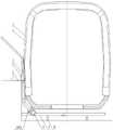
图1是本发明所述适应高站台侧边停放的动车组的移动上下水设备的工作状态示意图。FIG. 1 is a schematic view of the working state of the mobile water and water equipment for an EMU that is adapted to be parked on the side of a high platform according to the present invention.
图2是导筒的主视示意图。Figure 2 is a schematic front view of the guide cylinder.
图3是导筒的俯视示意图。FIG. 3 is a schematic top view of the guide cylinder.
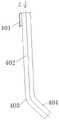
图4是第一种导管的主视示意图。Figure 4 is a schematic front view of the first catheter.
图5是图4中A方向的示意图。FIG. 5 is a schematic diagram of the direction A in FIG. 4 .
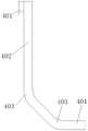
图6是第二种导管的主视示意图。Figure 6 is a schematic front view of a second type of catheter.
图7是导槽含有合页时的主视示意图。FIG. 7 is a schematic front view when the guide groove includes a hinge.
图8是导槽含有合页时的俯视示意图。FIG. 8 is a schematic top view when the guide groove includes a hinge.
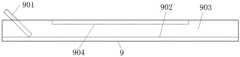
图9是导槽含有端板时的主视示意图。Fig. 9 is a schematic front view of the guide groove including the end plate.
1、车体中部;2、风挡;3、软管;4、导管;5、导筒;6、导筒止挡件;7、高站台;8、快速接头;9、导槽;10、轨道;11、合页;1. The middle of the car body; 2. The windshield; 3. The hose; 4. The conduit; 5. The guide tube; 6. The guide tube stopper; 7. The high platform; ; 11. Hinge;
401、把手;402、上直段;403、折弯段;404、下直段;401, handle; 402, upper straight section; 403, bending section; 404, lower straight section;
501、筒体;502、垫板;503、护板;504、通孔;501, cylinder body; 502, backing plate; 503, guard plate; 504, through hole;
601、平板段;602、立板段;601, flat plate section; 602, vertical plate section;
801、紧固把手;801. Fasten the handle;
901、端板;902、底板;903、侧板;904、顶板。901, end plate; 902, bottom plate; 903, side plate; 904, top plate.
车体中部1是指动车组的车体(俗称车厢)的中间部分,区别于车体端部的风挡2,两者都是车体组成部分,为在叙述中有所区分,因而分别定义。The middle part of the car body 1 refers to the middle part of the car body (commonly known as the carriage) of the EMU, which is different from the windshield 2 at the end of the car body. Both are parts of the car body.
具体实施方式Detailed ways
需要说明的是,在不冲突的情况下,本申请中的实施例及实施例中的特征可以相互组合。下面将参考附图并结合实施例来详细说明本发明。It should be noted that the embodiments in the present application and the features of the embodiments may be combined with each other in the case of no conflict. The present invention will be described in detail below with reference to the accompanying drawings and in conjunction with the embodiments.
一种适应高站台侧边停放的动车组的移动上下水设备,包括卸污车或上水车(即常规的移动卸污车或上水车),所述卸污车或上水车连接有软管3,所述适应高站台侧边停放的动车组的移动上下水设备还包括:A mobile water loading and unloading device adapted to the EMU parked on the side of a high platform, including a sewage unloading truck or a water loading truck (that is, a conventional mobile sewage unloading truck or a water loading truck), and the sewage unloading or loading truck is connected with a The hose 3, the mobile water and water equipment adapted to the EMU parked on the side of the high platform also includes:
导管4,导管4内能够套设所述卸污车或上水车的软管3;The conduit 4, the hose 3 of the sewage unloading truck or the water loading truck can be sleeved in the conduit 4;
导槽9,整体横断面或部分横断面为U形结构,导槽9能够横亘在轨道10上,导槽9的开口朝上;The guide groove 9 has a U-shaped structure in the overall cross section or part of the cross section, the guide groove 9 can lie on the track 10, and the opening of the guide groove 9 faces upward;
导筒5,含有筒体501,筒体501为筒形结构;The guide cylinder 5 includes a
当导筒5插入风挡2和高站台7之间时,导筒5与导槽9上下对应,导筒5的入口端朝上,导筒5的出口端朝向导槽9;When the guide cylinder 5 is inserted between the windshield 2 and the high platform 7, the guide cylinder 5 corresponds to the guide groove 9 up and down, the inlet end of the guide cylinder 5 faces upwards, and the outlet end of the guide cylinder 5 faces the guide groove 9;
当导管4插入导筒5时,导管4与导槽9上下对应,导管4的入口端朝上,导管4的出口端朝向导槽9;When the conduit 4 is inserted into the guide cylinder 5, the conduit 4 corresponds to the guide slot 9 up and down, the inlet end of the conduit 4 faces upwards, and the outlet end of the conduit 4 faces the guide slot 9;
所述卸污车或上水车的软管3能够由人工推动并由导管4和导槽9引导,从所述动车组靠近站台的一侧到达所述动车组的另一侧,如图1所示。The hose 3 of the sewage unloading truck or the water loading truck can be manually pushed and guided by the conduit 4 and the guide groove 9, from the side of the EMU close to the platform to the other side of the EMU, as shown in Figure 1 shown.
为防止旅客上下车时踩空,车体与高站台7之间的空隙宽度在100毫米左右,软管3(外径小于等于76毫米)和快速接头8(外径87毫米、两把手外轮廓线之间最大距离约210毫米)不易通过,而且可能损伤动车组外皮;车体与轨道之间只有200多毫米的净空,容不下人工作业。对此,本发明利用车体端部的风挡部位(即相邻的两节车厢之间的风挡2)与高站台7之间有所加大的空隙宽度(大于115毫米),提供一种套着卸污软管3的导管4,导管4通过风挡2与高站台7之间的空隙向下移动,导管4底部到达车体下方,卸污软管3顺着导管4由手工推动,软管3的下端抵达车体下方的人工放置的导槽9之后,顺着导槽9移动到车体另一侧,作业人员拾起软管,通过软管接头(如快速接头8)与车辆卸污口相连。移动上水的上水管连接与上述方式相同。In order to prevent passengers from stepping on the bus when getting on and off the bus, the width of the gap between the car body and the high platform 7 is about 100 mm, the hose 3 (outer diameter is less than or equal to 76 mm) and the quick connector 8 (outer diameter The maximum distance between the lines is about 210 mm), which is not easy to pass, and may damage the outer skin of the EMU; there is only a clearance of more than 200 mm between the car body and the track, which cannot accommodate manual work. In this regard, the present invention utilizes the enlarged gap width (greater than 115 mm) between the windshield at the end of the vehicle body (that is, the windshield 2 between two adjacent carriages) and the high platform 7 to provide a cover The duct 4 of the unloading hose 3 moves downward through the gap between the windshield 2 and the high platform 7, the bottom of the duct 4 reaches the bottom of the vehicle body, the unloading hose 3 is manually pushed along the duct 4, and the hose After the lower end of 3 reaches the manually placed guide groove 9 under the vehicle body, it moves along the guide groove 9 to the other side of the vehicle body. mouth connected. The connection of the water supply pipe of the mobile water supply is the same as above.
在本实施例中,导槽9的整体横断面为U形结构,导槽9的上端全部为开放状态,即导槽9是通长的U形槽,导槽9可以由槽钢切割而成或由轻质材料压型而成。或者,导槽9的部分横断面为U形结构,导槽9的上端左右两侧为开放状态,导槽9的上端中部为封闭状态,即导槽9的左右两端为U形槽,导槽9的中部为筒形。导槽9的高度适应动车组与轨道之间的净空高度。In this embodiment, the overall cross section of the guide groove 9 is a U-shaped structure, and the upper ends of the guide groove 9 are all open, that is, the guide groove 9 is a U-shaped groove with a full length, and the guide groove 9 can be cut from channel steel. Or extruded from lightweight materials. Alternatively, part of the cross section of the guide groove 9 is a U-shaped structure, the upper and left sides of the guide groove 9 are in an open state, and the middle part of the upper end of the guide groove 9 is in a closed state, that is, the left and right ends of the guide groove 9 are U-shaped grooves. The middle of the groove 9 is cylindrical. The height of the guide groove 9 is adapted to the clearance height between the EMU and the track.
优选导槽9中部加上盖,即导槽9的上端左右两侧为开放状态,导槽9的上端中部为封闭状态,以免软管和接头伤及车体底部,导槽9内的净宽约为450毫米,导槽9外轮廓高度小于动车组与轨道之间净空高度(按200毫米计),导槽9的壁厚2毫米,导槽9内净高约为185毫米,导槽9的长度跨越两根轨道10并抵达高站台7的侧面,导槽9的长度约为3200毫米。It is preferable to add a cover to the middle of the guide groove 9, that is, the left and right sides of the upper end of the guide groove 9 are open, and the middle part of the upper end of the guide groove 9 is closed to prevent the hose and the joint from damaging the bottom of the vehicle body. About 450 mm, the height of the outer contour of the guide groove 9 is less than the clearance height between the EMU and the track (according to 200 mm), the wall thickness of the guide groove 9 is 2 mm, the inner height of the guide groove 9 is about 185 mm, and the guide groove 9 The length of the channel 9 spans the two rails 10 and reaches the side of the high platform 7, and the length of the guide channel 9 is about 3200 mm.
在本实施例中,导槽9含有左右设置的左半槽段和右半槽段,所述左半槽段和右半槽段之间通过合页11连接,合页11位于导槽9的下表面,导槽9能够对折,导槽9可折叠并拢而缩短长度,如图7和图8所示。不能折叠的导槽,一个人携带比较麻烦,可能需要两个人抬着,而另一方面,为了夜间作业安全起见,轨道上的作业人员派出两个人、互相照应比较好,因此,不折叠的导槽也是可行的。而可折叠的导槽9,一个人携带方便一些。In this embodiment, the guide groove 9 includes a left half groove segment and a right half groove segment arranged left and right, and the left half groove segment and the right half groove segment are connected by a
或者,导槽9的构造还可有其它的实现方式,例如,导槽9一端设有端板901,端板901与导槽9的底板902连接并成钝角,端板901与导槽9的侧板903连接固定;导槽9的上部全部为开放状态,或者,导槽9两端的上部为开放状态,导槽9中间的上部为封闭状态,导槽9的上部设有顶板904,如图9所示。Alternatively, the structure of the guide groove 9 can also be realized in other ways. For example, one end of the guide groove 9 is provided with an
在本实施例中,导筒5含有筒体501,筒体501外轮廓与风挡2和高站台7之间空隙匹配,与外轮廓不规整的导管4、软管3和快速接头8相比,筒体501比较容易插入所述空隙,让导管4、软管3和快速接头8在筒体501内穿行,以免伤及车体。筒体501的入口端的一侧外设有垫板502,垫板502与筒体501连接固定为一体,当导筒5插设于风挡2和高站台7之间时,垫板502能够平放于高站台7上。垫板502的作用在于可以使导筒5稳定的放置于风挡2和高站台7之间,垫板502还可以防止导筒5在风挡2和高站台7之间滑落,如图2至图3所示。In this embodiment, the guide cylinder 5 contains a
在本实施例中,导管4可以为弯管结构,导管4的入口方向与导管4的出口方向之间的夹角可以为45度-90度,导管4含有从上向下依次连接的上直段402、折弯段403和下直段404,折弯段403为弧形。导管4可以含有一个折弯段403或两个折弯段403,如图4和图6所示。In this embodiment, the conduit 4 can be a curved pipe structure, and the included angle between the inlet direction of the conduit 4 and the outlet direction of the conduit 4 can be 45 degrees to 90 degrees.
在本实施例中,导管4能够相对于导筒5移动和转动,垫板502上设有导筒止挡件6,导管4的上部外设有把手401,把手401能够与导筒止挡件6钩挂连接。把手401与导筒止挡件6钩挂连接的好处在于可以使导管4方便地固定于导筒5内,如图4和图5所示。In this embodiment, the guide tube 4 can move and rotate relative to the guide cylinder 5, the
在本实施例中,导管4的出口方向与把手401反向设置,例如,导管4的出口方向偏向导管4的右侧,而把手401设置于导管4的上端左侧,根据把手401的位置和朝向就可以判断出导管4的出口的位置和朝向,以便于引导软管3的另一端(可包含快速接头8)进入导槽9内。In this embodiment, the outlet direction of the conduit 4 is opposite to the
导管4的内径约为85毫米,导管4的内径大于软管3外径,导管4与软管3之间应留有足够的间隙,以确保软管3相对于导管4移动。导管4的下部折弯(下端轴线与上端轴线呈135度角,如图4所示),把手401的竖向中心线与导管4的轴线在一个平面上,把手401下端挂在导筒止挡件6上可使导管定位、防止导管4在导筒5内滑落。或者,导管4的构造还可有其它的实现方式,例如,导管4可以为直管结构,即导管4的入口方向与导管4的出口方向之间的夹角为0度。The inner diameter of the conduit 4 is about 85 mm, the inner diameter of the conduit 4 is larger than the outer diameter of the hose 3 , and there should be enough clearance between the conduit 4 and the hose 3 to ensure that the hose 3 moves relative to the conduit 4 . The lower part of the catheter 4 is bent (the axis of the lower end and the axis of the upper end are at an angle of 135 degrees, as shown in Figure 4), the vertical centerline of the
在本实施例中,导筒止挡件6为角钢,该角钢的延伸方向与轨道10的延伸方向相同,导筒止挡件6含有平板段601和立板段602,平板段601与垫板502上下层叠连接固定,把手401的下端含有凸出部,把手401的下端能够与立板段602钩挂连接,如图1、图2、图4所示。In this embodiment, the
在本实施例中,筒体501的入口端的另一侧外设有护板503,护板503与筒体501连接固定为一体,护板503的上端高于导管4的入口端,护板503能够保护车体。即图1、图2所示,筒体501的上端左侧外设有垫板502,筒体501的上端右侧外设有护板503,护板503的上端高于导管4的上端。In this embodiment, the other side of the inlet end of the
在本实施例中,筒体501含有依次连接的前侧板、右侧板、后侧板和左侧板,所述前侧板或后侧板的上部设有通孔504、便于作业人员手拿导筒5。垫板502与该左侧板之间的夹角略大于90度、以适应车体外形,护板503与该右侧板位于同一平面内。In this embodiment, the
筒体501的尺寸应该保证导管4能够顺利穿过,筒体501内净空的长度小于高站台7与风挡2之间的间隙长度(筒体501的长度大于等于500毫米),筒体501的壁厚为2毫米,筒体501的宽度小于高站台7与风挡2之间的间隙宽度(筒体501的宽度大于等于115毫米)。The size of the
在卸污作业时,所述运输车为移动卸污车,软管3为卸污软管。在上水作业时,所述运输车为移动上水车,软管3为上水软管。在卸污时,选用的软管3的直径相对较大(如DN65),在上水时,选用的软管3的直径相对较小(如DN25)。软管3应具有一定的强度和刚度,以确保手动推动软管3时,软管3能够由导管4和导槽9引导从动车组靠近站台的一侧到达动车组的另一侧,如图1所示。During the unloading operation, the transport vehicle is a mobile unloading truck, and the hose 3 is a unloading hose. During the water feeding operation, the transport vehicle is a mobile water feeding vehicle, and the hose 3 is a water feeding hose. When unloading, the diameter of the selected hose 3 is relatively large (eg DN65), and when the water is fed, the selected hose 3 has a relatively small diameter (eg DN25). The hose 3 should have a certain strength and rigidity to ensure that when the hose 3 is manually pushed, the hose 3 can be guided by the conduit 4 and the guide groove 9 from the side of the EMU near the platform to the other side of the EMU, as shown in the figure 1 shown.
软管3可以根据需要设置为一根或两根,当软管3为一根时,软管3的另一端设有快速接头8;当软管3为两根时(在卸污作业时),两根软管3并列或并排设置,一根软管3的一端与所述卸污车或上水车连接,所述一根软管3的另一端设有快速接头8,另一根软管3的一端与所述卸污车连接,所述另一根软管3的另一端能够吸扫快速接头8和所述一根软管3上的污物。软管3的另一端也可以不固定连接快速接头8,这样,不带快速接头的软管更容易穿过狭窄空间;导槽9靠近高站台7的一端可以为向上张开的的喇叭口,导槽9中部和另一端可以为轻质圆筒。The number of hoses 3 can be set to one or two as required. When there is one hose 3, the other end of the hose 3 is provided with a
所述一根软管与一个快速接头固定连接用于卸污,另一根不带快速接头的软管可吸扫用于卸污的软管和接头上的污物,吸扫作业的启动和关停由站台上的卸污车操控。这样有利于减少污物对环境的影响,而两根软管导致作业量增加。软管3的通径为DN65,软管3的外径小于等于76毫米,软管3配套通径DN65的阴端快速接头(即快速接头8),快速接头8的外径为87毫米。The one hose is fixedly connected with a quick connector for unloading, and the other hose without a quick connector can suck and sweep the dirt on the hose and the connector used for unloading. The shutdown is handled by the dump truck on the platform. This helps reduce the impact of dirt on the environment, while the two hoses result in increased workload. The diameter of the hose 3 is DN65, the outer diameter of the hose 3 is less than or equal to 76 mm, and the hose 3 is matched with a female end quick connector (ie quick connector 8) with a diameter of DN65, and the outer diameter of the
软管3与快速接头8固定连接时,快速接头8由人工连接至动车组的卸污口(或上水口)。软管3与快速接头8也可在作业时连接,此时,快速接头8为双阴快速接头,双阴快速接头的两端分别由人工连接软管3和车辆卸污口(或上水口);作业时轨道上的作业人员需要随手带着双阴快速接头,在软管3按上述作业过程抵达车辆卸污口附近时,通过双阴快速接头连接软管3和卸污口(或上水口);这样,可以避免尺寸比软管3大一些的快速接头8穿过导筒5和导槽9,方便站台上的作业人员推动软管,而轨道上的作业人员负担略有加重。When the hose 3 is fixedly connected with the
下面介绍该适应高站台侧边停放的动车组的移动上下水设备的工作过程。The following describes the working process of the mobile water and sewage equipment adapted to the EMU parked on the side of the high platform.
一种适应高站台侧边停放的动车组的移动上下水方法,所述适应高站台侧边停放的动车组的移动上下水方法采用了上述的适应高站台侧边停放的动车组的移动上下水设备,所述适应高站台侧边停放的动车组的移动上下水方法包括以下步骤:A method for moving up and down water for EMUs parked on the side of high platforms, the method for moving up and down the water for EMUs parked on the sides of high platforms adopts the above-mentioned moving up and down methods for EMUs parked on the sides of high platforms Equipment, the method for moving up and down water for the EMUs parked on the side of the high platform includes the following steps:
步骤1、所述动车组停放于高站台7的侧边,所述卸污车或上水车走行在高站台7上,靠近风挡2停稳,即所述卸污车或上水车停在风挡2的旁边;Step 1. The EMU is parked on the side of the high platform 7, and the sewage unloading truck or the water filling truck walks on the high platform 7 and stops close to the windshield 2, that is, the sewage unloading truck or the water filling truck stops at the high platform 7. beside the windshield 2;
步骤2、将导筒5的筒体501插入风挡2和高站台7之间,筒体501的断面为长方形,筒体501的长度方向与动车组的行进方向平行,导筒5的垫板502落在高站台7上,将导槽9横亘在风挡2下方的轨道10上,导槽9的一端位于导筒5的下方;Step 2. Insert the
步骤3、导管4和套设于导管4内的软管3在导筒5的筒体501内同步下放,导管4的把手401接触导筒止挡件6,导管4的把手401与导筒止挡件6钩挂连接固定,软管3的下端落在导槽9内;Step 3. The catheter 4 and the hose 3 sheathed in the catheter 4 are lowered simultaneously in the
步骤4、使软管3在导管4内向下移动,软管3受到导槽9的约束、导向并顺着导槽9移动至所述动车组的另一侧;Step 4. Move the hose 3 downward in the conduit 4, and the hose 3 is constrained and guided by the guide groove 9 and moves to the other side of the EMU along the guide groove 9;
步骤5、将软管3下端与所述动车组的卸污口或上水口连接;Step 5. Connect the lower end of the hose 3 to the sewage discharge port or the water supply port of the EMU;
步骤6、所述动车组卸污或上水。
根据导管4的入口方向与导管4的出口方向之间的夹角不同,以及软管3的另一端是否固定连接有快速接头8,所述适应高站台侧边停放的动车组的移动上下水方法中的某些步骤会在细节上不同,下面详细介绍。According to the difference in the angle between the inlet direction of the conduit 4 and the outlet direction of the conduit 4, and whether the other end of the hose 3 is fixedly connected with the
当导管4的入口方向与导管4的出口方向之间的夹角为45度-90度,且软管3的另一端固定连接有快速接头8时,When the angle between the inlet direction of the conduit 4 and the outlet direction of the conduit 4 is 45°-90°, and the other end of the hose 3 is fixedly connected with the
步骤3含有以下步骤:Step 3 contains the following steps:
步骤3.1a、导管4和套设于导管4内的软管3在导筒5的筒体501内同步下放,下放时,导管4的轴线所在平面与所述动车组的横断面垂直,快速接头8的两个紧固把手801端部的连线和快速接头8的轴线所在平面与所述动车组的横断面垂直,以便导管4和快速接头8顺利通过高站台7与车体之间的空隙;Step 3.1a, the conduit 4 and the hose 3 sheathed in the conduit 4 are lowered synchronously in the
步骤3.2a、导管4的把手401随着导管4和软管3下放至接近导筒止挡件6时,折弯段403穿过导筒5的下端,快速接头8接近导槽9,软管3以上直段402的轴线为轴转动90度,然后导管4以上直段402的轴线为轴转动90度,导管4的出口方向朝向导槽9和轨道10,快速接头8的两个紧固把手801端部的连线和快速接头8的轴线所在平面与所述动车组的横断面垂直,快速接头8最大外轮廓尺寸(约210毫米)与导槽9内净宽尺寸(450毫米)相适应、而不能与导槽9内净高尺寸(185毫米)相适应,以利于快速接头8通过导槽9内部的狭窄空间;Step 3.2a, when the
步骤3.3a、导管4的把手401继续下放至接触导筒止挡件6,导管4的把手401与导筒止挡件6钩挂连接固定,快速接头8落在导槽9内;Step 3.3a, the
在步骤5中,将软管3下端连接的快速接头8与所述动车组的卸污口或上水口连接;In step 5, the
当导管4的入口方向与导管4的出口方向之间的夹角为45度-90度,且软管3的另一端不固定连接快速接头8时,When the angle between the inlet direction of the conduit 4 and the outlet direction of the conduit 4 is 45°-90°, and the other end of the hose 3 is not fixedly connected to the
步骤3含有以下步骤:Step 3 contains the following steps:
步骤3.1b、导管4和套设于导管4内的软管3在导筒5的筒体501内同步下放,下放时,导管4的轴线所在平面与所述动车组的横断面垂直;Step 3.1b, the conduit 4 and the hose 3 sleeved in the conduit 4 are synchronously lowered in the
步骤3.2b、导管4的把手401随着导管4和软管3下放至接近导筒止挡件6时,折弯段403穿过导筒5的下端,软管3下端接近导槽9,然后导管4以上直段402的轴线为轴转动90度,导管4的出口方向朝向导槽9和轨道10;Step 3.2b, when the
步骤3.3b、导管4的把手401继续下放至接触导筒止挡件6,导管4的把手401与导筒止挡件6钩挂连接固定,软管3的下端落在导槽9内;In step 3.3b, the
在步骤5中,将软管3下端连接快速接头8,然后将快速接头8与所述动车组的卸污口或上水口连接。In step 5, the lower end of the hose 3 is connected to the
当导管4的入口方向与导管4的出口方向之间的夹角为0度,且软管3的另一端固定连接有快速接头8时,When the angle between the inlet direction of the conduit 4 and the outlet direction of the conduit 4 is 0 degrees, and the other end of the hose 3 is fixedly connected with the
步骤3含有以下步骤:Step 3 contains the following steps:
步骤3.1c、导管4和套设于导管4内的软管3在导筒5的筒体501内同步下放,下放时,导管4的出口方向朝向端板901,快速接头8的两个紧固把手801端部的连线和快速接头8的轴线所在平面与所述动车组的横断面垂直;Step 3.1c, the conduit 4 and the hose 3 sheathed in the conduit 4 are simultaneously lowered in the
步骤3.2c、导管4的把手401随着导管4和软管3下放至接触导筒止挡件6,导管4的把手401与导筒止挡件6钩挂连接固定,快速接头8落在导槽9的端板901上;Step 3.2c, the
在步骤5中,将软管3下端连接的快速接头8与所述动车组的卸污口或上水口连接;In step 5, the
当导管4的入口方向与导管4的出口方向之间的夹角为0度,且软管3的另一端不固定连接快速接头8时,When the angle between the inlet direction of the conduit 4 and the outlet direction of the conduit 4 is 0 degrees, and the other end of the hose 3 is not fixedly connected to the
步骤3含有以下步骤:Step 3 contains the following steps:
步骤3.1d、导管4和套设于导管4内的软管3在导筒5的筒体501内同步下放,下放时,导管4的出口方向朝向端板901;Step 3.1d, the conduit 4 and the hose 3 sheathed in the conduit 4 are simultaneously lowered in the
步骤3.2d、导管4的把手401随着导管4和软管3下放至接触导筒止挡件6,导管4的把手401与导筒止挡件6钩挂连接固定,软管3的下端落在导槽9的端板901上;Step 3.2d, the
在步骤5中,将软管3下端连接快速接头8,然后将快速接头8与所述动车组的卸污口或上水口连接。In step 5, the lower end of the hose 3 is connected to the
上述移动卸污配件的相关尺寸是按较小的风挡与站台间隙和较小的车体与轨道之间的净空确定的,在此写明尺寸数字是为了说明在动车组与站台、轨道之间狭窄的空间内连接软管的方法可行,具体实施时可视条件和需要调整相关尺寸。上水作业过程与卸污作业过程基本相同,区别主要在于,在上水作业时,不是采用卸污车、而是采用上水车,软管3采用上水软管(DN25),软管3连接上水口、而不是连接卸污口。The relevant dimensions of the above-mentioned mobile sewage unloading accessories are determined according to the smaller clearance between the windshield and the platform and the smaller clearance between the car body and the track. The method of connecting hoses in a narrow space is feasible, and the relevant dimensions can be adjusted according to the conditions and needs during the specific implementation. The process of water filling operation is basically the same as that of unloading operation. The main difference is that in the water filling operation, instead of using a sewage unloading truck, a water filling truck is used. The hose 3 adopts the water supply hose (DN25), and the hose 3 Connect the water inlet, not the drain outlet.
为了便于理解和描述,本发明中采用了绝对位置关系进行表述,如无特别说明,其中的方位词“上”表示图1中的上侧方向,方位词“下”表示图1中的下侧方向,方位词“左”表示图1中的左侧方向,方位词“右”表示图1中的右侧方向,方位词“前”表示垂直于图1的纸面并指向纸面外侧的方向,方位词“后”表示垂直于图1的纸面并指向纸面内侧的方向。本发明采用了阅读者的观察视角进行描述,但上述方位词不能理解或解释为是对本发明保护范围的限定。另外,上述卸污车或卸污设备可以理解为下水设备,为了行文方便,本文将卸污或上水设备也可以简称为上下水设备。In order to facilitate understanding and description, the present invention adopts the absolute positional relationship for expression. Unless otherwise specified, the orientation word "up" represents the upper direction in Fig. 1 , and the orientation word "down" represents the lower side in Fig. 1 . Direction, the orientation word "left" indicates the left direction in Figure 1, the orientation word "right" indicates the right direction in Figure 1, and the orientation word "front" indicates the direction perpendicular to the paper surface of Figure 1 and pointing to the outside of the paper surface , the azimuth word "rear" indicates a direction perpendicular to the page of Figure 1 and pointing to the inside of the page. The present invention is described using the viewing angle of the reader, but the above-mentioned orientation words should not be understood or interpreted as limiting the protection scope of the present invention. In addition, the above-mentioned sewage unloading truck or sewage discharge equipment can be understood as water launching equipment. For the convenience of writing, the sewage discharge or sewage discharge equipment can also be referred to as sewage discharge equipment for short.
以上所述,仅为本发明的具体实施例,不能以其限定发明实施的范围,所以其等同组件的置换,或依本发明专利保护范围所作的等同变化与修饰,都应仍属于本专利涵盖的范畴。另外,本发明中的技术特征与技术特征之间、技术特征与技术方案、技术方案与技术方案之间均可以自由组合使用。The above descriptions are only specific embodiments of the present invention, and cannot limit the scope of implementation of the invention. Therefore, the replacement of equivalent components, or the equivalent changes and modifications made according to the scope of the patent protection of the present invention should still be covered by this patent. category. In addition, technical features and technical features, technical features and technical solutions, and technical solutions and technical solutions in the present invention can be freely combined and used.
Claims (10)
Translated fromChinesePriority Applications (1)
| Application Number | Priority Date | Filing Date | Title |
|---|---|---|---|
| CN202210070953.XACN114620092B (en) | 2022-01-21 | 2022-01-21 | Mobile water supply and discharge equipment and method for EMUs parked on the side of a high platform |
Applications Claiming Priority (1)
| Application Number | Priority Date | Filing Date | Title |
|---|---|---|---|
| CN202210070953.XACN114620092B (en) | 2022-01-21 | 2022-01-21 | Mobile water supply and discharge equipment and method for EMUs parked on the side of a high platform |
Publications (2)
| Publication Number | Publication Date |
|---|---|
| CN114620092Atrue CN114620092A (en) | 2022-06-14 |
| CN114620092B CN114620092B (en) | 2024-07-02 |
Family
ID=81898286
Family Applications (1)
| Application Number | Title | Priority Date | Filing Date |
|---|---|---|---|
| CN202210070953.XAActiveCN114620092B (en) | 2022-01-21 | 2022-01-21 | Mobile water supply and discharge equipment and method for EMUs parked on the side of a high platform |
Country Status (1)
| Country | Link |
|---|---|
| CN (1) | CN114620092B (en) |
Citations (9)
| Publication number | Priority date | Publication date | Assignee | Title |
|---|---|---|---|---|
| US5588459A (en)* | 1995-11-16 | 1996-12-31 | Ellis; Mark E. | Device for facilitating removal of wastewater and sewage from a recreational vehicle |
| CN1843820A (en)* | 2006-04-25 | 2006-10-11 | 杨天敏 | Method for treating train toilet wastewater |
| CN101161525A (en)* | 2006-10-09 | 2008-04-16 | 同方威视技术股份有限公司 | An apparatus for railroad car carriage water-supply as well as using method |
| WO2014147259A2 (en)* | 2013-03-22 | 2014-09-25 | Lw-Group | Suction system for cleaning trains |
| CN204548156U (en)* | 2015-03-10 | 2015-08-12 | 王雨坤 | Railway car full automatic water filling device |
| CN204688116U (en)* | 2015-06-04 | 2015-10-07 | 西安秦铁铁路设备有限责任公司 | Tub soil pick-up unit |
| DE102014119613A1 (en)* | 2014-12-23 | 2016-06-23 | Bilfinger Water Technologies Gmbh | Vacuum sewer facility |
| CN206987033U (en)* | 2017-05-24 | 2018-02-09 | 安阳市国龙机械有限公司 | A kind of dredger |
| CN211567967U (en)* | 2020-02-10 | 2020-09-25 | 中铁第一勘察设计院集团有限公司 | Suspended slide rail type sewage discharging, back flushing and water feeding unit equipment |
- 2022
- 2022-01-21CNCN202210070953.XApatent/CN114620092B/enactiveActive
Patent Citations (9)
| Publication number | Priority date | Publication date | Assignee | Title |
|---|---|---|---|---|
| US5588459A (en)* | 1995-11-16 | 1996-12-31 | Ellis; Mark E. | Device for facilitating removal of wastewater and sewage from a recreational vehicle |
| CN1843820A (en)* | 2006-04-25 | 2006-10-11 | 杨天敏 | Method for treating train toilet wastewater |
| CN101161525A (en)* | 2006-10-09 | 2008-04-16 | 同方威视技术股份有限公司 | An apparatus for railroad car carriage water-supply as well as using method |
| WO2014147259A2 (en)* | 2013-03-22 | 2014-09-25 | Lw-Group | Suction system for cleaning trains |
| DE102014119613A1 (en)* | 2014-12-23 | 2016-06-23 | Bilfinger Water Technologies Gmbh | Vacuum sewer facility |
| CN204548156U (en)* | 2015-03-10 | 2015-08-12 | 王雨坤 | Railway car full automatic water filling device |
| CN204688116U (en)* | 2015-06-04 | 2015-10-07 | 西安秦铁铁路设备有限责任公司 | Tub soil pick-up unit |
| CN206987033U (en)* | 2017-05-24 | 2018-02-09 | 安阳市国龙机械有限公司 | A kind of dredger |
| CN211567967U (en)* | 2020-02-10 | 2020-09-25 | 中铁第一勘察设计院集团有限公司 | Suspended slide rail type sewage discharging, back flushing and water feeding unit equipment |
Also Published As
| Publication number | Publication date |
|---|---|
| CN114620092B (en) | 2024-07-02 |
Similar Documents
| Publication | Publication Date | Title |
|---|---|---|
| DE502007000850D1 (en) | Device for storing driving resources of a cable car installation in a storage area | |
| CN108482388B (en) | Pedal system used between air rail train and platform and control method thereof | |
| CN205344878U (en) | Rail vehicle does not stop to receive or discharge passengers | |
| CN114620092A (en) | Mobile water supply and drainage equipment and method suitable for motor train unit parked at side edge of high platform | |
| US4422485A (en) | Integrated mobile tank-servicing system | |
| DE602004021578D1 (en) | DESIGN OF A BUS STATION | |
| CN114475696A (en) | Comprehensive maintenance process flow method for intelligent rail vehicle | |
| US20070086270A1 (en) | Concrete mixing drum cleanout apparatus and method | |
| US20040099176A1 (en) | Train maintenance automating system | |
| CN107855685A (en) | A kind of transfer mechanism for the flexible total spelling system of automobile body-in-white welding | |
| PL339464A1 (en) | Two-way rails unloading vehicle | |
| CN110733846A (en) | A hook-type transfer trolley and its working method | |
| KR101513589B1 (en) | Method for regenerating superannuated pipes and Device used to the method | |
| CN207875939U (en) | Cross moving track device is organized in a kind of segmentation peculiar to vessel | |
| CN207483352U (en) | Gas station's fuel oil filling system | |
| CN219056084U (en) | Transport vechicle is accomodate to hosepipe | |
| US3435752A (en) | Fixture assemblies for underfloor exhaust removal systems | |
| CN207108294U (en) | Vehicle-mounted lifting appliance for template trolley | |
| NL2016923B1 (en) | Fuel filling station and method for supplying fuel to vehicles | |
| CN209159707U (en) | Multifunction station trolley | |
| CN212473237U (en) | Novel movable water delivery vehicle | |
| ATE218458T1 (en) | DEPARTURE AND ARRIVAL STATION FOR A TWO CABLE CAR AS WELL AS A CABIN FOR TRANSPORTING PASSENGERS TO BE LOADED AND UNLOADED IN SUCH A STATION | |
| CA1126577A (en) | Portable set-off device for railroad motorcars | |
| CN202863136U (en) | A kind of anti-theft and anti-spill oil tank | |
| CN220638437U (en) | Concrete transport vehicle |
Legal Events
| Date | Code | Title | Description |
|---|---|---|---|
| PB01 | Publication | ||
| PB01 | Publication | ||
| SE01 | Entry into force of request for substantive examination | ||
| SE01 | Entry into force of request for substantive examination | ||
| TA01 | Transfer of patent application right | Effective date of registration:20220803 Address after:100844 Fuxing Road 10, Beijing, Haidian District Applicant after:CHINA RAILWAY ECONOMIC AND PLANNING RESEARCH INSTITUTE Co.,Ltd. Applicant after:China National Railway Group Co.,Ltd. Address before:100844 Fuxing Road 10, Beijing, Haidian District Applicant before:CHINA RAILWAY ECONOMIC AND PLANNING RESEARCH INSTITUTE Co.,Ltd. | |
| TA01 | Transfer of patent application right | ||
| GR01 | Patent grant |