CN114617674A - An artificial heart valve prosthesis - Google Patents
An artificial heart valve prosthesisDownload PDFInfo
- Publication number
- CN114617674A CN114617674ACN202011459644.9ACN202011459644ACN114617674ACN 114617674 ACN114617674 ACN 114617674ACN 202011459644 ACN202011459644 ACN 202011459644ACN 114617674 ACN114617674 ACN 114617674A
- Authority
- CN
- China
- Prior art keywords
- window
- stent
- heart valve
- valve prosthesis
- leaflet
- Prior art date
- Legal status (The legal status is an assumption and is not a legal conclusion. Google has not performed a legal analysis and makes no representation as to the accuracy of the status listed.)
- Granted
Links
Images


Classifications
- A—HUMAN NECESSITIES
- A61—MEDICAL OR VETERINARY SCIENCE; HYGIENE
- A61F—FILTERS IMPLANTABLE INTO BLOOD VESSELS; PROSTHESES; DEVICES PROVIDING PATENCY TO, OR PREVENTING COLLAPSING OF, TUBULAR STRUCTURES OF THE BODY, e.g. STENTS; ORTHOPAEDIC, NURSING OR CONTRACEPTIVE DEVICES; FOMENTATION; TREATMENT OR PROTECTION OF EYES OR EARS; BANDAGES, DRESSINGS OR ABSORBENT PADS; FIRST-AID KITS
- A61F2/00—Filters implantable into blood vessels; Prostheses, i.e. artificial substitutes or replacements for parts of the body; Appliances for connecting them with the body; Devices providing patency to, or preventing collapsing of, tubular structures of the body, e.g. stents
- A61F2/02—Prostheses implantable into the body
- A61F2/24—Heart valves ; Vascular valves, e.g. venous valves; Heart implants, e.g. passive devices for improving the function of the native valve or the heart muscle; Transmyocardial revascularisation [TMR] devices; Valves implantable in the body
- A61F2/2403—Heart valves ; Vascular valves, e.g. venous valves; Heart implants, e.g. passive devices for improving the function of the native valve or the heart muscle; Transmyocardial revascularisation [TMR] devices; Valves implantable in the body with pivoting rigid closure members
- A—HUMAN NECESSITIES
- A61—MEDICAL OR VETERINARY SCIENCE; HYGIENE
- A61F—FILTERS IMPLANTABLE INTO BLOOD VESSELS; PROSTHESES; DEVICES PROVIDING PATENCY TO, OR PREVENTING COLLAPSING OF, TUBULAR STRUCTURES OF THE BODY, e.g. STENTS; ORTHOPAEDIC, NURSING OR CONTRACEPTIVE DEVICES; FOMENTATION; TREATMENT OR PROTECTION OF EYES OR EARS; BANDAGES, DRESSINGS OR ABSORBENT PADS; FIRST-AID KITS
- A61F2/00—Filters implantable into blood vessels; Prostheses, i.e. artificial substitutes or replacements for parts of the body; Appliances for connecting them with the body; Devices providing patency to, or preventing collapsing of, tubular structures of the body, e.g. stents
- A61F2/02—Prostheses implantable into the body
- A61F2/24—Heart valves ; Vascular valves, e.g. venous valves; Heart implants, e.g. passive devices for improving the function of the native valve or the heart muscle; Transmyocardial revascularisation [TMR] devices; Valves implantable in the body
- A61F2/2412—Heart valves ; Vascular valves, e.g. venous valves; Heart implants, e.g. passive devices for improving the function of the native valve or the heart muscle; Transmyocardial revascularisation [TMR] devices; Valves implantable in the body with soft flexible valve members, e.g. tissue valves shaped like natural valves
- A61F2/2418—Scaffolds therefor, e.g. support stents
- A—HUMAN NECESSITIES
- A61—MEDICAL OR VETERINARY SCIENCE; HYGIENE
- A61F—FILTERS IMPLANTABLE INTO BLOOD VESSELS; PROSTHESES; DEVICES PROVIDING PATENCY TO, OR PREVENTING COLLAPSING OF, TUBULAR STRUCTURES OF THE BODY, e.g. STENTS; ORTHOPAEDIC, NURSING OR CONTRACEPTIVE DEVICES; FOMENTATION; TREATMENT OR PROTECTION OF EYES OR EARS; BANDAGES, DRESSINGS OR ABSORBENT PADS; FIRST-AID KITS
- A61F2/00—Filters implantable into blood vessels; Prostheses, i.e. artificial substitutes or replacements for parts of the body; Appliances for connecting them with the body; Devices providing patency to, or preventing collapsing of, tubular structures of the body, e.g. stents
- A61F2/82—Devices providing patency to, or preventing collapsing of, tubular structures of the body, e.g. stents
- A61F2/86—Stents in a form characterised by the wire-like elements; Stents in the form characterised by a net-like or mesh-like structure
- A61F2/90—Stents in a form characterised by the wire-like elements; Stents in the form characterised by a net-like or mesh-like structure characterised by a net-like or mesh-like structure
- A—HUMAN NECESSITIES
- A61—MEDICAL OR VETERINARY SCIENCE; HYGIENE
- A61F—FILTERS IMPLANTABLE INTO BLOOD VESSELS; PROSTHESES; DEVICES PROVIDING PATENCY TO, OR PREVENTING COLLAPSING OF, TUBULAR STRUCTURES OF THE BODY, e.g. STENTS; ORTHOPAEDIC, NURSING OR CONTRACEPTIVE DEVICES; FOMENTATION; TREATMENT OR PROTECTION OF EYES OR EARS; BANDAGES, DRESSINGS OR ABSORBENT PADS; FIRST-AID KITS
- A61F2/00—Filters implantable into blood vessels; Prostheses, i.e. artificial substitutes or replacements for parts of the body; Appliances for connecting them with the body; Devices providing patency to, or preventing collapsing of, tubular structures of the body, e.g. stents
- A61F2/0077—Special surfaces of prostheses, e.g. for improving ingrowth
- A61F2002/0081—Special surfaces of prostheses, e.g. for improving ingrowth directly machined on the prosthetic surface, e.g. holes, grooves
- A—HUMAN NECESSITIES
- A61—MEDICAL OR VETERINARY SCIENCE; HYGIENE
- A61F—FILTERS IMPLANTABLE INTO BLOOD VESSELS; PROSTHESES; DEVICES PROVIDING PATENCY TO, OR PREVENTING COLLAPSING OF, TUBULAR STRUCTURES OF THE BODY, e.g. STENTS; ORTHOPAEDIC, NURSING OR CONTRACEPTIVE DEVICES; FOMENTATION; TREATMENT OR PROTECTION OF EYES OR EARS; BANDAGES, DRESSINGS OR ABSORBENT PADS; FIRST-AID KITS
- A61F2220/00—Fixations or connections for prostheses classified in groups A61F2/00 - A61F2/26 or A61F2/82 or A61F9/00 or A61F11/00 or subgroups thereof
- A61F2220/0025—Connections or couplings between prosthetic parts, e.g. between modular parts; Connecting elements
- A61F2220/0075—Connections or couplings between prosthetic parts, e.g. between modular parts; Connecting elements sutured, ligatured or stitched, retained or tied with a rope, string, thread, wire or cable
- A—HUMAN NECESSITIES
- A61—MEDICAL OR VETERINARY SCIENCE; HYGIENE
- A61F—FILTERS IMPLANTABLE INTO BLOOD VESSELS; PROSTHESES; DEVICES PROVIDING PATENCY TO, OR PREVENTING COLLAPSING OF, TUBULAR STRUCTURES OF THE BODY, e.g. STENTS; ORTHOPAEDIC, NURSING OR CONTRACEPTIVE DEVICES; FOMENTATION; TREATMENT OR PROTECTION OF EYES OR EARS; BANDAGES, DRESSINGS OR ABSORBENT PADS; FIRST-AID KITS
- A61F2220/00—Fixations or connections for prostheses classified in groups A61F2/00 - A61F2/26 or A61F2/82 or A61F9/00 or A61F11/00 or subgroups thereof
- A61F2220/0025—Connections or couplings between prosthetic parts, e.g. between modular parts; Connecting elements
- A61F2220/0091—Connections or couplings between prosthetic parts, e.g. between modular parts; Connecting elements connected by a hinged linkage mechanism, e.g. of the single-bar or multi-bar linkage type
- A—HUMAN NECESSITIES
- A61—MEDICAL OR VETERINARY SCIENCE; HYGIENE
- A61F—FILTERS IMPLANTABLE INTO BLOOD VESSELS; PROSTHESES; DEVICES PROVIDING PATENCY TO, OR PREVENTING COLLAPSING OF, TUBULAR STRUCTURES OF THE BODY, e.g. STENTS; ORTHOPAEDIC, NURSING OR CONTRACEPTIVE DEVICES; FOMENTATION; TREATMENT OR PROTECTION OF EYES OR EARS; BANDAGES, DRESSINGS OR ABSORBENT PADS; FIRST-AID KITS
- A61F2250/00—Special features of prostheses classified in groups A61F2/00 - A61F2/26 or A61F2/82 or A61F9/00 or A61F11/00 or subgroups thereof
- A61F2250/0014—Special features of prostheses classified in groups A61F2/00 - A61F2/26 or A61F2/82 or A61F9/00 or A61F11/00 or subgroups thereof having different values of a given property or geometrical feature, e.g. mechanical property or material property, at different locations within the same prosthesis
- A61F2250/0039—Special features of prostheses classified in groups A61F2/00 - A61F2/26 or A61F2/82 or A61F9/00 or A61F11/00 or subgroups thereof having different values of a given property or geometrical feature, e.g. mechanical property or material property, at different locations within the same prosthesis differing in diameter
Landscapes
- Health & Medical Sciences (AREA)
- Cardiology (AREA)
- Engineering & Computer Science (AREA)
- Biomedical Technology (AREA)
- Heart & Thoracic Surgery (AREA)
- Transplantation (AREA)
- Oral & Maxillofacial Surgery (AREA)
- Vascular Medicine (AREA)
- Life Sciences & Earth Sciences (AREA)
- Animal Behavior & Ethology (AREA)
- General Health & Medical Sciences (AREA)
- Public Health (AREA)
- Veterinary Medicine (AREA)
- Prostheses (AREA)
Abstract
Translated fromChinese
Description
Translated fromChinese技术领域technical field
本发明属于医疗器械技术领域,具体涉及一种人工心脏瓣膜假体。The invention belongs to the technical field of medical devices, in particular to an artificial heart valve prosthesis.
背景技术Background technique
心脏瓣膜包括连结左心室和主动脉的主动脉瓣、连结右心室和肺动脉的肺动脉瓣、连结左心房和左心室的二尖瓣以及连结右心房和右心室的三尖瓣。所有的心脏瓣膜均起到单向阀门的作用,在血液循环中随着心脏节律性的收缩和舒张,心脏瓣膜亦节律性的开放和关闭,使血液顺利通过瓣口并阻止返流,从而使血液在体内按一定的方向循环流动。当心脏瓣膜发生炎症时,会引起结构的损坏、纤维化、粘连、缩短、粘液瘤样性病变、缺血性坏死、钙质沉淀等问题,影响正常的血液循环,此称之为心脏瓣膜病。Heart valves include the aortic valve connecting the left ventricle and the aorta, the pulmonary valve connecting the right ventricle and the pulmonary artery, the mitral valve connecting the left atrium and the left ventricle, and the tricuspid valve connecting the right atrium and the right ventricle. All heart valves play the role of one-way valves. With the rhythmic contraction and relaxation of the heart in the blood circulation, the heart valves also open and close rhythmically, so that the blood can pass through the valve smoothly and prevent the backflow, so that the Blood circulates in a certain direction in the body. When the heart valve is inflamed, it will cause structural damage, fibrosis, adhesion, shortening, myxomatous lesions, ischemic necrosis, calcium deposition and other problems, affecting normal blood circulation, which is called heart valve disease .
人工心脏瓣膜假体是可植入心脏内以代替心脏瓣膜工作的人工器官。当心脏瓣膜病变严重且不能采用瓣膜分离术或修补术恢复、改善瓣膜功能时,必须采用人工心脏瓣叶置换术,以植人工心脏瓣膜假体。人工心脏瓣膜假体包括支架和附着于支架内表面的瓣叶,在实际应用过程中,由于瓣叶结构的材料局限性等各种因素导致瓣叶在其与支架的连接部位应力过大,容易发生钙化问题。An artificial heart valve prosthesis is an artificial organ that can be implanted into the heart to work in place of the heart valve. When the heart valve disease is serious and the valve separation or repair cannot be used to restore and improve valve function, artificial heart valve leaflet replacement must be used to implant artificial heart valve prosthesis. The artificial heart valve prosthesis includes a stent and valve leaflets attached to the inner surface of the stent. In the actual application process, due to various factors such as the material limitations of the valve leaflet structure, the valve leaflet is overstressed at the connection between the valve and the stent, and it is easy to Calcification problems occur.
发明内容SUMMARY OF THE INVENTION
本发明的目的在于提供一种人工心脏瓣膜假体,有效分散瓣叶结构与支架连接处的应力,提高使用寿命。The purpose of the present invention is to provide an artificial heart valve prosthesis, which can effectively disperse the stress at the connection between the valve leaflet structure and the stent, and improve the service life.
为实现上述目的,本发明提供了一种人工心脏瓣膜假体,包括:To achieve the above object, the present invention provides an artificial heart valve prosthesis, comprising:
支架,所述支架上具有沿周向间隔布置的至少两个接合部;所述接合部上形成有沿所述支架的轴向布置的第一窗口和第二窗口,所述第一窗口更靠近所述支架的流出端;A bracket, the bracket has at least two joint parts arranged at intervals in the circumferential direction; a first window and a second window arranged along the axial direction of the bracket are formed on the joint part, and the first window is closer to the outflow end of the stent;
以及,as well as,
沿所述支架的周向布置的至少两个小叶,所述小叶包括主体部和设置在所述主体部的周向两侧的凸出部;所述主体部设置在所述支架的内侧,所述凸出部穿过所述第二窗口,并至少部分地覆盖在所述接合部的外表面;所述凸出部缝合在所述第一窗口和所述第二窗口处。At least two leaflets arranged along the circumference of the stent, the leaflets include a main body part and protruding parts disposed on both sides of the main body part in the circumferential direction; the main body part is disposed on the inner side of the stent, so The protruding portion passes through the second window and at least partially covers the outer surface of the joint portion; the protruding portion is sewn at the first window and the second window.
可选地,还包括接合片,至少部分地设置在所述接合部和所述小叶的所述凸出部之间,且所述接合片上设有供所述凸出部贯穿的通孔,所述接合片缝合在所述第一窗口处。Optionally, a joint piece is further included, at least partially disposed between the joint part and the protruding part of the leaflet, and the joint piece is provided with a through hole for the protruding part to pass through, so The engaging piece is sewn at the first window.
可选地,所述接合片覆盖所述第一窗口,或所述凸出部与所述接合片缝合。Optionally, the engaging sheet covers the first window, or the protruding portion is sewn with the engaging sheet.
可选地,在所述支架的周向上,所述第二窗口具有侧支柱;Optionally, in the circumferential direction of the bracket, the second window has side struts;
所述接合片至少部分覆盖所述侧支柱的外表面、外侧面和内表面;the engaging piece at least partially covers the outer surface, the outer side surface and the inner surface of the side strut;
所述凸出部包括依次连接的头部、中间部及尾部;所述头部穿设在所述第二窗口及所述通孔中;所述中间部沿所述侧支柱的外表面、外侧面至内表面的方向延伸,以包覆设置在所述侧支柱上的部分所述接合片;所述尾部与所述小叶的所述主体部的一部分重叠设置。The protruding part includes a head part, a middle part and a tail part which are connected in sequence; the head part is penetrated in the second window and the through hole; the middle part is along the outer surface, the outer surface of the side support The side-to-inner surface direction extends to cover a portion of the engagement piece disposed on the side strut; the tail portion is disposed overlapping a portion of the body portion of the leaflet.
可选地,一缝合线依次穿过所述小叶的所述主体部、所述第二窗口、所述通孔及所述凸出部的所述尾部,以将所述凸出部缝合在所述第二窗口处。Optionally, a suture thread is sequentially passed through the main body portion of the leaflet, the second window, the through hole and the tail portion of the protruding portion, so as to suture the protruding portion at the at the second window.
可选地,在所述支架的周向上,所述通孔的边缘与所述第二窗口的边缘的重合,或所述通孔的边缘在所述第二窗口的外侧。Optionally, in the circumferential direction of the bracket, the edge of the through hole coincides with the edge of the second window, or the edge of the through hole is outside the second window.
可选地,所述凸出部靠近所述支架的流入端的一侧上设有卡槽,所述卡槽位于所述凸出部与所述主体部的相接处;所述卡槽卡设在所述通孔和所述第二窗口处。Optionally, a side of the protruding portion close to the inflow end of the bracket is provided with a slot, the slot is located at the junction of the protruding portion and the main body; at the through hole and the second window.
可选地,所述接合部上还设有第三窗口,所述第三窗口位于所述第二窗口靠近所述支架的流入端的一侧;Optionally, a third window is further provided on the joint portion, and the third window is located on a side of the second window close to the inflow end of the bracket;
所述接合片缝合在所述第三窗口处。The engaging piece is sewn at the third window.
可选地,在所述支架的周向上,所述第二窗口具有侧支柱;Optionally, in the circumferential direction of the bracket, the second window has side struts;
所述凸出部包括依次连接的头部、中间部及尾部;所述头部穿设在所述第二窗口中;所述中间部沿所述侧支柱的外表面、外侧面至内表面的方向延伸,所述尾部与所述小叶的所述主体部的一部分重叠设置。The protruding part includes a head part, a middle part and a tail part which are connected in sequence; the head part is penetrated in the second window; the middle part is along the outer surface, the outer side surface and the inner surface of the side support. extending in a direction, the caudal portion overlaps a portion of the body portion of the leaflet.
可选地,一缝合线依次穿过所述小叶的所述主体部、所述第二窗口、及所述凸出部的所述尾部,以将所述凸出部缝合在所述第二窗口处。Optionally, a suture thread is sequentially passed through the body portion of the leaflet, the second window, and the tail portion of the protruding portion, so as to suture the protruding portion to the second window place.
为实现上述目的,本发明还提供了另一种人工心脏瓣膜假体,包括:To achieve the above object, the present invention also provides another artificial heart valve prosthesis, including:
支架,所述支架具有沿周向间隔布置的至少两个接合部;所述接合部上形成有第二窗口;a bracket, the bracket has at least two joints spaced apart along the circumferential direction; a second window is formed on the joints;
接合片,至少部分地覆盖所述接合部的外表面,所述接合片上设置有通孔;以及,an engaging piece at least partially covering the outer surface of the engaging portion, the engaging piece is provided with a through hole; and,
沿所述支架的周向布置的至少两个小叶,所述小叶包括主体部和设置在所述主体部的周向两侧的凸出部;所述主体部设置在所述支架的内侧,所述凸出部穿过所述第二窗口和所述通孔,并覆盖在所述接合片的至少部分外表面上;且所述凸出部缝合在所述第二窗口处。At least two leaflets arranged along the circumference of the stent, the leaflets include a main body part and protruding parts disposed on both sides of the main body part in the circumferential direction; the main body part is disposed on the inner side of the stent, so The protruding part passes through the second window and the through hole, and covers at least part of the outer surface of the joint sheet; and the protruding part is sewn at the second window.
可选地,在所述支架的周向上,所述第二窗口具有侧支柱;Optionally, in the circumferential direction of the bracket, the second window has side struts;
所述接合片至少部分覆盖所述侧支柱的外表面、外侧面和内表面;the engaging piece at least partially covers the outer surface, the outer side surface and the inner surface of the side strut;
所述凸出部包括依次连接的头部、中间部及尾部;所述头部穿设在所述第二窗口及所述通孔中;所述中间部沿所述侧支柱的外表面、外侧面至内表面的方向延伸,以包覆设置在所述侧支柱上的部分所述接合片;所述尾部与所述小叶的所述主体部的一部分重叠设置。The protruding part includes a head part, a middle part and a tail part which are connected in sequence; the head part is penetrated in the second window and the through hole; the middle part is along the outer surface, the outer surface of the side support The side-to-inner surface direction extends to cover a portion of the engagement piece disposed on the side strut; the tail portion is disposed overlapping a portion of the body portion of the leaflet.
可选地,一缝合线依次穿过所述小叶的所述主体部、所述第二窗口、所述通孔及所述凸出部的所述尾部,以将所述凸出部缝合在所述第二窗口处。Optionally, a suture thread is sequentially passed through the main body portion of the leaflet, the second window, the through hole and the tail portion of the protruding portion, so as to suture the protruding portion at the at the second window.
可选地,在所述支架的周向上,所述通孔的边缘与所述第二窗口的边缘的重合,或所述通孔的边缘在所述第二窗口的外侧。Optionally, in the circumferential direction of the bracket, the edge of the through hole coincides with the edge of the second window, or the edge of the through hole is outside the second window.
可选地,所述凸出部靠近所述支架的流入端的一侧上设有卡槽,所述卡槽位于所述凸出部与所述主体部的相接处;所述卡槽卡设在所述通孔和所述第二窗口处。Optionally, a side of the protruding portion close to the inflow end of the bracket is provided with a slot, the slot is located at the junction of the protruding portion and the main body; at the through hole and the second window.
可选地,所述接合部上还设有第三窗口,所述第三窗口位于所述第二窗口靠近所述支架的流入端的一侧;Optionally, a third window is further provided on the joint portion, and the third window is located on a side of the second window close to the inflow end of the bracket;
所述接合片缝合在所述第三窗口处。The engaging piece is sewn at the third window.
与现有技术相比,本发明的人工心脏瓣膜假体具有如下优点:Compared with the prior art, the artificial heart valve prosthesis of the present invention has the following advantages:
第一、前述的人工心脏瓣膜假体包括支架和至少两个小叶;所述支架具有沿其周向间隔布置的至少两个接合部;所述接合部上形成有沿所述支架的轴向布置的第一窗口和第二窗口,所述第一窗口更靠近所述支架的流出端;至少两个所述小叶沿所述支架的周向布置;所述小叶包括主体部和设置在所述主体部的周向两侧的凸出部;所述主体部设置在所述支架的内侧,所述凸出部穿过所述第二窗口,并至少部分地覆盖在所述接合部的外表面;所述凸出部缝合在所述第一窗口和所述第二窗口处。在所述凸出部缝合在第二窗口的基础上,所述凸出部还缝合在所述第一窗口处,这样设置分散了所述小叶与所述支架的连接处(即所述第二窗口处)的应力,提高了小叶的使用寿命,由于所述第一窗口更靠近所述支架的流出端,因此,还防止了所述人工心脏瓣膜假体在工作中出现小叶下滑的问题。The first and aforesaid artificial heart valve prosthesis comprises a stent and at least two leaflets; the stent has at least two joints spaced apart along its circumference; the joints are formed with an axial arrangement of the stent a first window and a second window, the first window is closer to the outflow end of the stent; at least two of the leaflets are arranged along the circumference of the stent; the leaflets include a main body part and are arranged on the main body the protruding parts on both sides of the circumferential direction of the part; the main body part is arranged on the inner side of the bracket, the protruding part passes through the second window, and at least partially covers the outer surface of the joint part; The protrusions are sewn at the first and second windows. On the basis that the protruding portion is sewn on the second window, the protruding portion is also sewn on the first window, so that the connection between the leaflet and the stent (that is, the second window) is dispersed. The stress at the window) improves the service life of the leaflet, and because the first window is closer to the outflow end of the stent, it also prevents the leaflet from sliding down during operation of the artificial heart valve prosthesis.
第二、所述人工心脏瓣膜假体还包括接合片,至少部分地设置在所述接合部与所述凸出部之间,以减少所述凸出部和所述支架之间的摩擦。特别地,在所述支架的周向上,所述第二窗口具有侧支柱;所述接合片至少部分覆盖所述侧支柱的外表面,并完全覆盖所述侧支柱的外侧面和内表面;所述小叶的所述凸出部包括依次连接的头部、中间部和尾部;所述头部穿设在所述第一窗口及所述通孔中;所述中间部沿所述侧支柱的外表面、外侧面及内表面的方向延伸,以包覆设置在所述侧支柱上的部分所述接合片;所述尾部与所述小叶的所述主体部的一部分重叠设置。如此设置可将应力平均分摊到整个接合部上,有效避免应力集中,提高支架的耐久性。Second, the prosthetic heart valve prosthesis further includes an engaging piece, at least partially disposed between the engaging portion and the protruding portion, to reduce friction between the protruding portion and the stent. In particular, in the circumferential direction of the bracket, the second window has side struts; the engaging pieces at least partially cover the outer surfaces of the side struts, and completely cover the outer and inner surfaces of the side struts; the The protruding part of the leaflet includes a head part, a middle part and a tail part which are connected in sequence; the head part is penetrated in the first window and the through hole; the middle part is along the outer surface of the side strut. The direction of the surface, the outer side surface and the inner surface extends to cover a part of the engaging piece provided on the side strut; the tail portion is overlapped with a part of the main body portion of the leaflet. This arrangement can evenly distribute the stress to the entire joint, effectively avoid stress concentration, and improve the durability of the bracket.
第三、利用一缝合线对所述凸出部进行包缝,即所述缝合线依次穿过所述小叶的所述主体部、所述第二窗口、所述通孔及所述尾部后再穿过所述主体部时,该缝合线不与所述侧支柱接触,从而该缝合线不会受到来自侧支柱的摩擦力,消除断裂风险。Third, use a suture to overstitch the protruding part, that is, the suture passes through the main body part, the second window, the through hole and the tail part of the leaflet in sequence, and then When passing through the body portion, the suture does not come into contact with the side struts so that the suture does not experience friction from the side struts, eliminating the risk of breakage.
第四、本发明所提供的另一种人工心脏瓣膜假体包括支架、接合片和沿所述支架的周向布置的至少两个小叶;其中,所述支架具有沿周向间隔布置的至少两个接合部;所述接合部上形成有第二窗口;所述接合片至少部分地覆盖所述接合部的外表面,所述接合片上设置有通孔;所述小叶包括主体部和设置在所述主体部的周向两侧的凸出部;所述主体部设置在所述支架的内侧,所述凸出部穿过所述第二窗口和所述通孔,并覆盖在所述接合片的至少部分外表面上;且所述凸出部缝合在所述第二窗口处。在所述接合部与所述小叶的凸出部之间设置所述接合片,可有效减少所述接合部与所述凸出部之间的摩擦,提高小叶的使用寿命。Fourth, another artificial heart valve prosthesis provided by the present invention includes a stent, a joint piece, and at least two leaflets arranged along the circumference of the stent; wherein, the stent has at least two leaflets arranged at intervals along the circumference. a joint part; a second window is formed on the joint part; the joint piece at least partially covers the outer surface of the joint part, and the joint piece is provided with a through hole; the leaflet includes a main body part and a the protruding parts on both sides in the circumferential direction of the main body part; the main body part is arranged on the inner side of the bracket, the protruding parts pass through the second window and the through hole, and cover the engaging piece and the protrusion is sewn at the second window. Disposing the engaging piece between the engaging portion and the protruding portion of the leaflet can effectively reduce the friction between the engaging portion and the protruding portion and improve the service life of the leaflet.
附图说明Description of drawings
附图用于更好地理解本发明,不构成对本发明的不当限定。其中:The accompanying drawings are used for better understanding of the present invention and do not constitute an improper limitation of the present invention. in:
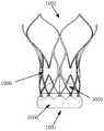
图1是本发明根据一实施例所提供的人工心脏瓣膜假体的结构示意图;1 is a schematic structural diagram of an artificial heart valve prosthesis provided by the present invention according to an embodiment;
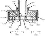
图2是本发明根据一实施例所提供的人工心脏瓣膜假体的局部剖面图;2 is a partial cross-sectional view of an artificial heart valve prosthesis according to an embodiment of the present invention;
图3是本发明根据一实施例所提供的人工心脏瓣膜假体的支架的平面展开示意图;3 is a schematic plan view of a stent for an artificial heart valve prosthesis provided by the present invention according to an embodiment;
图4是图3所示的人工心脏瓣膜假体的支架的接合部处的放大示意图;FIG. 4 is an enlarged schematic view of the joint of the stent of the artificial heart valve prosthesis shown in FIG. 3;
图5是本发明根据一实施例所提供的人工心脏瓣膜假体的接合片的结构示意图;5 is a schematic structural diagram of a joint sheet of an artificial heart valve prosthesis provided according to an embodiment of the present invention;
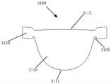
图6是本发明根据一实施例所提供的人工心脏瓣膜假体的小叶的结构示意图;6 is a schematic structural diagram of a leaflet of an artificial heart valve prosthesis according to an embodiment of the present invention;
图7是本发明根据一实施例所述提供的人工心脏瓣膜假体的小叶与接合片的连接关系示意图;FIG. 7 is a schematic diagram of the connection relationship between the leaflets and the joint pieces of the artificial heart valve prosthesis provided according to an embodiment of the present invention;
图8是图7所示的人工心脏瓣膜假体的小叶与接合片连接时的剖面图;FIG. 8 is a cross-sectional view of the artificial heart valve prosthesis shown in FIG. 7 when the leaflets are connected to the coaptation piece;
图9是本发明根据一实施例所提供的人工心脏瓣膜假体的小叶和接合片安装至支架时的示意图;9 is a schematic diagram of the leaflet and the coaptation piece of the prosthetic heart valve prosthesis provided by the present invention according to an embodiment when it is installed on the stent;
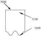
图10是本发明根据一实施例所提供的人工心脏瓣膜假体的裙边的结构示意图。10 is a schematic structural diagram of a skirt of an artificial heart valve prosthesis provided according to an embodiment of the present invention.
具体实施方式Detailed ways
以下通过特定的具体实例说明本发明的实施方式,本领域技术人员可由本说明书所揭露的内容轻易地了解本发明的其他优点与功效。本发明还可以通过另外不同的具体实施方式加以实施或应用,本说明书中的各项细节也可以基于不同观点与应用,在没有背离本发明的精神下进行各种修饰或改变。需要说明的是,本实施例中所提供的图示仅以示意方式说明本发明的基本构想,遂图式中仅显示与本发明中有关的组件而非按照实际实施时的组件数目、形状及尺寸绘制,其实际实施时各组件的型态、数量及比例可为一种随意的改变,且其组件布局型态也可能更为复杂。The embodiments of the present invention are described below through specific specific examples, and those skilled in the art can easily understand other advantages and effects of the present invention from the contents disclosed in this specification. The present invention can also be implemented or applied through other different specific embodiments, and various details in this specification can also be modified or changed based on different viewpoints and applications without departing from the spirit of the present invention. It should be noted that the drawings provided in this embodiment are only to illustrate the basic concept of the present invention in a schematic way, so the drawings only show the components related to the present invention rather than the number, shape and the number of components in actual implementation. For dimension drawing, the type, quantity and proportion of each component can be changed at will in actual implementation, and the component layout may also be more complicated.
另外,以下说明内容的各个实施例分别具有一或多个技术特征,然此并不意味着使用本发明者必需同时实施任一实施例中的所有技术特征,或仅能分开实施不同实施例中的一部或全部技术特征。换句话说,在实施为可能的前提下,本领域技术人员可依据本发明的公开内容,并视设计规范或实作需求,选择性地实施任一实施例中部分或全部的技术特征,或者选择性地实施多个实施例中部分或全部的技术特征的组合,借此增加本发明实施时的弹性。In addition, each embodiment of the following description has one or more technical features, but this does not mean that the person using the present invention must implement all the technical features in any embodiment at the same time, or can only implement different embodiments separately. One or all of the technical features of the . In other words, under the premise of possible implementation, those skilled in the art can selectively implement some or all of the technical features in any embodiment according to the disclosure of the present invention and depending on design specifications or implementation requirements, or The combination of some or all of the technical features in the multiple embodiments is selectively implemented, thereby increasing the flexibility of the implementation of the present invention.
如在本说明书中所使用的,单数形式“一”、“一个”以及“该”包括复数对象,复数形式“多个”包括两个以上的对象,除非内容另外明确指出外。如在本说明书中所使用的,术语“或”通常是以包括“和/或”的含义而进行使用的,除非内容另外明确指出外,以及术语“安装”、“相连”、“连接”应做广义理解,例如,可以是固定连接,也可以是可拆卸连接,或一体地连接。可以是机械连接,也可以是电连接。可以是直接相连,也可以通过中间媒介间接相连,可以是两个元件内部的连通或两个元件的相互作用关系。对于本领域的普通技术人员而言,可以根据具体情况理解上述术语在本发明中的具体含义。As used in this specification, the singular forms "a," "an," and "the" include plural referents, and the plural forms "a plurality" include two or more referents unless the content clearly dictates otherwise. As used in this specification, the term "or" is generally employed in its sense including "and/or" unless the content clearly dictates otherwise, and the terms "installed", "connected", "connected" shall be To be understood in a broad sense, for example, it may be a fixed connection, a detachable connection, or an integral connection. It can be a mechanical connection or an electrical connection. It can be directly connected, or indirectly connected through an intermediate medium, and it can be the internal communication between two elements or the interaction relationship between the two elements. For those of ordinary skill in the art, the specific meanings of the above terms in the present invention can be understood according to specific situations.
如在本说明书中所使用的,“内”是指靠近人工心脏瓣膜假体中心轴的方向,“外”是指远离人工心脏瓣膜假体中心轴的方向。As used in this specification, "inner" refers to the direction near the central axis of the prosthetic heart valve prosthesis, and "outer" refers to the direction away from the central axis of the prosthetic heart valve prosthesis.
为使本发明的目的、优点和特征更加清楚,以下结合附图对本发明作进一步详细说明。需说明的是,附图均采用非常简化的形式且均使用非精准的比例,仅用以方便、明晰地辅助说明本发明实施例的目的。附图中相同或相似的附图标记代表相同或相似的部件。In order to make the objects, advantages and features of the present invention clearer, the present invention will be further described in detail below with reference to the accompanying drawings. It should be noted that, the accompanying drawings are all in a very simplified form and in inaccurate scales, and are only used to facilitate and clearly assist the purpose of explaining the embodiments of the present invention. The same or similar reference numbers in the drawings represent the same or similar parts.
以下描述中提到的瓣叶,除非说明是原生瓣叶,一律指的是人工心脏瓣叶。The leaflets mentioned in the following description, unless stated to be native leaflets, refer to artificial heart valve leaflets.
请参考图1至图6,本发明的一个优选实施例所提供的人工心脏瓣膜假体包括支架1000、接合片2000和瓣叶3000。所述接合片2000和所述瓣叶3000均附着在所述支架1000上,且所述瓣叶3000包括至少两个小叶3100。Referring to FIGS. 1 to 6 , an artificial heart valve prosthesis provided by a preferred embodiment of the present invention includes a
请重点参考图1、图3及图4,所述支架1000是由多根支架杆构成的环形的网格状结构,并具有一流入端1001和一流出端1002。其中,所述流入端1001是指血液的入口端,所述流出端1002是指血液的出口端,所述环形可为圆形、矩形、正多边形等规则形状,也可为其他的不规则形状,为便于理解,本实施例中以圆形为例进行说明,但不应以此作为对本发明的限制。所述支架1000具有沿其周向间隔布置的至少两个接合部1100。每个所述接合部1100上形成有沿所述支架1000的轴向布置的第一窗口1110和第二窗口1120,所述第一窗口1110更靠近所述流出端1002。即,沿所述支架1000的所述流入端1001到所述流出端1002的方向依次布置所述第二窗口1120和所述第一窗口1110,也就是说,所述“轴向”是指将所述人工心脏瓣膜假体植入心脏后与血液流向相平行的方向。Please refer to FIG. 1 , FIG. 3 and FIG. 4 , the
可选地,所述第一窗口1110可为圆形孔,所述第二窗口1120可为沿所述支架1000的轴向延伸的方形孔。在其他的实现方式中,所述第一窗口1110还可以是其他形状,例如方形;所述第二窗口1120也可以是其他形式的长条形孔,例如腰型孔。Optionally, the
请参考图5,所述接合片2000至少部分地覆盖所述接合部1100的外表面,所述接合片2000上设有通孔2100。请再参考图6,至少两个所述小叶3100沿所述支架1000的周向布置。每个所述小叶3100包括主体部3110和设置在所述主体部3110的周向两侧的凸出部3120。所述主体部3110设置在所述支架1000的内侧。所述凸出部3120从所述支架1000的内侧穿过所述第二窗口1120和所述通孔2100后,覆盖在所述接合片2000的至少部分外表面上。所述凸出部3120缝合在所述第一窗口1110处和所述第二窗口1120处,通过将所述凸出部3120缝合在所述第一窗口1110处,达到防止所述瓣叶3000在是使用过程中下滑的目的。优选地,所述接合片2000也缝合在第一窗口1110处,在分散应力的同时,可以进一步防止所述瓣叶3000在是使用过程中的下滑。Referring to FIG. 5 , the engaging
可理解,所述接合片2000的外表面是指所述接合片2000背离所述接合部1100的表面。所述接合片2000缝合在所述第一窗口1110处是指一缝合线穿过所述第一窗口1110以将所述接合片2000缝合在所述接合部1100上。同理,所述凸出部3120缝合在所述第一窗口1110处,是指一缝合线穿过所述第一窗口1110以将所述凸出部3120缝合在所述接合部1100上,以及所述凸出部3120缝合在所述第二窗口1120处是指一缝合线穿过所述第二窗口1120以将所述凸出部3120缝合在所述接合部1100上。不仅于此,本实施例中,所述凸出部3120还可与所述接合片2000缝合,以方便两者的定位,在两者后续在与所述接合部1100的缝合过程中便于保持相对位置的稳定。另外,为使所述凸出部3120顺利地穿过所述第二窗口1120和所述通孔2100,所述通孔2100优选为沿所述支架1000的轴向延伸的长条形孔,且所述通孔2100与所述第二窗口1120对应设置,以使所述第二窗口1120至少部分裸露而未被所述接合片2000覆盖。It can be understood that the outer surface of the
本实施例所提供的人工心脏瓣膜假体利用所述接合片2000分散所述小叶3100与所述支架1000的连接处(即所述第二窗口1120附近)的应力,提高小叶3100的使用寿命。并且,将所述接合片2000和所述凸出部3120中的至少一个缝合在所述第一窗口1110处,能够有效防止所述瓣叶3000在闭合时受到血流压力而出现下滑的情况,改善使用效果。本发明对所述接合片2000的材质没有特别限定,可以是高分子材料,也可以是天然的生物材料。The artificial heart valve prosthesis provided in this embodiment utilizes the
可选地,请继续参考图3和图4,所述接合部1100上还设置有第三窗口1130,所述第三窗口1130位于所述第二窗口1120靠近所述支架1000的所述流入端1001的一侧。所述接合片2000还缝合在所述第三窗口1130处(即一缝合线穿过所述第三窗口1130以将所述接合片2000缝合在所述连接部1100上),以进一步地分散所述小叶3100与所述支架1000的连接处的应力。本实施例中,请参考图5并结合图9,所述接合片2000大致为长方形结构,且在所述支架1000的轴向上,所接合片2000的尺寸与所述接合部1100的尺寸相当,以使所述接合片2000覆盖所述第一窗口1110和所述第三窗口1130。在其他实施例中,所述接合片2000覆盖所述第一窗口1110和所述第三窗口1130中的一个。相比于接合片2000不覆盖所述第一窗口1110和/或所述第三窗口1130,在覆盖的情况下接合片2000与所述第一窗口1110和/或所述第三窗口1130之间的缝合更稳固。Optionally, please continue to refer to FIG. 3 and FIG. 4 , the
请返回参考图2并结合图3,在所述支架1000的周向上,所述第二窗口1120具有侧支柱1121,所述侧支柱1121具有依次首尾连接的内侧面1121a(朝向所述第二窗口内侧的表面)、外表面1121b(朝向所述支架外侧的表面,也是所述接合部的外表面的一部分)、外侧面1121c(背离所述第二窗口一侧的表面)和内表面1121d(朝向所述支架内侧的表面,也是所述接合部的内表面的一部分)。所述接合片2000至少部分覆盖所述侧支柱1121的外表面1121b,并还优选覆盖所述侧支柱1121的外侧面1121c和内表面1121d。Referring back to FIG. 2 and in conjunction with FIG. 3 , in the circumferential direction of the
所述凸出部3120包括依次连接的头部3121、中间部3122和尾部3123。所述头部3121穿设在所述第二窗口1120(即所述头部3121覆盖所述侧支柱1121的内侧面1121a)及所述通孔2100。所述中间部3122沿所述侧支柱1121的所述外表面1121b、所述外侧面1121c至所述内表面1121d的方向延伸,以包覆在所述接合片2000设置于所述侧支柱1121的部分上。所述尾部3123与所述小叶3100的所述主体部3110的一部分重叠设置。如此一来,所述接合片2000设置在所述第二窗口1120的所述侧支柱1121上的部分完全被所述小叶3100包覆,有利于将所述小叶3100与所述支架1000的连接处的应力平均地分摊到整个接合部1100上,避免应力集中,提高所述支架1000的耐久性。此外,由于所述接合片2000覆盖了所述侧支柱的外表面1121b、外侧面1121c和内表面11221d,以隔离所述侧支柱11212和所述凸出部3120,避免了所述侧支柱1121与所述凸出部3120之间产生摩擦,提高小叶3100的寿命。The protruding
进一步地,由于所述凸出部3120的所述尾部3123还与所述主体部3110的一部分重叠设置,因此,可利用一缝合线4000对所述凸出部3120进行包缝。如图2所示,所述包缝是指所述缝合线4000依次穿过所述主体部3110、所述第二窗口1120、所述通孔2100及所述尾部3123之后,再次穿过所述主体部3110。该缝合方式中所述缝合线4000环绕所述侧支柱1121,在直接约束所述支架1000的基础上,还使得所述缝合线4000避免与所述接合部1100接触,消除了所述缝合线4000因与所述接合部1100摩擦而断裂的风险。Further, since the
在采用包缝的方式将所述凸出部3120缝合在所述第二窗口1120处时,为使所述凸出部3120保持平整,优选所述接合片2000的所述通孔2100的宽度大于或等于所述第二窗口1120的宽度。所述“宽度”是指所述通孔2100和所述第二窗口1120在所述支架1000的周向上的尺寸,这样在所述支架1000的周向上,所述通孔2100的边缘在所述第二窗口1120的外侧,或者所述通孔2100的边缘与所述第二窗口1120的边缘重合。When the protruding
本领域技术人员可理解,一个所述人工心脏瓣膜假体中,所述小叶3100的数量、所述接合片2000和所述接合部1100的数量相同,具体根据实际需要确定。例如,利用将所述人工心脏瓣膜假体替代二尖瓣时,所述小叶3100、所述接合片2000和所述接合部1100的数量为两个以上。利用所述人工心脏瓣膜假体替代三尖瓣时,所述小叶3100、所述接合片2000和所述接合部1100的数量为三个以上。通常,在一个所述人工心脏瓣膜假体上,多个所述接合部1100位于同一圆周上。Those skilled in the art can understand that, in one of the artificial heart valve prostheses, the number of the
假定一个所述人工心脏瓣膜假体中包括两个所述小叶3100、两个所述接合片2000,及所述支架1000上具有两个所述接合部1100。下面结合图2、图7至图9介绍该人工心脏瓣膜假体的组装方式。以下描述中的术语“左”、“右”、“上”、“下”等皆是基于图7或图9所示的方位或位置关系,仅是为了便于描述本实施例,而不是指示或暗示所指的装置或元件必须具有特定的方位、以特定的方位构造和操作,因此,不能理解为对本发明的限制。It is assumed that one of the artificial heart valve prostheses includes two of the
以下介绍中,为方便区分,将两个所述小叶3100分别称之为第一小叶3100a和第二小叶3100b,其中所述第一小叶3100a的两个凸出部3120分别为第一左凸出部3120a,第一右凸出部3120b,所述第二小叶3100b的两个凸出部3120分别为第二左凸出部3120c和第二右凸出部3120d。两个所述接合片2000分别第一接合片2000a和第二接合片(图中未示出)。In the following description, for the convenience of distinction, the two
首先,如图7所示,使所述第一小叶3100a的第一右凸出部3120b穿过所述第一接合片2000a的所述通孔2100,以及使所述第二小叶3100b的第二左凸出部3120c穿过所述第一接合片2000a的所述通孔2100。First, as shown in FIG. 7, the first
然后,将所述第一右凸出部3120b向左弯折,再用一缝合线4000将所述第一接合片2000和所述第一右凸出部3120b缝合在一起。同理,将所述第二左凸出部3120c向右弯折,再用一缝合线4000将所述第一接合片2000a和所述第二左凸出部3120c缝合在一起(如图8所示)。Then, the first
之后,按照上面的方法将所述第一小叶3100a的所述第一左凸出部3120a和所述第二小叶3100b的所述第二右凸出部3120d与所述第二接合片连接。Afterwards, the first
接着,将所述第一接合片2000a及所述第一右凸出部3120b和所述第二左凸出部3120c整体地从所述支架1000的内侧穿过一个所述第二窗口1120,之后拉平所述第一接合片2000a、所述第一右凸出部3120b和所述第二凸出部3120c(如图9所示)。以及,将所述第二接合片、所述第一左凸出部和所述第二右凸出部整体地从所述支架的内侧穿过另一个所述第二窗口,之后拉平所述第二接合片、所述第一左凸出部和所述第二右凸出部(图中未示出)。Next, the first
接着,按照图2所示的方式弯折所述接合片2000和所述凸出部3120,以使所述接合片2000覆盖在相应的所述第二窗口1120的两个侧支柱1121上,并使所述凸出部3120分别覆盖在相应的所述接合片2000上。Next, the engaging
接着,利用缝合线将所述接合片2000的上部分缝合在相应的所述第一窗口1110处(图中未示出)。再沿所述支架1000的轴向向下并采用如前所介绍的方式将所述凸出部3120缝合在相应的所述第二窗口1120处。最后将所述接合片2000的下部分缝合在相应的所述第三窗口1130处(图中未示出)。Next, the upper part of the
优选地,在靠近所述支架1000的流入端1001的一侧,所述凸出部3120与所述主体部3110的相接处还设置有卡槽3130,以方便组装时的定位。具体地,在组装所述小叶3100与所述接合片2000时,所述卡槽3130卡设在所述接合片2000的所述通孔2100处。在将所述小叶3100和所述接合片2000安装至所述支架1000上时,所述卡槽3130还卡设在所述第二窗口1120的下边缘上。Preferably, on the side close to the
此外,所述小叶3100的所述主体部3110具有相对设置的固定边3111和自由边3112。所述固定边3111靠近所述支架1000的所述流入端1001,并与所述支架1000连接。所述自由边3112靠近所述支架1000的所述流出端1002,当所述瓣叶3000处于打开状态时,所有所述小叶3100的自由边3112相互分离,当所述瓣叶3000处于闭合状态时,所有所述小叶3000的自由边3112相互贴合。优选地,沿所述支架1000的轴向,所述自由边3112到所述支架1000的流出端1002的端部的距离大于所述小叶3100的所述凸出部3120到所述流出端1002的端部的最小距离,这样设置的目的在于,当所述瓣叶3000处于所述闭合状态时,所述小叶3100的牵拉受力点低于所述支架1000的牵拉受力点,减小所述支架1000的受力,提高支架1000的耐久性。In addition, the
较佳地,所述固定边3111为大致呈V型结构,且V型结构的拐角为圆角。该形状的所述固定边3111一方面减小了所述小叶3100上的应力,提高所述瓣叶3000的耐久性,另一方面减少了所述小叶3100的中部的折痕和波纹,进而减少早期钙化,再一方面还有利于减少材料用量。Preferably, the fixed
进一步地,如图1及图10所示,所述人工心脏瓣膜假体还包括裙边5000,所述裙边5000至少包括内裙边5100,所述内裙边5100设置在所述支架1000的流入端1001的内侧,并可与所述主体部3110的所述固定边3111连接。所述裙边5000还可包括外裙边5200,所述外裙边5200设置在所述支架1000的流入端1001的外侧。所述外裙边5200与所述内裙边5100可为一体式结构。所述外裙边5200远离所述内裙边的边缘呈波浪形,以减少材料的用量。Further, as shown in FIG. 1 and FIG. 10 , the artificial heart valve prosthesis further includes a
需要说明的是,前述实施例中,所述接合片2000并不是必须的结构,在替代性的实施例中,其可以省略。如此,所述小叶3100的所述凸出部3120将直接与所述支架1000的所述接合部1100接触。It should be noted that, in the foregoing embodiments, the
本发明实施例还提供了另一种人工心脏瓣膜假体,该人工心脏瓣膜假体与前述实施例所提供的人工心脏瓣膜假体的区别之处仅在于,所述支架上未形成第一窗口。也就是说,本实施例的人工心脏瓣膜假体包括:支架,所述支架具有沿周向间隔布置的至少两个接合部;所述接合部上形成有第二窗口;接合片,至少部分地覆盖所述接合部的外表面,所述接合片上设置有通孔;以及,沿所述支架的周向布置的至少两个小叶,所述小叶包括主体部和设置在所述主体部的周向两侧的凸出部;所述主体部设置在所述支架的内侧,所述凸出部穿过所述第二窗口和所述通孔,并覆盖在所述接合片的至少部分外表面上;其中,所述凸出部缝合在所述第二窗口处。The embodiment of the present invention also provides another artificial heart valve prosthesis, which differs from the artificial heart valve prosthesis provided by the foregoing embodiments only in that the stent does not have a first window formed on it. . That is, the artificial heart valve prosthesis of the present embodiment includes: a stent having at least two joints spaced apart in the circumferential direction; a second window is formed on the joints; and a joint piece, at least partially Covering the outer surface of the engaging portion, the engaging piece is provided with a through hole; and at least two leaflets arranged along the circumferential direction of the stent, the leaflets include a main body portion and a circumferential direction of the main body portion. The protruding parts on both sides; the main body part is arranged on the inner side of the bracket, the protruding parts pass through the second window and the through hole, and cover at least part of the outer surface of the engaging piece ; wherein, the protruding portion is sewn at the second window.
应理解,所述接合片至少部分地覆盖所述接合部的外表面,同时所述凸出部覆盖所述接合片的至少部分外表面,也即所述接合片的至少一部分位于所述接合部和所述凸出部之间。如此,当所述凸出部缝合在所述第二窗口处时,所述接合片被所述凸出部和所述接合部所夹持而保持固定。It should be understood that the engaging piece at least partially covers the outer surface of the engaging portion, while the protruding portion covers at least part of the outer surface of the engaging piece, that is, at least a portion of the engaging piece is located at the engaging portion and the protrusion. In this way, when the protruding portion is sewn at the second window, the engaging piece is clamped by the protruding portion and the engaging portion to remain fixed.
本实施例所提供的人工心脏瓣膜假体的其他结构请参考前文描述,此处不再赘述。虽然本发明披露如上,但并不局限于此。本领域的技术人员可以对本发明进行各种改动和变型而不脱离本发明的精神和范围。这样,倘若本发明的这些修改和变型属于本发明权利要求及其等同技术的范围之内,则本发明也意图包含这些改动和变型在内。For other structures of the artificial heart valve prosthesis provided in this embodiment, please refer to the foregoing description, which will not be repeated here. Although the present invention is disclosed above, it is not limited thereto. Various modifications and variations can be made in the present invention by those skilled in the art without departing from the spirit and scope of the invention. Thus, provided that these modifications and variations of the present invention fall within the scope of the claims of the present invention and their equivalents, the present invention is also intended to include these modifications and variations.
Claims (16)
Priority Applications (4)
| Application Number | Priority Date | Filing Date | Title |
|---|---|---|---|
| CN202011459644.9ACN114617674B (en) | 2020-12-11 | 2020-12-11 | Artificial heart valve prosthesis |
| US18/256,889US20240016601A1 (en) | 2020-12-11 | 2021-11-04 | Prosthetic heart valve |
| PCT/CN2021/128826WO2022121578A1 (en) | 2020-12-11 | 2021-11-04 | Prosthetic heart valve |
| EP21902285.2AEP4260833A4 (en) | 2020-12-11 | 2021-11-04 | Prosthetic heart valve |
Applications Claiming Priority (1)
| Application Number | Priority Date | Filing Date | Title |
|---|---|---|---|
| CN202011459644.9ACN114617674B (en) | 2020-12-11 | 2020-12-11 | Artificial heart valve prosthesis |
Publications (2)
| Publication Number | Publication Date |
|---|---|
| CN114617674Atrue CN114617674A (en) | 2022-06-14 |
| CN114617674B CN114617674B (en) | 2024-12-06 |
Family
ID=81896094
Family Applications (1)
| Application Number | Title | Priority Date | Filing Date |
|---|---|---|---|
| CN202011459644.9AActiveCN114617674B (en) | 2020-12-11 | 2020-12-11 | Artificial heart valve prosthesis |
Country Status (4)
| Country | Link |
|---|---|
| US (1) | US20240016601A1 (en) |
| EP (1) | EP4260833A4 (en) |
| CN (1) | CN114617674B (en) |
| WO (1) | WO2022121578A1 (en) |
Families Citing this family (2)
| Publication number | Priority date | Publication date | Assignee | Title |
|---|---|---|---|---|
| CN114617674B (en)* | 2020-12-11 | 2024-12-06 | 上海微创心通医疗科技有限公司 | Artificial heart valve prosthesis |
| WO2025122263A1 (en)* | 2023-12-07 | 2025-06-12 | St. Jude Medical, Cardiology Division, Inc. | Methods for reducing leaflet stress |
Citations (6)
| Publication number | Priority date | Publication date | Assignee | Title |
|---|---|---|---|---|
| CN102869319A (en)* | 2010-03-11 | 2013-01-09 | 美敦力公司 | Sinus-engaging fixation member |
| US20180325665A1 (en)* | 2017-05-15 | 2018-11-15 | Edwards Lifesciences Corporation | Devices and methods of commissure formation for prosthetic heart valve |
| US20190053896A1 (en)* | 2017-08-16 | 2019-02-21 | Boston Scientific Scimed, Inc. | Replacement heart valve commissure assembly |
| CN111249037A (en)* | 2010-10-05 | 2020-06-09 | 爱德华兹生命科学公司 | Artificial heart valve |
| CN215425316U (en)* | 2020-12-11 | 2022-01-07 | 上海微创心通医疗科技有限公司 | Artificial heart valve prosthesis |
| WO2022121578A1 (en)* | 2020-12-11 | 2022-06-16 | 上海微创心通医疗科技有限公司 | Prosthetic heart valve |
Family Cites Families (4)
| Publication number | Priority date | Publication date | Assignee | Title |
|---|---|---|---|---|
| US6454799B1 (en)* | 2000-04-06 | 2002-09-24 | Edwards Lifesciences Corporation | Minimally-invasive heart valves and methods of use |
| WO2014179761A1 (en)* | 2013-05-03 | 2014-11-06 | Medtronic Inc. | Medical devices for implanting in a valve and associated methods |
| CN109350307B (en)* | 2018-12-03 | 2023-08-29 | 宁波健世科技股份有限公司 | Transcatheter prosthetic valve replacement system |
| JP7541023B2 (en)* | 2019-03-04 | 2024-08-27 | エドワーズ ライフサイエンシーズ コーポレイション | Commissure attachment for artificial valves |
- 2020
- 2020-12-11CNCN202011459644.9Apatent/CN114617674B/enactiveActive
- 2021
- 2021-11-04WOPCT/CN2021/128826patent/WO2022121578A1/ennot_activeCeased
- 2021-11-04USUS18/256,889patent/US20240016601A1/enactivePending
- 2021-11-04EPEP21902285.2Apatent/EP4260833A4/enactivePending
Patent Citations (6)
| Publication number | Priority date | Publication date | Assignee | Title |
|---|---|---|---|---|
| CN102869319A (en)* | 2010-03-11 | 2013-01-09 | 美敦力公司 | Sinus-engaging fixation member |
| CN111249037A (en)* | 2010-10-05 | 2020-06-09 | 爱德华兹生命科学公司 | Artificial heart valve |
| US20180325665A1 (en)* | 2017-05-15 | 2018-11-15 | Edwards Lifesciences Corporation | Devices and methods of commissure formation for prosthetic heart valve |
| US20190053896A1 (en)* | 2017-08-16 | 2019-02-21 | Boston Scientific Scimed, Inc. | Replacement heart valve commissure assembly |
| CN215425316U (en)* | 2020-12-11 | 2022-01-07 | 上海微创心通医疗科技有限公司 | Artificial heart valve prosthesis |
| WO2022121578A1 (en)* | 2020-12-11 | 2022-06-16 | 上海微创心通医疗科技有限公司 | Prosthetic heart valve |
Also Published As
| Publication number | Publication date |
|---|---|
| EP4260833A4 (en) | 2024-08-28 |
| US20240016601A1 (en) | 2024-01-18 |
| EP4260833A1 (en) | 2023-10-18 |
| CN114617674B (en) | 2024-12-06 |
| WO2022121578A1 (en) | 2022-06-16 |
Similar Documents
| Publication | Publication Date | Title |
|---|---|---|
| US20250064586A1 (en) | Heart valves with increased effective orifice area | |
| US10695169B2 (en) | Heart valve sewing cuff | |
| JP7520034B2 (en) | Artificial Heart Valves | |
| CN111182857B (en) | foldable one-way valve | |
| AU757091B2 (en) | Flexible heart valve | |
| CN109561961B (en) | Artificial valve and artificial valve implantation method | |
| US6558418B2 (en) | Flexible heart valve | |
| CA2499779C (en) | Prosthetic mitral valve | |
| JP4551088B2 (en) | Thin heart valve suture ring | |
| BR112021003462A2 (en) | systems and methods for sizing and implanting prosthetic heart valves | |
| WO2022121578A1 (en) | Prosthetic heart valve | |
| JP2016517751A (en) | Prosthetic valve and related devices, systems, and methods | |
| CN217430265U (en) | Valve prosthesis | |
| CN215425316U (en) | Artificial heart valve prosthesis | |
| CN114681139A (en) | Valve stent and prosthetic valve assembly | |
| CN116196145A (en) | Prosthetic heart valve prosthesis | |
| CN117838394A (en) | Integrated atrioventricular valve |
Legal Events
| Date | Code | Title | Description |
|---|---|---|---|
| PB01 | Publication | ||
| PB01 | Publication | ||
| SE01 | Entry into force of request for substantive examination | ||
| SE01 | Entry into force of request for substantive examination | ||
| GR01 | Patent grant | ||
| GR01 | Patent grant |