CN114614183A - Battery package mounting structure and electric aircraft - Google Patents
Battery package mounting structure and electric aircraftDownload PDFInfo
- Publication number
- CN114614183A CN114614183ACN202210209768.4ACN202210209768ACN114614183ACN 114614183 ACN114614183 ACN 114614183ACN 202210209768 ACN202210209768 ACN 202210209768ACN 114614183 ACN114614183 ACN 114614183A
- Authority
- CN
- China
- Prior art keywords
- battery pack
- mounting
- structure according
- rib
- mounting structure
- Prior art date
- Legal status (The legal status is an assumption and is not a legal conclusion. Google has not performed a legal analysis and makes no representation as to the accuracy of the status listed.)
- Pending
Links
- 238000009434installationMethods0.000claimsabstractdescription29
- 238000003780insertionMethods0.000claimsdescription6
- 230000037431insertionEffects0.000claimsdescription6
- 238000012423maintenanceMethods0.000abstractdescription5
- 238000000034methodMethods0.000abstractdescription4
- 230000008569processEffects0.000abstractdescription3
- 239000002131composite materialSubstances0.000description7
- 229910000838Al alloyInorganic materials0.000description6
- 238000005452bendingMethods0.000description2
- 238000002485combustion reactionMethods0.000description2
- 239000000463materialSubstances0.000description2
- 239000000853adhesiveSubstances0.000description1
- 230000001070adhesive effectEffects0.000description1
- 230000009286beneficial effectEffects0.000description1
- 230000008859changeEffects0.000description1
- 238000013461designMethods0.000description1
- 238000004880explosionMethods0.000description1
- 239000000446fuelSubstances0.000description1
- 238000004519manufacturing processMethods0.000description1
- 238000012986modificationMethods0.000description1
- 230000004048modificationEffects0.000description1
- 230000037361pathwayEffects0.000description1
- 230000002093peripheral effectEffects0.000description1
- 230000008439repair processEffects0.000description1
Images


Classifications
- H—ELECTRICITY
- H01—ELECTRIC ELEMENTS
- H01M—PROCESSES OR MEANS, e.g. BATTERIES, FOR THE DIRECT CONVERSION OF CHEMICAL ENERGY INTO ELECTRICAL ENERGY
- H01M50/00—Constructional details or processes of manufacture of the non-active parts of electrochemical cells other than fuel cells, e.g. hybrid cells
- H01M50/20—Mountings; Secondary casings or frames; Racks, modules or packs; Suspension devices; Shock absorbers; Transport or carrying devices; Holders
- H01M50/244—Secondary casings; Racks; Suspension devices; Carrying devices; Holders characterised by their mounting method
- H—ELECTRICITY
- H01—ELECTRIC ELEMENTS
- H01M—PROCESSES OR MEANS, e.g. BATTERIES, FOR THE DIRECT CONVERSION OF CHEMICAL ENERGY INTO ELECTRICAL ENERGY
- H01M50/00—Constructional details or processes of manufacture of the non-active parts of electrochemical cells other than fuel cells, e.g. hybrid cells
- H01M50/20—Mountings; Secondary casings or frames; Racks, modules or packs; Suspension devices; Shock absorbers; Transport or carrying devices; Holders
- H01M50/249—Mountings; Secondary casings or frames; Racks, modules or packs; Suspension devices; Shock absorbers; Transport or carrying devices; Holders specially adapted for aircraft or vehicles, e.g. cars or trains
- H—ELECTRICITY
- H01—ELECTRIC ELEMENTS
- H01M—PROCESSES OR MEANS, e.g. BATTERIES, FOR THE DIRECT CONVERSION OF CHEMICAL ENERGY INTO ELECTRICAL ENERGY
- H01M50/00—Constructional details or processes of manufacture of the non-active parts of electrochemical cells other than fuel cells, e.g. hybrid cells
- H01M50/20—Mountings; Secondary casings or frames; Racks, modules or packs; Suspension devices; Shock absorbers; Transport or carrying devices; Holders
- H01M50/262—Mountings; Secondary casings or frames; Racks, modules or packs; Suspension devices; Shock absorbers; Transport or carrying devices; Holders with fastening means, e.g. locks
Landscapes
- Chemical & Material Sciences (AREA)
- Chemical Kinetics & Catalysis (AREA)
- Electrochemistry (AREA)
- General Chemical & Material Sciences (AREA)
- Engineering & Computer Science (AREA)
- Aviation & Aerospace Engineering (AREA)
- Battery Mounting, Suspending (AREA)
Abstract
Translated fromChinese
Description
Translated fromChinese技术领域technical field
本申请涉及一种电池包安装结构及包括该电池包安装结构的电动飞行器。The present application relates to a battery pack mounting structure and an electric aircraft including the battery pack mounting structure.
背景技术Background technique
目前,作为一种新型的中短途空中交通工具,电动飞行器在具有安全性高、噪音低、制造成本低、运营成本低等优势的同时实现了接近零排放,因此吸引了包括航空航天企业、汽车行业、运输行业、以及学术界等的广泛关注。At present, as a new type of medium and short-distance air transportation, electric aircraft has the advantages of high safety, low noise, low manufacturing cost, low operating cost, etc., while achieving near-zero emissions, so it has attracted aerospace companies, automobiles, etc. industry, transportation industry, and academia, etc.
电动飞行器是指依靠电动机而不是内燃机驱动的飞行器,使用电动力推进系统代替内燃机动力,从而获得了很多优点和独特品质。例如,电动飞行器具有安全可靠(不会发生爆炸和燃料泄漏)、结构简单、操作使用简便、维修性好/费用低、经济性好等特点,是名符其实的环境友好飞行器。在设计上也有很多优势:总体布局灵活,可采用最佳布局和非常规/创新布局,可设计出具有超常性能的飞行器,满足特殊用途需求等。Electric aircraft are those powered by electric motors rather than internal combustion engines, using an electric propulsion system instead of internal combustion engine power, resulting in a number of advantages and unique qualities. For example, electric aircraft has the characteristics of safety and reliability (no explosion and fuel leakage), simple structure, easy operation and use, good maintainability/low cost, and good economy. It is a veritable environment-friendly aircraft. There are also many advantages in design: the overall layout is flexible, optimal layouts and unconventional/innovative layouts can be adopted, and aircraft with extraordinary performance can be designed to meet the needs of special purposes, etc.
电动飞行器通过电池包提供动力。为了保证电动飞行器能够飞行,提供动力的电池包的重量较重、体积较大。并且,将电池包安装到飞行器上之后,需要进行定期的检修维护。因此,电池包的固定和安装是亟须解决的问题。Electric aircraft are powered by battery packs. In order to ensure that the electric aircraft can fly, the battery pack that provides power is heavier and bulkier. Moreover, after the battery pack is installed on the aircraft, regular maintenance is required. Therefore, the fixing and installation of the battery pack is an urgent problem to be solved.
现有的电动飞行器通常将电池包安装在机身的内部,方便电池包的拆卸和安装。然而这样会导致电池包占用机身内部的空间,降低飞行器的载人或载货的体积。In the existing electric aircraft, the battery pack is usually installed inside the fuselage to facilitate the disassembly and installation of the battery pack. However, this will cause the battery pack to occupy space inside the fuselage and reduce the volume of the aircraft for carrying people or cargo.
发明内容SUMMARY OF THE INVENTION
鉴于上述现有技术的状态而做出本申请。本申请的目的在于提供一种电池包安装结构及电动飞行器,能将电池包可拆卸地固定于电池包安装结构的内部并且在使拆卸过程方便的同时提高了安装精度、更加易于维护。The present application is made in view of the above-mentioned state of the art. The purpose of the present application is to provide a battery pack installation structure and an electric aircraft, which can detachably fix the battery pack inside the battery pack installation structure, improve the installation accuracy and facilitate maintenance while making the disassembly process convenient.
本申请的第一方面提供一种用于电动飞行器的电池包安装结构,其包括:A first aspect of the present application provides a battery pack mounting structure for an electric aircraft, comprising:
电池包;battery pack;
外壳,该外壳收容所述电池包;a casing, the casing accommodates the battery pack;
导轨,在将所述电池包置入所述外壳或者将所述电池包从所述外壳移出时,所述导轨引导并支撑所述电池包;a guide rail that guides and supports the battery pack when the battery pack is placed in or removed from the casing;
多个安装件,所述多个安装件沿着所述导轨的延伸方向排列,与所述导轨连接;以及a plurality of mounting parts arranged along the extending direction of the guide rail and connected to the guide rail; and
一个或多个紧固件,所述电池包通过所述紧固件可拆卸地固定于一个或多个所述安装件。One or more fasteners by which the battery pack is removably secured to one or more of the mounts.
在至少一个实施方式中,所述多个安装件分别设有供所述电池包通过的开口,所述安装件在所述开口处与所述导轨连接,In at least one embodiment, the plurality of mounting members are respectively provided with openings for the battery packs to pass through, and the mounting members are connected with the guide rails at the openings,
所述电池包的远端从所述导轨的近端向所述导轨的远端依次通过所述多个安装件的所述开口,而将所述电池包置入所述外壳中。The distal end of the battery pack passes through the openings of the plurality of mounting members in sequence from the proximal end of the guide rail to the distal end of the guide rail, and the battery pack is inserted into the housing.
在至少一个实施方式中,所述多个安装件包括一个或多个固定安装件,所述紧固件沿着所述电池包的长度方向和/或厚度方向将所述电池包固定于所述固定安装件。In at least one embodiment, the plurality of mounts include one or more fixed mounts, the fasteners securing the battery pack to the battery pack along a length and/or thickness direction of the battery pack Fixed mounts.
在至少一个实施方式中,所述多个固定安装件包括第一固定安装件,所述第一固定安装件位于所述导轨的所述近端侧,所述电池包的所述远端能从所述第一固定安装件的所述开口进入所述外壳的内部,并且能从所述第一固定安装件的所述开口移出,所述紧固件沿着所述长度方向将所述电池包固定于所述第一固定安装件。In at least one embodiment, the plurality of fixed mounts includes a first fixed mount located on the proximal side of the guide rail, the distal end of the battery pack being accessible from the The opening of the first fixed mount enters the interior of the housing and is removable from the opening of the first fixed mount, the fastener attaching the battery pack along the length be fixed to the first fixed mount.
在至少一个实施方式中,在所述第一固定安装件设有第一连接孔,所述第一连接孔在所述长度方向上延伸,供所述紧固件插入。In at least one embodiment, the first fixed mounting member is provided with a first connection hole, and the first connection hole extends in the longitudinal direction for insertion of the fastener.
在至少一个实施方式中,在所述电池包的所述近端设有第一安装孔,所述第一安装孔沿着所述长度方向延伸,供所述紧固件插入。In at least one embodiment, a first mounting hole is provided at the proximal end of the battery pack, and the first mounting hole extends along the length direction for insertion of the fastener.
在至少一个实施方式中,所述多个固定安装件包括第二固定安装件,所述第二固定安装件位于所述导轨的所述远端侧,所述电池包的所述远端进入所述外壳的内部时能够与所述第二固定安装件的所述开口平齐或者超过所述第二固定安装件的所述开口,所述紧固件沿着所述厚度方向将所述电池包固定于所述第二固定安装件。In at least one embodiment, the plurality of fixed mounts includes a second fixed mount located on the distal side of the rail into which the distal end of the battery pack enters. The inside of the casing can be flush with or exceed the opening of the second fixed mounting member, and the fastener attaches the battery pack to the battery pack along the thickness direction. be fixed to the second fixed mount.
在至少一个实施方式中,在所述第二固定安装件设有第二连接孔,所述第二连接孔在所述厚度方向上延伸,供所述紧固件插入。In at least one embodiment, the second fixed mounting member is provided with a second connection hole, and the second connection hole extends in the thickness direction for insertion of the fastener.
在至少一个实施方式中,在所述电池包的所述远端设有第二安装孔,所述第二安装孔沿着所述厚度方向延伸,供所述紧固件插入。In at least one embodiment, a second mounting hole is provided at the distal end of the battery pack, and the second mounting hole extends along the thickness direction for the fastener to be inserted.
在至少一个实施方式中,在所述第二固定安装件上设有挡边,所述挡边阻止所述电池包的所述远端超过所述第二固定安装件的所述开口一定距离。In at least one embodiment, a rib is provided on the second fixed mount, and the rib prevents the distal end of the battery pack from exceeding the opening of the second fixed mount by a certain distance.
在至少一个实施方式中,在所述挡边上设有定位孔,In at least one embodiment, a positioning hole is provided on the baffle,
在所述电池包的所述远端设有定位件,A positioning member is provided at the distal end of the battery pack,
在所述电池包的所述远端进入所述外壳的内部时,所述定位件能够插入所述定位孔,使第二安装孔的轴线和第二连接孔的轴线重合。When the distal end of the battery pack enters the interior of the housing, the positioning member can be inserted into the positioning hole, so that the axis of the second installation hole and the axis of the second connection hole coincide.
在至少一个实施方式中,在所述电池包的近端设有推拉件,以便于将所述电池包置入或者移出所述外壳。In at least one embodiment, a push-pull member is provided at the proximal end of the battery pack to facilitate placing the battery pack in or out of the housing.
在至少一个实施方式中,所述外壳包括在所述电池包的厚度方向上相对的上蒙皮和下蒙皮、以及在所述电池包的宽度方向上相对的前梁和后梁,通过上蒙皮、下蒙皮、前梁和后梁形成腔体,所述腔体的沿着所述电池包的长度方向的两端开口。In at least one embodiment, the casing includes upper and lower skins opposed in the thickness direction of the battery pack, and front and rear beams opposed in the width direction of the battery pack, through the upper skin The skin, the lower skin, the front beam and the rear beam form a cavity, and both ends of the cavity along the length direction of the battery pack are open.
在至少一个实施方式中,在所述下蒙皮上的与所述电池包的远端相对的位置处设有安装口,通过所述安装口对插入第二安装孔和第二连接孔的所述紧固件进行安装和拆卸。In at least one embodiment, an installation opening is provided on the lower skin at a position opposite to the distal end of the battery pack, through which a pair of holes inserted into the second installation hole and the second connection hole is provided. Install and remove the fasteners described above.
在至少一个实施方式中,所述外壳为电动飞行器的机翼、起落架、平尾结构和垂尾结构中的一者或多者的外壳。In at least one embodiment, the housing is a housing for one or more of a wing, landing gear, horizontal tail structure, and vertical tail structure of an electric aircraft.
本申请的第二方面提供一种电动飞行器,其包括机身和位于所述机身两侧的机翼,所述机翼具有上述技术方案中任一项所述的电池包安装结构。A second aspect of the present application provides an electric aircraft, which includes a fuselage and wings located on both sides of the fuselage, and the wings have the battery pack mounting structure described in any one of the above technical solutions.
通过采用上述技术方案,能将电池包可拆卸地固定于电池包安装结构的内部并且在使拆卸过程方便的同时提高了安装精度、更加易于维护。By adopting the above technical solution, the battery pack can be detachably fixed inside the battery pack installation structure, and the installation accuracy is improved while the disassembly process is convenient, and the maintenance is easier.
附图说明Description of drawings
图1为根据本申请的一个实施方式的电池包安装于机翼的内部的轴测图。FIG. 1 is an isometric view of a battery pack installed inside a wing according to an embodiment of the present application.
图2为根据本申请的一个实施方式的电池包从机翼移出的轴测图。2 is an isometric view of a battery pack removed from a wing according to one embodiment of the present application.
图3为根据本申请的一个实施方式的电池包安装结构的爆炸图。FIG. 3 is an exploded view of a battery pack installation structure according to an embodiment of the present application.
图4为根据本申请的一个实施方式的电池包支撑结构和电池包的爆炸图。4 is an exploded view of a battery pack support structure and a battery pack according to one embodiment of the present application.
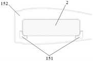
图5为根据本申请的一个实施方式的支撑肋与导轨的连接处的局部放大图。FIG. 5 is a partial enlarged view of a connection between a support rib and a guide rail according to an embodiment of the present application.
图6为根据本申请的一个实施方式的电池包的远端的轴测图。6 is an isometric view of the distal end of a battery pack according to one embodiment of the present application.
图7为根据本申请的一个实施方式的电池包的近端的轴测图。7 is an isometric view of a proximal end of a battery pack according to one embodiment of the present application.
图8为根据本申请的一个实施方式的定位连接肋的轴测图。8 is an isometric view of a positioning connecting rib according to one embodiment of the present application.
图9为根据本申请的一个实施方式的端肋的轴测图。9 is an isometric view of an end rib according to one embodiment of the present application.
图10为根据本申请的一个实施方式的导轨与电池包的连接处的局部放大图。FIG. 10 is a partial enlarged view of the connection between the guide rail and the battery pack according to an embodiment of the present application.
图11为根据本申请的一个实施方式的支撑肋与电池包的连接处的局部放大图。11 is a partial enlarged view of a connection between a support rib and a battery pack according to an embodiment of the present application.
图12为根据本申请的一个实施方式的电池包与定位连接肋的连接处的局部剖视图。12 is a partial cross-sectional view of a connection between a battery pack and a positioning connection rib according to an embodiment of the present application.
图13为根据本申请的一个实施方式的电池包的定位销插入定位连接肋的定位孔的局部剖视图。13 is a partial cross-sectional view of a positioning pin of a battery pack inserted into a positioning hole of a positioning connecting rib according to an embodiment of the present application.
图14为根据本申请的一个实施方式的电池包与端肋的连接处的局部剖视图。14 is a partial cross-sectional view of a connection between a battery pack and an end rib according to an embodiment of the present application.
附图标记说明Description of reference numerals
1 机翼1 wing
11 上蒙皮11 upper skin
12 下蒙皮12 lower skins
13 前梁13 Front beam
14 后梁14 Rear beam
15 电池包支撑结构15 Battery Pack Support Structure
151 导轨151 Rails
152 支撑肋152 Support ribs
153 端肋153 End Ribs
154 定位连接肋154 Positioning the connecting rib
155 螺栓155 Bolts
2 电池包2 battery packs
具体实施方式Detailed ways
下面参照附图描述本申请的示例性实施方式。应当理解,这些具体的说明仅用于示教本领域技术人员如何实施本申请,而不用于穷举本申请的所有可行的方式,也不用于限制本申请的范围。Exemplary embodiments of the present application are described below with reference to the accompanying drawings. It should be understood that these specific descriptions are only used to teach those skilled in the art how to implement the present application, and are not used to exhaust all possible ways of the present application, nor to limit the scope of the present application.
如无特殊说明,在以下的具体实施方式中,“长度方向”指的是电池包2 的长度方向,“宽度方向”指的是电池包2的宽度方向,“厚度方向”指的是电池包2的厚度方向。远端F指的是电池包等的靠近机身的一端,近端N指的是电池包等的远离机身的一端。Unless otherwise specified, in the following specific embodiments, the "length direction" refers to the length direction of the
本申请涉及一种电池包安装结构及电动飞行器(下面,有时简称“飞行器”)。其中,电池包安装结构可以包括电池包2和机翼1的外壳。如图1、图2 所示,可以将电池包2设置于机翼1的内部。这样,电池包2不占用机身内部的空间,从而机身内部的空间可以用于载人或者载货,提高电动飞行器的载重量。The present application relates to a battery pack mounting structure and an electric aircraft (hereinafter, sometimes referred to as "aircraft"). Wherein, the battery pack installation structure may include the
图3是根据本申请的一个实施方式的电池包安装结构/机翼1的爆炸图。机翼1可以包括收容电池包2的外壳以及支撑电池包2的电池包支撑结构15。外壳可以包括上蒙皮11、下蒙皮12、前梁13和后梁14。其中,上蒙皮11和下蒙皮12在电池包2的厚度方向上相对。前梁13和后梁14在电池包2的宽度方向上相对。上蒙皮11、下蒙皮12、前梁13、后梁14在电池包2的长度方向上延伸。电池包支撑结构15固定连接于上蒙皮11、下蒙皮12、前梁13和后梁14。FIG. 3 is an exploded view of the battery pack mounting structure/
具体地,上蒙皮11是机翼1的流线型的上表面。下蒙皮12是机翼1的流线型的下表面。特别地,在下蒙皮12上开有安装口,在安装口上可拆卸地安装下蒙皮口盖121,将该安装口作为机翼1的用于操作电池包支撑结构15、电池包2等内部结构的通路。后述的螺栓155可以经由该通路将电池包2可拆卸地固定于电池包支撑结构15。Specifically, the
上蒙皮11和下蒙皮12保持飞行器的气动外形,直接作用有飞行器的气动载荷并传递飞行器的气动力。上蒙皮11和下蒙皮12可由铝合金、复合材料等材料制造,优选的采用复合材料制造。The
如图3所示,前梁13可以是截面为U字形的长条状的构件,其通过将矩形的长条薄板的两侧的一部分各自向其厚度方向一侧弯折一定角度而形成。前梁13包括两侧弯折的部分(即,前梁连接面13a)和将两个前梁连接面13a连接的前梁支撑面13b。通过两个前梁连接面13a与上蒙皮11和下蒙皮12连接,通过前梁支撑面13b为机翼1提供支撑。As shown in FIG. 3 , the
如图3所示,后梁14可以是截面为U字形的长条状的构件,其通过将矩形的长条薄板的两侧的一部分各自向其厚度方向一侧弯折一定角度而形成。后梁14包括两侧弯折的部分(即,后梁连接面14a)和将两个后梁连接面14a连接的后梁支撑面14b。通过两个后梁连接面14a与上蒙皮11和下蒙皮12连接,通过后梁支撑面14b为机翼1提供支撑。As shown in FIG. 3 , the
作为机翼1的主要承力构件,前梁13和后梁14承受飞行器的机翼1上的主要载荷,可由铝合金、复合材料等材料制造,优选的采用复合材料制造。As the main load-bearing components of the
在本实施方式中,可以通过胶黏剂将上蒙皮11、下蒙皮12、前梁13、后梁14、电池包支撑结构15彼此连接。当电池包2受到载荷时,可以通过电池包支撑结构15将载荷传递到机翼1的前梁13、后梁14、上蒙皮11、下蒙皮12 上。In this embodiment, the
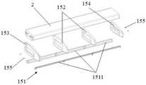
图4是本申请的电池包支撑结构15和电池包2的爆炸图。电池包支撑结构 15可以包括导轨151、作为安装件的支撑肋152、作为第一固定安装件的端肋 153、作为第二固定安装件的定位连接肋154、以及作为紧固件的多个(例如四个)螺栓155。其中,支撑肋152、端肋153、定位连接肋154沿着电池包2 的长度方向排列。导轨151将支撑肋152、端肋153、定位连接肋154连接。两个紧固件155沿着电池包2的长度方向将电池包2的近端固定于端肋153,两个紧固件155沿着电池包2的厚度方向将电池包2的远端固定于定位连接肋154。在一些示例中,这里的电池包2的厚度方向可以与机翼1的厚度方向和上下方向一致。FIG. 4 is an exploded view of the battery
具体地,如图4所示,在电池包2的宽度方向的两侧分别布置有一对导轨 151。在本实施方式中,每条导轨151可以包括三个长度大致相等的导轨子构件1511。Specifically, as shown in FIG. 4 , a pair of
如图4、图5所示,在导轨子构件1511的两端设有突出部1511a。该突出部1511a在电池包2的宽度方向上向与电池包2相反的一侧突出。As shown in FIGS. 4 and 5 ,
此外,如图4、图5所示,在各个导轨子构件1511的近端侧设有凹部1511b。该凹部1511b从导轨子构件1511的内壁面向外壁面凹陷。各个导轨子构件 1511的凹部1511b分别与后述的支撑肋152的第一翻边1522、端肋153的翻边 1532连接。对于凹部1511b,其凹陷的深度和与其连接的翻边的厚度大致相等,其凹陷的宽度和与其连接的翻边的突出长度大致相等。Further, as shown in FIGS. 4 and 5 , a recessed
参照图5,下面对支撑肋152和相邻的导轨子构件1511之间的连接进行说明。在支撑肋152的第一翻边1522所在一侧,使一个导轨子构件1511的凹部 1511b与支撑肋152的第一翻边1522的角部紧密接触,使该导轨子构件1511的突出部1511a与支撑肋152的肋板1521紧密接触。在支撑肋152的没有设置第一翻边1522的一侧,使另一个导轨子构件1511的突出部1511a与支撑肋152的肋板1521紧密接触。由此,将导轨151和支撑肋152组装在一起。此时,导轨子构件1511的没有与第一翻边1522的角部接触的部分的内壁面和第一翻边 1522的角部的内壁面处于同一个平面或曲面。电池包2沿着此平面或曲面推入电池包支撑结构15。Referring to FIG. 5 , the connection between the
端肋153、定位连接肋154和导轨子构件1511之间的连接与上述支撑肋 152和导轨子构件1511之间的连接基本相同,因此省略具体的说明。The connection between the
特别地,在本实施方式中,如图10所示,在电池包2的宽度方向的侧面与导轨151的和该侧面相对的内壁面之间留有间隙。由此,可以确保电池包2 的一部分侧面没有与导轨151的内壁面接触,减少了电池包2和导轨151之间的摩擦力,方便电池包2的推入和拉出。优选的,该间隙可以为例如1.5mm。In particular, in this embodiment, as shown in FIG. 10 , a gap is left between the side surface of the
如图3所示,支撑肋152、端肋153、定位连接肋154均可以对电池包2进行支撑。其中,端肋153和定位连接肋154还可以与螺栓155配合,锁止电池包2。支撑肋152可由铝合金、复合材料等材料制造,优选的采用复合材料制造。端肋153优选的采用铝合金制造。定位连接肋154可由铝合金、复合材料等材料制造,优选的采用铝合金制造。As shown in FIG. 3 , the supporting
参照图5,支撑肋152可以包括肋板1521、第一翻边1522以及第二翻边 1523。在肋板1521的内部开设有供电池包2通过的开口152a,以便电池包2安装。5 , the
如图3和图5所示,肋板1521可以是厚度均匀的薄板。肋板1521的上边缘在整体上是与上蒙皮11的形状相适应的弧形。肋板1521的下边缘在整体上是与下蒙皮12的形状相适应的弧形。肋板1521的上边缘的两端和下边缘的两端向肋板1521的内部凹陷。肋板1521的靠近前梁13所在侧的边缘,即前梁侧边缘平行于前梁支撑面13b,肋板1521的靠近后梁14所在侧的边缘,即后梁侧边缘平行于后梁支撑面14b。肋板1521的前梁侧边缘的长度与前梁支撑面13b 的宽度大致相等。肋板1521的后梁侧边缘的长度与后梁支撑面14b的宽度大致相等。As shown in FIGS. 3 and 5 , the
如图5所示,在上述开口152a的周缘设有第一翻边1522,该第一翻边1522 从开口152a的周缘沿着电池包2的长度方向向远端侧延伸。在上述肋板1521 的上边缘、下边缘、前梁侧边缘以及后梁侧边缘设有第二翻边1523,该第二翻边1523从肋板1521的上边缘、下边缘、前梁侧边缘以及后梁侧边缘沿着电池包2的长度方向向远端侧延伸。As shown in FIG. 5 , a
支撑肋152通过第二翻边1523的上侧翻边与上蒙皮11连接,通过第二翻边1523的下侧翻边与下蒙皮12连接,通过第二翻边1523的前梁13所在侧的翻边与前梁13连接,通过第二翻边1523的后梁14所在侧的翻边与后梁14连接。The
此外,上述两个前梁连接面13a的内壁面分别与支撑肋152的第二翻边1523的上下翻边连接,具体地与第二翻边1523的上下翻边的凹陷处连接。两个前梁连接面13a的外壁面与上蒙皮11、下蒙皮12连接。In addition, the inner wall surfaces of the two front
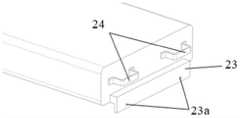
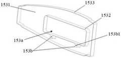
图9是端肋153的轴测图。端肋153可以包括肋板1531、第一翻边1532以及第二翻边1533。FIG. 9 is an isometric view of the
参照图3和图9,肋板1531可以是厚度均匀的薄板。肋板1531的上边缘在整体上是与上蒙皮11的形状相适应的弧形。肋板1531的下边缘在整体上是与下蒙皮12的形状相适应的弧形。肋板1531的上边缘的两端和下边缘的两端向肋板1531的内部凹陷。肋板1531的靠近前梁13所在侧的边缘,即前梁侧边缘平行于前梁支撑面13b,肋板1531的靠近后梁14所在侧的边缘,即后梁侧边缘平行于后梁支撑面14b。肋板1531的前梁侧边缘的长度与前梁支撑面13b的宽度大致相等。肋板1531的后梁侧边缘的长度与后梁支撑面14b的宽度大致相等。3 and 9, the
如图9所示,在肋板1531的内部开设有供电池包2通过的开口153a,以便电池包2安装。在开口153a的下方周缘的两侧分别设有向下方突出的矩形的突起部153b。在突起部153b的内部设有作为第一连接孔的端肋连接孔153b1,供螺栓155旋入。该端肋连接孔153b1可以在电池包2的长度方向上贯穿突起部153b并且内部设有螺纹。As shown in FIG. 9 , an opening 153 a for the
如图9所示,在上述开口153a的周缘设有第一翻边1532,该第一翻边1532 从开口153a的周缘沿着电池包2的长度方向向远端侧延伸。在上述肋板1531 的上边缘、下边缘、前梁侧边缘以及后梁侧边缘设有第二翻边1533,该第二翻边1533从肋板1531的上边缘、下边缘、前梁侧边缘以及后梁侧边缘沿着电池包2的长度方向向远端侧延伸。As shown in FIG. 9 , a
端肋153通过第二翻边1533的上侧翻边与上蒙皮11连接,通过第二翻边 1533的下侧翻边与下蒙皮12连接,通过第二翻边1533的前梁13所在侧的翻边与前梁13连接,通过第二翻边1533的后梁14所在侧的翻边与后梁14连接。The
此外,上述两个前梁连接面13a的内壁面分别与端肋153的第二翻边1533 的上下翻边连接,具体地与第二翻边1533的上下翻边的凹陷处连接。两个前梁连接面13a的外壁面与上蒙皮11、下蒙皮12连接。In addition, the inner wall surfaces of the two front
图8是定位连接肋154的轴测图。定位连接肋154可以包括肋板1541、第一翻边1542以及第二翻边1543。在肋板1541的内部开设有供电池包2通过的开口154a,以便电池包2安装。FIG. 8 is an isometric view of the
参照图3和图8,肋板1541可以是厚度均匀的薄板。肋板1541的上边缘在整体上是与上蒙皮11的形状相适应的弧形。肋板1541的下边缘在整体上是与下蒙皮12的形状相适应的弧形。肋板1541的上边缘的两端和下边缘的两端向肋板1541的内部凹陷。肋板1541的靠近前梁13所在侧的边缘,即前梁侧边缘平行于前梁支撑面13b,肋板1541的靠近后梁14所在侧的边缘,即后梁侧边缘平行于后梁支撑面14b。肋板1541的前梁侧边缘的长度与前梁支撑面13b的宽度大致相等。肋板1541的后梁侧边缘的长度与后梁支撑面14b的宽度大致相等。3 and 8, the
如图8所示,在上述开口154a的周缘设有第一翻边1542,该第一翻边1542 从开口154a的周缘沿着电池包2的长度方向向远端侧延伸。在上述肋板1541 的上边缘、下边缘、前梁侧边缘以及后梁侧边缘设有第二翻边1543,该第二翻边1543从肋板1541的上边缘、下边缘、前梁侧边缘以及后梁侧边缘沿着电池包2的长度方向向远端侧延伸。As shown in FIG. 8 , a
定位连接肋154通过第二翻边1543的上侧翻边与上蒙皮11连接,通过第二翻边1543的下侧翻边与下蒙皮12连接,通过第二翻边1543的前梁13所在侧的翻边与前梁13连接,通过第二翻边1543的后梁14所在侧的翻边与后梁14连接。The
此外,上述两个前梁连接面13a的内壁面分别与定位连接肋154的第二翻边1543的上下翻边连接,具体地与第二翻边1543的上下翻边的凹陷处连接。两个前梁连接面13a的外壁面与上蒙皮11、下蒙皮12连接。In addition, the inner wall surfaces of the two front
此外,在第一翻边1542的下侧翻边上设有两个作为第二连接孔的定位连接肋连接孔1542a,供螺栓155插入。In addition, two positioning connecting
此外,在第一翻边1542的下侧翻边的远端侧边缘设有挡边1544,用于防止电池包2的远端超过定位连接肋154的开口154a一定距离。在挡边1544上设有定位孔1544a,用于保证螺栓155的安装精度。In addition, a
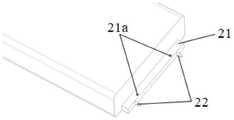
图6是电池包2的远端部分的轴测图。在电池包2的远端部分设有长方体的凸台21,该凸台21沿着电池包2的宽度方向延伸。在凸台21的宽度方向的两侧分别设有供螺栓155旋入的第二安装孔21a,该第二安装孔21a在电池包2 的厚度方向上贯穿凸台21并且在内部设有螺纹。FIG. 6 is an axonometric view of the distal end portion of the
当电池包2推入机翼1内部时,电池包2和支撑肋152、端肋153、定位连接肋154之间存在间隙,位置会有微小的变动,给安装带来麻烦。因此,在本实施方式中,在凸台21的远端侧的面上,在宽度方向的两侧分别设有用于使电池包2定位的定位销22。该定位销22的端头为斜削结构。可以理解,定位销22的斜削结构的直径小于定位连接肋154上的定位孔1544a的直径,从而确保定位销22可以容易地插入定位孔1544a的内部。优选的最大直径差值为5mm。When the
图7是电池包2的近端部分的轴测图。在电池包2的近端部分的面上,在宽度方向的两侧各设计有把手24。该把手24用于提供电池包2推入和拉出的着力点,可以用工具或者人手去操作。FIG. 7 is an axonometric view of the proximal end portion of the
并且,在电池包2的近端的面上设置有翻边23,该翻边23从电池包2的近端的面沿着上下方向向下延伸。在翻边23上设有供螺栓155插入的第一安装孔23a,该第一安装孔23在电池包2的长度方向上贯穿翻边23。In addition, a burring 23 is provided on the surface of the proximal end of the
当电池包2的远端进入机翼1的内部时,定位销22能够插入定位孔1544a (参照图13),使第二安装孔21a的轴线和定位连接肋连接孔1542a的轴线重合。When the distal end of the
如图12所示,螺栓155通过定位连接肋154的定位连接肋连接孔1542a,拧入第二安装孔21a的螺纹上,完成电池包2的远端的固定。As shown in FIG. 12 , the
如图11所示,支撑肋152的第一翻边1522的下侧翻边与电池包2的下壁接触,第一翻边1522的其他翻边与电池包2之间留出间隙。由此,尽可能地减少电池包2和支撑肋152之间的摩擦力,方便电池包2的推入和拉出。优选的间隙为1.5mm。As shown in FIG. 11 , the lower flange of the
如图14所示,螺栓155通过电池包2的第一安装孔23a拧入端肋153的端肋连接孔153b1的螺纹中,完成电池包2的近端的固定。As shown in FIG. 14 , the
以下,对根据本申请的电池包安装结构的部分有益效果进行说明。Hereinafter, some beneficial effects of the battery pack mounting structure according to the present application will be described.
1、连接点少,拆卸方便1. Few connection points, easy to disassemble
通过例如四个螺栓155沿着两个不同的方向上将电池包固定于电池包支撑结构15,满足多方向振动情况下的受力要求。在维护维修时,仅拆卸四个螺栓155,移出电池包2,就可以完成拆卸,使拆卸简单。The battery pack is fixed to the battery
2、受力形式好2. Good force form
电池包2被支撑肋152、端肋153、定位连接肋154包围,当电池包2受力变形时,支撑肋152、端肋153、定位连接肋154对电池包2提供支撑并使电池包2限位,因此受力面积较大,使与电池包2接触的部位所受到的力的大小降低,从而避免了支撑肋152、端肋153、定位连接肋154和电池包2的损坏。The
与此同时,电池包2作为重物装入机翼1内部,当电动飞行器做机动飞行时,会产生的向下的载荷,抵消了一部分机翼1受到的向上的气动载荷,从而降低了机翼1的受载,能有效减轻机翼1的结构重量。At the same time, the
3、安装精度高3. High installation accuracy
当电池包2沿着导轨151推入机翼1的内部后,定位销22的斜削结构插入定位连接肋154的定位孔1544a,从而对电池包2进行定位,使第二安装孔21a 和定位连接肋连接孔1542a对准。由此,使螺栓155能在厚度方向上顺利通过定位连接肋连接孔1542a和第二安装孔21a,从而保证了电池包2的安装精度。After the
4、空间利用率高4. High space utilization
将电池包2安装到作为非装载空间的机翼1的内部,而没有安装到作为装载空间的机身的内部,充分把机身内部的空间释放出来,提高飞行器装载货物或人员的装载能力。The
可以理解,在本申请中,未特别限定部件或构件的数量时,其数量可以是一个或多个,这里的多个是指两个或更多个。对于附图中示出和/或说明书描述了部件或构件的数量为例如两个、三个、四个等的具体数量的情况,该具体数量通常是示例性的而非限制性的,可以将其理解为多个,即两个或更多个。It can be understood that, in the present application, when the number of parts or components is not particularly limited, the number may be one or more, and multiple here refers to two or more. Where the number of parts or components shown in the drawings and/or described in the specification is a specific number such as two, three, four, etc., the specific number is generally exemplary rather than limiting, and the It is understood to mean a plurality, ie two or more.
应当理解,上述实施方式仅是示例性的,不用于限制本申请。本领域技术人员可以在本申请的教导下对上述实施方式做出各种变型和改变,而不脱离本申请的范围。It should be understood that the above-mentioned embodiments are only exemplary, and are not intended to limit the present application. Those skilled in the art can make various modifications and changes to the above-described embodiments under the teachings of the present application, without departing from the scope of the present application.
(i)例如,虽然在本实施方式中,多个紧固件沿着两个方向将电池包固定于电池包支撑结构,但是不限于此。也可以是多个紧固件沿着一个方向将电池包固定于电池包支撑结构。(i) For example, although in the present embodiment, a plurality of fasteners fix the battery pack to the battery pack support structure in two directions, it is not limited to this. A plurality of fasteners may also be used to secure the battery pack to the battery pack support structure in one direction.
(ii)例如,虽然在本实施方式中,电池包安装于飞行器的机翼,但是不限于此。电池包也可以安装到飞行器中其他作为非装载空间的位置,例如,起落架内部、平尾结构内部、垂尾结构内部等。(ii) For example, in the present embodiment, the battery pack is attached to the wing of the aircraft, but it is not limited to this. The battery pack can also be installed in other positions in the aircraft as non-loading spaces, for example, inside the landing gear, inside the horizontal tail structure, inside the vertical tail structure, etc.
(iii)例如,虽然在本实施方式中,电池包的近端设有把手,但是不限定于此。也可以设置其他的推拉结构来实现电池包的安装和拆卸。(iii) For example, in the present embodiment, a handle is provided at the proximal end of the battery pack, but it is not limited to this. Other push-pull structures can also be provided to realize the installation and removal of the battery pack.
(iv)例如,虽然在本实施方式中,在电池包的第二安装孔和端肋的端肋连接孔设有螺纹,但是不限于此。也可以不设置螺纹而采用螺母和螺栓进行对锁安装。(iv) For example, in the present embodiment, the second mounting hole of the battery pack and the end rib connecting hole of the end rib are provided with threads, but the present invention is not limited thereto. It is also possible to use nuts and bolts for locking installation without providing threads.
Claims (16)
Translated fromChinesePriority Applications (1)
| Application Number | Priority Date | Filing Date | Title |
|---|---|---|---|
| CN202210209768.4ACN114614183A (en) | 2022-03-04 | 2022-03-04 | Battery package mounting structure and electric aircraft |
Applications Claiming Priority (1)
| Application Number | Priority Date | Filing Date | Title |
|---|---|---|---|
| CN202210209768.4ACN114614183A (en) | 2022-03-04 | 2022-03-04 | Battery package mounting structure and electric aircraft |
Publications (1)
| Publication Number | Publication Date |
|---|---|
| CN114614183Atrue CN114614183A (en) | 2022-06-10 |
Family
ID=81861720
Family Applications (1)
| Application Number | Title | Priority Date | Filing Date |
|---|---|---|---|
| CN202210209768.4APendingCN114614183A (en) | 2022-03-04 | 2022-03-04 | Battery package mounting structure and electric aircraft |
Country Status (1)
| Country | Link |
|---|---|
| CN (1) | CN114614183A (en) |
Citations (8)
| Publication number | Priority date | Publication date | Assignee | Title |
|---|---|---|---|---|
| WO2016093389A1 (en)* | 2014-12-08 | 2016-06-16 | 한국항공우주연구원 | Solar panel device included in flight vehicle wing, and flight vehicle wing and flight vehicle including same |
| CN205439945U (en)* | 2015-12-29 | 2016-08-10 | 苏州奥杰汽车技术股份有限公司 | Battery package structure convenient to quick installation |
| CN207165660U (en)* | 2017-09-21 | 2018-03-30 | 江苏维科新能源科技有限公司 | A kind of electronic logistic car battery case |
| KR20180041423A (en)* | 2016-10-14 | 2018-04-24 | 한국항공우주연구원 | The battery unit and unmanned aircraft airfoil for spa |
| CN110212129A (en)* | 2019-05-31 | 2019-09-06 | 沈阳无距科技有限公司 | Unmanned plane battery fastening structure and unmanned plane |
| US20200108908A1 (en)* | 2018-10-05 | 2020-04-09 | The Boeing Company | Method and apparatus for attaching a fuselage frame to a wing box |
| CN214647604U (en)* | 2020-11-30 | 2021-11-09 | 北京车和家信息技术有限公司 | Protective structure and vehicle of battery package |
| US20210391627A1 (en)* | 2020-06-16 | 2021-12-16 | Ernest Villanueva | Aircraft energy storage venting system |
- 2022
- 2022-03-04CNCN202210209768.4Apatent/CN114614183A/enactivePending
Patent Citations (8)
| Publication number | Priority date | Publication date | Assignee | Title |
|---|---|---|---|---|
| WO2016093389A1 (en)* | 2014-12-08 | 2016-06-16 | 한국항공우주연구원 | Solar panel device included in flight vehicle wing, and flight vehicle wing and flight vehicle including same |
| CN205439945U (en)* | 2015-12-29 | 2016-08-10 | 苏州奥杰汽车技术股份有限公司 | Battery package structure convenient to quick installation |
| KR20180041423A (en)* | 2016-10-14 | 2018-04-24 | 한국항공우주연구원 | The battery unit and unmanned aircraft airfoil for spa |
| CN207165660U (en)* | 2017-09-21 | 2018-03-30 | 江苏维科新能源科技有限公司 | A kind of electronic logistic car battery case |
| US20200108908A1 (en)* | 2018-10-05 | 2020-04-09 | The Boeing Company | Method and apparatus for attaching a fuselage frame to a wing box |
| CN110212129A (en)* | 2019-05-31 | 2019-09-06 | 沈阳无距科技有限公司 | Unmanned plane battery fastening structure and unmanned plane |
| US20210391627A1 (en)* | 2020-06-16 | 2021-12-16 | Ernest Villanueva | Aircraft energy storage venting system |
| CN214647604U (en)* | 2020-11-30 | 2021-11-09 | 北京车和家信息技术有限公司 | Protective structure and vehicle of battery package |
Similar Documents
| Publication | Publication Date | Title |
|---|---|---|
| CN114889805A (en) | Central wing box structure for electric aircraft and electric aircraft | |
| EP4410639A1 (en) | Vehicle body floor assembly for vehicle and vehicle | |
| US12136720B2 (en) | Battery structural assembly | |
| CN114614183A (en) | Battery package mounting structure and electric aircraft | |
| CN115520370A (en) | Wing system and electric aircraft integrated with power battery module | |
| CN112943564B (en) | Nacelles and wind turbines | |
| US20240021943A1 (en) | Modular airfoil-shaped battery for aircraft | |
| CN220492100U (en) | Batteries and electrical devices | |
| CN220138575U (en) | Battery pack | |
| US10569665B2 (en) | Suspended underfloor power converter | |
| CN222347299U (en) | An eVTOL battery pack installation structure | |
| CN217481714U (en) | Connector, battery box, battery and electrical device | |
| CN115715070A (en) | Computing equipment and computing node | |
| CN221353050U (en) | Box, battery and electrical device | |
| CN114604433A (en) | Battery pack installation structure, electric aircraft and battery pack installation method | |
| CN218086049U (en) | Battery system structure capable of being quickly separated from airplane | |
| CN220553532U (en) | Energy storage box and energy storage device with same | |
| CN219321522U (en) | Battery box body, battery box bracket and battery box mounting structure | |
| CN222355278U (en) | Battery boxes, energy storage devices and electrical equipment | |
| CN222905656U (en) | Subframe and vehicle | |
| CN222247622U (en) | EVTOL aircraft motor arm connection structure | |
| CN221201325U (en) | Frame construction, box, battery and power consumption device of battery | |
| CN221885307U (en) | Battery device and electricity utilization device | |
| CN217507524U (en) | Battery pack lower box body, battery pack and vehicle | |
| CN222529720U (en) | Server box and server |
Legal Events
| Date | Code | Title | Description |
|---|---|---|---|
| PB01 | Publication | ||
| PB01 | Publication | ||
| SE01 | Entry into force of request for substantive examination | ||
| SE01 | Entry into force of request for substantive examination | ||
| RJ01 | Rejection of invention patent application after publication | ||
| RJ01 | Rejection of invention patent application after publication | Application publication date:20220610 |