CN114609746A - Folding camera device - Google Patents
Folding camera deviceDownload PDFInfo
- Publication number
- CN114609746A CN114609746ACN202210343497.1ACN202210343497ACN114609746ACN 114609746 ACN114609746 ACN 114609746ACN 202210343497 ACN202210343497 ACN 202210343497ACN 114609746 ACN114609746 ACN 114609746A
- Authority
- CN
- China
- Prior art keywords
- lens
- height
- camera device
- camera
- folding
- Prior art date
- Legal status (The legal status is an assumption and is not a legal conclusion. Google has not performed a legal analysis and makes no representation as to the accuracy of the status listed.)
- Pending
Links
- 230000003287optical effectEffects0.000claimsabstractdescription90
- 230000006641stabilisationEffects0.000claimsabstractdescription12
- 238000011105stabilizationMethods0.000claimsabstractdescription12
- 230000009977dual effectEffects0.000claimsabstractdescription8
- 230000008901benefitEffects0.000description7
- 230000009467reductionEffects0.000description5
- 239000004033plasticSubstances0.000description4
- 238000010586diagramMethods0.000description3
- 230000007246mechanismEffects0.000description3
- 238000000034methodMethods0.000description3
- 238000005516engineering processMethods0.000description2
- 239000011521glassSubstances0.000description2
- 239000000463materialSubstances0.000description2
- 238000005096rolling processMethods0.000description2
- RYGMFSIKBFXOCR-UHFFFAOYSA-NCopperChemical compound[Cu]RYGMFSIKBFXOCR-UHFFFAOYSA-N0.000description1
- 230000009286beneficial effectEffects0.000description1
- 230000001413cellular effectEffects0.000description1
- 229910052802copperInorganic materials0.000description1
- 239000010949copperSubstances0.000description1
- 230000000694effectsEffects0.000description1
- 238000005265energy consumptionMethods0.000description1
- 238000009434installationMethods0.000description1
- 230000010354integrationEffects0.000description1
- 239000002184metalSubstances0.000description1
- 229910052751metalInorganic materials0.000description1
- 238000012986modificationMethods0.000description1
- 230000004048modificationEffects0.000description1
- 230000008569processEffects0.000description1
- 238000004904shorteningMethods0.000description1
- 229910001220stainless steelInorganic materials0.000description1
- 239000010935stainless steelSubstances0.000description1
- 238000004804windingMethods0.000description1
Images


Classifications
- G—PHYSICS
- G03—PHOTOGRAPHY; CINEMATOGRAPHY; ANALOGOUS TECHNIQUES USING WAVES OTHER THAN OPTICAL WAVES; ELECTROGRAPHY; HOLOGRAPHY
- G03B—APPARATUS OR ARRANGEMENTS FOR TAKING PHOTOGRAPHS OR FOR PROJECTING OR VIEWING THEM; APPARATUS OR ARRANGEMENTS EMPLOYING ANALOGOUS TECHNIQUES USING WAVES OTHER THAN OPTICAL WAVES; ACCESSORIES THEREFOR
- G03B30/00—Camera modules comprising integrated lens units and imaging units, specially adapted for being embedded in other devices, e.g. mobile phones or vehicles
- G—PHYSICS
- G03—PHOTOGRAPHY; CINEMATOGRAPHY; ANALOGOUS TECHNIQUES USING WAVES OTHER THAN OPTICAL WAVES; ELECTROGRAPHY; HOLOGRAPHY
- G03B—APPARATUS OR ARRANGEMENTS FOR TAKING PHOTOGRAPHS OR FOR PROJECTING OR VIEWING THEM; APPARATUS OR ARRANGEMENTS EMPLOYING ANALOGOUS TECHNIQUES USING WAVES OTHER THAN OPTICAL WAVES; ACCESSORIES THEREFOR
- G03B17/00—Details of cameras or camera bodies; Accessories therefor
- G03B17/02—Bodies
- G03B17/17—Bodies with reflectors arranged in beam forming the photographic image, e.g. for reducing dimensions of camera
- G—PHYSICS
- G02—OPTICS
- G02B—OPTICAL ELEMENTS, SYSTEMS OR APPARATUS
- G02B27/00—Optical systems or apparatus not provided for by any of the groups G02B1/00 - G02B26/00, G02B30/00
- G02B27/64—Imaging systems using optical elements for stabilisation of the lateral and angular position of the image
- G—PHYSICS
- G02—OPTICS
- G02B—OPTICAL ELEMENTS, SYSTEMS OR APPARATUS
- G02B13/00—Optical objectives specially designed for the purposes specified below
- G02B13/001—Miniaturised objectives for electronic devices, e.g. portable telephones, webcams, PDAs, small digital cameras
- G02B13/0055—Miniaturised objectives for electronic devices, e.g. portable telephones, webcams, PDAs, small digital cameras employing a special optical element
- G02B13/0065—Miniaturised objectives for electronic devices, e.g. portable telephones, webcams, PDAs, small digital cameras employing a special optical element having a beam-folding prism or mirror
- G—PHYSICS
- G02—OPTICS
- G02B—OPTICAL ELEMENTS, SYSTEMS OR APPARATUS
- G02B27/00—Optical systems or apparatus not provided for by any of the groups G02B1/00 - G02B26/00, G02B30/00
- G02B27/64—Imaging systems using optical elements for stabilisation of the lateral and angular position of the image
- G02B27/646—Imaging systems using optical elements for stabilisation of the lateral and angular position of the image compensating for small deviations, e.g. due to vibration or shake
- G—PHYSICS
- G02—OPTICS
- G02B—OPTICAL ELEMENTS, SYSTEMS OR APPARATUS
- G02B7/00—Mountings, adjusting means, or light-tight connections, for optical elements
- G02B7/02—Mountings, adjusting means, or light-tight connections, for optical elements for lenses
- G—PHYSICS
- G02—OPTICS
- G02B—OPTICAL ELEMENTS, SYSTEMS OR APPARATUS
- G02B7/00—Mountings, adjusting means, or light-tight connections, for optical elements
- G02B7/02—Mountings, adjusting means, or light-tight connections, for optical elements for lenses
- G02B7/021—Mountings, adjusting means, or light-tight connections, for optical elements for lenses for more than one lens
- G—PHYSICS
- G02—OPTICS
- G02B—OPTICAL ELEMENTS, SYSTEMS OR APPARATUS
- G02B7/00—Mountings, adjusting means, or light-tight connections, for optical elements
- G02B7/02—Mountings, adjusting means, or light-tight connections, for optical elements for lenses
- G02B7/04—Mountings, adjusting means, or light-tight connections, for optical elements for lenses with mechanism for focusing or varying magnification
- G02B7/09—Mountings, adjusting means, or light-tight connections, for optical elements for lenses with mechanism for focusing or varying magnification adapted for automatic focusing or varying magnification
- G—PHYSICS
- G03—PHOTOGRAPHY; CINEMATOGRAPHY; ANALOGOUS TECHNIQUES USING WAVES OTHER THAN OPTICAL WAVES; ELECTROGRAPHY; HOLOGRAPHY
- G03B—APPARATUS OR ARRANGEMENTS FOR TAKING PHOTOGRAPHS OR FOR PROJECTING OR VIEWING THEM; APPARATUS OR ARRANGEMENTS EMPLOYING ANALOGOUS TECHNIQUES USING WAVES OTHER THAN OPTICAL WAVES; ACCESSORIES THEREFOR
- G03B13/00—Viewfinders; Focusing aids for cameras; Means for focusing for cameras; Autofocus systems for cameras
- G03B13/32—Means for focusing
- G03B13/34—Power focusing
- G03B13/36—Autofocus systems
- G—PHYSICS
- G03—PHOTOGRAPHY; CINEMATOGRAPHY; ANALOGOUS TECHNIQUES USING WAVES OTHER THAN OPTICAL WAVES; ELECTROGRAPHY; HOLOGRAPHY
- G03B—APPARATUS OR ARRANGEMENTS FOR TAKING PHOTOGRAPHS OR FOR PROJECTING OR VIEWING THEM; APPARATUS OR ARRANGEMENTS EMPLOYING ANALOGOUS TECHNIQUES USING WAVES OTHER THAN OPTICAL WAVES; ACCESSORIES THEREFOR
- G03B17/00—Details of cameras or camera bodies; Accessories therefor
- G03B17/02—Bodies
- G—PHYSICS
- G03—PHOTOGRAPHY; CINEMATOGRAPHY; ANALOGOUS TECHNIQUES USING WAVES OTHER THAN OPTICAL WAVES; ELECTROGRAPHY; HOLOGRAPHY
- G03B—APPARATUS OR ARRANGEMENTS FOR TAKING PHOTOGRAPHS OR FOR PROJECTING OR VIEWING THEM; APPARATUS OR ARRANGEMENTS EMPLOYING ANALOGOUS TECHNIQUES USING WAVES OTHER THAN OPTICAL WAVES; ACCESSORIES THEREFOR
- G03B3/00—Focusing arrangements of general interest for cameras, projectors or printers
- G03B3/10—Power-operated focusing
- G—PHYSICS
- G03—PHOTOGRAPHY; CINEMATOGRAPHY; ANALOGOUS TECHNIQUES USING WAVES OTHER THAN OPTICAL WAVES; ELECTROGRAPHY; HOLOGRAPHY
- G03B—APPARATUS OR ARRANGEMENTS FOR TAKING PHOTOGRAPHS OR FOR PROJECTING OR VIEWING THEM; APPARATUS OR ARRANGEMENTS EMPLOYING ANALOGOUS TECHNIQUES USING WAVES OTHER THAN OPTICAL WAVES; ACCESSORIES THEREFOR
- G03B5/00—Adjustment of optical system relative to image or object surface other than for focusing
- G03B5/02—Lateral adjustment of lens
- H—ELECTRICITY
- H04—ELECTRIC COMMUNICATION TECHNIQUE
- H04N—PICTORIAL COMMUNICATION, e.g. TELEVISION
- H04N23/00—Cameras or camera modules comprising electronic image sensors; Control thereof
- H04N23/45—Cameras or camera modules comprising electronic image sensors; Control thereof for generating image signals from two or more image sensors being of different type or operating in different modes, e.g. with a CMOS sensor for moving images in combination with a charge-coupled device [CCD] for still images
- H—ELECTRICITY
- H04—ELECTRIC COMMUNICATION TECHNIQUE
- H04N—PICTORIAL COMMUNICATION, e.g. TELEVISION
- H04N23/00—Cameras or camera modules comprising electronic image sensors; Control thereof
- H04N23/50—Constructional details
- H04N23/54—Mounting of pick-up tubes, electronic image sensors, deviation or focusing coils
- H—ELECTRICITY
- H04—ELECTRIC COMMUNICATION TECHNIQUE
- H04N—PICTORIAL COMMUNICATION, e.g. TELEVISION
- H04N23/00—Cameras or camera modules comprising electronic image sensors; Control thereof
- H04N23/50—Constructional details
- H04N23/55—Optical parts specially adapted for electronic image sensors; Mounting thereof
- H—ELECTRICITY
- H04—ELECTRIC COMMUNICATION TECHNIQUE
- H04N—PICTORIAL COMMUNICATION, e.g. TELEVISION
- H04N23/00—Cameras or camera modules comprising electronic image sensors; Control thereof
- H04N23/60—Control of cameras or camera modules
- H04N23/67—Focus control based on electronic image sensor signals
- H—ELECTRICITY
- H04—ELECTRIC COMMUNICATION TECHNIQUE
- H04N—PICTORIAL COMMUNICATION, e.g. TELEVISION
- H04N23/00—Cameras or camera modules comprising electronic image sensors; Control thereof
- H04N23/60—Control of cameras or camera modules
- H04N23/68—Control of cameras or camera modules for stable pick-up of the scene, e.g. compensating for camera body vibrations
- H04N23/682—Vibration or motion blur correction
- H04N23/685—Vibration or motion blur correction performed by mechanical compensation
- H04N23/687—Vibration or motion blur correction performed by mechanical compensation by shifting the lens or sensor position
- G—PHYSICS
- G03—PHOTOGRAPHY; CINEMATOGRAPHY; ANALOGOUS TECHNIQUES USING WAVES OTHER THAN OPTICAL WAVES; ELECTROGRAPHY; HOLOGRAPHY
- G03B—APPARATUS OR ARRANGEMENTS FOR TAKING PHOTOGRAPHS OR FOR PROJECTING OR VIEWING THEM; APPARATUS OR ARRANGEMENTS EMPLOYING ANALOGOUS TECHNIQUES USING WAVES OTHER THAN OPTICAL WAVES; ACCESSORIES THEREFOR
- G03B2205/00—Adjustment of optical system relative to image or object surface other than for focusing
- G03B2205/0007—Movement of one or more optical elements for control of motion blur
- G03B2205/0015—Movement of one or more optical elements for control of motion blur by displacing one or more optical elements normal to the optical axis
- G—PHYSICS
- G03—PHOTOGRAPHY; CINEMATOGRAPHY; ANALOGOUS TECHNIQUES USING WAVES OTHER THAN OPTICAL WAVES; ELECTROGRAPHY; HOLOGRAPHY
- G03B—APPARATUS OR ARRANGEMENTS FOR TAKING PHOTOGRAPHS OR FOR PROJECTING OR VIEWING THEM; APPARATUS OR ARRANGEMENTS EMPLOYING ANALOGOUS TECHNIQUES USING WAVES OTHER THAN OPTICAL WAVES; ACCESSORIES THEREFOR
- G03B2205/00—Adjustment of optical system relative to image or object surface other than for focusing
- G03B2205/0053—Driving means for the movement of one or more optical element
- G03B2205/0069—Driving means for the movement of one or more optical element using electromagnetic actuators, e.g. voice coils
- H—ELECTRICITY
- H04—ELECTRIC COMMUNICATION TECHNIQUE
- H04N—PICTORIAL COMMUNICATION, e.g. TELEVISION
- H04N23/00—Cameras or camera modules comprising electronic image sensors; Control thereof
- H04N23/57—Mechanical or electrical details of cameras or camera modules specially adapted for being embedded in other devices
Landscapes
- Physics & Mathematics (AREA)
- General Physics & Mathematics (AREA)
- Optics & Photonics (AREA)
- Engineering & Computer Science (AREA)
- Multimedia (AREA)
- Signal Processing (AREA)
- Human Computer Interaction (AREA)
- Studio Devices (AREA)
- Lens Barrels (AREA)
- Adjustment Of Camera Lenses (AREA)
Abstract
Translated fromChinese
Description
Translated fromChinese本申请为申请号201880014197.0(PCT申请号为PCT/IB2018/060203)、申请日2018年12月17日、发明名称“减少高度容余的折叠摄像装置”的分案申请。This application is a divisional application with application number 201880014197.0 (PCT application number is PCT/IB2018/060203), the filing date is December 17, 2018, and the invention title is "folding camera device with reduced height tolerance".
技术领域technical field
本说明书所披露的实施例大体上关于一种数字摄像装置,并且特别关于薄型的折叠光学摄像装置。Embodiments disclosed in this specification relate generally to a digital camera device, and particularly to a low profile folded optical camera device.
背景技术Background technique
近年来,诸如蜂窝电话(并且特别是智能电话)的移动装置、平板电脑和笔记本电脑已经广为普及了。这些装置中的许多包括一个或两个紧凑型的摄像装置/相机,例如,面向后方的主摄像头(即,设于该装置背面侧上的摄像头,其朝向远离用户的方向并且经常用于休闲摄影)和面向前方的次摄像头(即,设于该装置前面侧上的摄像头,常用于视频会议)。In recent years, mobile devices, such as cellular phones (and in particular smart phones), tablet computers and notebook computers have become widespread. Many of these devices include one or two compact cameras/cameras, eg, a rear-facing main camera (ie, a camera located on the rear side of the device, which faces away from the user and is often used for casual photography ) and a front-facing secondary camera (ie, a camera located on the front side of the device, often used for videoconferencing).
尽管本身已经相对紧凑了,这些摄像装置中的大多数的设计与数字静物摄像装置的传统结构相似,即,其包括设置在图像传感器顶部的透镜组件(或者几个光学元件的系列)。所述透镜组件(也称为“透镜模组”或简单地称为“透镜”)将入射光线进行折射并将其转向以在所述传感器上生成场景的图像。这些摄像装置的大小很大程度上由所述传感器的尺寸和所述光学元件的高度来决定。这些通常通过透镜的焦距(focal length,“f”)及其视场(field of view,FOV)来捆绑在一起的-在一定大小的传感器上产生特定FOV的透镜具有特定的焦距。保持FOV恒定的情况下,所述传感器的尺寸越大,则焦距及其光学元件高度越大。Although inherently relatively compact, the design of most of these cameras is similar to the traditional structure of digital still cameras, ie, they include a lens assembly (or series of several optical elements) placed on top of the image sensor. The lens assembly (also referred to as a "lens module" or simply a "lens") refracts and turns incoming light rays to generate an image of the scene on the sensor. The size of these cameras is largely determined by the size of the sensor and the height of the optics. These are usually tied together by the focal length ("f") of the lens and its field of view (FOV) - a lens that produces a specific FOV on a sensor of a certain size has a specific focal length. Keeping the FOV constant, the larger the size of the sensor, the larger the focal length and the height of its optics.
传统摄像装置的组装过程可以包括处理若干次组件:透镜、传感器板次组件和促动器。所述透镜包括由例如塑料或金属制成的镜筒、和若干(3-7)个由塑料或玻璃制成的透镜元件。所述传感器板次组件可以包括图像传感器、印刷电路板(PCB)和本领域熟知的操作该摄像装置所需的电子元件。使用所述促动器来移动所述透镜以用于光学需要(例如用于对焦(和特别是自动对焦(AF))及/或光学图像稳定(OIS)以及用于对摄像装置的其它部件的机械保护。在现有技术中,沿所述透镜光轴从一侧将所述透镜插入并连接(例如粘接)到所述促动器,而沿所述光轴从相对侧将所述传感器板连接(例如粘接)到所述促动器。The assembly process of a conventional camera device may involve handling several subassemblies: lenses, sensor board subassemblies, and actuators. The lens includes a barrel made of, for example, plastic or metal, and several (3-7) lens elements made of plastic or glass. The sensor board subassembly may include an image sensor, a printed circuit board (PCB), and electronic components well known in the art required to operate the camera device. Use the actuator to move the lens for optical needs (eg for focusing (and in particular autofocus (AF)) and/or optical image stabilization (OIS) and for other components of the camera device Mechanical protection. In the prior art, the lens is inserted and attached (eg, glued) to the actuator from one side along the optical axis of the lens, while the sensor is attached from the opposite side along the optical axis A board is attached (eg glued) to the actuator.
“折叠摄像装置模组”(或简单称为“折叠摄像装置/折叠相机”)是已知的,并且已经并入了各种“主机”装置(例如:智能电话、平板电脑、笔记本电脑、智能TV,等)。在折叠相机中,诸如棱镜或镜子(于此共同称为“反射元件”)的光路折叠元件(OPFE)将到达第一光路或方向的光(例如垂直于智能电话的背侧表面)转向到第二光路或方向(例如平行于所述智能电话的背侧表面)。如果折叠相机是双孔相机的部分,如此会提供穿过透镜组件(例如Tele透镜)的折叠光路。这样的相机/摄像装置在本说明书中称为“折叠透镜双孔相机”或者“具有折叠透镜的双孔相机”。总的来说,所述折叠相机可以被包括在多孔相机中,例如和两个“非折叠”(直立)式相机模组一起包括在三孔相机中,或者在多孔相机中具有多于三个相机。"Folding camera modules" (or simply "folding cameras/folding cameras") are known and have been incorporated into various "host" devices (eg: smartphones, tablets, laptops, smart TV, etc.). In a folding camera, an optical path folding element (OPFE), such as a prism or mirror (collectively referred to herein as a "reflective element"), turns light arriving in a first optical path or direction (eg, perpendicular to the backside surface of the smartphone) to a second optical path or direction. Two optical paths or directions (eg, parallel to the backside surface of the smartphone). If the folded camera is part of a dual aperture camera, this provides a folded light path through the lens assembly (eg Tele lens). Such a camera/camera device is referred to in this specification as a "folded-lens dual-aperture camera" or "a dual-aperture camera with a folded lens". In general, the folding camera may be included in a multi-hole camera, such as a triple-hole camera with two "non-folding" (upright) camera modules, or in a multi-hole camera with more than three camera.
已知在智能电话中使用用于AF和OIS的促动器。通常使用的促动器是基于音圈电机(VCM)技术的。在VCM技术中,使用永久性的(或“固定的”)磁体和线圈来产生驱动力。所述线圈设置在所述固定磁体的磁场附近。当线圈中有驱动电流时,会在所述线圈上产生洛伦兹力(Lorentz force),且反过来在所述磁体上施加相等的反作用力。所述磁体或所述线圈刚性连接到光学元件上以构建驱动组件。所述驱动组件于是由所述磁洛伦兹力来移动。VCM还可以称为“VCM发动机(engine)”,并且包括这样的VCM(或VCM发动机)的促动器可称为“VCM促动器”或简单地称为“促动器”。促动器可以部分或完全地由具有外壳厚度的外壳(有时也称为“壳体”)所围绕。Actuators for AF and OIS are known to be used in smartphones. Commonly used actuators are based on Voice Coil Motor (VCM) technology. In VCM technology, permanent (or "fixed") magnets and coils are used to generate the driving force. The coil is disposed in the vicinity of the magnetic field of the stationary magnet. When there is a drive current in the coil, a Lorentz force is created on the coil, which in turn exerts an equal reaction force on the magnet. The magnet or the coil is rigidly attached to the optical element to construct the drive assembly. The drive assembly is then moved by the magnetic Lorentz force. A VCM may also be referred to as a "VCM engine," and an actuator that includes such a VCM (or VCM engine) may be referred to as a "VCM actuator" or simply an "actuator." The actuator may be partially or completely surrounded by a housing (sometimes also referred to as a "housing") having the thickness of the housing.
在具有移动透镜机构(由促动器/VCM驱动)的折叠相机中,需要至少一个空气间隙来允许移动。所述外壳和增加来保护所述机构的其它可选择的顶部和底部元件或部件(例如板)提高所述促动器的整体高度。折叠相机的小的高度对于使得包括它的主机装置尽可能地薄是很重要的。所述相机的高度很多时候是受限于工业设计情况的。相对地,提高用于透镜、传感器和OPFE的高度可能改善光学特性。In a folding camera with a moving lens mechanism (driven by an actuator/VCM), at least one air gap is required to allow movement. The housing and other optional top and bottom elements or components (eg plates) added to protect the mechanism increase the overall height of the actuator. The small height of the folding camera is important to make the host device that includes it as thin as possible. The height of the camera is often limited by industrial design conditions. Conversely, increasing the height for the lens, sensor and OPFE may improve optical properties.
外壳和其它可选择的顶部和/或底部部件会增加所述折叠相机的高度。该高度因而具有需要减少的“容余(penalty)”。The housing and other optional top and/or bottom components increase the height of the folding camera. This height thus has a "penalty" that needs to be reduced.
在VCMs中,除了磁力之外,已知机械轨道可用于给光学元件产生运动。机械轨道在预期路径中保持所述透镜的移动,如光学需求所要求的。本领域已知的机械轨道的一个例子是“弹簧牵引的轨道”,其中使用一个弹簧或一组弹簧来界定移动方向。包括弹簧牵引的轨道的VCM被称为“弹簧牵引VCM”。例如,美国专利申请第20110235196号披露了在线性弹簧轨道中移动透镜元件来进行对焦。例如,国际专利申请PCT/IB2016/052179号揭露了将弹簧牵引VCM包括和使用在折叠相机中。该专利申请教导了移动透镜元件来进行对焦和OIS和以旋转方式移动光路折叠元件(OPEF)来产生OIS。还有,PCT/IB2016/052179号国际专利申请教导了在折叠促动器的AF+OIS,其中该促动器没有增加折叠相机的高度。In VCMs, in addition to magnetic forces, mechanical tracks are known to be used to impart motion to optical elements. Mechanical tracks keep the lens moving in the desired path, as required by optical requirements. An example of a mechanical track known in the art is a "spring-pulled track" in which a spring or set of springs is used to define the direction of movement. A VCM that includes a spring-pulled track is referred to as a "spring-pull VCM". For example, US Patent Application No. 20110235196 discloses moving a lens element in a linear spring track for focusing. For example, International Patent Application No. PCT/IB2016/052179 discloses the inclusion and use of a spring-pull VCM in a folding camera. This patent application teaches moving the lens element for focus and OIS and moving the optical path folding element (OPEF) in a rotational manner to produce the OIS. Also, International Patent Application No. PCT/IB2016/052179 teaches AF+OIS at a folding actuator, where the actuator does not increase the height of the folding camera.
本领域已知机械轨道的另一个例子是“球引导轨道”,参阅例如美国专利第8810714号。具有球引导轨道,所述透镜通过限制在槽(也称为“狭缝”)里的球体组来使得透镜在所期望的方向里移动。包括球引导轨道的VCM称为“球引导VCM”。球引导VCM相较于弹簧牵引VCM具有若干优势,包括:(1)更低的能量消耗,因为在弹簧牵引VCM中磁力须对抗球引导VCM中不存在的弹簧机械力,及(2)在掉落中更高的可靠性,包括VCM的相机的使用寿命期间可能会发生各种掉落事件。在美国专利第8810714号中的驱动方法设计用于示例性的非折叠透镜,其中透镜光轴直接指向待拍摄的对象,且所述透镜光轴不能用于折叠相机中。Another example of a mechanical track known in the art is a "ball guide track", see eg US Pat. No. 8,810,714. With ball guide tracks, the lens is moved in the desired direction by a set of spheres confined in slots (also called "slits"). A VCM that includes a ball guide track is called a "ball guide VCM". Ball-guided VCMs have several advantages over spring-pull VCMs, including: (1) lower energy consumption because in spring-pull VCMs the magnetic force must oppose the mechanical force of the spring that is not present in ball-guided VCMs, and (2) in the fallout Greater reliability in drops, various drop events may occur during the life of the camera including the VCM. The driving method in US Pat. No. 8,810,714 is designed for an exemplary non-folding lens, where the lens optical axis is directed directly at the object to be photographed, and which cannot be used in a folding camera.
故而,有需要降低折叠相机的高度和长度容余,并且对于线性球引导VCM的结构和设计来说降低折叠相机中的高度和长度的容余都是有好处的。Therefore, there is a need to reduce the height and length allowances in the folded camera, and it would be beneficial for the structure and design of the linear ball guided VCM to reduce the height and length allowances in the folded camera.
发明内容SUMMARY OF THE INVENTION
本说明书中描述的实施例关于具有降低了高度的透镜的促动器(例如VCM设计的)和具有这样的促动器的折叠相机/摄像装置。术语“透镜”可以指的是透镜组件,包括若干光学元件的系列组和收容所述透镜元件的透镜。透镜的特征在于固定有效焦距(fixedeffective focal length,EFL)、光圈(clear aperture)和高度,固定有效焦距和光圈都在国际专利申请第PCT/IB2018/050988号中有界定、并于此整体并入本说明书中,所述高度是沿所述透镜上的最高点和最低点的距离。透镜元件可以由塑料、玻璃和本领域已知的其它材料制成。Embodiments described in this specification relate to actuators with reduced height lenses (eg, of the VCM design) and folding cameras/cameras with such actuators. The term "lens" may refer to a lens assembly comprising a series of optical elements and a lens housing the lens elements. The lens is characterized by a fixed effective focal length (EFL), clear aperture, and height, all of which are defined in International Patent Application No. PCT/IB2018/050988, which is incorporated herein in its entirety In this specification, the height is the distance along the highest point and the lowest point on the lens. The lens elements can be made of plastic, glass, and other materials known in the art.
促动器和折叠相机的所述高度主要由所述透镜的直径(高度)和“容余(penalty)”来决定。在本说明书中,附加于所述透镜直径的任何高度被认为是“容余”。更具体地,容余是上(或顶(top))高度容余和下(或底(bottom))高度容余的和,下方将对“上(upper)”、“下(lower)”和“容余(penalty)”等术语详细描述。The height of the actuator and folding camera is mainly determined by the diameter (height) and "penalty" of the lens. In this specification, any height in addition to the diameter of the lens is considered "tolerance". More specifically, the margin is the sum of the upper (or top) height margin and the lower (or bottom) height margin, below which will be the "upper", "lower" and Terms such as "penalty" are described in detail.
在本发明的各项实施例中,本说明书所描述的具有降低高度的透镜的促动器可以具有外壳,所述外壳设有底部开孔、顶部开孔或底部和顶部开孔。包括这样的促动器的折叠相机具有“降低高度的容余(reduced height penalty)”,高度降低的容余由所述底部开孔、所述顶部开孔、或者所述底部和顶部开孔造成的,所述底部开孔、所述顶部开孔、或者所述底部和顶部开孔允许缩短所述透镜和所述外壳最外面(例如,顶部或底部)表面之间的距离。所述外壳可围绕所述透镜促动器(例如,由环绕所述透镜促动器折叠或弯曲的片体(sheet)制成、或者由若干焊接或胶接在一起的部分制成)。如所提到的,所述外壳具有外壳厚度。术语“外壳厚度”指的是形成所述外壳的材料(例如不锈钢、塑料、铜等)的厚度。如果所述外壳由不同部分制成的,则术语“外壳厚度”指的是每个部分的厚度。In various embodiments of the invention, the actuators with reduced height lenses described in this specification may have housings with bottom openings, top openings, or bottom and top openings. Folding cameras including such actuators have a "reduced height penalty" caused by the bottom opening, the top opening, or the bottom and top openings Yes, the bottom opening, the top opening, or the bottom and top openings allow for a shortening of the distance between the lens and the outermost (eg, top or bottom) surface of the housing. The housing may surround the lens actuator (eg, be made of a sheet that is folded or bent around the lens actuator, or of several parts welded or glued together). As mentioned, the casing has a casing thickness. The term "shell thickness" refers to the thickness of the material (eg, stainless steel, plastic, copper, etc.) from which the shell is formed. If the shell is made of different parts, the term "shell thickness" refers to the thickness of each part.
在本说明书中,光路折叠元件(OPFE)是包括反射板的光学元件,所述OPFE能够将光从一个轴转向到第二轴,所述两个光轴彼此大体垂直,所述反射板相对于所述两个光轴都倾斜45度。In this specification, an optical path folding element (OPFE) is an optical element comprising a reflective plate capable of turning light from one axis to a second axis, the two optical axes being substantially perpendicular to each other, the reflective plate relative to Both optical axes are inclined at 45 degrees.
在本发明的各项实施例中,提供一种折叠相机/摄像装置,包括:定位在OPFE和图像传感器之间的光路中的可移动的透镜和至少部分围绕所述透镜的外壳。其中,所述OPFE将光从第一方向转向到第二方向,并且所述透镜包括平行于所述第二方向的透镜光轴、大体上与所述第一方向对准的透镜高度、第一透镜表面和正对所述第一透镜表面的第二透镜表面,所述第一透镜表面和所述第二透镜表面位于垂直所述第一方向的平面里。所述外壳沿着所述第一方向包括第一外壳部分和第二外壳部分,所述第一外壳部分具有位于所述透镜的第一侧上的第一开孔,所述外壳在所述透镜完全相对的第二侧上没有开孔。其中,所述第一透镜表面沿所述第一方向相对所述第一外壳部分的外表面距离第一空气间隙;所述第二透镜表面沿所述第一方向相对所述第二外壳部分的内表面距离第二空气间隙。其中所述第二外壳部分具有第二外壳厚度,并且其中所述折叠摄像装置/折叠相机具有大体上与所述第一方向对准的摄像装置高度/相机高度,所述摄像装置高度/相机高度大体上等于所述透镜高度、所述第一空气间隙、所述第二空气间隙和所述第二外壳部分厚度的总和。In various embodiments of the present invention, there is provided a foldable camera/camera device comprising: a movable lens positioned in an optical path between an OPFE and an image sensor and a housing at least partially surrounding the lens. wherein the OPFE diverts light from a first direction to a second direction, and the lens includes a lens optical axis parallel to the second direction, a lens height substantially aligned with the first direction, a first A lens surface and a second lens surface facing the first lens surface, the first lens surface and the second lens surface are located in a plane perpendicular to the first direction. The housing includes a first housing portion and a second housing portion along the first direction, the first housing portion having a first aperture on a first side of the lens, the housing on the lens There are no openings on the diametrically opposed second side. Wherein, the first lens surface is opposite to the outer surface of the first housing part along the first direction at a distance from a first air gap; the second lens surface is opposite to the second housing part along the first direction The inner surface is spaced from the second air gap. wherein the second housing portion has a second housing thickness, and wherein the folding camera/camera has a camera height/camera height generally aligned with the first orientation, the camera height/camera height Substantially equal to the sum of the lens height, the first air gap, the second air gap, and the thickness of the second housing portion.
在本发明的各项实施例中,提供一种折叠摄像装置/折叠相机,包括定位在光路折叠元件(OPFE)和图像传感器之间的光路中的可移动的透镜、和至少部分围绕所述透镜的外壳。其中,所述OPFE将光从第一方向转向到第二方向,并且所述透镜包括平行于所述第二方向的透镜光轴、大体上与所述第一方向对准的透镜高度、第一透镜表面和正对所述第一透镜表面的第二透镜表面,所述第一透镜表面和所述第二透镜表面位于垂直所述第一方向的平面里。所述外壳沿着所述第一方向包括第一外壳部分和第二外壳部分,所述第一外壳部分具有位于所述透镜的第一侧上的第一开孔,所述第二外壳部分具有位于正对所述透镜的第二侧上的第二开孔。其中,所述第一透镜表面沿所述第一方向相对所述第一外壳部分的外表面距离第一空气间隙,所述第二透镜表面沿所述第一方向相对所述第二外壳部分的外表面距离第二空气间隙。所述折叠摄像装置/折叠相机具有大体上与所述第一方向对准的摄像装置高度/相机高度,所述摄像装置高度/相机高度大体上等于所述透镜高度、所述第一空气间隙和所述第二空气间隙的总和。In various embodiments of the present invention, there is provided a folding camera/folding camera comprising a movable lens positioned in the optical path between an optical path folding element (OPFE) and an image sensor, and at least partially surrounding the lens shell. wherein the OPFE diverts light from a first direction to a second direction, and the lens includes a lens optical axis parallel to the second direction, a lens height substantially aligned with the first direction, a first A lens surface and a second lens surface facing the first lens surface, the first lens surface and the second lens surface are located in a plane perpendicular to the first direction. The housing includes a first housing portion having a first aperture on a first side of the lens and a second housing portion along the first direction, the second housing portion having A second aperture on the second side facing the lens. Wherein, the first lens surface is opposite to the outer surface of the first housing part along the first direction at a distance from a first air gap, and the second lens surface is opposite to the second housing part along the first direction The outer surface is spaced from the second air gap. The folded camera/folded camera has a camera height/camera height substantially aligned with the first orientation, the camera height/camera height being substantially equal to the lens height, the first air gap, and the sum of the second air gaps.
在如上或如下的折叠摄像装置/折叠相机的某些示例性实施例中,所述第一和第二空气间隙中的每一个可以在10-50μm的范围内。在如上或如下的折叠摄像装置/折叠相机的某些示例性实施例中,所述第一和第二空气间隙中的每一个可以在10-100μm的范围内。在如上或如下的折叠摄像装置/折叠相机的某些示例性实施例中,所述第一和第二空气间隙中的每一个可以在10-150μm的范围内。In certain exemplary embodiments of the folding camera/camera as above or below, each of the first and second air gaps may be in the range of 10-50 μm. In some exemplary embodiments of the folding camera/camera as above or below, each of the first and second air gaps may be in the range of 10-100 μm. In certain exemplary embodiments of the folding camera/camera as above or below, each of the first and second air gaps may be in the range of 10-150 μm.
在本发明的某些示例性实施例中,所述透镜是可移动的,以用于对焦。In some exemplary embodiments of the invention, the lens is movable for focusing.
在本发明的某些示例性实施例中,所述透镜是可移动的,以用于光学图像稳定。In certain exemplary embodiments of the invention, the lens is movable for optical image stabilization.
在本发明的某些示例性实施例中,所述透镜在单一平面中的两个方向上是可移动的,以用于对焦和光学图像稳定,所述单一平面垂直于所述第一方向。In certain exemplary embodiments of the present invention, the lens is movable in two directions in a single plane perpendicular to the first direction for focusing and optical image stabilization.
在本发明的某些示例性实施例中,所述折叠摄像装置/折叠相机具有不超过所述透镜高度多于600μm的高度。在本发明的某些示例性实施例中,所述折叠摄像装置/折叠相机具有不超过所述透镜高度多于400μm的高度。在本发明的某些示例性实施例中,所述折叠摄像装置/折叠相机具有不超过所述透镜高度多于300μm的高度。In certain exemplary embodiments of the present invention, the folding camera/camera has a height that does not exceed the lens height by more than 600 μm. In certain exemplary embodiments of the present invention, the folding camera/camera has a height that does not exceed the lens height by more than 400 μm. In certain exemplary embodiments of the invention, the folding camera/camera has a height that does not exceed the lens height by more than 300 μm.
在本发明的某些示例性实施例中,如上的折叠摄像装置/折叠相机可以和直立式摄像装置/相机一起包括在双摄像装置/相机中。In some exemplary embodiments of the present invention, the foldable camera/camera as above may be included in a dual camera/camera along with the upright camera/camera.
在本发明的示例性实施例中,提供一种折叠摄像装置/折叠相机,包括:在至少一个方向上移动透镜的透镜促动器,包括至少部分围绕所述透镜并具有外壳厚度的外壳,所述透镜具有透镜高度、位于光路折叠元件和图像传感器之间的光路中、并在所述至少一个方向上是可移动的,其中所述折叠摄像装置具有的高度小于所述透镜高度、从所述透镜到所述外壳的第一空气间隙的尺寸、从所述透镜到所述外壳的第二空气间隙的尺寸和所述外壳厚度的两倍的总和。In an exemplary embodiment of the present invention, there is provided a folding camera/camera comprising: a lens actuator that moves a lens in at least one direction, comprising a housing at least partially surrounding the lens and having a housing thickness, whereby The lens has a lens height, is located in the optical path between the optical path folding element and the image sensor, and is movable in the at least one direction, wherein the folded camera has a height less than the lens height, from the The sum of the size of the first air gap from the lens to the housing, the size of the second air gap from the lens to the housing, and twice the thickness of the housing.
在本发明的示例性实施例中,提供一种折叠摄像装置/折叠相机,包括:用于在至少一个方向移动透镜的透镜促动器,所述透镜促动器包括至少部分围绕所述透镜并具有外壳厚度的外壳,所述透镜具有透镜高度、设于光路折叠元件和图像传感器之间的光路中、并在所述至少一个方向是可移动的,其中所述折叠摄像装置/相机具有的高度小于所述透镜高度、从所述透镜到所述外壳的外表面的第一空气间隙的尺寸、从所述透镜到所述外壳的第二空气间隙和所述外壳厚度的总和。In an exemplary embodiment of the present invention, there is provided a folding camera/camera comprising: a lens actuator for moving a lens in at least one direction, the lens actuator comprising at least partially surrounding the lens and A housing having a housing thickness, the lens has a lens height, is positioned in the optical path between the optical path folding element and the image sensor, and is movable in the at least one direction, wherein the folding camera/camera has a height of Less than the sum of the height of the lens, the size of the first air gap from the lens to the outer surface of the housing, the second air gap from the lens to the housing, and the thickness of the housing.
在本发明的各项实施例中,提供一种用于移动透镜的透镜促动器,所述透镜具有平行于第二方向的透镜光轴和大体上与第一方向对准的透镜高度,所述第二方向大体上垂直于所述第一方向,所述促动器包括:至少部分围绕所述透镜的外壳,所述外壳沿所述第一方向包括具有位于所述透镜第一侧上的第一开孔的第一外壳部分和第二外壳部分,所述外壳在所述透镜的完全相对的第二侧上没有开孔,其中第一透镜表面沿所述第一方向相对所述第一外壳部分的外表面距离第一空气间隙,其中第二透镜表面沿所述第一方向相对所述第二外壳部分的内表面距离第二空气间隙,其中所述第二外壳部分具有第二外壳厚度,并且其中所述折叠摄像装置具有大体上与所述第一方向对准的摄像装置高度,所述摄像装置高度大体上等于所述透镜高度、所述第一空气间隙、所述第二空气间隙和所述第二外壳部分厚度的总和。In various embodiments of the present invention, there is provided a lens actuator for moving a lens having a lens optical axis parallel to a second direction and a lens height generally aligned with the first direction, so that The second direction is substantially perpendicular to the first direction, the actuator includes a housing at least partially surrounding the lens, the housing including along the first direction a a first apertured first housing portion and a second housing portion, the housing having no apertures on diametrically opposed second sides of the lens, wherein the first lens surface is opposite the first lens along the first direction an outer surface of the housing portion is spaced from a first air gap, wherein the second lens surface is spaced from an inner surface of the second housing portion along the first direction by a second air gap, wherein the second housing portion has a second housing thickness , and wherein the folded camera has a camera height substantially aligned with the first direction, the camera height being substantially equal to the lens height, the first air gap, the second air gap and the sum of the thickness of the second shell portion.
在本发明的各项实施例中,提供一种用于移动透镜的透镜促动器,所述透镜具有平行于第二方向的透镜光轴和大体上与第一方向对准的透镜高度,所述第二方向大体上垂直于所述第一方向,所述促动器包括:在至少部分里围绕所述透镜的外壳,所述外壳沿所述第一方向包括第一外壳部分和第二外壳部分,所述第一外壳部分具有位于所述透镜第一侧上的第一开孔,所述第二外壳部在所述透镜的完全相对的第二侧上设有第二开孔,其中第一透镜表面沿所述第一方向相对所述第一外壳部分的外表面距离第一空气间隙,其中第二透镜表面沿所述第一方向相对所述第二外壳部分的外表面距离第二空气间隙,并且其中所述折叠摄像装置具有大体上与所述第一方向对准的摄像装置高度,所述摄像装置高度大体上等于所述透镜高度、所述第一空气间隙和所述第二空气间隙的总和。In various embodiments of the present invention, there is provided a lens actuator for moving a lens having a lens optical axis parallel to a second direction and a lens height generally aligned with the first direction, so that The second direction is substantially perpendicular to the first direction, the actuator includes a housing at least partially surrounding the lens, the housing including a first housing portion and a second housing along the first direction part, the first housing part has a first opening on a first side of the lens, the second housing part has a second opening on a second diametrically opposite side of the lens, wherein the first A lens surface is a first air gap along the first direction relative to an outer surface of the first housing portion, wherein a second lens surface is a second air gap relative to an outer surface of the second housing portion along the first direction a gap, and wherein the folded camera has a camera height substantially aligned with the first direction, the camera height being substantially equal to the lens height, the first air gap, and the second air The sum of the gaps.
在如上或如下的促动器的某些示例性实施例中,所述第一和第二空气间隙中的每一个可以在10-50μm的范围内。在如上或如下的促动器的某些示例性实施例中,所述第一和第二空气间隙中的每一个可以在10-100μm的范围内。在如上或如下的促动器的某些示例性实施例中,所述第一和第二空气间隙中的每一个可以在10-150μm的范围内。In certain exemplary embodiments of the actuator as above or below, each of the first and second air gaps may be in the range of 10-50 μm. In certain exemplary embodiments of the actuator as above or below, each of the first and second air gaps may be in the range of 10-100 μm. In certain exemplary embodiments of the actuator as above or below, each of the first and second air gaps may be in the range of 10-150 μm.
在本发明的某些示例性实施例中,所述透镜是可移动的,以用于对焦。In some exemplary embodiments of the invention, the lens is movable for focusing.
在本发明的某些示例性实施例中,所述透镜是可移动的,以用于光学图像稳定。In certain exemplary embodiments of the invention, the lens is movable for optical image stabilization.
在本发明的某些示例性实施例中,所述透镜在单一平面中的两个方向上是可移动的,以用于对焦和光学图像稳定,所述单一平面垂直于所述第一方向。In certain exemplary embodiments of the present invention, the lens is movable in two directions in a single plane perpendicular to the first direction for focusing and optical image stabilization.
在本发明的某些示例性实施例中,如上或如下的促动器具有不超过所述透镜高度多于600μm的高度。在本发明的某些示例性实施例中,如上或如下的促动器具有不超过所述透镜高度多于400μm的高度。在本发明的某些示例性实施例中,如上或如下的促动器具有不超过所述透镜高度多于300μm的高度。In certain exemplary embodiments of the invention, the actuators as above or below have a height that does not exceed the height of the lens by more than 600 μm. In certain exemplary embodiments of the present invention, the actuators as above or below have a height that does not exceed the height of the lens by more than 400 μm. In certain exemplary embodiments of the invention, the actuators as above or below have a height that does not exceed the height of the lens by more than 300 μm.
在本发明的各项实施例中,提供一种折叠摄像装置/相机,包括:具有透镜高度的透镜,所述透镜设于光路折叠元件和图像传感器之间的光路中、并且至少在一个方向上是可移动的,其中所述折叠摄像装置具有不超过所述透镜高度多于500μm的高度。In various embodiments of the present invention, there is provided a folding camera/camera comprising: a lens having a lens height, the lens being disposed in the optical path between the optical path folding element and the image sensor and in at least one direction is movable, wherein the folded camera device has a height that does not exceed the height of the lens by more than 500 μm.
在本发明的示例性实施例中,如上的所述折叠摄像装置/相机具有不超过所述透镜高度多于400μm的高度。In an exemplary embodiment of the present invention, the folded camera/camera as above has a height that does not exceed the lens height by more than 400 μm.
在本发明的示例性实施例中,如上的所述折叠摄像装置/相机具有不超过所述透镜高度多于250μm的高度。In an exemplary embodiment of the present invention, the folded camera/camera as above has a height that does not exceed the lens height by more than 250 μm.
在本发明的示例性实施例中,如上的所述折叠摄像装置/相机和直立式摄像装置/相机一起被包括在双摄像装置/相机里。In an exemplary embodiment of the present invention, the foldable camera/camera and the upright camera/camera as described above are included together in a dual camera/camera.
在本发明的示例性实施例中,提供一种促动器,用于驱动具有用于AF和光学图像稳定OIS的透镜光轴,所述促动器包括:静止次组件,所述静止次组件包括具有OIS线圈平面的OIS线圈和具有AF线圈平面的AF线圈;以及透镜驱动次组件,所述透镜驱动次组件相对所述静止次组件是可移动的,并且包括固持所述透镜的透镜固持件;其中,所述OIS线圈平面垂直于所述AF线圈平面,并且其中所述透镜光轴位于所述OIS线圈平面和所述AF线圈平面之间。In an exemplary embodiment of the present invention, there is provided an actuator for driving an optical axis of a lens with OIS for AF and optical image stabilization, the actuator comprising: a stationary subassembly, the stationary subassembly including an OIS coil having an OIS coil plane and an AF coil having an AF coil plane; and a lens drive subassembly movable relative to the stationary subassembly and including a lens holder holding the lens ; wherein the OIS coil plane is perpendicular to the AF coil plane, and wherein the lens optical axis is located between the OIS coil plane and the AF coil plane.
在本发明的示例性实施例中,所述静止次组件进一步包括复数个上部步进轭,其中所述透镜驱动次组件进一步包括连接到所述复数个上部步进轭的复数个步进磁体,并且其中所述复数个上部步进轭和所述复数个步进磁体可操作来产生在垂直于所述透镜光轴的方向上的步进力,以实现步进。In an exemplary embodiment of the present invention, the stationary subassembly further includes a plurality of upper stepping yokes, wherein the lens driving subassembly further includes a plurality of stepping magnets connected to the plurality of upper stepping yokes, And wherein the plurality of upper stepping yokes and the plurality of stepping magnets are operable to generate a stepping force in a direction perpendicular to the optical axis of the lens to effect stepping.
在本发明的示例性实施例中,如上或如下的促动器进一步包括用于AF和OIS的中间驱动次组件,其设于所述静止次组件和所述透镜顶部驱动次组件之间。In an exemplary embodiment of the present invention, the actuator as above or below further comprises an intermediate drive subassembly for AF and OIS disposed between the stationary subassembly and the lens top drive subassembly.
在本发明的示例性实施例中,所述静止次组件进一步包括OIS霍尔传感器棒,其与所述步进磁体中的一个一起执行位置感测。In an exemplary embodiment of the present invention, the stationary subassembly further includes an OIS Hall sensor bar that performs position sensing in conjunction with one of the stepping magnets.
在本发明的示例性实施例中,所述复数个步进轭中的一些轭位于第一表面上,其中所述复数个步进轭中的其它轭位于第二表面上,并且其中所述第一表面和所述第二表面是平行的。In an exemplary embodiment of the invention, some of the plurality of stepping yokes are located on a first surface, wherein other yokes of the plurality of stepping yokes are located on a second surface, and wherein the first One surface and the second surface are parallel.
在本发明的示例性实施例中,如上的促动器包括在折叠摄像装置/相机中。In an exemplary embodiment of the present invention, an actuator as above is included in a folding camera/camera.
在本发明的各项实施例中,提供一种折叠摄像装置/相机,包括:具有透镜光轴的透镜;用于将光从第一方向转向到第二方向的光路折叠元件,所述第二方向大体上与所述透镜光轴对准;图像传感器;以及用于驱动所述透镜以自动对焦(AF)和光学图像稳定(OIS)的促动器,所述促动器包括AF音圈电机(VCM),所述AF VCM包括位于AF平面里的AF线圈和OIS VCM,所述AF线圈可操作来在AF方向上移动所述透镜,所述OIS音圈电机包括位于OIS平面里的OIS线圈、并可操作来在OIS方向上移动所述透镜,其中所述AF平面和所述OIS平面彼此垂直,并且其中所述两个VCMs设置在由所述第一方向和所述第二方向界定的平面的相对侧上。In various embodiments of the present invention, there is provided a folding camera/camera comprising: a lens having an optical axis of the lens; an optical path folding element for diverting light from a first direction to a second direction, the second an orientation substantially aligned with the lens optical axis; an image sensor; and an actuator for driving the lens for autofocus (AF) and optical image stabilization (OIS), the actuator including an AF voice coil motor (VCM), the AF VCM includes an AF coil in the AF plane and an OIS VCM, the AF coil is operable to move the lens in the AF direction, the OIS voice coil motor includes an OIS coil in the OIS plane , and is operable to move the lens in an OIS direction, wherein the AF plane and the OIS plane are perpendicular to each other, and wherein the two VCMs are disposed in a direction defined by the first direction and the second direction on the opposite side of the plane.
附图说明Description of drawings
本说明书中所披露的非限制性实施例可参阅以下说明书附图来进行描述。在不同图示中等同的结构、元件或部件通常以相同数字进行标注。所述图示和说明书旨在阐明和澄清本发明的实施例,而不应被认为是以任何方式对本发明进行限制。在所述图示中:The non-limiting embodiments disclosed in this specification can be described with reference to the accompanying drawings in the following specification. Identical structures, elements or components in different figures are generally labeled with the same numerals. The drawings and description are intended to illustrate and clarify embodiments of the invention and should not be construed to limit the invention in any way. In the illustration:
图1A所示的是本发明折叠相机的实施例;Figure 1A shows an embodiment of the folding camera of the present invention;
图1B所示的是图1A所示的折叠相机沿线A-A和B-B截取的截面;Figure 1B shows a cross section of the folding camera shown in Figure 1A taken along lines A-A and B-B;
图1C所示的是本发明折叠相机的另一实施例;Figure 1C shows another embodiment of the folding camera of the present invention;
图1D所示的是沿图1C中B’-B’线截取的折叠相机的侧面;Figure 1D shows a side view of the folded camera taken along the line B'-B' in Figure 1C;
图2A所示的是本发明折叠相机的各元件;Figure 2A shows the components of the folding camera of the present invention;
图2B所示的是本发明具有底部开孔的降低高度的折叠透镜促动器的实施例的俯视立体示意图;FIG. 2B is a schematic top perspective view of an embodiment of the reduced-height folded lens actuator with a bottom opening of the present invention;
图2C所示的是图2B的没有设置上外壳的促动器实施例的俯视立体示意图;FIG. 2C is a schematic top perspective view of the embodiment of the actuator of FIG. 2B without the upper casing;
图2D所示的是图2B的促动器实施例的仰视立体分解示意图;Figure 2D shows a bottom perspective exploded schematic view of the actuator embodiment of Figure 2B;
图2E所示的是图2B的促动器实施例沿C-C和D-D部分之间的部分的前截面示意图;Figure 2E shows a schematic front cross-sectional view of the actuator embodiment of Figure 2B along the portion between C-C and D-D;
图2F所示的是包括图2B-2E中的透镜促动器的降低高度的折叠相机实施例;Illustrated in FIG. 2F is a reduced height folding camera embodiment including the lens actuators of FIGS. 2B-2E;
图2G所示的是沿图2F的折叠相机实施例的D’-D’线截取的侧面;Shown in Figure 2G is a side view taken along the line D'-D' of the folding camera embodiment of Figure 2F;
图3A所示的是本发明具有顶部开孔的降低高度的折叠透镜促动器实施例的俯视立体示意图;FIG. 3A is a schematic top perspective view of an embodiment of a reduced-height folded lens actuator with a top opening of the present invention;
图3B所示的是图3A的促动器实施例没有设置上外壳的俯视立体示意图;Fig. 3B shows a top perspective schematic view of the embodiment of the actuator of Fig. 3A without an upper casing;
图3C所示的是图3A的促动器实施例的仰视立体示意图;Figure 3C shows a bottom perspective schematic view of the actuator embodiment of Figure 3A;
图3D所示的是图3B的促动器实施例的仰视立体示意图;Figure 3D shows a bottom perspective schematic view of the actuator embodiment of Figure 3B;
图3E所示的是图3A-3D的促动器实施例沿图3A中的A-A和B-B部分之间的部分的前视截面示意图;Figure 3E shows a schematic front cross-sectional view of the actuator embodiment of Figures 3A-3D along the portion between A-A and B-B in Figure 3A;
图4A所示的是具有顶部开孔和底部开孔的降低高度的折叠透镜促动器实施例的俯视立体示意图;Figure 4A is a schematic top perspective view of an embodiment of a reduced height folded lens actuator having top openings and bottom openings;
图4B所示的是图4A的具有分离的上外壳的促动器实施例的仰视立体示意图;Figure 4B shows a schematic bottom perspective view of the actuator embodiment with a separate upper housing of Figure 4A;
图4C所示的是图4A的具有顶部开孔和底部开孔的促动器实施例的仰视立体示意图;Figure 4C shows a bottom perspective schematic view of the actuator embodiment with top openings and bottom openings of Figure 4A;
图5A所示的是图4A-C的降低高度的折叠透镜促动器的立体分解图;Figure 5A shows an exploded perspective view of the reduced height folding lens actuator of Figures 4A-C;
图5B所示的是图4A-C的降低高度的折叠透镜促动器的另一视角的立体分解示意图;Figure 5B is a schematic exploded perspective view of the reduced height folding lens actuator of Figures 4A-C from another perspective;
图6所示的是本发明降低高度的折叠透镜促动器中的电子次组件的立体分解示意图;FIG. 6 is a perspective exploded schematic view of the electronic sub-assembly in the reduced-height folding lens actuator of the present invention;
图7所示的是本发明降低高度的折叠透镜促动器中的基座次组件的立体分解示意图;FIG. 7 is a perspective exploded schematic view of the base subassembly in the reduced-height folding lens actuator of the present invention;
图8所示的是本发明降低高度的折叠透镜促动器中的透镜次组件的立体分解示意图;FIG. 8 is a perspective exploded schematic view of the lens sub-assembly in the reduced-height folded lens actuator of the present invention;
图9所示的是本发明降低高度的透镜促动器中的OIS/AF板次组件的立体分解示意图;FIG. 9 is a perspective exploded schematic view of the OIS/AF board sub-assembly in the height-reducing lens actuator of the present invention;
图10A所示的是根据本发明某些方面的折叠相机透镜次组件的实施例及其各部分的立体分解示意图;10A is a schematic exploded perspective view of an embodiment of a folded camera lens subassembly and its various parts according to certain aspects of the present invention;
图10B所示的是本发明AF和OIS线圈相对于透镜光轴的定位的示意图;10B is a schematic diagram of the positioning of the AF and OIS coils of the present invention relative to the optical axis of the lens;
图10C所示的是本发明AF和OIS线圈相对于透镜光轴的定位的另一示意图;10C is another schematic diagram of the positioning of the AF and OIS coils of the present invention relative to the optical axis of the lens;
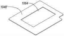
图10D所示的是图10A的透镜次组件中具有增加的顶部开孔的外壳的示意图;Figure 10D is a schematic view of the housing with the added top opening in the lens subassembly of Figure 10A;
图10E所示的是图10A的透镜次组件中具有增加的底部开孔的下部板体的示意图;Fig. 10E is a schematic view of the lower plate body with the increased bottom opening in the lens subassembly of Fig. 10A;
图11A和图11B所示的是所述透镜次组件中的第一VCM促动器的不同视角的立体分解示意图;11A and 11B are exploded perspective views of the first VCM actuator in the lens subassembly from different viewing angles;
图11C和图11D所示的分别是中间支架中的轨道和基座中的轨道的立体示意图;11C and 11D are schematic perspective views of the track in the intermediate bracket and the track in the base, respectively;
图12A和图12B所示的是所述透镜次组件中的第二VCM促动器的不同视角的立体分解示意图;12A and 12B are exploded perspective views of the second VCM actuator in the lens subassembly from different viewing angles;
图12C和图12D所示的分别是中间支架中的轨道和基座中的轨道的立体示意图;Figures 12C and 12D are schematic perspective views of the rails in the intermediate bracket and the rails in the base, respectively;
图13A和图13B所示的与驱动相关的透镜次组件的部件的示意图;Figures 13A and 13B are schematic diagrams of components of the lens subassembly associated with drive;
图14A和图14B所示的分别是顶部驱动次组件的立体分解示意图和组装后的立体示意图;14A and 14B are respectively an exploded perspective view and an assembled perspective view of the top drive subassembly;
图14C和图14D所示的分别是沿图14A和图14B的顶部驱动次组件和棱镜的光轴截取的两个不同实施例的截面示意图;Figures 14C and 14D are schematic cross-sectional views of two different embodiments taken along the optical axis of the top drive subassembly and prism of Figures 14A and 14B, respectively;
图15所示的是包括直立式相机和具有如上和如下所公开的折叠相机的双相机的实施例的立体示意图。Shown in Figure 15 is a schematic perspective view of an embodiment including an upright camera and a dual camera with a foldable camera as disclosed above and below.
具体实施方式Detailed ways
图1A所示为本发明折叠相机/折叠摄像装置100的实施例。折叠相机100包括载有透镜104的透镜促动器102、OPFE(例如,棱镜、镜子等)106和图像传感器108。相机100可以用来给拍摄对象或场景110拍摄。在一个实例中,沿着第一方向112(也称为“入口光轴(entrance optical axis)”)来自所述对象或场景110的光进入OPFE 106、被转向到第二方向114(也称为“透镜光轴”)、进入透镜促动器102、并且然后到达图像传感器108。透镜104可以包括若干透镜元件,这些透镜元件固定在一个镜筒(lens barrel)中或者在多个镜筒中。透镜104可具有固定焦距或变化(可变的)的焦距(“变焦距镜头”)。透镜104可以出于例如对焦(或自动对焦-AF)或光学图像稳定(OIS)的目的需要移动(或被驱动)。透镜104的驱动要求在所述透镜和其它诸如外壳122(可参阅图1B)的静止部件之间留有间隙。折叠相机100可以包括诸如用于OPFE 106的驱动机构(如在国际专利申请第PCT/IB2017/052383号中所揭露的)的其它部件、用于图像传感器108以防止散射光和机械损失的壳体(为简化而未显示)、和本领域已知的其它构件(为简化而未显示)。操作这样的折叠相机的更多细节可以在与本专利申请人共同拥有的第PCT/IB2015/056004、PCT/IB2016/052179和PCT/IB2017/058403号国际专利申请中找到,于此一起援引并入本专利申请中。FIG. 1A shows an embodiment of a folding camera/
图1B所示的是沿图1A中的A-A到B-B截取的透镜促动器102的截面示意图。透镜促动器102具有介于外壳122的顶部(上部)部分(或“侧”)126的外表面140和外壳122的底部(下部)部分130的外表面128之间的促动器高度HA102。所述顶部外壳部分和底部外壳部分可以是具有垂直于第一方向112的表面的平面构件(即,具有正常对准(normal alignedwith)第一方向112的平面)。如在此所使用的,术语“顶部(top)”或“上部(upper)”指的是透镜促动器(及所述折叠相机)的一侧,所述侧沿着Y更接近于并且面对对象或场景110;而“底部(bottom)”、“下面(below)”或“下部(lower)”指的是所述透镜促动器(及所述折叠相机)的一侧,所述侧是最远的并且沿着Y面朝着离开所述拍摄对象或场景方向。沿着Y轴或者平行于所述第一光轴112来测量高度HA102,如下文所描述的。在本说明书中,“高度”、“部件高度”、“模组高度”、“促动器高度”或“相机(摄像装置)高度”指的是特定对象沿Y轴的尺寸,即沿着垂直于透镜光轴114并平行于入口光轴112面向所述对象的轴。Shown in FIG. 1B is a schematic cross-sectional view of the
促动器高度HA102是透镜104的透镜高度HL、上部高度容余(upper heightpenalty)134和下部高度容余(lower height penalty)136的和。上部高度容余134被定义为在所述透镜的最顶部表面138和外顶部表面140之间的距离。下部高度容余136被定义为在所述透镜的最低(底部)表面124和外底部表面128之间的距离。换言之,上部高度容余134是上部外壳部分126的厚度和上部空气间隙142的大小的和,在透镜104和上外壳部分126之间要求设有所述上部空气间隙142,例如以允许所述透镜用于AF和/或OIS的驱动和移动。下部高度容余136是下部外壳部分130的厚度和下部空气间隙144的和,在透镜104和下部外壳部分130之间需要设有所述下部空气间隙144,例如以允许所述透镜用于AF和/或OIS的驱动和移动。反过来,高度HA102是所述透镜在Y方向(即HL)上的最大尺寸加上必要的空气间隙142和144、加上所述上部外壳部分126和下部外壳部分130的厚度的和。换言之,透镜促动器高度HA102是促动器120沿着所述Y方向的最大尺寸。The
图1C所示为相似于相机100的另一折叠相机150。相机150包括具有固持所述透镜的透镜促动器102的透镜促动器部分、图像传感器固持部分152和棱镜固持部分154,所述图像传感器固持部分152包括图像传感器并具有高度HS,所述棱镜固持部分154包括OPFE 106并具有高度HP。另外地,红外(IR)滤波器156可定位于透镜104和图像传感器108之间,如图1D。图1D所示为图1C中的线B’-B’截取相机的侧面示意。在相机150中,折叠相机高度HFC由HP、HS和HA102的最大值限制。如此,HFC可以是由透镜促动器高度HA102来限制,并且HA102的减少可能导致的HFC的减少。换言之,折叠相机高度可以由所述透镜促动器高度限制(或者等于所述透镜促动器高度)。FIG. 1C shows another
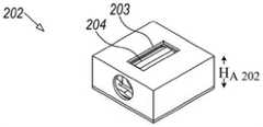
图2A所示意的是本发明折叠相机的各构件,本发明折叠相机在示例性坐标系XYZ中标注为200。折叠相机200包括降低高度的透镜促动器202,所述透镜促动器202具有顶部开孔203、透镜204、OPFE 206和图像传感器208,也参阅图2-9。Illustrated in FIG. 2A are the components of the folding camera of the present invention, which is labeled 200 in an exemplary coordinate system XYZ. The
OPFE 206将来自对象或场景210的光沿平行于Y方向的第一方向(入口光轴)212转向到平行于所述Z方向第二方向(透镜光轴)214,朝向图像传感器208。
图2B-2E提供透镜促动器202的各种视图。图2B所示为透镜促动器202的俯视立体示意图,图2C为除去上外壳部分216的透镜促动器202的俯视立体示意图。图2D所示为具有分离的上部外壳部分216的透镜促动器202的仰视立体示意图。箭头260显示上部外壳部分216安装的方向。图2E所示为促动器202沿图2A中的C-C和D-D部分之间的部分的截面示意图。顶部开孔203允许上部高度容余234比透镜促动器102的上部高度容余134小。上部高度容余(空气间隙)234在所述上部外壳部分216的透镜顶部表面238和外顶部表面224之间测量而得。上部高度容余(空气间隙)234等于沿着所述第一方向(Y轴)测量的透镜顶部表面238和外顶部表面224之间的空气间隙的大小。第二空气间隙232相对于空气间隙234位于透镜204的正对侧。空气间隙232在透镜204和底部外壳部分220的内表面236之间,并且允许透镜204相对于底部外壳部分220的移动。在一些实例中,HA202等于所述透镜高度HL加两个空气间隙234和232的尺寸加底部外壳部分220的厚度。示例性地,空气间隙234和/或232的尺寸可以是50-150μm,底部外壳部分220的厚度可以是100-150μm,并且透镜促动器高度HA202可以等于HL加250μm-500μm。所有其它尺寸都相等,折叠相机200中透镜促动器高度HA202会比折叠相机100中的透镜促动器高度HA102小。2B-2E provide various views of the
相似于折叠相机200,图2F所示为本发明另一实施例的折叠相机并标注为250。相机250包括具有透镜促动器高度HA202的透镜促动器202,并载有透镜204。图像传感器208固定在图像传感器固持件252中。OPFE 206固定在棱镜固持件254中。另外地,在某些实施例中,IR滤波器256可选择地定位于透镜204和图像传感器208之间。图2G所示为沿图2F的折叠相机250的D’-D’线截取的侧视图。在相机250中,折叠相机高度HFC由HA202、HP和HS的最大值限定。如此,HA202的减少会导致HFC的减少。Similar to the
可替换地,对于给定的折叠相机高度,具有更好的光学特性的更高的透镜(即具有大的HL的透镜)可在具有开孔的设计方案中使用,相对于没有开孔的设计。明显地,因其对于相同的光学特性具有更低的相机高度、或者由于对相同相机高度具有更好的光学特性,相机250的设计比相机150的设计具有优势。Alternatively, for a given folded camera height, taller lenses with better optical properties (ie, lenses with largeHL ) can be used in designs with apertures, relative to those without apertures. design. Clearly, the design of
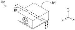
图3A-3E提供透镜促动器302的第二实施例的各种视图,其中所述透镜促动器外壳314在底盖306中设有底部开孔304。透镜促动器302相似于透镜促动器202,并且能够以相似的方式安装在诸如折叠相机200的折叠相机中。图3A显示的是驱动透镜310的透镜促动器302的俯视图,图3B所示为没有上部外壳部分的透镜促动器302的俯视图。图3C所示为透镜促动器302的仰视图。图3D显示了没有上部外壳部分的透镜促动器302的仰视图,并且图3E所示为透镜促动器302沿图3A中的A-A和B-B部分之间的部分的截面示意图。底部开孔304允许更低的高度容余(空气间隙)336,并等于沿着所述第一方向(Y轴)测量的所述透镜的底部表面324和底部外壳部分306的外底部表面328之间的空气间隙。即,更低的高度容余336比图1A中的更低的高度容余136更小。相对于空气间隙336,第二空气间隙332位于透镜310的正对侧上。空气间隙232设于透镜310和上部外壳部分360的所述内表面362之间,并允许透镜310相对于上部外壳部分360的移动。在一些实例中,HA302等于HL加两个空气间隙332和336的尺寸加上部外壳部分360的厚度。示例性地,每个空气间隙332和336的高度可以是50-150μm,上部外壳部分360的厚度可以是100-150μm,并且HA302可以等于所述透镜高度HL加250μm-500μm。所有其它尺寸是相等的,相机300的透镜促动器高度HA302会比相机100的透镜促动器高度HA102更小。像透镜促动器202,透镜促动器302可以组合到折叠相机中,位于OPFE和图像传感器之间,以使得所述折叠相机的高度HFC等于所述透镜促动器的高度HA302。FIGS. 3A-3E provide various views of a second embodiment of a
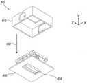
图4A-4C提供驱动透镜410的折叠透镜促动器402的第三实施例的各种视图,其中透镜促动器外壳414具有底部开孔和顶部开孔。图4A显示了透镜促动器402的俯视图,图4B所示为具有分离的上外壳部分416的透镜促动器402的仰视图,并且图4C所示为透镜促动器402在图4A中G-G和H-H部分之间的截面示意图。箭头460显示的是上外壳部分216的安装方向。透镜促动器402包括具有像透镜促动器202中的开孔203的开孔403的上部外壳部分416、和具有像透镜促动器302中的开孔304的开孔404的底部外壳部分406。两个开孔403和404定位于透镜410的正相对的两侧上。因而,透镜促动器402结合了由透镜促动器202的顶部开孔203和透镜促动器302的底部开孔304提供的优势,并具有小于促动器102、202和302中的透镜促动器高度的最终透镜促动器高度HA402。在一些实例中,透镜促动器高度HA402等于所述透镜高度加两个空气间隙418的尺寸。示例性地,每个空气间隙418和432的大小可以是50-150μm,并且透镜促动器高度HA402可以等于HL加100μm或250μm或300μm。像透镜促动器202,透镜促动器402可以组合在折叠相机中,位于OPFE和图像传感器之间,以使得所述折叠相机的高度HFC等于所述透镜促动器的高度HA402。4A-4C provide various views of a third embodiment of a folded
图5A、5B、6、7、8和9显示了使用VCM驱动的示例性透镜促动器设计方案。这样的设计可以与透镜促动器202、302和402的外壳设计一起使用。Figures 5A, 5B, 6, 7, 8 and 9 show exemplary lens actuator designs using VCM drive. Such a design can be used with the housing designs of
图5A和图5B分别显示了VCM 502的仰视和俯视立体分解图。VCM 502包括外壳506、OIS/AF板次组件508、四个上部球体510、透镜载座次组件512、透镜514、四个下部球体516、电子次组件530、基座次组件540和下部板522。VCM 502能够在两个正交方向上驱动如上文所描述的任何透镜,例如用于对焦和光学图像稳定。5A and 5B show bottom and top perspective exploded views of
图6所示为电子次组件530的立体分解图。电子次组件530包括OIS霍尔棒传感器(OIS Hall bar sensor)602、OIS线圈604、AF霍尔棒传感器(AF Hall bar sensor)606、第一刚性印刷电路板(PCB)608、第二刚性PCB610和柔性PCB612。本说明书上文和下文所描述的任何一种透镜的控制都可使用由霍尔棒传感器602和606允许的位置感测在闭环模式来实现。FIG. 6 shows an exploded perspective view of the
图7所示为基座次组件540的立体分析图。基座次组件540包括AF VCM704、AF步进轭702和基座706。FIG. 7 is an exploded perspective view of the
图8所示为透镜载座次组件512的立体分解图。透镜载座次组件包括OIS VCM磁体804、OIS感测磁体802和透镜载座806。FIG. 8 shows an exploded perspective view of the
图9所示为OIS/AF板次组件508的立体分解图。OIS/AF板次组件508包括AF电机磁体902、OIS步进轭904和OIS/AF板906。FIG. 9 shows an exploded perspective view of the OIS/
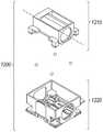
图10-14显示的是使用VCM驱动的另一示例性透镜促动器。图10A所示为根据本发明某些方面的使用VMC驱动的透镜促动器1004的立体分解图。透镜促动器1004包括用于所述透镜和其它机械部件的保护的外壳1014、具有透镜光轴1012的透镜1016、透镜载座(固持件)1018、复数(例如四)个步进磁体1020a,b,c和d、OIS磁体1022、四个上部球体1024、AF磁体1026、中间支架1028、四个下部球体1030、基座1032、复数个(例如四个)上部步进轭1034a,b,c和d、AF霍尔传感器棒(Hall sensor bar)1036、AF线圈1038、用作旋转电子元件及其之间电性链路的平台的PCB1042、OIS霍尔传感器棒1044和用作所述相机的底部机械保护的下部板1048。在一些实施例中,所述步进轭中的一些可以设于第一表面上,而另一些步进轭可以设于第二表面上,其中所述第一表面和所述第二表面是平行的。10-14 show another exemplary lens actuator driven using a VCM. 10A shows an exploded perspective view of a
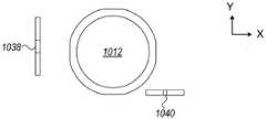
图10B和10C从两个不同的视角显示了AF线圈1038和OIS线圈1040相对于所述透镜光轴1012的定位。每个线圈具有体育场形状(stadium shape),使得其具有两个长的尺寸(典型地是1-5mm长)和一个短的尺寸(典型地是0.1-0.5mm厚)。每个线圈典型地具有几十个绕组(例如,在非限制性范围50-250),具有10-30ohm的示例性阻抗。所述线圈的所述长的尺寸所在的所述平面可被认为是相应的“线圈平面”。在所示的实例中,OIS线圈1040的“OIS线圈平面”平行于XZ平面,即它的两个长尺寸位于XZ平面里而它的短尺寸则沿着Y轴。在所示的实例中,AF线圈1038的“AF线圈平面”平行于YZ平面,即它的两个长尺寸位于YZ平面里而它的短尺寸沿着X轴。如此,在该实例中,所述OIS线圈平面垂直于所述AF线圈平面。在本发明的实施例中,OIS线圈1040面对OIS磁体1022(图10A)。所述OIS磁体是固定的(即,永久性的)磁体。磁体1022可以制造(例如,烧结,切割)为使得它具有变化的磁场极性:在其正X尺寸,OIS磁体1022具有面向所述负Y方向的磁场,而在其负X侧,OIS磁体1022具有面向所述正Y方向的磁场。一旦驱动OIS线圈1040中的电流,OIS磁体1022的磁场在OIS线圈1040上产生所述负或正Y方向的洛伦兹力(Lorenz force)。因此,在所述Y方向有相等的力施加在OIS磁体1022上。在XZ平面中具有OIS线圈1040具有这样的优势,当在驱动过程中,OIS磁体被保持在离OIS线圈1022恒定的距离处。即,用于OIS的洛伦兹力对于不同的AF位置是均匀的,并且所述OIS位置读数对于OIS移动/运动是线性的、和对于不同AF位置是均匀的。10B and 10C show the positioning of the
在图10B所示的实例中,透镜光轴1012是沿Z方向。OIS和AF平面的每一个平行于透镜光轴1012。另外,相对于由所述第一光轴1010和所述第二(透镜)光轴1012界定的平面,所述OIS线圈和所述AF线圈位于此平面的相对侧上。此特点具有降低所述两个VCM的磁场干涉的优点。In the example shown in FIG. 10B, the lens
在实施例中,AF线圈1038面对AF磁体1026。所述AF磁体是固定的(即,永久性的)磁体。AF磁体1026可以制作(例如烧结,切割)为使得它具有变化的磁场极性:在其正Z尺寸上,AF磁体1026具有面对所述负X方向的磁场,而在其负Z侧OIS磁体1022具有面对所述正X方向的磁场。一旦驱动AF线圈1038里的电流,AF磁体1026的所述磁场在AF线圈1038上在所述负或正Z方向上产生洛伦兹力。因此,在所述Z方向上对AF磁体1026施加相等的力。在YZ平面里具有AF线圈1038具有这样的优势,在驱动过程中,所述AF磁体保持在离OIS线圈1040恒定距离处。即,用于AF的所述洛伦兹力对于不同OIS位置是均匀的,并且所述AF位置读数对于AF移动来说是线性的和对于不同OIS位置来说是均匀的。In an embodiment, the
图10D所示为类似于VCM 1004中的外壳1014的外壳1014’,其具有增加的顶部开孔1062。图10E所示为相似于VCM 1004的下部板1048的下部板1048’,其具有增加的底部开孔1064。开孔1062和1064以相似于上文描述的开孔203和304的方式降低VCM 1004的高度。关于顶部和底部开孔的好处,实施例202、302、402的描述适用于VCM 1004的描述并可用于VCM1004中。Figure 10D shows a housing 1014' similar to
图11A和11B显示了包括在透镜促动器1004的第一VCM促动器1100的两个不同视角的分解示意图。在实例中,VCM促动器1100可用于AF。在另一实例中,VCM促动器1100可用于OIS。在VCM促动器1100中,顶部驱动次组件1110相对于AF静止次组件1120在平行于光轴1012的方向是可动的。顶部驱动次组件1110包括透镜1016、透镜固持体1018、中间支架1028、AF磁体1026和四个步进磁体1020a,b,c和d、OIS磁体1022、和四个上部球体1024。中间支架1028和AF磁体1026形成中间驱动次组件1130。AF静止次组件1120包括下部步进轭1050、OIS霍尔传感器棒1044、印刷电路板1042、OIS线圈1040、AF线圈1038、AF霍尔传感器棒1036、四个上部步进轭1034a,b,c和d、以及基座1032(在图示中仅有部分可见)。中间驱动次组件1130相对AF静止次组件1120在平行于光轴1012的方向上是可动的,并且相对于透镜驱动次组件1210在垂直于光轴1012的方向上是可移动的。11A and 11B show exploded schematic views of two different viewing angles of the
图11C和11D分别显示了在中间支架1028中的四个轨道1052和在基座1032中的四个轨道1054。尽管轨道1054中的一个隐在图11D中,本领域技术人员会理解其位置与其他可见的轨道是对称的。Figures 11C and 11D show four
在VCM促动器1100中,所述四个轨道1052中的每一个面对轨道1054中的对应轨道,而下部球体1030中的一个球位于所述轨道之间。所述轨道和球结构限制了顶部驱动次组件1110在平行于光轴1012的方向上相对AF静止次组件1120的移动。另外,由于磁体1020的磁力和上部步进轭1034(可参下),顶部驱动次组件1110在所述Y方向上被拉向AF静止次组件1120;而球体1030在所述Y方向上保持顶部驱动次组件1110和AF静止次组件1120之间的距离恒定。在本说明书中,相对移动部件的术语“恒定距离(constant distance)”指的是在垂直于移动方向的方向上所述部件之间的距离是恒定的,可具有±10μm、±30μm、±50μm、或者甚至是±100μm的公差。In the
图12A和12B所示为透镜次组件10004的第二VCM促动器1200的俯视和仰视图。VCM促动器1200包括相对OIS静止次组件1220为可移动的透镜驱动次组件1210。VCM促动器1200可用于OIS。透镜驱动次组件1210包括透镜1016、透镜固持体1018、四个步进磁体1020和OIS磁体1022(其也是顶部驱动次组件1110的部分)。OIS静止次组件1220包括透镜固持体1018、中间支架1028、AF磁体1026、AF静止次组件1120和所述四个下部球体1030。12A and 12B show top and bottom views of the
图12C和12D所示分别为透镜固持体1018中的四个轨道和中间支架1028中的四个轨道1058。在VCM促动器1200中,所述四个轨道1056的每一个面对轨道1058中对应的轨道,而上部球体1024的一个球体设于所述轨道之间。所述轨道和球体结构限制透镜驱动次组件1210在垂直于光轴1012的方向上相对OIS静止驱动次组件1220的移动。另外,由于磁体1020a,b,c和d的磁力和步进轭1034a,b,c和d(可参阅下文),透镜驱动次组件1210在所述Y方向上被拉向OIS静止次组件1220,而上部球体1024保持透镜驱动次组件1210和OIS静止次组件1220之间的距离在所述Y方向上恒定。Figures 12C and 12D show four rails in
在一些实施例中,所述透镜驱动次组件被拉向所述静止次组件,而中间驱动次组件位于二者之间。In some embodiments, the lens drive subassembly is drawn toward the stationary subassembly with an intermediate drive subassembly therebetween.
在使用促动器1100用于AF时,AF线圈1038中的电流产生作用于AF磁体1026的力,在平行于透镜光轴1012的方向(例如沿着所述正或负Z方向)驱动中间支架1028。中间支架1028固持住透镜驱动次组件1210,并且当在所述AF方向移动时带着透镜驱动次组件1210一起移动,使得透镜1016被操作来根据光学要求在图像传感器1006上对焦。通过在位于中间支架1028中的所述四个对应的轨道1052中、以及位于基座1032中的四个对应轨道1054中滚动和/或滑动所述四个下部球体1030来引导所述AF的移动。When using the
在使用促动器1200用于OIS时,OIS线圈1040中的电流产生作用于OIS磁体1022的力,在垂直于所述透镜光轴1012并且平行所述X轴(如在示例性坐标系XYZ中所显示的)的方向上驱动透镜固持体1018。在这个移动过程中,透镜固持体1018(其固持住1016)和所述透镜在任意OIS方向一起移动。通过在位于透镜固持体1018上的所述四个对应的轨道1052中、以及位于所述中间支架1028上的四个对应轨道1054中滚动和/或滑动所述四个下部球体1030来引导所述OIS的移动。When using the
设于所述透镜固持体1018的所述四个步进磁体1020a,1020b,1020c和1020d与位于AF静止次组件1120上的四个步进轭1034a,1034b,1034c和1034d相关联,产生由箭头所指示的在垂直于光轴1012方向上的步进力。步进磁体1020a-d和步进轭1034a-d在图13A中可见,显示VCM 1100的立体分解图,而图13B仅显示所述磁体和轭沿着所述力的方向,其指示在负Y方向上。在实施例中,透镜驱动次组件1210被拉向AF静止次组件1120,而OIS次组件1220设于二者之间。位于透镜驱动次组件1210和OIS静止次组件1220之间的上部球体1024防止所述两个次组件之间的接触。类似地,位于OIS静止次组件1220和AF静止次组件1120之间的下部球体1030防止所述两个次组件之间的接触。同时,产生在四个步进磁体1020和四个步进轭1034之间的所述拉力将促动器1100固持为一个单元/整体,并防止所有移动部件分离开。在一些实例中,所述三个步进磁体仅用于步进,而所述四个磁体用于步进和感测。The four
图14A和14B分别显示顶部驱动次组件1110的立体分解图和组装示意图。在一些实施例中,透镜固持体1018具有允许光从OPFE穿过到达透镜1016的开孔1402。开孔1402由壁体1404a,b,c,和d围绕。在实施例中,中间支架1028包括壁体1406a,b,c和d。壁体1406b可用来增加机械强度和所述轨道之间的连接。图14C和14D显示两个不同的实施例沿顶部驱动次组件1110和棱镜1410的光轴的截面示意图。图14C和14D所示的实施例描述了壁体1406b和1404b的两个相对的位置。在图14C的实施例中,壁体1406b位于壁体1404b(在所述-Y方向)的下方。Figures 14A and 14B show an exploded perspective view and a schematic assembly view of the
相对地,在图14D的实施例中壁体1406b’代替壁体1406b,并位于壁体1404b旁边(在所述-Z方向)。距离1408指示从棱镜到顶部驱动次组件1110的最小距离。距离1408由顶部驱动次组件1110的用于AF的一次冲程(a stroke for AF)来决定,如光学需要和组装公差及机械需要所要求的。距离1408在两种布置(图14C和14D)中都是恒定的。因而,图14C中的布置具有优势,由于它允许沿所述光轴方向(-Z方向)更短的促动器,即折叠相机1000(图10A)长度的减小。In contrast, in the embodiment of Figure 14D, wall 1406b'
图15所示为双相机1500,其包括直立式相机1502和折叠相机1504。折叠相机1504可包括类似于上文描述的任何促动器/VCM的透镜促动器,例如促动器/VCMs 102、202、302、402、502或1004。FIG. 15 shows a
尽管本说明书中描述了有限数据的实施例,然而应理解的是可以对这些实施例进行多种改变、修改和其它的应用。总地来说,本发明不限于本说明书中的实施例,而仅由权利要求书的范围界定。Although embodiments with limited data are described in this specification, it should be understood that various changes, modifications, and other applications may be made to these embodiments. In general, the invention is not limited to the embodiments described in this specification, but is only defined by the scope of the claims.
本说明书所提到的所有参考文献都全文并入本说明书中,如同每个参考文献被明确和单独指出要被包括到本发明中去的程度。另外,所引用的或指出的任何参考文献不应被解释为承认这些参考文献可作为本发明的现有技术。All references mentioned in this specification are incorporated in their entirety into this specification to the same extent as if each reference was specifically and individually indicated to be incorporated into the present invention. In addition, any reference cited or indicated should not be construed as an admission that such reference is available as prior art to the present invention.
Claims (12)
Translated fromChineseApplications Claiming Priority (10)
| Application Number | Priority Date | Filing Date | Title |
|---|---|---|---|
| US201862626306P | 2018-02-05 | 2018-02-05 | |
| US62/626,306 | 2018-02-05 | ||
| US201862658819P | 2018-04-17 | 2018-04-17 | |
| US62/658,819 | 2018-04-17 | ||
| US201862672754P | 2018-05-17 | 2018-05-17 | |
| US62/672,754 | 2018-05-17 | ||
| US201862677012P | 2018-05-27 | 2018-05-27 | |
| US62/677,012 | 2018-05-27 | ||
| PCT/IB2018/060203WO2019150188A1 (en) | 2018-02-05 | 2018-12-17 | Reduced height penalty for folded camera |
| CN201880014197.0ACN110352371B (en) | 2018-02-05 | 2018-12-17 | Folding camera device capable of reducing height allowance |
Related Parent Applications (1)
| Application Number | Title | Priority Date | Filing Date |
|---|---|---|---|
| CN201880014197.0ADivisionCN110352371B (en) | 2018-02-05 | 2018-12-17 | Folding camera device capable of reducing height allowance |
Publications (1)
| Publication Number | Publication Date |
|---|---|
| CN114609746Atrue CN114609746A (en) | 2022-06-10 |
Family
ID=67478638
Family Applications (2)
| Application Number | Title | Priority Date | Filing Date |
|---|---|---|---|
| CN202210343497.1APendingCN114609746A (en) | 2018-02-05 | 2018-12-17 | Folding camera device |
| CN201880014197.0AActiveCN110352371B (en) | 2018-02-05 | 2018-12-17 | Folding camera device capable of reducing height allowance |
Family Applications After (1)
| Application Number | Title | Priority Date | Filing Date |
|---|---|---|---|
| CN201880014197.0AActiveCN110352371B (en) | 2018-02-05 | 2018-12-17 | Folding camera device capable of reducing height allowance |
Country Status (5)
| Country | Link |
|---|---|
| US (4) | US10976567B2 (en) |
| EP (3) | EP3848749A1 (en) |
| KR (3) | KR102242452B1 (en) |
| CN (2) | CN114609746A (en) |
| WO (1) | WO2019150188A1 (en) |
Families Citing this family (16)
| Publication number | Priority date | Publication date | Assignee | Title |
|---|---|---|---|---|
| US10884321B2 (en)* | 2017-01-12 | 2021-01-05 | Corephotonics Ltd. | Compact folded camera |
| US11333955B2 (en)* | 2017-11-23 | 2022-05-17 | Corephotonics Ltd. | Compact folded camera structure |
| US11243455B2 (en)* | 2019-09-25 | 2022-02-08 | Apple Inc. | Camera with folded optics |
| EP4303643A3 (en) | 2020-01-22 | 2024-05-29 | Tdk Taiwan Corp. | Optical system |
| TWI730637B (en) | 2020-02-24 | 2021-06-11 | 大陽科技股份有限公司 | Camera module and electronic device |
| US12212829B2 (en) | 2020-06-18 | 2025-01-28 | Lg Innotek Co., Ltd. | Camera module and optical instrument comprising same |
| WO2022034402A1 (en)* | 2020-08-12 | 2022-02-17 | Corephotonics Ltd. | Optical image stabilization in a scanning folded camera |
| CN114167570B (en)* | 2020-09-10 | 2023-06-06 | 华为技术有限公司 | Optical lens, camera module, electronic equipment and shooting method of camera module |
| CN114430455A (en) | 2020-10-29 | 2022-05-03 | 华为技术有限公司 | Image sensor anti-shake assembly, camera device and electronic equipment |
| US12271105B2 (en)* | 2020-11-05 | 2025-04-08 | Corephotonics Ltd. | Scanning Tele camera based on two prism field of view scanning |
| CN112637471B (en)* | 2020-12-23 | 2022-02-08 | 维沃移动通信有限公司 | Camera module and electronic equipment |
| KR102460759B1 (en)* | 2021-01-27 | 2022-10-31 | 삼성전기주식회사 | Ois circuit of folded zoom type and camera device having the same |
| CN115086507B (en)* | 2021-03-10 | 2023-08-22 | 宁波舜宇光电信息有限公司 | Telescopic camera module and electronic equipment |
| CN116264845A (en) | 2021-08-17 | 2023-06-16 | 三星电子株式会社 | Camera module including folded optics |
| TWI793978B (en)* | 2021-12-02 | 2023-02-21 | 大陽科技股份有限公司 | Photographing module and electronic device |
| WO2024191213A1 (en)* | 2023-03-16 | 2024-09-19 | 삼성전자 주식회사 | Camera actuator and electronic device comprising same |
Citations (11)
| Publication number | Priority date | Publication date | Assignee | Title |
|---|---|---|---|---|
| US20090109556A1 (en)* | 2007-10-31 | 2009-04-30 | Sony Corporation | Lens barrel and imaging apparatus |
| US20110121666A1 (en)* | 2009-11-20 | 2011-05-26 | Lg Innotek Co., Ltd. | Voice Coil Motor |
| KR20140144126A (en)* | 2013-06-10 | 2014-12-18 | 삼성전자주식회사 | Camera lens assembly |
| CN104798364A (en)* | 2012-06-07 | 2015-07-22 | 数位光学欧洲有限公司 | MEMS fast focus camera module |
| CN106164766A (en)* | 2014-04-04 | 2016-11-23 | 高通股份有限公司 | Auto-focusing in low-profile folded optics multicamera system |
| WO2017037688A1 (en)* | 2015-09-06 | 2017-03-09 | Corephotonics Ltd. | Auto focus and optical image stabilization with roll compensation in a compact folded camera |
| CN106576138A (en)* | 2014-08-10 | 2017-04-19 | 核心光电有限公司 | Zoom Dual Aperture Camera with Folded Lens |
| US20170187962A1 (en)* | 2015-12-23 | 2017-06-29 | Samsung Electronics Co., Ltd. | Imaging device module, user terminal apparatus including the imaging device module, and a method of operating the imaging device module |
| CN107533211A (en)* | 2015-04-16 | 2018-01-02 | 核心光电有限公司 | Autofocus and Optical Image Stabilization in a Compact Folding Camera |
| US20180017844A1 (en)* | 2016-07-12 | 2018-01-18 | Tdk Taiwan Corp. | Lens driving module |
| CN107608052A (en)* | 2016-07-12 | 2018-01-19 | 台湾东电化股份有限公司 | Lens driving module |
Family Cites Families (419)
| Publication number | Priority date | Publication date | Assignee | Title |
|---|---|---|---|---|
| US3085354A (en) | 1957-01-31 | 1963-04-16 | Westinghouse Electric Corp | Multi-gimbal flight simulator |
| US3584513A (en) | 1969-01-06 | 1971-06-15 | Singer General Precision | Self-calibrating system for navigational instruments |
| US3941001A (en) | 1973-11-09 | 1976-03-02 | Lear Siegler, Inc. | Gimbal control mechanism |
| US4199785A (en) | 1979-01-05 | 1980-04-22 | Honeywell Inc. | Electronic zoom system |
| JPS59191146A (en) | 1983-04-13 | 1984-10-30 | Hitachi Ltd | Optical scanner |
| US5099263A (en) | 1984-11-10 | 1992-03-24 | Minolta Camera Kabushiki Kaisha | Variable focal length camera |
| JPH0690350B2 (en) | 1986-12-15 | 1994-11-14 | 富士写真光機株式会社 | camera |
| DE58902538D1 (en) | 1988-05-19 | 1992-12-03 | Siemens Ag | METHOD FOR OBSERVING A SCENE AND DEVICE FOR IMPLEMENTING THE METHOD. |
| DE3927334C1 (en) | 1989-08-18 | 1991-01-10 | Messerschmitt-Boelkow-Blohm Gmbh, 8012 Ottobrunn, De | |
| JP2703105B2 (en) | 1989-10-20 | 1998-01-26 | 富士写真フイルム株式会社 | Image stabilization device |
| US5032917A (en) | 1990-03-12 | 1991-07-16 | Rca Licensing Corporation | Video signal blending apparatus |
| JPH0443773A (en) | 1990-06-11 | 1992-02-13 | Matsushita Electric Ind Co Ltd | Arithmetic circuit |
| US5041852A (en) | 1990-10-18 | 1991-08-20 | Fjui Photo Film Co., Ltd. | Camera shake correction system |
| JP3261152B2 (en) | 1991-03-13 | 2002-02-25 | シャープ株式会社 | Imaging device having a plurality of optical systems |
| US5394520A (en) | 1991-09-26 | 1995-02-28 | Hughes Aircraft Company | Imaging apparatus for providing a composite digital representation of a scene within a field of regard |
| US5657402A (en) | 1991-11-01 | 1997-08-12 | Massachusetts Institute Of Technology | Method of creating a high resolution still image using a plurality of images and apparatus for practice of the method |
| JP3103166B2 (en) | 1991-11-26 | 2000-10-23 | 富士写真光機株式会社 | Macro lens with a long exit pupil |
| US5248971A (en) | 1992-05-19 | 1993-09-28 | Mandl William J | Method and apparatus for multiplexed oversampled analog to digital modulation |
| JP3218730B2 (en) | 1992-10-19 | 2001-10-15 | 株式会社ニコン | Focus adjustment device with prediction function |
| JPH06177706A (en) | 1992-12-08 | 1994-06-24 | Sony Corp | Signal processing unit |
| KR940017747A (en) | 1992-12-29 | 1994-07-27 | 에프. 제이. 스미트 | Image processing device |
| US5682198A (en) | 1993-06-28 | 1997-10-28 | Canon Kabushiki Kaisha | Double eye image pickup apparatus |
| US5805140A (en) | 1993-07-16 | 1998-09-08 | Immersion Corporation | High bandwidth force feedback interface using voice coils and flexures |
| US6128416A (en) | 1993-09-10 | 2000-10-03 | Olympus Optical Co., Ltd. | Image composing technique for optimally composing a single image from a plurality of digital images |
| JP3355787B2 (en) | 1994-05-20 | 2002-12-09 | ソニー株式会社 | Optical axis correction mechanism |
| US6714665B1 (en) | 1994-09-02 | 2004-03-30 | Sarnoff Corporation | Fully automated iris recognition system utilizing wide and narrow fields of view |
| CA2155719C (en) | 1994-11-22 | 2005-11-01 | Terry Laurence Glatt | Video surveillance system with pilot and slave cameras |
| JPH08271976A (en) | 1995-03-29 | 1996-10-18 | Canon Inc | camera |
| JPH0995194A (en) | 1995-09-29 | 1997-04-08 | Aisin Seiki Co Ltd | Object detection device in front of the vehicle |
| US5768443A (en) | 1995-12-19 | 1998-06-16 | Cognex Corporation | Method for coordinating multiple fields of view in multi-camera |
| US5982951A (en) | 1996-05-28 | 1999-11-09 | Canon Kabushiki Kaisha | Apparatus and method for combining a plurality of images |
| US5926190A (en) | 1996-08-21 | 1999-07-20 | Apple Computer, Inc. | Method and system for simulating motion in a computer graphics application using image registration and view interpolation |
| JPH10126796A (en) | 1996-09-12 | 1998-05-15 | Eastman Kodak Co | Digital camera for dynamic and still images using dual mode software processing |
| US5960218A (en) | 1997-02-18 | 1999-09-28 | Mobi Corporation | Dual focal length camera |
| US5940641A (en) | 1997-07-10 | 1999-08-17 | Eastman Kodak Company | Extending panoramic images |
| GB9720911D0 (en) | 1997-10-03 | 1997-12-03 | Britax Rainsfords Pty Ltd | Hall effect sensor system |
| US6148120A (en) | 1997-10-30 | 2000-11-14 | Cognex Corporation | Warping of focal images to correct correspondence error |
| US6268611B1 (en) | 1997-12-18 | 2001-07-31 | Cellavision Ab | Feature-free registration of dissimilar images using a robust similarity metric |
| JP3695119B2 (en) | 1998-03-05 | 2005-09-14 | 株式会社日立製作所 | Image synthesizing apparatus and recording medium storing program for realizing image synthesizing method |
| US6208765B1 (en) | 1998-06-19 | 2001-03-27 | Sarnoff Corporation | Method and apparatus for improving image resolution |
| GB9823689D0 (en) | 1998-10-30 | 1998-12-23 | Greenagate Limited | Improved methods and apparatus for 3-D imaging |
| US6211668B1 (en) | 1998-12-09 | 2001-04-03 | Cts | Magnetic position sensor having opposed tapered magnets |
| US6611289B1 (en) | 1999-01-15 | 2003-08-26 | Yanbin Yu | Digital cameras using multiple sensors with multiple lenses |
| JP3861855B2 (en) | 1999-01-21 | 2006-12-27 | 日本電気株式会社 | Image input device |
| US20020075258A1 (en) | 1999-05-12 | 2002-06-20 | Imove Inc. | Camera system with high resolution image inside a wide angle view |
| US20020063711A1 (en) | 1999-05-12 | 2002-05-30 | Imove Inc. | Camera system with high resolution image inside a wide angle view |
| US6738073B2 (en) | 1999-05-12 | 2004-05-18 | Imove, Inc. | Camera system with both a wide angle view and a high resolution view |
| US6346950B1 (en) | 1999-05-20 | 2002-02-12 | Compaq Computer Corporation | System and method for display images using anamorphic video |
| US6222359B1 (en) | 1999-06-18 | 2001-04-24 | Cts Corporation | Non-contacting position sensor using radial bipolar tapered magnets |
| US7038716B2 (en) | 1999-07-30 | 2006-05-02 | Pixim, Inc. | Mobile device equipped with digital image sensor |
| US7015954B1 (en) | 1999-08-09 | 2006-03-21 | Fuji Xerox Co., Ltd. | Automatic video system using multiple cameras |
| US6650368B1 (en) | 1999-10-26 | 2003-11-18 | Hewlett-Packard Development Company, Lp. | Digital camera and method of enhancing zoom effects |
| US6643416B1 (en) | 1999-11-30 | 2003-11-04 | Eastman Kodak Company | Method for determining necessary resolution for zoom and crop images |
| US20020005902A1 (en) | 2000-06-02 | 2002-01-17 | Yuen Henry C. | Automatic video recording system using wide-and narrow-field cameras |
| JP2002010276A (en) | 2000-06-22 | 2002-01-11 | Olympus Optical Co Ltd | Imaging apparatus |
| JP4501239B2 (en) | 2000-07-13 | 2010-07-14 | ソニー株式会社 | Camera calibration apparatus and method, and storage medium |
| US7002583B2 (en) | 2000-08-03 | 2006-02-21 | Stono Technologies, Llc | Display of images and image transitions |
| US6778207B1 (en) | 2000-08-07 | 2004-08-17 | Koninklijke Philips Electronics N.V. | Fast digital pan tilt zoom video |
| US7345277B2 (en) | 2000-08-09 | 2008-03-18 | Evan Zhang | Image intensifier and LWIR fusion/combination system |
| JP2002099014A (en) | 2000-09-22 | 2002-04-05 | Nikon Corp | Signal prediction device and camera having the same |
| JP2002214662A (en) | 2001-01-23 | 2002-07-31 | Olympus Optical Co Ltd | Shake correcting device for optical device |
| US6741250B1 (en) | 2001-02-09 | 2004-05-25 | Be Here Corporation | Method and system for generation of multiple viewpoints into a scene viewed by motionless cameras and for presentation of a view path |
| GB2372659A (en) | 2001-02-23 | 2002-08-28 | Sharp Kk | A method of rectifying a stereoscopic image |
| US7346217B1 (en) | 2001-04-25 | 2008-03-18 | Lockheed Martin Corporation | Digital image enhancement using successive zoom images |
| JP2002341220A (en)* | 2001-05-14 | 2002-11-27 | Olympus Optical Co Ltd | Optical instrument |
| GB0116877D0 (en) | 2001-07-10 | 2001-09-05 | Hewlett Packard Co | Intelligent feature selection and pan zoom control |
| US6680748B1 (en) | 2001-09-27 | 2004-01-20 | Pixim, Inc., | Multi-mode camera and method therefor |
| US20030093805A1 (en) | 2001-11-15 | 2003-05-15 | Gin J.M. Jack | Dual camera surveillance and control system |
| US7339621B2 (en) | 2001-12-13 | 2008-03-04 | Psion Teklogix Systems, Inc. | Imager output signal processing |
| JP4198449B2 (en) | 2002-02-22 | 2008-12-17 | 富士フイルム株式会社 | Digital camera |
| JP2003298920A (en) | 2002-03-29 | 2003-10-17 | Fuji Photo Film Co Ltd | Digital camera |
| JP2003304024A (en) | 2002-04-12 | 2003-10-24 | Nippon Telegr & Teleph Corp <Ntt> | Optical module with built-in drive circuit |
| JP4657564B2 (en) | 2002-04-30 | 2011-03-23 | イーストマン コダック カンパニー | Electronic still camera and image processing method |
| GB2388265B (en) | 2002-04-30 | 2005-10-12 | Hewlett Packard Co | Improvements in and relating to processing of images |
| CA2386560A1 (en) | 2002-05-15 | 2003-11-15 | Idelix Software Inc. | Controlling optical hardware and dynamic data viewing systems with detail-in-context viewing tools |
| JP3870124B2 (en) | 2002-06-14 | 2007-01-17 | キヤノン株式会社 | Image processing apparatus and method, computer program, and computer-readable storage medium |
| US6839067B2 (en) | 2002-07-26 | 2005-01-04 | Fuji Xerox Co., Ltd. | Capturing and producing shared multi-resolution video |
| US20040061788A1 (en) | 2002-09-26 | 2004-04-01 | Logitech Europe S.A. | Multiple mode capture button for a digital camera |
| US7321470B2 (en) | 2002-10-08 | 2008-01-22 | Olympus Corporation | Camera |
| JP4481560B2 (en) | 2002-10-08 | 2010-06-16 | オリンパス株式会社 | Lens barrel |
| GB2394852B (en) | 2002-10-31 | 2006-12-20 | Hewlett Packard Co | Image capture systems using motion detection |
| JP2004219569A (en) | 2003-01-10 | 2004-08-05 | Olympus Corp | Electronic image pickup unit |
| JP3861815B2 (en) | 2003-01-17 | 2006-12-27 | コニカミノルタフォトイメージング株式会社 | Camera with image stabilization function |
| JP4055599B2 (en) | 2003-02-13 | 2008-03-05 | コニカミノルタオプト株式会社 | Imaging lens device and electronic apparatus equipped with the same |
| CN100449268C (en) | 2003-02-14 | 2009-01-07 | Bei传感器及系统有限公司 | Position Sensor with Enhanced Linear Magnet Configuration Using Linear Hall Effect Sensors |
| WO2004084542A1 (en) | 2003-03-20 | 2004-09-30 | Seijiro Tomita | Panoramic picture creating method and device, and monitor system using the method and device |
| CN1574894A (en) | 2003-06-02 | 2005-02-02 | 宾得株式会社 | Multiple-focal imaging device, and a mobile device having the multiple-focal-length imaging device |
| US7596284B2 (en) | 2003-07-16 | 2009-09-29 | Hewlett-Packard Development Company, L.P. | High resolution image reconstruction |
| US7619683B2 (en) | 2003-08-29 | 2009-11-17 | Aptina Imaging Corporation | Apparatus including a dual camera module and method of using the same |
| JP2005099265A (en) | 2003-09-24 | 2005-04-14 | Fujinon Corp | Imaging apparatus, imaging method, and range finding method |
| JP2005122084A (en) | 2003-09-25 | 2005-05-12 | Kyocera Corp | Optical element module |
| EP1536633A1 (en) | 2003-11-27 | 2005-06-01 | Sony Corporation | Photographing apparatus and method, supervising system, program and recording medium |
| US7746396B2 (en) | 2003-12-17 | 2010-06-29 | Nokia Corporation | Imaging device and method of creating image file |
| KR100557040B1 (en) | 2003-12-30 | 2006-03-03 | 엘지전자 주식회사 | Optical pickup system |
| JP2005208194A (en) | 2004-01-21 | 2005-08-04 | Konica Minolta Photo Imaging Inc | Photographing apparatus |
| KR20050090780A (en) | 2004-03-10 | 2005-09-14 | 삼성전자주식회사 | Image photographing apparatus |
| EP1594321A3 (en) | 2004-05-07 | 2006-01-25 | Dialog Semiconductor GmbH | Extended dynamic range in color imagers |
| JP4201140B2 (en) | 2004-05-10 | 2008-12-24 | 株式会社コルグ | Operator |
| WO2006040687A2 (en) | 2004-07-19 | 2006-04-20 | Grandeye, Ltd. | Automatically expanding the zoom capability of a wide-angle video camera |
| JP4894041B2 (en) | 2004-07-20 | 2012-03-07 | 株式会社ファイブ・ディー | Electronic imaging device |
| US7564019B2 (en) | 2005-08-25 | 2009-07-21 | Richard Ian Olsen | Large dynamic range cameras |
| US7916180B2 (en) | 2004-08-25 | 2011-03-29 | Protarius Filo Ag, L.L.C. | Simultaneous multiple field of view digital cameras |
| US20060054782A1 (en) | 2004-08-25 | 2006-03-16 | Olsen Richard I | Apparatus for multiple camera devices and method of operating same |
| US7465107B2 (en) | 2004-09-21 | 2008-12-16 | Canon Kabushiki Kaisha | Photographing apparatus and control method therefor |
| KR101054344B1 (en) | 2004-11-17 | 2011-08-04 | 삼성전자주식회사 | Thin film transistor array panel and manufacturing method thereof |
| EP1669251A1 (en) | 2004-12-07 | 2006-06-14 | IEE INTERNATIONAL ELECTRONICS & ENGINEERING S.A. | Child seat detection system |
| US7688364B2 (en) | 2004-12-10 | 2010-03-30 | Ambarella, Inc. | Decimating and cropping based zoom factor for a digital camera |
| US20060126737A1 (en) | 2004-12-15 | 2006-06-15 | International Business Machines Corporation | Method, system and program product for a camera to track an object using motion vector data |
| KR100636969B1 (en) | 2004-12-30 | 2006-10-19 | 매그나칩 반도체 유한회사 | ISP built-in image sensor and dual camera system |
| US7573514B2 (en) | 2005-02-03 | 2009-08-11 | Eastman Kodak Company | Digital imaging system with digital zoom warning |
| US7663662B2 (en) | 2005-02-09 | 2010-02-16 | Flir Systems, Inc. | High and low resolution camera systems and methods |
| US7646400B2 (en) | 2005-02-11 | 2010-01-12 | Creative Technology Ltd | Method and apparatus for forming a panoramic image |
| US7206136B2 (en) | 2005-02-18 | 2007-04-17 | Eastman Kodak Company | Digital camera using multiple lenses and image sensors to provide an extended zoom range |
| US7236306B2 (en) | 2005-02-18 | 2007-06-26 | Eastman Kodak Company | Digital camera using an express zooming mode to provide expedited operation over an extended zoom range |
| US7256944B2 (en) | 2005-02-18 | 2007-08-14 | Eastman Kodak Company | Compact image capture assembly using multiple lenses and image sensors to provide an extended zoom range |
| US20060187322A1 (en) | 2005-02-18 | 2006-08-24 | Janson Wilbert F Jr | Digital camera using multiple fixed focal length lenses and multiple image sensors to provide an extended zoom range |
| US7561191B2 (en) | 2005-02-18 | 2009-07-14 | Eastman Kodak Company | Camera phone using multiple lenses and image sensors to provide an extended zoom range |
| JP2006237914A (en) | 2005-02-24 | 2006-09-07 | Kyocera Corp | Mobile terminal device |
| JP2006238325A (en) | 2005-02-28 | 2006-09-07 | Canon Inc | Camera system |
| KR100658150B1 (en) | 2005-04-08 | 2006-12-15 | 삼성전기주식회사 | Camera module and its manufacturing method |
| WO2006137253A1 (en) | 2005-06-22 | 2006-12-28 | Matsushita Electric Industrial Co., Ltd. | Image forming device, and image forming method |
| KR20070005946A (en) | 2005-07-05 | 2007-01-11 | 엘지전자 주식회사 | Device for detecting position of camera lens for mobile terminal |
| JP2007033879A (en) | 2005-07-27 | 2007-02-08 | Sony Corp | Imaging lens device and imaging apparatus |
| US7424218B2 (en) | 2005-07-28 | 2008-09-09 | Microsoft Corporation | Real-time preview for panoramic images |
| JP4573724B2 (en) | 2005-08-01 | 2010-11-04 | イーストマン コダック カンパニー | Imaging apparatus having a plurality of optical systems |
| JP4573725B2 (en) | 2005-08-01 | 2010-11-04 | イーストマン コダック カンパニー | Imaging apparatus having a plurality of optical systems |
| US7964835B2 (en) | 2005-08-25 | 2011-06-21 | Protarius Filo Ag, L.L.C. | Digital cameras with direct luminance and chrominance detection |
| JP4188394B2 (en) | 2005-09-20 | 2008-11-26 | フジノン株式会社 | Surveillance camera device and surveillance camera system |
| KR100982685B1 (en) | 2005-10-13 | 2010-09-17 | 알제이에스 테크놀로지, 인코포레이티드 | System and method for high performance color filter mosaic array |
| US7822330B2 (en) | 2005-11-14 | 2010-10-26 | Nikon Corporation | Image blur correction device and camera |
| JP4788953B2 (en) | 2005-11-16 | 2011-10-05 | ソニー株式会社 | Imaging device and zoom lens |
| US8238695B1 (en) | 2005-12-15 | 2012-08-07 | Grandeye, Ltd. | Data reduction techniques for processing wide-angle video |
| US7423540B2 (en) | 2005-12-23 | 2008-09-09 | Delphi Technologies, Inc. | Method of detecting vehicle-operator state |
| US20070177025A1 (en) | 2006-02-01 | 2007-08-02 | Micron Technology, Inc. | Method and apparatus minimizing die area and module size for a dual-camera mobile device |
| JP4669047B2 (en) | 2006-02-06 | 2011-04-13 | ノキア コーポレイション | Method and device for position detection in an imaging system |
| EP1984774A4 (en) | 2006-02-06 | 2010-11-24 | Nokia Corp | OPTICAL IMAGE STABILIZER WITH A CARDANPRISMA |
| JP4579842B2 (en) | 2006-02-06 | 2010-11-10 | イーストマン コダック カンパニー | Imaging device |
| US9182228B2 (en) | 2006-02-13 | 2015-11-10 | Sony Corporation | Multi-lens array system and method |
| JP2007212961A (en)* | 2006-02-13 | 2007-08-23 | Matsushita Electric Ind Co Ltd | Zoom lens system, imaging device and camera |
| JP4622882B2 (en) | 2006-02-21 | 2011-02-02 | カシオ計算機株式会社 | Digital camera |
| US7708478B2 (en) | 2006-04-13 | 2010-05-04 | Nokia Corporation | Actuator mechanism and a shutter mechanism |
| US7773121B1 (en) | 2006-05-03 | 2010-08-10 | The United States Of America As Represented By The Administrator Of The National Aeronautics And Space Administration | High-resolution, continuous field-of-view (FOV), non-rotating imaging system |
| EP2016759A1 (en) | 2006-05-05 | 2009-01-21 | Nokia Corporation | Optical image recording device with small height and high resolution |
| JP2007306282A (en) | 2006-05-11 | 2007-11-22 | Citizen Electronics Co Ltd | The camera module |
| KR100749337B1 (en) | 2006-06-13 | 2007-08-14 | 삼성전자주식회사 | Method and apparatus for photographing using a mobile communication terminal having a plurality of camera lenses |
| US7737379B2 (en) | 2006-07-19 | 2010-06-15 | Witdouck Calvin J | System and method for sorting larvae cocoons |
| US8189100B2 (en) | 2006-07-25 | 2012-05-29 | Qualcomm Incorporated | Mobile device with dual digital camera sensors and methods of using the same |
| US7756330B2 (en) | 2006-07-27 | 2010-07-13 | Eastman Kodak Company | Producing an extended dynamic range digital image |
| US20080030592A1 (en) | 2006-08-01 | 2008-02-07 | Eastman Kodak Company | Producing digital image with different resolution portions |
| US7667762B2 (en) | 2006-08-01 | 2010-02-23 | Lifesize Communications, Inc. | Dual sensor video camera |
| JP2008076485A (en) | 2006-09-19 | 2008-04-03 | Konica Minolta Opto Inc | Lens barrel and imaging apparatus |
| JP2008096584A (en) | 2006-10-10 | 2008-04-24 | Nikon Corp | camera |
| KR101278239B1 (en) | 2006-10-17 | 2013-06-24 | 삼성전자주식회사 | Dual lens optical system and Dual lens camera comprising the same |
| US7697053B2 (en) | 2006-11-02 | 2010-04-13 | Eastman Kodak Company | Integrated display having multiple capture devices |
| KR100856572B1 (en)* | 2006-11-02 | 2008-09-04 | 주식회사 엠씨넥스 | Camera module |
| JP4448844B2 (en) | 2006-11-22 | 2010-04-14 | 富士フイルム株式会社 | Compound eye imaging device |
| KR100871566B1 (en) | 2006-12-04 | 2008-12-02 | 삼성전자주식회사 | Apparatus and method for image stabilization of an image pickup device |
| US7533819B2 (en) | 2007-01-31 | 2009-05-19 | Symbol Technologies, Inc. | Dual camera assembly for an imaging-based bar code reader |
| US7978239B2 (en) | 2007-03-01 | 2011-07-12 | Eastman Kodak Company | Digital camera using multiple image sensors to provide improved temporal sampling |
| US7859588B2 (en) | 2007-03-09 | 2010-12-28 | Eastman Kodak Company | Method and apparatus for operating a dual lens camera to augment an image |
| US7676146B2 (en) | 2007-03-09 | 2010-03-09 | Eastman Kodak Company | Camera using multiple lenses and image sensors to provide improved focusing capability |
| US7683962B2 (en) | 2007-03-09 | 2010-03-23 | Eastman Kodak Company | Camera using multiple lenses and image sensors in a rangefinder configuration to provide a range map |
| US7729602B2 (en) | 2007-03-09 | 2010-06-01 | Eastman Kodak Company | Camera using multiple lenses and image sensors operable in a default imaging mode |
| WO2008123675A1 (en) | 2007-04-06 | 2008-10-16 | Korea Expressway Corporation | Multi-area monitoring system from single cctv having a camera quadratic curved surface mirror structure and it, and unwrapping method for the same |
| JP5040412B2 (en) | 2007-04-18 | 2012-10-03 | ソニー株式会社 | Image pickup device package, image pickup device module, lens barrel, and image pickup apparatus |
| EP2149067A1 (en) | 2007-04-19 | 2010-02-03 | D.V.P. Technologies Ltd. | Imaging system and method for use in monitoring a field of regard |
| US7918398B2 (en) | 2007-06-04 | 2011-04-05 | Hand Held Products, Inc. | Indicia reading terminal having multiple setting imaging lens |
| KR100880672B1 (en) | 2007-07-18 | 2009-02-02 | 자화전자 주식회사 | Camera system with autofocus function and its control method |
| US8390729B2 (en) | 2007-09-05 | 2013-03-05 | International Business Machines Corporation | Method and apparatus for providing a video image having multiple focal lengths |
| US20090086074A1 (en) | 2007-09-27 | 2009-04-02 | Omnivision Technologies, Inc. | Dual mode camera solution apparatus, system, and method |
| US8084969B2 (en) | 2007-10-01 | 2011-12-27 | Allegro Microsystems, Inc. | Hall-effect based linear motor controller |
| KR101428042B1 (en) | 2007-10-08 | 2014-08-07 | 엘지이노텍 주식회사 | Vehicle camera control system |
| US8752969B1 (en) | 2007-10-15 | 2014-06-17 | Arete Associates | Method of operating a fast scanning mirror |
| US20090122195A1 (en) | 2007-11-09 | 2009-05-14 | Van Baar Jeroen | System and Method for Combining Image Sequences |
| US20090128644A1 (en) | 2007-11-15 | 2009-05-21 | Camp Jr William O | System and method for generating a photograph |
| US8310587B2 (en) | 2007-12-04 | 2012-11-13 | DigitalOptics Corporation International | Compact camera optics |
| KR20090058229A (en) | 2007-12-04 | 2009-06-09 | 삼성전기주식회사 | Dual camera module |
| TW200928431A (en) | 2007-12-26 | 2009-07-01 | Delta Electronics Inc | Optical actuator |
| US8824833B2 (en) | 2008-02-01 | 2014-09-02 | Omnivision Technologies, Inc. | Image data fusion systems and methods |
| US7745779B2 (en) | 2008-02-08 | 2010-06-29 | Aptina Imaging Corporation | Color pixel arrays having common color filters for multiple adjacent pixels for use in CMOS imagers |
| US8115825B2 (en) | 2008-02-20 | 2012-02-14 | Apple Inc. | Electronic device with two image sensors |
| CN101276415A (en) | 2008-03-03 | 2008-10-01 | 北京航空航天大学 | Device and method for realizing multi-resolution image acquisition with multiple fixed-focus cameras |
| US20100097444A1 (en) | 2008-10-16 | 2010-04-22 | Peter Lablans | Camera System for Creating an Image From a Plurality of Images |
| US8866920B2 (en) | 2008-05-20 | 2014-10-21 | Pelican Imaging Corporation | Capturing and processing of images using monolithic camera array with heterogeneous imagers |
| FI20085510L (en) | 2008-05-28 | 2009-11-29 | Valtion Teknillinen | A zoom-camera arrangement comprising several sub-cameras |
| JP4513906B2 (en) | 2008-06-27 | 2010-07-28 | ソニー株式会社 | Image processing apparatus, image processing method, program, and recording medium |
| US8134589B2 (en) | 2008-07-17 | 2012-03-13 | Eastman Kodak Company | Zoom by multiple image capture |
| KR101477178B1 (en) | 2008-07-17 | 2014-12-29 | 삼성전자주식회사 | A portable terminal having a dual camera and a photographing method using the same |
| GB2462095A (en) | 2008-07-23 | 2010-01-27 | Snell & Wilcox Ltd | Processing of images to represent a transition in viewpoint |
| US8237807B2 (en) | 2008-07-24 | 2012-08-07 | Apple Inc. | Image capturing device with touch screen for adjusting camera settings |
| CN102150078B (en) | 2008-09-10 | 2013-09-04 | 松下电器产业株式会社 | Camera body and imaging device |
| CN101394487B (en) | 2008-10-27 | 2011-09-14 | 华为技术有限公司 | Image synthesizing method and system |
| JP5230376B2 (en) | 2008-11-28 | 2013-07-10 | 三星電子株式会社 | Imaging apparatus and imaging method |
| JP5265336B2 (en) | 2008-12-25 | 2013-08-14 | 富士フイルム株式会社 | Camera shake correction apparatus and optical apparatus |
| US20100202068A1 (en) | 2009-02-06 | 2010-08-12 | Panasonic Corporation | Lens barrel structure |
| JP2010204341A (en) | 2009-03-03 | 2010-09-16 | Nikon Corp | Camera |
| CN101833157A (en) | 2009-03-13 | 2010-09-15 | 鸿富锦精密工业(深圳)有限公司 | Camera module |
| US8542287B2 (en) | 2009-03-19 | 2013-09-24 | Digitaloptics Corporation | Dual sensor camera |
| JP5121769B2 (en) | 2009-03-30 | 2013-01-16 | 富士フイルム株式会社 | Lens unit |
| WO2010116368A1 (en) | 2009-04-07 | 2010-10-14 | Nextvision Stabilized Systems Ltd | Methods for compensating for light distortions related noise in a camera system having multiple image sensors |
| KR101552481B1 (en) | 2009-04-13 | 2015-09-21 | 삼성전자 주식회사 | Zoom Lens Module |
| WO2010122841A1 (en)* | 2009-04-22 | 2010-10-28 | コニカミノルタオプト株式会社 | Mirror-lens barrel, image pickup device and method for manufacturing a mirror-lens barrel |
| US8553106B2 (en) | 2009-05-04 | 2013-10-08 | Digitaloptics Corporation | Dual lens digital zoom |
| US8766808B2 (en) | 2010-03-09 | 2014-07-01 | Flir Systems, Inc. | Imager with multiple sensor arrays |
| CN102447836A (en) | 2009-06-16 | 2012-05-09 | 英特尔公司 | Camera applications in a handheld device |
| US20100321494A1 (en) | 2009-06-18 | 2010-12-23 | Theia Technologies, Llc | Compact dome camera |
| CN102461157B (en) | 2009-06-22 | 2016-01-20 | 豪威科技有限公司 | The exercisable system and method for imageing sensor in many video standards |
| WO2011009108A2 (en) | 2009-07-17 | 2011-01-20 | Universal Robotics, Inc. | System and method for automatic calibration of stereo images |
| JP5846346B2 (en) | 2009-08-21 | 2016-01-20 | ミツミ電機株式会社 | Camera shake correction device |
| JP2011055246A (en) | 2009-09-02 | 2011-03-17 | Panasonic Corp | Telescopic imaging apparatus |
| CN201514511U (en) | 2009-09-08 | 2010-06-23 | 华晶科技股份有限公司 | periscope lens structure |
| KR101613928B1 (en) | 2009-09-09 | 2016-04-20 | 엘지전자 주식회사 | Portable terminal |
| US20110063446A1 (en) | 2009-09-14 | 2011-03-17 | Mcmordie David | Saccadic dual-resolution video analytics camera |
| KR101617289B1 (en) | 2009-09-30 | 2016-05-02 | 엘지전자 주식회사 | Mobile terminal and operation control method thereof |
| JP5513834B2 (en) | 2009-10-13 | 2014-06-04 | 台湾東電化股▲ふん▼有限公司 | Lens drive device |
| EP2502410B1 (en) | 2009-11-19 | 2019-05-01 | eSight Corporation | A method for augmenting sight |
| EP2502115A4 (en) | 2009-11-20 | 2013-11-06 | Pelican Imaging Corp | CAPTURE AND IMAGE PROCESSING USING A MONOLITHIC CAMERAS NETWORK EQUIPPED WITH HETEROGENEOUS IMAGERS |
| US8400555B1 (en) | 2009-12-01 | 2013-03-19 | Adobe Systems Incorporated | Focused plenoptic camera employing microlenses with different focal lengths |
| US20110128288A1 (en) | 2009-12-02 | 2011-06-02 | David Petrou | Region of Interest Selector for Visual Queries |
| JP5310539B2 (en) | 2009-12-28 | 2013-10-09 | 富士通株式会社 | Mail transmission / reception device, mail transmission / reception method, and mail transmission / reception program |
| KR20110080590A (en) | 2010-01-06 | 2011-07-13 | 삼성테크윈 주식회사 | Image stabilizer module and camera module having same |
| CN102906763A (en) | 2010-01-28 | 2013-01-30 | 美国路通创新科技公司 | Document Imaging System with Capture Scanner and PC-based Processing Software |
| JP5445235B2 (en) | 2010-03-09 | 2014-03-19 | ソニー株式会社 | Image processing apparatus, image processing method, and program |
| JP5079836B2 (en) | 2010-03-24 | 2012-11-21 | 台灣東電化股▲ふん▼有限公司 | Anti-shake structure of lens autofocus module |
| JP2011205374A (en) | 2010-03-25 | 2011-10-13 | Fujifilm Corp | Display apparatus |
| TWI478828B (en) | 2010-03-26 | 2015-04-01 | Hon Hai Prec Ind Co Ltd | Vehicle imaging system and vehicle with same |
| JP4783465B1 (en) | 2010-03-26 | 2011-09-28 | 富士フイルム株式会社 | Imaging device and display device |
| TW201134062A (en) | 2010-03-26 | 2011-10-01 | Hon Hai Prec Ind Co Ltd | Voice coil motor actuator and camera module |
| US8456518B2 (en) | 2010-03-31 | 2013-06-04 | James Cameron & Vincent Pace | Stereoscopic camera with automatic obstruction removal |
| US8547389B2 (en) | 2010-04-05 | 2013-10-01 | Microsoft Corporation | Capturing image structure detail from a first image and color from a second image |
| US20110242342A1 (en) | 2010-04-05 | 2011-10-06 | Qualcomm Incorporated | Combining data from multiple image sensors |
| CN102215373B (en) | 2010-04-07 | 2014-12-24 | 苹果公司 | In conference display adjustments |
| US8446484B2 (en) | 2010-04-21 | 2013-05-21 | Nokia Corporation | Image processing architecture with pre-scaler |
| US9369621B2 (en) | 2010-05-03 | 2016-06-14 | Invisage Technologies, Inc. | Devices and methods for high-resolution image and video capture |
| US20130250150A1 (en) | 2010-05-03 | 2013-09-26 | Michael R. Malone | Devices and methods for high-resolution image and video capture |
| US8565522B2 (en) | 2010-05-21 | 2013-10-22 | Seiko Epson Corporation | Enhancing color images |
| DE102010017057B4 (en) | 2010-05-21 | 2015-03-19 | Jena-Optronik Gmbh | Camera with several fixed focal lengths |
| EA201201649A1 (en) | 2010-07-13 | 2013-06-28 | Рам Шрикант Мирлай | PHOTO-CAMERA DEVICE OF CAPTIVAL PHOTOGRAPHY FOR OBTAINING A THREE-DIMENSIONAL IMAGE WITH A VARIABLE DEPTH OF PERCEPTION |
| JP2012027263A (en) | 2010-07-23 | 2012-02-09 | Sony Corp | Imaging apparatus, control method and program thereof |
| US8493482B2 (en) | 2010-08-18 | 2013-07-23 | Apple Inc. | Dual image sensor image processing system and method |
| US8896655B2 (en) | 2010-08-31 | 2014-11-25 | Cisco Technology, Inc. | System and method for providing depth adaptive video conferencing |
| JP5609467B2 (en) | 2010-09-15 | 2014-10-22 | 株式会社リコー | Imaging apparatus and imaging method |
| US8780251B2 (en) | 2010-09-20 | 2014-07-15 | Canon Kabushiki Kaisha | Image capture with focus adjustment |
| US20120075489A1 (en) | 2010-09-24 | 2012-03-29 | Nishihara H Keith | Zoom camera image blending technique |
| US20140192238A1 (en) | 2010-10-24 | 2014-07-10 | Linx Computational Imaging Ltd. | System and Method for Imaging and Image Processing |
| US9204026B2 (en) | 2010-11-01 | 2015-12-01 | Lg Electronics Inc. | Mobile terminal and method of controlling an image photographing therein |
| JP5719148B2 (en) | 2010-11-10 | 2015-05-13 | キヤノン株式会社 | Imaging apparatus, control method therefor, and program |
| KR101731346B1 (en) | 2010-11-12 | 2017-04-28 | 엘지전자 주식회사 | Method for providing display image in multimedia device and thereof |
| WO2012075250A1 (en) | 2010-12-01 | 2012-06-07 | Magna Electronics Inc. | System and method of establishing a multi-camera image using pixel remapping |
| JP5589823B2 (en) | 2010-12-21 | 2014-09-17 | 株式会社リコー | Stereo camera calibration apparatus and calibration method |
| US8274552B2 (en) | 2010-12-27 | 2012-09-25 | 3Dmedia Corporation | Primary and auxiliary image capture devices for image processing and related methods |
| JP5654867B2 (en) | 2010-12-27 | 2015-01-14 | パナソニックIpマネジメント株式会社 | Video signal processing apparatus and video signal processing method |
| US10200671B2 (en) | 2010-12-27 | 2019-02-05 | 3Dmedia Corporation | Primary and auxiliary image capture devices for image processing and related methods |
| JP2012141442A (en) | 2010-12-28 | 2012-07-26 | Sony Corp | Lens protection device, lens unit, and image pickup apparatus |
| US8803990B2 (en) | 2011-01-25 | 2014-08-12 | Aptina Imaging Corporation | Imaging system with multiple sensors for producing high-dynamic-range images |
| US8520080B2 (en) | 2011-01-31 | 2013-08-27 | Hand Held Products, Inc. | Apparatus, system, and method of use of imaging assembly on mobile terminal |
| JP5814566B2 (en) | 2011-02-28 | 2015-11-17 | オリンパス株式会社 | IMAGING DEVICE, IMAGING METHOD, AND IMAGING DEVICE CONTROL PROGRAM |
| US20120229663A1 (en) | 2011-03-08 | 2012-09-13 | Spectral Instruments Imaging , Llc | Imaging system having primary and auxiliary camera systems |
| JP5708097B2 (en) | 2011-03-18 | 2015-04-30 | 株式会社リコー | Imaging apparatus, imaging method, and imaging program |
| US9172856B2 (en) | 2011-03-29 | 2015-10-27 | Microsoft Technology Licensing, Llc | Folded imaging path camera |
| CN102739949A (en) | 2011-04-01 | 2012-10-17 | 张可伦 | Control method for multi-lens camera and multi-lens device |
| EP2523450B1 (en) | 2011-05-10 | 2014-05-14 | HTC Corporation | Handheld electronic device with dual image capturing method and computer program product |
| US8553129B2 (en) | 2011-05-10 | 2013-10-08 | Htc Corporation | Handheld electronic device with two lens modules, dual image capturing method applying for the handheld electronic device, and computer program product for load into the handheld electronic device |
| KR101224790B1 (en) | 2011-06-14 | 2013-01-21 | 삼성전기주식회사 | Image Photographing Device |
| US8605199B2 (en) | 2011-06-28 | 2013-12-10 | Canon Kabushiki Kaisha | Adjustment of imaging properties for an imaging assembly having light-field optics |
| JP5821356B2 (en) | 2011-07-15 | 2015-11-24 | ミツミ電機株式会社 | Lens drive device |
| US9270875B2 (en) | 2011-07-20 | 2016-02-23 | Broadcom Corporation | Dual image capture processing |
| JP6103840B2 (en) | 2011-07-28 | 2017-03-29 | キヤノン株式会社 | Correction optical apparatus and imaging apparatus |
| US8988564B2 (en) | 2011-09-09 | 2015-03-24 | Apple Inc. | Digital camera with light splitter |
| EP2592823A3 (en) | 2011-10-12 | 2013-06-19 | Canon Kabushiki Kaisha | Image-capturing device |
| US8947627B2 (en) | 2011-10-14 | 2015-02-03 | Apple Inc. | Electronic devices having displays with openings |
| JP5809936B2 (en) | 2011-11-08 | 2015-11-11 | オリンパス株式会社 | Imaging device |
| JP5884421B2 (en) | 2011-11-14 | 2016-03-15 | ソニー株式会社 | Image processing apparatus, image processing apparatus control method, and program |
| JP5741395B2 (en) | 2011-11-16 | 2015-07-01 | コニカミノルタ株式会社 | Imaging device |
| JP2013120262A (en) | 2011-12-07 | 2013-06-17 | Panasonic Corp | Imaging apparatus |
| AU2011253982B9 (en) | 2011-12-12 | 2015-07-16 | Canon Kabushiki Kaisha | Method, system and apparatus for determining a subject and a distractor in an image |
| US8970655B2 (en) | 2011-12-16 | 2015-03-03 | Polycom, Inc. | Reflective and refractive solutions to providing direct eye contact videoconferencing |
| KR101300353B1 (en) | 2011-12-22 | 2013-08-28 | 삼성전기주식회사 | Hand vibration correction device |
| US8619148B1 (en) | 2012-01-04 | 2013-12-31 | Audience, Inc. | Image correction after combining images from multiple cameras |
| JP2013143753A (en) | 2012-01-12 | 2013-07-22 | Olympus Corp | Imaging apparatus |
| KR101993222B1 (en) | 2012-01-19 | 2019-06-26 | 엘지전자 주식회사 | Display Device |
| KR20130090225A (en) | 2012-02-03 | 2013-08-13 | 삼성전자주식회사 | Method of changing an operation mode of a camera image sensor |
| GB2499200B (en) | 2012-02-07 | 2014-12-17 | Canon Kk | Method and device for transitioning between an image of a first video sequence and an image for a second video sequence |
| JP2013183353A (en) | 2012-03-02 | 2013-09-12 | Toshiba Corp | Image processor |
| US8866943B2 (en) | 2012-03-09 | 2014-10-21 | Apple Inc. | Video camera providing a composite video sequence |
| KR20130104764A (en) | 2012-03-15 | 2013-09-25 | 엘지전자 주식회사 | Mobile terminal |
| JP2013205550A (en) | 2012-03-28 | 2013-10-07 | Olympus Corp | Position detection device and position control device |
| US20130258044A1 (en) | 2012-03-30 | 2013-10-03 | Zetta Research And Development Llc - Forc Series | Multi-lens camera |
| US9029759B2 (en) | 2012-04-12 | 2015-05-12 | Nan Chang O-Film Optoelectronics Technology Ltd | Compact camera modules with features for reducing Z-height and facilitating lens alignment and methods for manufacturing the same |
| JP2013238848A (en) | 2012-04-20 | 2013-11-28 | Hoya Corp | Imaging apparatus |
| US9098885B2 (en) | 2012-04-27 | 2015-08-04 | Adobe Systems Incorporated | Camera calibration and automatic adjustment of images |
| IL219639A (en) | 2012-05-08 | 2016-04-21 | Israel Aerospace Ind Ltd | Remote tracking of objects |
| CN102722321A (en) | 2012-05-22 | 2012-10-10 | 中兴通讯股份有限公司 | Method and device for switching between double cameras |
| US8953084B2 (en) | 2012-05-30 | 2015-02-10 | Digimarc Corporation | Plural focal-plane imaging |
| CN104520898A (en) | 2012-06-08 | 2015-04-15 | 诺基亚公司 | A multi-frame image calibrator |
| JP5828039B2 (en) | 2012-06-11 | 2015-12-02 | 株式会社ソニー・コンピュータエンタテインメント | Image generating apparatus and image generating method |
| DE102012211383A1 (en) | 2012-06-29 | 2014-01-02 | Continental Automotive Gmbh | Magnetic field generator and sensor device for use in determining a rotation angle |
| KR101991719B1 (en) | 2012-06-29 | 2019-06-21 | 엘지이노텍 주식회사 | Camera Module |
| US9134503B2 (en) | 2012-07-06 | 2015-09-15 | Apple Inc. | VCM OIS actuator module |
| US9225886B2 (en)* | 2012-07-09 | 2015-12-29 | Lg Innotek Co., Ltd. | Camera module |
| US9733717B2 (en) | 2012-07-12 | 2017-08-15 | Dual Aperture International Co. Ltd. | Gesture-based user interface |
| JP6444733B2 (en) | 2012-07-12 | 2018-12-26 | ソニー株式会社 | Image blur correction apparatus, image blur correction method, and imaging apparatus |
| KR102051501B1 (en) | 2012-07-26 | 2019-12-03 | 엘지이노텍 주식회사 | Camera module |
| US9398264B2 (en) | 2012-10-19 | 2016-07-19 | Qualcomm Incorporated | Multi-camera system using folded optics |
| EP2915325A4 (en) | 2012-10-31 | 2016-06-01 | Invisage Technologies Inc | IMAGE AND VIDEO CAPTURE WITH EXTENDED FIELD OF VISION |
| CN102982518A (en) | 2012-11-06 | 2013-03-20 | 扬州万方电子技术有限责任公司 | Fusion method of infrared image and visible light dynamic image and fusion device of infrared image and visible light dynamic image |
| EP2917783A4 (en) | 2012-11-08 | 2016-07-13 | Dynaoptics Pte Ltd | Miniature optical zoom lens |
| WO2014076959A1 (en) | 2012-11-16 | 2014-05-22 | パナソニック株式会社 | Camera drive device |
| KR101960493B1 (en) | 2012-12-12 | 2019-07-15 | 삼성전자주식회사 | Optical adjusting apparatus |
| CN103024272A (en) | 2012-12-14 | 2013-04-03 | 广东欧珀移动通信有限公司 | Dual-camera control device, method, system and mobile terminal for mobile terminal |
| US9568713B2 (en) | 2013-01-05 | 2017-02-14 | Light Labs Inc. | Methods and apparatus for using multiple optical chains in parallel to support separate color-capture |
| US20140313316A1 (en) | 2013-01-30 | 2014-10-23 | SeeScan, Inc. | Adjustable variable resolution inspection systems and methods using multiple image sensors |
| US20140218587A1 (en) | 2013-02-07 | 2014-08-07 | Motorola Mobility Llc | Double sided camera module |
| US20190215440A1 (en) | 2018-01-10 | 2019-07-11 | Duelight Llc | Systems and methods for tracking a region using an image sensor |
| WO2014152855A2 (en) | 2013-03-14 | 2014-09-25 | Geerds Joergen | Camera system |
| US9851803B2 (en) | 2013-03-15 | 2017-12-26 | Eyecam, LLC | Autonomous computing and telecommunications head-up displays glasses |
| JP6214206B2 (en) | 2013-05-13 | 2017-10-18 | キヤノン株式会社 | Imaging apparatus, control method, and program |
| JP6100089B2 (en) | 2013-05-17 | 2017-03-22 | キヤノン株式会社 | Image processing apparatus, image processing method, and program |
| DE102013209829B4 (en) | 2013-05-27 | 2016-04-28 | Fraunhofer-Gesellschaft zur Förderung der angewandten Forschung e.V. | Optical structure with webs disposed thereon and method of making the same |
| CN203406908U (en) | 2013-06-03 | 2014-01-22 | 王傲立 | Rotating cameras for mobile phone |
| US9319574B2 (en)* | 2013-06-10 | 2016-04-19 | Samsung Electronics Co., Ltd. | Camera lens assembly |
| KR101634516B1 (en) | 2013-06-13 | 2016-06-28 | 코어포토닉스 리미티드 | Dual aperture zoom digital camera |
| JP6227294B2 (en) | 2013-06-20 | 2017-11-08 | 惠州市大亜湾永昶電子工業有限公司 | Lens drive device with camera shake suppression function |
| US9432575B2 (en) | 2013-06-28 | 2016-08-30 | Canon Kabushiki Kaisha | Image processing apparatus |
| TWI546570B (en) | 2013-07-01 | 2016-08-21 | 台灣東電化股份有限公司 | Optical anti-shake apparatus with switchable light path |
| JP6103503B2 (en) | 2013-07-31 | 2017-03-29 | パナソニックIpマネジメント株式会社 | Imaging device |
| US9285566B2 (en) | 2013-08-08 | 2016-03-15 | Apple Inc. | Mirror tilt actuation |
| US9494769B2 (en) | 2013-09-12 | 2016-11-15 | Hong Kong Applied Science And Technology Research Institute Co. Ltd. | Multi-lens imaging module and actuator with auto-focus adjustment |
| WO2015041496A1 (en) | 2013-09-23 | 2015-03-26 | 엘지이노텍 주식회사 | Camera module and manufacturing method for same |
| JP6199398B2 (en)* | 2013-09-27 | 2017-09-20 | シャープ株式会社 | The camera module |
| US9615012B2 (en) | 2013-09-30 | 2017-04-04 | Google Inc. | Using a second camera to adjust settings of first camera |
| CN104581136B (en) | 2013-10-14 | 2017-05-31 | 钰立微电子股份有限公司 | Image calibration system and calibration method for stereo cameras |
| US9736365B2 (en) | 2013-10-26 | 2017-08-15 | Light Labs Inc. | Zoom related methods and apparatus |
| KR101528626B1 (en) | 2013-11-04 | 2015-06-17 | 서경진 | the improved model roll bail standing exector system for round baler |
| US9344626B2 (en) | 2013-11-18 | 2016-05-17 | Apple Inc. | Modeless video and still frame capture using interleaved frames of video and still resolutions |
| US9509979B2 (en) | 2013-11-26 | 2016-11-29 | Mobileye Vision Technologies Ltd. | Stereo auto-calibration from structure-from-motion |
| CN104680501B (en) | 2013-12-03 | 2018-12-07 | 华为技术有限公司 | The method and device of image mosaic |
| US9215377B2 (en) | 2013-12-04 | 2015-12-15 | Nokia Technologies Oy | Digital zoom with sensor mode change |
| KR101916355B1 (en) | 2013-12-06 | 2018-11-07 | 후아웨이 디바이스 (둥관) 컴퍼니 리미티드 | Photographing method of dual-lens device, and dual-lens device |
| US9894287B2 (en) | 2013-12-06 | 2018-02-13 | Huawei Device (Dongguan) Co., Ltd. | Method and apparatus for acquiring a high dynamic image using multiple cameras |
| CN105340267A (en) | 2013-12-06 | 2016-02-17 | 华为终端有限公司 | Method for generating picture and twin-lens device |
| EP3067746B1 (en) | 2013-12-06 | 2019-08-21 | Huawei Device Co., Ltd. | Photographing method for dual-camera device and dual-camera device |
| US9538096B2 (en) | 2014-01-27 | 2017-01-03 | Raytheon Company | Imaging system and methods with variable lateral magnification |
| KR102128468B1 (en) | 2014-02-19 | 2020-06-30 | 삼성전자주식회사 | Image Processing Device and Method including a plurality of image signal processors |
| DE102014203189A1 (en) | 2014-02-21 | 2015-08-27 | Carl Zeiss Smt Gmbh | Mirror array |
| TW201533514A (en) | 2014-02-27 | 2015-09-01 | Tdk Taiwan Corp | Reflector structure and photographic device |
| US9316810B2 (en) | 2014-03-07 | 2016-04-19 | Apple Inc. | Folded telephoto camera lens system |
| US9557627B2 (en) | 2014-03-07 | 2017-01-31 | Apple Inc. | Folded camera lens systems |
| CN103841404A (en) | 2014-03-18 | 2014-06-04 | 江西省一元数码科技有限公司 | Novel three-dimensional image shooting module |
| US20150271471A1 (en) | 2014-03-19 | 2015-09-24 | Htc Corporation | Blocking detection method for camera and electronic apparatus with cameras |
| KR102214193B1 (en) | 2014-03-25 | 2021-02-09 | 삼성전자 주식회사 | Depth camera device, 3d image display system having the same and control methods thereof |
| US9383550B2 (en)* | 2014-04-04 | 2016-07-05 | Qualcomm Incorporated | Auto-focus in low-profile folded optics multi-camera system |
| KR101771778B1 (en) | 2014-04-11 | 2017-08-25 | 삼성전기주식회사 | Camera module |
| US9618770B2 (en) | 2014-04-11 | 2017-04-11 | Samsung Electro-Mechanics Co., Ltd. | Camera module with function of auto-focus and image stabilize |
| CN105024516B (en) | 2014-04-30 | 2017-12-01 | 光宝电子(广州)有限公司 | Voice coil motor array module |
| CN105556935B (en) | 2014-05-15 | 2019-04-19 | 华为技术有限公司 | Method and terminal for multi-frame noise reduction |
| US20150334309A1 (en) | 2014-05-16 | 2015-11-19 | Htc Corporation | Handheld electronic apparatus, image capturing apparatus and image capturing method thereof |
| US9360671B1 (en) | 2014-06-09 | 2016-06-07 | Google Inc. | Systems and methods for image zoom |
| TW201632949A (en) | 2014-08-29 | 2016-09-16 | 伊奧克里公司 | Image diversion to capture images on a portable electronic device |
| JP2016057468A (en) | 2014-09-10 | 2016-04-21 | Hoya株式会社 | Bending imaging device |
| CN108924428A (en) | 2014-09-30 | 2018-11-30 | 华为技术有限公司 | A kind of Atomatic focusing method, device and electronic equipment |
| KR20170074911A (en) | 2014-10-20 | 2017-06-30 | 쇼오트 글라스 테크놀로지스 (쑤저우) 코퍼레이션 리미티드. | Optical arrangement for a camera module, camera module with optical arrangement and method of manufacturing the optical arrangement |
| JPWO2016067731A1 (en)* | 2014-10-27 | 2017-07-27 | シャープ株式会社 | The camera module |
| WO2016081567A1 (en) | 2014-11-19 | 2016-05-26 | Orlo James Fiske | Thin optical system and camera |
| KR102287013B1 (en) | 2014-11-25 | 2021-08-06 | 삼성디스플레이 주식회사 | Thin film transistor, organic light emitting diode display including the same and manufacuring method thereof |
| JP6622503B2 (en) | 2014-11-25 | 2019-12-18 | 日本放送協会 | Camera model parameter estimation apparatus and program thereof |
| JP6483418B2 (en) | 2014-11-27 | 2019-03-13 | エイブリック株式会社 | Hall sensor and compensation method of offset due to temperature of hall sensor |
| US10634867B2 (en) | 2014-11-28 | 2020-04-28 | Samsung Electro-Mechanics Co., Ltd. | Camera module |
| BR112017013581B1 (en) | 2014-12-22 | 2022-11-29 | Nidec Corporation | POSITION ESTIMATION METHOD, POSITION ESTIMATION DEVICE AND POSITION CONTROL DEVICE |
| US9286680B1 (en) | 2014-12-23 | 2016-03-15 | Futurewei Technologies, Inc. | Computational multi-camera adjustment for smooth view switching and zooming |
| US11019330B2 (en) | 2015-01-19 | 2021-05-25 | Aquifi, Inc. | Multiple camera system with auto recalibration |
| US9800798B2 (en) | 2015-02-13 | 2017-10-24 | Qualcomm Incorporated | Systems and methods for power optimization for imaging devices with dual cameras |
| US9798135B2 (en) | 2015-02-16 | 2017-10-24 | Apple Inc. | Hybrid MEMS scanning module |
| US9591237B2 (en) | 2015-04-10 | 2017-03-07 | Qualcomm Incorporated | Automated generation of panning shots |
| US9485432B1 (en) | 2015-04-29 | 2016-11-01 | Uurmi Systems Private Limited | Methods, systems and apparatuses for dual-camera based zooming |
| US20160353012A1 (en) | 2015-05-25 | 2016-12-01 | Htc Corporation | Zooming control method for camera and electronic apparatus with camera |
| CN105847662A (en) | 2015-06-19 | 2016-08-10 | 维沃移动通信有限公司 | Moving object shooting method based on mobile terminal, and mobile terminal |
| US10291842B2 (en) | 2015-06-23 | 2019-05-14 | Samsung Electronics Co., Ltd. | Digital photographing apparatus and method of operating the same |
| KR102060259B1 (en)* | 2015-06-24 | 2019-12-27 | 코어포토닉스 리미티드 | Low profile tri-axis actuator for folded lens camera |
| CN105827903A (en) | 2015-06-26 | 2016-08-03 | 维沃移动通信有限公司 | Camera module and mobile terminal |
| US9863789B2 (en) | 2015-06-30 | 2018-01-09 | Ford Global Technologies, Llc | Rotating camera systems and methods |
| CN106709899B (en) | 2015-07-15 | 2020-06-02 | 华为终端有限公司 | Method, device and equipment for calculating relative positions of two cameras |
| US10230898B2 (en) | 2015-08-13 | 2019-03-12 | Corephotonics Ltd. | Dual aperture zoom camera with video support and switching / non-switching dynamic control |
| JP6228680B1 (en) | 2015-08-14 | 2017-11-08 | エスゼット ディージェイアイ オスモ テクノロジー カンパニー リミテッドSZ DJI Osmo Technology Co., Ltd. | Gimbal mechanism |
| US20170070731A1 (en) | 2015-09-04 | 2017-03-09 | Apple Inc. | Single And Multi-Camera Calibration |
| US10382698B2 (en) | 2015-09-30 | 2019-08-13 | Apple Inc. | Mobile zoom using multiple optical image stabilization cameras |
| KR101858694B1 (en) | 2015-11-03 | 2018-06-27 | 엘지전자 주식회사 | Vehicle and control method for the same |
| KR102369223B1 (en) | 2015-12-29 | 2022-03-02 | 코어포토닉스 리미티드 | Dual-aperture zoom digital camera with automatic adjustable tele field of view |
| CN205301703U (en) | 2016-01-19 | 2016-06-08 | 西安励德微系统科技有限公司 | Laser light curtain projection scanning device |
| JP6508532B2 (en) | 2016-02-17 | 2019-05-08 | 新シコー科技株式会社 | Lens drive device, camera device and electronic device |
| WO2017147614A1 (en) | 2016-02-26 | 2017-08-31 | Essential Products, Inc. | Image capture with a camera integrated display |
| KR20170105236A (en) | 2016-03-09 | 2017-09-19 | 엘지전자 주식회사 | Image stabilization device |
| KR20170113066A (en) | 2016-03-24 | 2017-10-12 | 삼성전자주식회사 | Electronic device with display and method for displaying image thereof |
| KR20170112491A (en) | 2016-03-31 | 2017-10-12 | 엘지전자 주식회사 | Mobile terminal and method for controlling the same |
| KR102002718B1 (en) | 2016-05-30 | 2019-10-18 | 코어포토닉스 리미티드 | Rotary Ball-Guid Voice Coil Motor |
| KR20240051317A (en)* | 2016-07-07 | 2024-04-19 | 코어포토닉스 리미티드 | Linear ball guided voice coil motor for folded optic |
| TWM533229U (en) | 2016-08-26 | 2016-12-01 | Largan Precision Co Ltd | Optical path folding element, imaging lens module and electronic device |
| GB2568647B (en) | 2016-09-19 | 2022-04-20 | Tau Tech Llc | Multi-camera imaging systems |
| US10516773B2 (en) | 2016-10-13 | 2019-12-24 | Samsung Electro-Mechanics Co., Ltd. | Camera module and portable electronic device including the same |
| KR102609464B1 (en) | 2016-10-18 | 2023-12-05 | 삼성전자주식회사 | The Electronic Device Shooting Image |
| CN106603765B (en) | 2016-12-20 | 2020-03-17 | Oppo广东移动通信有限公司 | Bracket component and mobile terminal |
| CN106534655B (en) | 2017-01-11 | 2019-04-16 | Oppo广东移动通信有限公司 | Camera module and mobile terminal |
| US10884321B2 (en) | 2017-01-12 | 2021-01-05 | Corephotonics Ltd. | Compact folded camera |
| KR102140582B1 (en) | 2017-04-28 | 2020-08-03 | 자화전자(주) | Apparatus for driving optical-reflector with multi-axial structure |
| US10334149B2 (en) | 2017-02-23 | 2019-06-25 | Qualcomm Incorporated | Adjustment for cameras for low power mode operation |
| KR102530535B1 (en) | 2017-03-15 | 2023-05-08 | 코어포토닉스 리미티드 | Cameras with panoramic scanning range |
| KR102426728B1 (en) | 2017-04-10 | 2022-07-29 | 삼성전자주식회사 | Method and electronic device for focus control |
| JP6967715B2 (en) | 2017-04-18 | 2021-11-17 | パナソニックIpマネジメント株式会社 | Camera calibration method, camera calibration program and camera calibration device |
| KR102390184B1 (en) | 2017-04-26 | 2022-04-25 | 삼성전자주식회사 | Electronic apparatus and method for displaying image thereof |
| WO2018217951A1 (en) | 2017-05-24 | 2018-11-29 | Camplex, Inc. | Surgical visualization systems and displays |
| JP7103361B2 (en) | 2017-09-05 | 2022-07-20 | ソニーグループ株式会社 | Imaging device |
| US20190100156A1 (en) | 2017-09-29 | 2019-04-04 | GM Global Technology Operations LLC | System and method for controlling a display |
| CN107682489B (en) | 2017-11-20 | 2019-11-19 | 珠海市魅族科技有限公司 | A kind of display panel control method of mobile terminal and mobile terminal |
| US11333955B2 (en) | 2017-11-23 | 2022-05-17 | Corephotonics Ltd. | Compact folded camera structure |
| US10600157B2 (en) | 2018-01-05 | 2020-03-24 | Qualcomm Incorporated | Motion blur simulation |
| CN115145017B (en) | 2018-01-25 | 2023-12-22 | 台湾东电化股份有限公司 | Optical system |
| KR20250053984A (en) | 2018-04-23 | 2025-04-22 | 코어포토닉스 리미티드 | An optical-path folding-element with an extended two degree of freedom rotation range |
| US11055866B2 (en) | 2018-10-29 | 2021-07-06 | Samsung Electronics Co., Ltd | System and method for disparity estimation using cameras with different fields of view |
| CN109729266A (en) | 2018-12-25 | 2019-05-07 | 努比亚技术有限公司 | A kind of image capturing method, terminal and computer readable storage medium |
- 2018
- 2018-12-17CNCN202210343497.1Apatent/CN114609746A/enactivePending
- 2018-12-17EPEP21159192.0Apatent/EP3848749A1/enactivePending
- 2018-12-17USUS16/475,267patent/US10976567B2/enactiveActive
- 2018-12-17EPEP24205774.3Apatent/EP4472224A3/enactivePending
- 2018-12-17KRKR1020207007209Apatent/KR102242452B1/enactiveActive
- 2018-12-17KRKR1020197019880Apatent/KR102091369B1/enactiveActive
- 2018-12-17KRKR1020207007207Apatent/KR102128223B1/enactiveActive
- 2018-12-17EPEP18897859.7Apatent/EP3552050B1/enactiveActive
- 2018-12-17CNCN201880014197.0Apatent/CN110352371B/enactiveActive
- 2018-12-17WOPCT/IB2018/060203patent/WO2019150188A1/ennot_activeCeased
- 2021
- 2021-02-28USUS17/187,810patent/US11686952B2/enactiveActive
- 2023
- 2023-05-16USUS18/317,992patent/US12007582B2/enactiveActive
- 2024
- 2024-05-13USUS18/662,050patent/US20240319515A1/enactivePending
Patent Citations (12)
| Publication number | Priority date | Publication date | Assignee | Title |
|---|---|---|---|---|
| US20090109556A1 (en)* | 2007-10-31 | 2009-04-30 | Sony Corporation | Lens barrel and imaging apparatus |
| US20110121666A1 (en)* | 2009-11-20 | 2011-05-26 | Lg Innotek Co., Ltd. | Voice Coil Motor |
| CN104798364A (en)* | 2012-06-07 | 2015-07-22 | 数位光学欧洲有限公司 | MEMS fast focus camera module |
| KR20140144126A (en)* | 2013-06-10 | 2014-12-18 | 삼성전자주식회사 | Camera lens assembly |
| CN106164766A (en)* | 2014-04-04 | 2016-11-23 | 高通股份有限公司 | Auto-focusing in low-profile folded optics multicamera system |
| CN106576138A (en)* | 2014-08-10 | 2017-04-19 | 核心光电有限公司 | Zoom Dual Aperture Camera with Folded Lens |
| CN107533211A (en)* | 2015-04-16 | 2018-01-02 | 核心光电有限公司 | Autofocus and Optical Image Stabilization in a Compact Folding Camera |
| US20180024329A1 (en)* | 2015-04-16 | 2018-01-25 | Corephotonics Ltd. | Auto focus and optical image stabilization in a compact folded camera |
| WO2017037688A1 (en)* | 2015-09-06 | 2017-03-09 | Corephotonics Ltd. | Auto focus and optical image stabilization with roll compensation in a compact folded camera |
| US20170187962A1 (en)* | 2015-12-23 | 2017-06-29 | Samsung Electronics Co., Ltd. | Imaging device module, user terminal apparatus including the imaging device module, and a method of operating the imaging device module |
| US20180017844A1 (en)* | 2016-07-12 | 2018-01-18 | Tdk Taiwan Corp. | Lens driving module |
| CN107608052A (en)* | 2016-07-12 | 2018-01-19 | 台湾东电化股份有限公司 | Lens driving module |
Also Published As
| Publication number | Publication date |
|---|---|
| EP3848749A1 (en) | 2021-07-14 |
| EP3552050A4 (en) | 2020-01-22 |
| US20230280597A1 (en) | 2023-09-07 |
| US20240319515A1 (en) | 2024-09-26 |
| KR20190098169A (en) | 2019-08-21 |
| KR20200030129A (en) | 2020-03-19 |
| US20200371374A1 (en) | 2020-11-26 |
| EP4472224A2 (en) | 2024-12-04 |
| KR102128223B1 (en) | 2020-06-30 |
| US12007582B2 (en) | 2024-06-11 |
| WO2019150188A1 (en) | 2019-08-08 |
| US20210181523A1 (en) | 2021-06-17 |
| EP4472224A3 (en) | 2025-02-19 |
| CN110352371A (en) | 2019-10-18 |
| US10976567B2 (en) | 2021-04-13 |
| KR102091369B1 (en) | 2020-05-18 |
| KR102242452B1 (en) | 2021-04-20 |
| CN110352371B (en) | 2022-05-13 |
| EP3552050B1 (en) | 2021-06-02 |
| EP3552050A1 (en) | 2019-10-16 |
| US11686952B2 (en) | 2023-06-27 |
| KR20200030128A (en) | 2020-03-19 |
Similar Documents
| Publication | Publication Date | Title |
|---|---|---|
| CN110352371B (en) | Folding camera device capable of reducing height allowance | |
| US12422651B2 (en) | Auto focus and optical image stabilization in a compact folded camera | |
| KR102164655B1 (en) | Compact folded camera | |
| CN204101867U (en) | Miniaturized Electromagnetic Actuator | |
| US9723211B2 (en) | Camera module with image stabilization by moving imaging lens | |
| CN114531523A (en) | Optical anti-shake camera module | |
| CN115993751A (en) | Camera module and electronic device | |
| TWI797006B (en) | Periscope camera module and electronic device | |
| WO2024104177A1 (en) | Lens focusing driving apparatus, lens module, and electronic device | |
| KR20250145291A (en) | Camera actuator | |
| JP2023522418A (en) | Camera module and mobile terminal |
Legal Events
| Date | Code | Title | Description |
|---|---|---|---|
| PB01 | Publication | ||
| PB01 | Publication | ||
| SE01 | Entry into force of request for substantive examination | ||
| SE01 | Entry into force of request for substantive examination |