CN114608637A - A data receiving device, system and method for detecting capsules - Google Patents
A data receiving device, system and method for detecting capsulesDownload PDFInfo
- Publication number
- CN114608637A CN114608637ACN202210125476.2ACN202210125476ACN114608637ACN 114608637 ACN114608637 ACN 114608637ACN 202210125476 ACN202210125476 ACN 202210125476ACN 114608637 ACN114608637 ACN 114608637A
- Authority
- CN
- China
- Prior art keywords
- detection
- capsule
- data
- receiving
- charging
- Prior art date
- Legal status (The legal status is an assumption and is not a legal conclusion. Google has not performed a legal analysis and makes no representation as to the accuracy of the status listed.)
- Pending
Links
Images


Classifications
- G—PHYSICS
- G01—MEASURING; TESTING
- G01D—MEASURING NOT SPECIALLY ADAPTED FOR A SPECIFIC VARIABLE; ARRANGEMENTS FOR MEASURING TWO OR MORE VARIABLES NOT COVERED IN A SINGLE OTHER SUBCLASS; TARIFF METERING APPARATUS; MEASURING OR TESTING NOT OTHERWISE PROVIDED FOR
- G01D9/00—Recording measured values
- G—PHYSICS
- G01—MEASURING; TESTING
- G01D—MEASURING NOT SPECIALLY ADAPTED FOR A SPECIFIC VARIABLE; ARRANGEMENTS FOR MEASURING TWO OR MORE VARIABLES NOT COVERED IN A SINGLE OTHER SUBCLASS; TARIFF METERING APPARATUS; MEASURING OR TESTING NOT OTHERWISE PROVIDED FOR
- G01D7/00—Indicating measured values
- G—PHYSICS
- G06—COMPUTING OR CALCULATING; COUNTING
- G06K—GRAPHICAL DATA READING; PRESENTATION OF DATA; RECORD CARRIERS; HANDLING RECORD CARRIERS
- G06K7/00—Methods or arrangements for sensing record carriers, e.g. for reading patterns
- G06K7/01—Details
Landscapes
- Physics & Mathematics (AREA)
- General Physics & Mathematics (AREA)
- Engineering & Computer Science (AREA)
- Artificial Intelligence (AREA)
- Computer Vision & Pattern Recognition (AREA)
- Theoretical Computer Science (AREA)
- Geophysics And Detection Of Objects (AREA)
Abstract
Translated fromChinese
Description
Translated fromChinese技术领域technical field
本公开涉及检测领域,尤其涉及一种检测胶囊的数据接收设备、系统及方法。The present disclosure relates to the field of detection, and in particular, to a data receiving device, system and method for detecting capsules.
背景技术Background technique
对于自然资源的钻探或勘探是多种工程技术的结合,需要多种专业、多种工程之间的联合作业。钻井系统是机械工程的集合系统,主要针对开采地底或者海底自然资源,或者采取地层的剖面实况等等。The drilling or exploration of natural resources is a combination of various engineering techniques, requiring joint operations among various specialties and various projects. The drilling system is a collection system of mechanical engineering, which is mainly aimed at exploiting underground or seabed natural resources, or taking real profiles of formations, etc.
因为需要各项程序相互紧密地配合并衔接,施工上的环节也环环相扣,复杂性和精密性都相当高。这其中对于井下环境的数据探测也是尤为重要。检测胶囊在钻井系统中担当了数据采集的任务,数据采集包括:钻井数据采集、安全系统数据采集,和舶洋系统数据的采集等。Because the various procedures need to be closely coordinated and connected with each other, the construction links are also interlinked, and the complexity and precision are quite high. This is especially important for the data detection of the underground environment. The detection capsule takes on the task of data collection in the drilling system. The data collection includes: drilling data collection, safety system data collection, and Boyang system data collection.
因为检测胶囊体积小,而且需要满足密封、耐超高压和耐高温的条件,所以现有的小型传感器检测胶囊,往往是通过将检测胶囊进行破拆,通过连接检测胶囊内部预留的串口引脚,从而获取检测数据,而这种检测数据的读取方式破坏了胶囊结构的完整性,不利于检测胶囊的重复利用,增加了使用的成本。Because the detection capsule is small in size and needs to meet the conditions of sealing, ultra-high pressure and high temperature resistance, the existing small sensor detection capsules are often broken and dismantled, and connected to the serial port pins reserved inside the detection capsule. , so as to obtain the detection data, and this way of reading the detection data destroys the integrity of the capsule structure, is not conducive to the repeated use of the detection capsule, and increases the cost of use.
发明内容SUMMARY OF THE INVENTION
本公开提供了一种检测胶囊的数据接收设备、系统及方法,以至少解决现有技术中存在的以上技术问题。The present disclosure provides a data receiving device, system and method for detecting capsules, so as to at least solve the above technical problems existing in the prior art.
根据本公开的第一方面,提供了一种用于检测胶囊的数据接收设备,所述设备包括主体和接收机构,所述接收机构设置在所述主体内;所述主体上设置有容置槽,所述容置槽用于容置检测胶囊;所述接收机构位于所述容置槽的第一方向,所述接收机构用于接收来自检测胶囊的检测数据。According to a first aspect of the present disclosure, there is provided a data receiving device for detecting a capsule, the device includes a main body and a receiving mechanism, the receiving mechanism is provided in the main body; the main body is provided with an accommodating groove , the accommodating groove is used for accommodating the detection capsule; the receiving mechanism is located in the first direction of the accommodating groove, and the receiving mechanism is used for receiving the detection data from the detection capsule.
在一可实施方式中,所述接收机构包括有主控制板,所述主控制板用于接收来自检测胶囊的红外信号,并将红外信号转换为检测数据。In an optional implementation manner, the receiving mechanism includes a main control board, and the main control board is configured to receive infrared signals from the detection capsule and convert the infrared signals into detection data.
在一可实施方式中,所述主控制板上设置有红外接收管,所述红外接收管位于所述容置槽的下方;当所述检测胶囊容置在所述容置槽内的情况下,所述红外接收管与所述检测胶囊的距离小于指定距离;所述红外接收管用于接收来自检测胶囊的红外信号,将所述红外信号转换为电平脉冲信号。In an alternative embodiment, an infrared receiving tube is provided on the main control board, and the infrared receiving tube is located below the accommodating groove; when the detection capsule is accommodated in the accommodating groove , the distance between the infrared receiving tube and the detection capsule is less than a specified distance; the infrared receiving tube is used to receive the infrared signal from the detection capsule, and convert the infrared signal into a level pulse signal.
在一可实施方式中,所述主控制板上设置有信号处理器,所述信号处理器与所述红外接收管通信连接,以接收来自所述红外接收管的电平脉冲信号;所述信号处理器用于将所述电平脉冲信号进行整形放大。In a possible implementation manner, a signal processor is provided on the main control board, and the signal processor is communicatively connected to the infrared receiving tube to receive a level pulse signal from the infrared receiving tube; the signal The processor is used for shaping and amplifying the level pulse signal.
在一可实施方式中,所述主控制板上设置有单片机,所述单片机与所述信号处理器连接;所述单片机用于将整形放大后的电平脉冲信号进行处理,以获得检测数据;所述单片机还连接有存储器,所述存储器用于对所述检测数据进行存储。In an embodiment, a single chip microcomputer is provided on the main control board, and the single chip chip is connected to the signal processor; the single chip chip is used for processing the shaped and amplified level pulse signal to obtain the detection data; The single-chip microcomputer is further connected with a memory, and the memory is used for storing the detection data.
在一可实施方式中,所述设备包括充电机构;所述充电机构设置在所述容置槽的周向,所述充电机构用于为所述检测胶囊进行充电,以使检测胶囊能够发送检测数据。In an alternative embodiment, the device includes a charging mechanism; the charging mechanism is arranged in the circumferential direction of the accommodating groove, and the charging mechanism is used to charge the detection capsule, so that the detection capsule can send detection. data.
在一可实施方式中,所述充电机构包括充电驱动板和充电线圈;所述充电驱动板设置在所述主体内,所述充电驱动板与所述充电线圈连接;所述充电线圈设置在所述容置槽的周向;当所述检测胶囊容置在所述容置槽内的情况下,所述充电驱动板用于驱动所述充电线圈,以使所述充电线圈给所述检测胶囊进行充电。In an optional embodiment, the charging mechanism includes a charging driving board and a charging coil; the charging driving board is provided in the main body, and the charging driving board is connected to the charging coil; the charging coil is provided at the The circumferential direction of the accommodating groove; when the detection capsule is accommodated in the accommodating groove, the charging driving board is used to drive the charging coil, so that the charging coil can be used for the detection capsule. to charge.
在一可实施方式中,所述主体包括箱体和盖体,所述箱体内设置有安装板;述容置槽设置在所述安装板上;所述接收机构设置在所述箱体内,所述接收机构位于所述容置槽的第一方向,所述第一方向为所述安装板朝向箱体底部的方向;充电机构设置在所述箱体内,充电线圈设置在安装板上,所述充电线圈设置在所述容置槽的周向。In an embodiment, the main body includes a box body and a cover body, and a mounting plate is arranged in the box body; the accommodating groove is arranged on the mounting plate; the receiving mechanism is arranged in the box body, so The receiving mechanism is located in the first direction of the accommodating slot, and the first direction is the direction in which the mounting plate faces the bottom of the box body; the charging mechanism is arranged in the box body, the charging coil is arranged on the mounting plate, and the charging mechanism is arranged on the mounting plate. The charging coil is arranged in the circumferential direction of the accommodating slot.
根据本公开的第二方面,提供了一种数据接收系统,所述系统包括检测胶囊和所述的数据接收设备;所述检测胶囊用于对指定对象进行检测;所述数据接收设备用于接收所述检测胶囊对指定对象进行检测所获得的检测数据。According to a second aspect of the present disclosure, a data receiving system is provided, the system includes a detection capsule and the data receiving device; the detection capsule is used for detecting a designated object; the data receiving device is used for receiving The detection capsule is the detection data obtained by detecting the specified object.
根据本公开的第三方面,提供了一种数据接收方法,所述方法包括:将检测胶囊放置在数据接收设备的容置槽内,以使接收机构位于所述检测胶囊的第一方向;数据接收设备通过接收机构接收来自检测胶囊的检测数据,所述检测数据是所述检测胶囊对指定对象进行检测获得。According to a third aspect of the present disclosure, there is provided a data receiving method, the method comprising: placing a detection capsule in an accommodating groove of a data receiving device, so that the receiving mechanism is located in a first direction of the detection capsule; data The receiving device receives detection data from the detection capsule through the receiving mechanism, where the detection data is obtained by the detection capsule detecting the designated object.
本公开的一种检测胶囊的数据接收设备、系统及方法,通过将检测胶囊放置在数据接收设备的容置槽内,通过设备内的接收机构对容置槽内的检测胶囊进行数据读取,从而避免对检测胶囊的破拆,使检测胶囊能够循环使用,降低使用成本。The present disclosure provides a data receiving device, system and method for detecting capsules. By placing the detecting capsule in an accommodating groove of the data receiving device, and reading the data of the detecting capsule in the accommodating groove through the receiving mechanism in the device, Therefore, the breaking and dismantling of the detection capsule is avoided, the detection capsule can be recycled, and the use cost is reduced.
应当理解,本部分所描述的内容并非旨在标识本公开的实施例的关键或重要特征,也不用于限制本公开的范围。本公开的其它特征将通过以下的说明书而变得容易理解。It should be understood that what is described in this section is not intended to identify key or critical features of embodiments of the disclosure, nor is it intended to limit the scope of the disclosure. Other features of the present disclosure will become readily understood from the following description.
附图说明Description of drawings
通过参考附图阅读下文的详细描述,本公开示例性实施方式的上述以及其他目的、特征和优点将变得易于理解。在附图中,以示例性而非限制性的方式示出了本公开的若干实施方式,其中:The above and other objects, features and advantages of exemplary embodiments of the present disclosure will become readily understood by reading the following detailed description with reference to the accompanying drawings. In the accompanying drawings, several embodiments of the present disclosure are shown by way of example and not limitation, wherein:
在附图中,相同或对应的标号表示相同或对应的部分。In the drawings, the same or corresponding reference numerals denote the same or corresponding parts.
图1示出了本公开实施例用于检测胶囊的数据接收设备的结构示意图;FIG. 1 shows a schematic structural diagram of a data receiving device for detecting capsules according to an embodiment of the present disclosure;
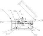
图2示出了本公开实施例用于检测胶囊的数据接收设备的剖视示意图;FIG. 2 shows a schematic cross-sectional view of a data receiving device for detecting a capsule according to an embodiment of the present disclosure;
图3示出了本公开实施例用于检测胶囊的数据接收设备主控制板结构示意图。FIG. 3 shows a schematic structural diagram of a main control board of a data receiving device for detecting capsules according to an embodiment of the present disclosure.
附图标记,如下所示:Reference numbers, as follows:
1、数据接收设备;11、主体;111、容置槽;112、容置腔;113、安装板;114、箱体;115、盖体;116、安装槽;12、接收机构;13、主控制板;131、红外接收管;132、信号处理器;133、单片机;134、存储器;14、充电机构;141、充电驱动板;142、充电线圈;2、检测胶囊。1. Data receiving equipment; 11. Main body; 111, accommodating slot; 112, accommodating cavity; 113, mounting plate; 114, box body; 115, cover body; 116, mounting slot; 12, receiving mechanism; 13, main body control board; 131, infrared receiving tube; 132, signal processor; 133, single chip; 134, memory; 14, charging mechanism; 141, charging drive board; 142, charging coil; 2, detection capsule.
具体实施方式Detailed ways
为使本公开的目的、特征、优点能够更加的明显和易懂,下面将结合本公开实施例中的附图,对本公开实施例中的技术方案进行清楚、完整地描述,显然,所描述的实施例仅仅是本公开一部分实施例,而非全部实施例。基于本公开中的实施例,本领域技术人员在没有做出创造性劳动前提下所获得的所有其他实施例,都属于本公开保护的范围。In order to make the purpose, features and advantages of the present disclosure more obvious and understandable, the technical solutions in the embodiments of the present disclosure will be described clearly and completely below with reference to the accompanying drawings in the embodiments of the present disclosure. The embodiments are only some, but not all, embodiments of the present disclosure. Based on the embodiments in the present disclosure, all other embodiments obtained by those skilled in the art without creative efforts shall fall within the protection scope of the present disclosure.
图1示出了本公开实施例用于检测胶囊的数据接收设备的结构示意图;图2示出了本公开实施例用于检测胶囊的数据接收设备的剖视示意图;请参考图1和图2;Fig. 1 shows a schematic structural diagram of a data receiving device for detecting capsules according to an embodiment of the present disclosure; Fig. 2 shows a schematic cross-sectional view of a data receiving device for detecting capsules according to an embodiment of the present disclosure; please refer to Fig. 1 and Fig. 2 ;
根据本公开的第一方面,提供了一种用于检测胶囊的数据接收设备,设备包括主体11和接收机构12,接收机构12设置在主体11内;主体11上设置有容置槽111,容置槽111用于容置检测胶囊2;接收机构12位于容置槽111的第一方向,接收机构12用于接收来自检测胶囊2的检测数据。According to a first aspect of the present disclosure, a data receiving device for detecting a capsule is provided, the device includes a
本公开的一种检测胶囊的数据接收设备、系统及方法,通过将检测胶囊2放置在数据接收设备1的容置槽111内,通过设备内的接收机构12对容置槽111内的检测胶囊2进行数据读取,从而避免对检测胶囊2的破拆,使检测胶囊2能够循环使用,降低使用成本。A data receiving device, system and method for detecting capsules of the present disclosure, by placing the detecting capsule 2 in the accommodating slot 111 of the data receiving device 1, the detecting capsule in the accommodating slot 111 is detected by the
在本公开实施例中,主体11指的是设备的主要构成部分,具体的,可以包括有箱体114和盖体115,箱体114内形成有容置腔112,容置腔112用于供接收机构12进行安装;其中,接收机构12指的是用于对检测胶囊2发出的信号进行接收的机构,其中,当盖体115盖在箱体114的情况下,盖体115位于容置槽111的第二方向。具体的,检测胶囊2用于放置在指定对象中进行数据采集,其中,指定对象可以是开采地底、海底自然资源或者采取地层等,将检测胶囊2放置在指定对象中进行数据采集,当数据采集完成后,将检测胶囊2取出,放入数据接收设备1中进行数据导出。具体的,因为检测胶囊2体积小,所以检测胶囊2内发出的信号强度范围小,将接收机构12设置在容置槽111的指定距离内;优选的,将检测胶囊2容置在容置槽111内的状态下,检测胶囊2与接收机构12抵接。其中接收机构12位于容置槽111的第一方向,第一方向具体可以是指容置槽111的下方,即容置槽111朝向主体11底部的方向,以使检测胶囊2放置在容置槽111后,在重力的作用下使使检测胶囊2与接收装置抵接。其中,第一方向和第二方向的方向不同,优选的可以是方向相反。提供一个具体实施场景,工作人员将带有检测数据的检测胶囊2放置在容置槽111内,通过工作人员推动和/或检测胶囊2自身的重力作用下,使检测胶囊2与接收机构12抵接,通过接收机构12接收来自监测胶囊的检测数据;当检测结束,通过电脑或上位机对数据接收设备1进行数据读取,从而获得检测数据。In the embodiment of the present disclosure, the
图3示出了本公开实施例用于检测胶囊的数据接收设备主控制板结构示意图,请参考图3;FIG. 3 shows a schematic structural diagram of a main control board of a data receiving device for detecting capsules according to an embodiment of the present disclosure, please refer to FIG. 3 ;
在一可实施方式中,接收机构12包括有主控制板13,主控制板13用于接收来自检测胶囊2的红外信号,并将红外信号转换为检测数据。In an embodiment, the receiving
在本公开实施例中,接收机构12包括有主控制板13,主控制板13是用于对数据接收设备1进行控制操作,包括接收指令、下发指令及数据存储;其中,主控制板13用于接收来自检测胶囊2的红外信号,并将红外信号进行处理后获得检测数据。具体的,主控制板13可以是电路板,电路板上集成有不同功能的处理电路或元件。In the embodiment of the present disclosure, the receiving
在一可实施方式中,主控制板13上设置有红外接收管131,红外接收管131位于容置槽111的下方;当检测胶囊2容置在容置槽111内的情况下,红外接收管131与检测胶囊2的距离小于指定距离;红外接收管131用于接收来自检测胶囊2的红外信号,将红外信号转换为电平脉冲信号。In an embodiment, the
在本公开实施例中,主控制板13上设置有红外接收管131,具体的,红外接收管131为红外线接收二极管,红外接收管131用于接收来自检测胶囊2的红外信号,并将红外信号转换为电平脉冲信号,具体的,检测胶囊2在实现与数据接收装置同步后,根据检测胶囊2内部的时序脉冲,通过红外的形式,将数据一帧一帧的由胶囊发送给设备;具体的,数据0和1分别对应不同的红外调制信号,可实现方式有:红外光较强为1,较弱或无红外为0;或者,红外从强变弱为0,从弱变强为1;因为检测胶囊2的体积小,而且需要满足密封、耐超高压和耐高温的条件,所以内部设置的红外信号发送电路,发射的信号强度弱,需要将红外接收管131设置在容置槽111的指定距离内,以保证当检测胶囊2容置在容置槽111内的情况下,可以通过红外接收管131准确的读取到检测胶囊2发射的红外信号。从而提高信号接收的准确度。In the embodiment of the present disclosure, the
在一可实施方式中,主控制板13上设置有信号处理器132,信号处理器132与红外接收管131通信连接,以接收来自红外接收管131的电平脉冲信号;信号处理器132用于将电平脉冲信号进行整形放大。In an embodiment, the
在本公开实施例中,主控制板13上设置有信号处理器132,信号处理器132可以是信号处理电路,信号处理器132与红外接收管131通信连接,以接收来自红外接收管131的电平脉冲信号;通过信号处理器132对电平脉冲信号进行处理,具体的,可以是对电平脉冲信号进行噪音过滤,获得过滤后的信息;对过滤后的信息进行整形处理;具体的,整形处理是指可以将存在缺陷的脉冲信号进行整形处理,从而获得可供识别的标准脉冲信号。In the embodiment of the present disclosure, the
在一可实施方式中,主控制板13上设置有单片机133,单片机133与信号处理器132连接;单片机133用于将整形放大后的电平脉冲信号进行处理,以获得检测数据;单片机133还连接有存储器134,存储器134用于对检测数据进行存储。In an embodiment, the
在本公开实施例中,主控制板13上设置有单片机133,单片机133是一种集成电路芯片;在本公开中,单片机133用于对整形放大后的电平脉冲信号进行筛选,将其中可识别的电平脉冲信号进行保留,将不可识别的信号进行筛检,从而获得检测数据;单片机133上还设置有存储器134,存储器134用于将检测数据进行存储,其中存储器134可以为快闪存储器134。当数据接收设备1与上位机连接时,将存储器134中的数据传输到上位机中。In the embodiment of the present disclosure, a single-
在一可实施方式中,设备包括充电机构14;充电机构14设置在容置槽111的周向,充电机构14用于为检测胶囊2进行充电,以使检测胶囊2能够发送检测数据。In an embodiment, the device includes a
在本公开实施例中,数据接收设备1设置有充电机构14,充电机构14设置在容置槽111的周向,即容置槽111的四周,当检测胶囊2放置于容置槽111内的情况下,充电机构14用于给检测胶囊2进行充电,以使检测胶囊2的电量能够满足指定电量,以实现向接收机构12发送检测数据;其中,指定电量指的是能够供检测胶囊2完成红外发射的电量。其中,充电机构14可以和主控制板13连接,通过主控制板13控制充电机构14进行充电;也可以是独立设置,通过检测胶囊2放置入容置槽111作为触发条件,触发充电机构14为检测胶囊2进行充电。In the embodiment of the present disclosure, the data receiving device 1 is provided with a
在一可实施方式中,充电机构14包括充电驱动板141和充电线圈142;充电驱动板141设置在主体11内,充电驱动板141与充电线圈142连接;充电线圈142设置在容置槽111的周向;当检测胶囊2容置在容置槽111内的情况下,充电驱动板141用于驱动充电线圈142,以使充电线圈142给检测胶囊2进行充电。In an embodiment, the
在本公开实施例中,充电机构14包括充电驱动板141,充电驱动板141具体可以是无线充电驱动板141,对应的充电线圈142也可以是无线充电线圈142;充电驱动板141设置在主体11内,其位置不作限定;充电线圈142与充电驱动板141连接,充电驱动板141用于驱动充电线圈142,以使充电线圈142开始或停止为检测胶囊2进行充电。其中,充电线圈142环设在容置的周向。当检测胶囊2容置在容置槽111内的情况下,通过充电驱动板141驱动充电线圈142,使充电线圈142给检测胶囊2进行充电;当检测胶囊2离开容置槽111内的情况下,充电驱动板141驱动充电线圈142,停止充电。In the embodiment of the present disclosure, the
在一可实施方式中,主体11包括箱体114和盖体115,箱体114内设置有安装板113;述容置槽111设置在安装板113上;接收机构12设置在箱体114内,接收机构12位于容置槽111的第一方向,第一方向为安装板113朝向箱体114底部的方向;充电机构14设置在箱体114内,充电线圈142设置在安装板113上,充电线圈142设置在容置槽111的周向。In an embodiment, the
在本公开实施例中,箱体114和盖体115的形状不作限定,其中,箱体114上连接有安装板113,安装板113可以是固定设置在箱体114上,也可以是可拆卸的设置在箱体114上;箱体114中形成有容置腔112,具体的,可以是箱体114和安装板113围合形成容置腔112,接收机构12设置在该容置腔112内,进一步,容置槽111开设在安装板113上,具体的,可以开设在安装板113的中央,因为接收机构12设置箱体114和安装板113围合形成容置腔112内,所以接收装置位于安装板113的下方,进一步,位于容置槽111的下方;所以第一方向即为安装板113朝向箱体114底部的方向;进一步的,充电线圈142也设置在安装板113上位于容置槽111周向的位置;其中盖体115盖在箱体114上的情况下,盖体115和安装板113之间形成有供检测胶囊2容置的空间。In the embodiment of the present disclosure, the shapes of the
进一步的,在主控制板13上设置有安装槽116,安装槽116用于安装红外接收管131,使检测胶囊2放置在容置槽111内时,红外接收管131可以与检测胶囊2抵接。Further, an
根据本公开的第二方面,提供了一种数据接收系统,系统包括检测胶囊2和的数据接收设备1;检测胶囊2用于对指定对象进行检测;数据接收设备1用于接收检测胶囊2对指定对象进行检测所获得的检测数据。According to a second aspect of the present disclosure, a data receiving system is provided, the system includes a data receiving device 1 for detecting a capsule 2 and a data receiving device 1; the detecting capsule 2 is used for detecting a specified object; the data receiving device 1 is used for receiving the detection capsule 2 pair. The detection data obtained by the detection of the specified object.
在本公开实施例中,数据接收系统指的是由检测胶囊2和数据接收设备1组合而成的系统;其中,检测胶囊2用于对指定对象进行检测,具体的,指定对象可以是开采地底、海底自然资源或者采取地层等,将检测胶囊2放置在指定对象中进行数据采集,当数据采集完成后,将检测胶囊2取出,放入数据接收设备1中进行数据导出。所以,检测胶囊2需要耐高温、耐超高压以及密封等条件。其中,检测胶囊2内部设置有红外发射电路,当检测胶囊2位于容置槽111内的情况下,红外发射电路用于将检测胶囊2内部的检测数据,通过红外线的形式发送至数据接收设备1。数据接收设备1接收来自检测胶囊2的检测数据。In the embodiment of the present disclosure, the data receiving system refers to a system composed of a detection capsule 2 and a data receiving device 1; wherein, the detection capsule 2 is used to detect a specified object, and specifically, the specified object may be mining underground , seabed natural resources or taking strata, etc., place the detection capsule 2 in the designated object for data collection, when the data collection is completed, take out the detection capsule 2 and put it into the data receiving device 1 for data export. Therefore, the detection capsule 2 needs high temperature resistance, ultra-high pressure resistance and sealing conditions. Wherein, the detection capsule 2 is provided with an infrared emission circuit. When the detection capsule 2 is located in the accommodating slot 111, the infrared emission circuit is used to send the detection data inside the detection capsule 2 to the data receiving device 1 in the form of infrared rays. . The data receiving device 1 receives detection data from the detection capsule 2 .
根据本公开的第三方面,提供了一种数据接收方法,方法包括:将检测胶囊2放置在数据接收设备1的容置槽111内,以使接收机构12位于检测胶囊2的第一方向;数据接收设备1通过接收机构12接收来自检测胶囊2的检测数据,检测数据是检测胶囊2对指定对象进行检测获得。According to a third aspect of the present disclosure, there is provided a data receiving method, the method comprising: placing the detection capsule 2 in the accommodating groove 111 of the data receiving device 1, so that the receiving
在本公开实施例中,将检测胶囊2放置在数据接收设备1的容置槽111内,以使接收机构12位于检测胶囊2的第一方向;数据接收设备1通过充电驱动板141驱动充电线圈142对检测胶囊2进行充电;当检测胶囊2满足指定电量之后,检测胶囊2发送红外同步指令;当数据检测设备接收到红外同步指令,并实现与检测胶囊2同步成功的情况下,通过检测胶囊2向数据接收设备1发送红外信号;红外信号的识别方式可以为,红外光较强为1,较弱或无红外为0;或,红外从强变弱为0,从弱变强为1。数据接收设备1通过红外接收二极管将红外信号变成电平脉冲信号,并将电平脉冲信号发送至处理电路,以对电平脉冲信号进行去噪和整形,输出标准脉冲信号;通过单片机133对标准脉冲信号进行处理,以获得有效数据,根据有效数据确定检测数据;将检测数据存储至主控制板13的存储器134内,以供上位机连接后,进行对存储器134内的数据进行读取。In the embodiment of the present disclosure, the detection capsule 2 is placed in the accommodating slot 111 of the data receiving device 1, so that the receiving
应该理解,可以使用上面所示的各种形式的流程,重新排序、增加或删除步骤。例如,本发公开中记载的各步骤可以并行地执行也可以顺序地执行也可以不同的次序执行,只要能够实现本公开公开的技术方案所期望的结果,本文在此不进行限制。It should be understood that steps may be reordered, added or deleted using the various forms of flow shown above. For example, the steps described in the present disclosure can be executed in parallel, sequentially, or in different orders. As long as the desired results of the technical solutions disclosed in the present disclosure can be achieved, there is no limitation herein.
此外,术语“第一”、“第二”仅用于描述目的,而不能理解为指示或暗示相对重要性或者隐含指明所指示的技术特征的数量。由此,限定有“第一”、“第二”的特征可以明示或隐含地包括至少一个该特征。在本公开的描述中,“多个”的含义是两个或两个以上,除非另有明确具体的限定。In addition, the terms "first" and "second" are only used for descriptive purposes, and should not be construed as indicating or implying relative importance or implying the number of indicated technical features. Thus, a feature delimited with "first", "second" may expressly or implicitly include at least one of that feature. In the description of the present disclosure, "plurality" means two or more, unless expressly and specifically defined otherwise.
以上所述,仅为本公开的具体实施方式,但本公开的保护范围并不局限于此,任何熟悉本技术领域的技术人员在本公开揭露的技术范围内,可轻易想到变化或替换,都应涵盖在本公开的保护范围之内。因此,本公开的保护范围应以所述权利要求的保护范围为准。The above are only specific embodiments of the present disclosure, but the protection scope of the present disclosure is not limited to this. should be included within the scope of protection of the present disclosure. Therefore, the protection scope of the present disclosure should be based on the protection scope of the claims.
Claims (10)
Priority Applications (1)
| Application Number | Priority Date | Filing Date | Title |
|---|---|---|---|
| CN202210125476.2ACN114608637A (en) | 2022-02-10 | 2022-02-10 | A data receiving device, system and method for detecting capsules |
Applications Claiming Priority (1)
| Application Number | Priority Date | Filing Date | Title |
|---|---|---|---|
| CN202210125476.2ACN114608637A (en) | 2022-02-10 | 2022-02-10 | A data receiving device, system and method for detecting capsules |
Publications (1)
| Publication Number | Publication Date |
|---|---|
| CN114608637Atrue CN114608637A (en) | 2022-06-10 |
Family
ID=81858748
Family Applications (1)
| Application Number | Title | Priority Date | Filing Date |
|---|---|---|---|
| CN202210125476.2APendingCN114608637A (en) | 2022-02-10 | 2022-02-10 | A data receiving device, system and method for detecting capsules |
Country Status (1)
| Country | Link |
|---|---|
| CN (1) | CN114608637A (en) |
Citations (14)
| Publication number | Priority date | Publication date | Assignee | Title |
|---|---|---|---|---|
| CN101849814A (en)* | 2010-05-26 | 2010-10-06 | 上海理工大学 | Active Infrared Wireless Capsule Endoscopy System |
| CN202015159U (en)* | 2011-01-28 | 2011-10-26 | 华中科技大学 | Wired data transmission type endoscopie capsulaire system |
| CN104602576A (en)* | 2012-09-07 | 2015-05-06 | 雀巢产品技术援助有限公司 | Capsule storage |
| CN105147227A (en)* | 2015-11-03 | 2015-12-16 | 重庆邮电大学 | Digestive tract lesion detection device and method based on infrared spectrum |
| CN205063932U (en)* | 2015-10-21 | 2016-03-02 | 郑州青林昊晟石油技术开发有限公司 | Sodium chloride logging instrument |
| CN105592772A (en)* | 2013-10-02 | 2016-05-18 | 奥林巴斯株式会社 | Data reception device, capsule endoscope system, data reception method, and program |
| CN106137099A (en)* | 2016-09-27 | 2016-11-23 | 重庆大学 | Intelligent capsule detecting system based on cloud service |
| CN106285626A (en)* | 2016-08-16 | 2017-01-04 | 中煤科工集团重庆研究院有限公司 | Gas emission initial velocity measuring device |
| CN106761534A (en)* | 2017-03-24 | 2017-05-31 | 中国矿业大学 | A kind of coal mine down-hole drilling single rubber bladder sealing device and its method for sealing |
| CN207732847U (en)* | 2017-12-15 | 2018-08-14 | 深圳大学 | A kind of drainpipe detecting capsule apparatus |
| CN108601475A (en)* | 2016-02-05 | 2018-09-28 | 百事可乐公司 | The infrared sensor package detected for ingredient level in beverage dispenser |
| CN215173268U (en)* | 2021-06-10 | 2021-12-14 | 深圳市环水管网科技服务有限公司 | Drainage pipe detects capsule device based on fluid drive |
| CN113834589A (en)* | 2021-08-19 | 2021-12-24 | 中国科学院电工研究所 | Capsule motor rotor temperature measuring device |
| CN215528707U (en)* | 2021-06-21 | 2022-01-14 | 浙江探芯科技有限公司 | Detect wireless charging device of capsule |
- 2022
- 2022-02-10CNCN202210125476.2Apatent/CN114608637A/enactivePending
Patent Citations (14)
| Publication number | Priority date | Publication date | Assignee | Title |
|---|---|---|---|---|
| CN101849814A (en)* | 2010-05-26 | 2010-10-06 | 上海理工大学 | Active Infrared Wireless Capsule Endoscopy System |
| CN202015159U (en)* | 2011-01-28 | 2011-10-26 | 华中科技大学 | Wired data transmission type endoscopie capsulaire system |
| CN104602576A (en)* | 2012-09-07 | 2015-05-06 | 雀巢产品技术援助有限公司 | Capsule storage |
| CN105592772A (en)* | 2013-10-02 | 2016-05-18 | 奥林巴斯株式会社 | Data reception device, capsule endoscope system, data reception method, and program |
| CN205063932U (en)* | 2015-10-21 | 2016-03-02 | 郑州青林昊晟石油技术开发有限公司 | Sodium chloride logging instrument |
| CN105147227A (en)* | 2015-11-03 | 2015-12-16 | 重庆邮电大学 | Digestive tract lesion detection device and method based on infrared spectrum |
| CN108601475A (en)* | 2016-02-05 | 2018-09-28 | 百事可乐公司 | The infrared sensor package detected for ingredient level in beverage dispenser |
| CN106285626A (en)* | 2016-08-16 | 2017-01-04 | 中煤科工集团重庆研究院有限公司 | Gas emission initial velocity measuring device |
| CN106137099A (en)* | 2016-09-27 | 2016-11-23 | 重庆大学 | Intelligent capsule detecting system based on cloud service |
| CN106761534A (en)* | 2017-03-24 | 2017-05-31 | 中国矿业大学 | A kind of coal mine down-hole drilling single rubber bladder sealing device and its method for sealing |
| CN207732847U (en)* | 2017-12-15 | 2018-08-14 | 深圳大学 | A kind of drainpipe detecting capsule apparatus |
| CN215173268U (en)* | 2021-06-10 | 2021-12-14 | 深圳市环水管网科技服务有限公司 | Drainage pipe detects capsule device based on fluid drive |
| CN215528707U (en)* | 2021-06-21 | 2022-01-14 | 浙江探芯科技有限公司 | Detect wireless charging device of capsule |
| CN113834589A (en)* | 2021-08-19 | 2021-12-24 | 中国科学院电工研究所 | Capsule motor rotor temperature measuring device |
Similar Documents
| Publication | Publication Date | Title |
|---|---|---|
| CN104854477B (en) | Land-Based Units for Seismic Data Acquisition | |
| EP0257155B1 (en) | Gun initiation and data recording downhole | |
| CN101798923B (en) | System and method for remote control coal mine evacuation working face advance detection and forecasting | |
| US20190257963A1 (en) | Methods and apparatus for confirmation time break (ctb) determination and shotpoint in-situ recording in seismic electronic detonators | |
| US20210293518A1 (en) | Automatic method and apparatus for logging preprogrammed electronic detonators | |
| CN106464285A (en) | Large-scale sensor network system | |
| US8912896B1 (en) | TPMS setting tool | |
| CN109298266A (en) | Test system, test method, test apparatus, and storage medium | |
| CA3152442A1 (en) | Systems and methods for wireless transmission of power in deep subsurface monitoring | |
| CN114608637A (en) | A data receiving device, system and method for detecting capsules | |
| EP2810796A1 (en) | TPMS setting tool | |
| CN102305065A (en) | Wireless signal transmission method and system for oil and gas wells | |
| CN202100254U (en) | Cableless signal transmission system for oil and gas wells | |
| CN203271732U (en) | Storage type sound wave density-variable logger | |
| US20070094558A1 (en) | Apparatus and method for testing an IEEE1394 port | |
| CN211085491U (en) | Temperature measuring device of capacitor | |
| CN213928342U (en) | Detection device for logging pusher | |
| CN111815824A (en) | An unlocking method based on bluetooth identification | |
| CN203133289U (en) | Data acquisition device for microlog data acquisition and seismic wave excitation apparatus | |
| CN202330706U (en) | Response probability detector | |
| CN115182720A (en) | A borehole imager probe with storage function | |
| CN211474101U (en) | Pump-out logging instrument in-place detection device | |
| CN211047038U (en) | Mining intelligent video camera | |
| CN211295266U (en) | A device for improving battery utilization rate in drilling and transportation construction mode | |
| CN201050364Y (en) | Ground surface wireless read-write type inner-hole electronic measuring device |
Legal Events
| Date | Code | Title | Description |
|---|---|---|---|
| PB01 | Publication | ||
| PB01 | Publication | ||
| SE01 | Entry into force of request for substantive examination | ||
| SE01 | Entry into force of request for substantive examination | ||
| RJ01 | Rejection of invention patent application after publication | Application publication date:20220610 | |
| RJ01 | Rejection of invention patent application after publication |