CN114607239A - A photovoltaic energy-saving liquid flow window - Google Patents
A photovoltaic energy-saving liquid flow windowDownload PDFInfo
- Publication number
- CN114607239A CN114607239ACN202210078845.7ACN202210078845ACN114607239ACN 114607239 ACN114607239 ACN 114607239ACN 202210078845 ACN202210078845 ACN 202210078845ACN 114607239 ACN114607239 ACN 114607239A
- Authority
- CN
- China
- Prior art keywords
- substrate
- photovoltaic
- liquid flow
- sealant
- connecting pipe
- Prior art date
- Legal status (The legal status is an assumption and is not a legal conclusion. Google has not performed a legal analysis and makes no representation as to the accuracy of the status listed.)
- Pending
Links
- 239000007788liquidSubstances0.000titleclaimsabstractdescription45
- 239000000758substrateSubstances0.000claimsabstractdescription127
- 239000012530fluidSubstances0.000claimsabstractdescription43
- 239000005340laminated glassSubstances0.000claimsabstractdescription31
- 239000000565sealantSubstances0.000claimsabstractdescription29
- ATJFFYVFTNAWJD-UHFFFAOYSA-NTinChemical compound[Sn]ATJFFYVFTNAWJD-UHFFFAOYSA-N0.000claimsabstractdescription7
- 239000011521glassSubstances0.000claimsdescription17
- 238000007654immersionMethods0.000claimsdescription14
- 229910021419crystalline siliconInorganic materials0.000claimsdescription11
- 239000000853adhesiveSubstances0.000claimsdescription9
- 230000001070adhesive effectEffects0.000claimsdescription8
- 239000011261inert gasSubstances0.000claimsdescription4
- VGGSQFUCUMXWEO-UHFFFAOYSA-NEtheneChemical compoundC=CVGGSQFUCUMXWEO-UHFFFAOYSA-N0.000claimsdescription3
- 239000005977EthyleneSubstances0.000claimsdescription3
- XTXRWKRVRITETP-UHFFFAOYSA-NVinyl acetateChemical compoundCC(=O)OC=CXTXRWKRVRITETP-UHFFFAOYSA-N0.000claimsdescription3
- 229920001577copolymerPolymers0.000claimsdescription3
- 229910021420polycrystalline siliconInorganic materials0.000claimsdescription3
- 239000005341toughened glassSubstances0.000claimsdescription3
- VVQNEPGJFQJSBK-UHFFFAOYSA-NMethyl methacrylateChemical compoundCOC(=O)C(C)=CVVQNEPGJFQJSBK-UHFFFAOYSA-N0.000claimsdescription2
- 229920005372Plexiglas®Polymers0.000claimsdescription2
- XUIMIQQOPSSXEZ-UHFFFAOYSA-NSiliconChemical compound[Si]XUIMIQQOPSSXEZ-UHFFFAOYSA-N0.000claimsdescription2
- 238000007789sealingMethods0.000claimsdescription2
- 229910052710siliconInorganic materials0.000claimsdescription2
- 239000010703siliconSubstances0.000claimsdescription2
- 239000013078crystalSubstances0.000claims1
- 238000001727in vivoMethods0.000claims1
- 229920005591polysiliconPolymers0.000claims1
- 230000005611electricityEffects0.000abstractdescription8
- 238000006243chemical reactionMethods0.000abstractdescription2
- 239000010409thin filmSubstances0.000description10
- 230000000694effectsEffects0.000description8
- 238000005516engineering processMethods0.000description8
- XLYOFNOQVPJJNP-UHFFFAOYSA-NwaterSubstancesOXLYOFNOQVPJJNP-UHFFFAOYSA-N0.000description8
- 238000010586diagramMethods0.000description7
- 239000011248coating agentSubstances0.000description5
- 238000000576coating methodMethods0.000description5
- 238000009413insulationMethods0.000description5
- 238000004378air conditioningMethods0.000description4
- 238000010248power generationMethods0.000description4
- 230000005855radiationEffects0.000description4
- OKTJSMMVPCPJKN-UHFFFAOYSA-NCarbonChemical compound[C]OKTJSMMVPCPJKN-UHFFFAOYSA-N0.000description3
- 238000010521absorption reactionMethods0.000description3
- 229910052799carbonInorganic materials0.000description3
- 238000005265energy consumptionMethods0.000description3
- 239000010408filmSubstances0.000description3
- 239000007789gasSubstances0.000description3
- 238000009434installationMethods0.000description3
- 230000003993interactionEffects0.000description3
- 238000012546transferMethods0.000description3
- 238000002834transmittanceMethods0.000description3
- 230000000007visual effectEffects0.000description3
- KTSFMFGEAAANTF-UHFFFAOYSA-N[Cu].[Se].[Se].[In]Chemical compound[Cu].[Se].[Se].[In]KTSFMFGEAAANTF-UHFFFAOYSA-N0.000description2
- 230000009471actionEffects0.000description2
- 238000013461designMethods0.000description2
- 229910021421monocrystalline siliconInorganic materials0.000description2
- MARUHZGHZWCEQU-UHFFFAOYSA-N5-phenyl-2h-tetrazoleChemical compoundC1=CC=CC=C1C1=NNN=N1MARUHZGHZWCEQU-UHFFFAOYSA-N0.000description1
- JBRZTFJDHDCESZ-UHFFFAOYSA-NAsGaChemical compound[As]#[Ga]JBRZTFJDHDCESZ-UHFFFAOYSA-N0.000description1
- RYGMFSIKBFXOCR-UHFFFAOYSA-NCopperChemical compound[Cu]RYGMFSIKBFXOCR-UHFFFAOYSA-N0.000description1
- 229920000742CottonPolymers0.000description1
- 229910001218Gallium arsenideInorganic materials0.000description1
- 229910021417amorphous siliconInorganic materials0.000description1
- 230000002528anti-freezeEffects0.000description1
- 230000003796beautyEffects0.000description1
- 230000009286beneficial effectEffects0.000description1
- 238000010276constructionMethods0.000description1
- 229910052802copperInorganic materials0.000description1
- 239000010949copperSubstances0.000description1
- 230000007423decreaseEffects0.000description1
- 230000002542deteriorative effectEffects0.000description1
- 238000011161developmentMethods0.000description1
- 239000012153distilled waterSubstances0.000description1
- 238000005538encapsulationMethods0.000description1
- 238000004134energy conservationMethods0.000description1
- 238000001704evaporationMethods0.000description1
- 239000002803fossil fuelSubstances0.000description1
- 230000017525heat dissipationEffects0.000description1
- 230000010354integrationEffects0.000description1
- 238000010329laser etchingMethods0.000description1
- 239000000463materialSubstances0.000description1
- 238000000034methodMethods0.000description1
- 229910021424microcrystalline siliconInorganic materials0.000description1
- 238000012986modificationMethods0.000description1
- 230000004048modificationEffects0.000description1
- 231100000252nontoxicToxicity0.000description1
- 230000003000nontoxic effectEffects0.000description1
- 150000002894organic compoundsChemical class0.000description1
- 230000009467reductionEffects0.000description1
- 238000013083solar photovoltaic technologyMethods0.000description1
- 230000001131transforming effectEffects0.000description1
Images


Classifications
- E—FIXED CONSTRUCTIONS
- E06—DOORS, WINDOWS, SHUTTERS, OR ROLLER BLINDS IN GENERAL; LADDERS
- E06B—FIXED OR MOVABLE CLOSURES FOR OPENINGS IN BUILDINGS, VEHICLES, FENCES OR LIKE ENCLOSURES IN GENERAL, e.g. DOORS, WINDOWS, BLINDS, GATES
- E06B3/00—Window sashes, door leaves, or like elements for closing wall or like openings; Layout of fixed or moving closures, e.g. windows in wall or like openings; Features of rigidly-mounted outer frames relating to the mounting of wing frames
- E06B3/66—Units comprising two or more parallel glass or like panes permanently secured together
- E06B3/6612—Evacuated glazing units
- E—FIXED CONSTRUCTIONS
- E06—DOORS, WINDOWS, SHUTTERS, OR ROLLER BLINDS IN GENERAL; LADDERS
- E06B—FIXED OR MOVABLE CLOSURES FOR OPENINGS IN BUILDINGS, VEHICLES, FENCES OR LIKE ENCLOSURES IN GENERAL, e.g. DOORS, WINDOWS, BLINDS, GATES
- E06B3/00—Window sashes, door leaves, or like elements for closing wall or like openings; Layout of fixed or moving closures, e.g. windows in wall or like openings; Features of rigidly-mounted outer frames relating to the mounting of wing frames
- E06B3/66—Units comprising two or more parallel glass or like panes permanently secured together
- E06B3/663—Elements for spacing panes
- E06B3/66304—Discrete spacing elements, e.g. for evacuated glazing units
- E—FIXED CONSTRUCTIONS
- E06—DOORS, WINDOWS, SHUTTERS, OR ROLLER BLINDS IN GENERAL; LADDERS
- E06B—FIXED OR MOVABLE CLOSURES FOR OPENINGS IN BUILDINGS, VEHICLES, FENCES OR LIKE ENCLOSURES IN GENERAL, e.g. DOORS, WINDOWS, BLINDS, GATES
- E06B3/00—Window sashes, door leaves, or like elements for closing wall or like openings; Layout of fixed or moving closures, e.g. windows in wall or like openings; Features of rigidly-mounted outer frames relating to the mounting of wing frames
- E06B3/66—Units comprising two or more parallel glass or like panes permanently secured together
- E06B3/677—Evacuating or filling the gap between the panes ; Equilibration of inside and outside pressure; Preventing condensation in the gap between the panes; Cleaning the gap between the panes
- F—MECHANICAL ENGINEERING; LIGHTING; HEATING; WEAPONS; BLASTING
- F24—HEATING; RANGES; VENTILATING
- F24S—SOLAR HEAT COLLECTORS; SOLAR HEAT SYSTEMS
- F24S10/00—Solar heat collectors using working fluids
- F24S10/30—Solar heat collectors using working fluids with means for exchanging heat between two or more working fluids
- F—MECHANICAL ENGINEERING; LIGHTING; HEATING; WEAPONS; BLASTING
- F24—HEATING; RANGES; VENTILATING
- F24S—SOLAR HEAT COLLECTORS; SOLAR HEAT SYSTEMS
- F24S10/00—Solar heat collectors using working fluids
- F24S10/70—Solar heat collectors using working fluids the working fluids being conveyed through tubular absorbing conduits
- H—ELECTRICITY
- H10—SEMICONDUCTOR DEVICES; ELECTRIC SOLID-STATE DEVICES NOT OTHERWISE PROVIDED FOR
- H10F—INORGANIC SEMICONDUCTOR DEVICES SENSITIVE TO INFRARED RADIATION, LIGHT, ELECTROMAGNETIC RADIATION OF SHORTER WAVELENGTH OR CORPUSCULAR RADIATION
- H10F19/00—Integrated devices, or assemblies of multiple devices, comprising at least one photovoltaic cell covered by group H10F10/00, e.g. photovoltaic modules
- H10F19/80—Encapsulations or containers for integrated devices, or assemblies of multiple devices, having photovoltaic cells
- H10F19/804—Materials of encapsulations
- Y—GENERAL TAGGING OF NEW TECHNOLOGICAL DEVELOPMENTS; GENERAL TAGGING OF CROSS-SECTIONAL TECHNOLOGIES SPANNING OVER SEVERAL SECTIONS OF THE IPC; TECHNICAL SUBJECTS COVERED BY FORMER USPC CROSS-REFERENCE ART COLLECTIONS [XRACs] AND DIGESTS
- Y02—TECHNOLOGIES OR APPLICATIONS FOR MITIGATION OR ADAPTATION AGAINST CLIMATE CHANGE
- Y02E—REDUCTION OF GREENHOUSE GAS [GHG] EMISSIONS, RELATED TO ENERGY GENERATION, TRANSMISSION OR DISTRIBUTION
- Y02E10/00—Energy generation through renewable energy sources
- Y02E10/40—Solar thermal energy, e.g. solar towers
- Y02E10/44—Heat exchange systems
- Y—GENERAL TAGGING OF NEW TECHNOLOGICAL DEVELOPMENTS; GENERAL TAGGING OF CROSS-SECTIONAL TECHNOLOGIES SPANNING OVER SEVERAL SECTIONS OF THE IPC; TECHNICAL SUBJECTS COVERED BY FORMER USPC CROSS-REFERENCE ART COLLECTIONS [XRACs] AND DIGESTS
- Y02—TECHNOLOGIES OR APPLICATIONS FOR MITIGATION OR ADAPTATION AGAINST CLIMATE CHANGE
- Y02E—REDUCTION OF GREENHOUSE GAS [GHG] EMISSIONS, RELATED TO ENERGY GENERATION, TRANSMISSION OR DISTRIBUTION
- Y02E10/00—Energy generation through renewable energy sources
- Y02E10/50—Photovoltaic [PV] energy
Landscapes
- Engineering & Computer Science (AREA)
- Civil Engineering (AREA)
- Structural Engineering (AREA)
- Physics & Mathematics (AREA)
- Life Sciences & Earth Sciences (AREA)
- Sustainable Development (AREA)
- Sustainable Energy (AREA)
- Thermal Sciences (AREA)
- Chemical & Material Sciences (AREA)
- Combustion & Propulsion (AREA)
- Mechanical Engineering (AREA)
- General Engineering & Computer Science (AREA)
- Photovoltaic Devices (AREA)
Abstract
Translated fromChinese
Description
Translated fromChinese技术领域technical field
本发明涉及太阳能利用式建筑节能围护结构技术领域,具体地,是关于半透明光伏夹层玻璃与液流窗相结合的一种光伏节能液流窗。The invention relates to the technical field of a solar energy utilization type building energy-saving enclosure structure, in particular to a photovoltaic energy-saving liquid flow window which is combined with a translucent photovoltaic laminated glass and a liquid flow window.
技术背景technical background
在建筑中利用太阳能,包括太阳能的光热利用、太阳能的光电利用等方式可以全部或部分代替化石燃料,并减少碳排放,通过转变建筑内的能源结构实现节能降碳。The utilization of solar energy in buildings, including solar thermal utilization and photovoltaic utilization of solar energy, can completely or partially replace fossil fuels, reduce carbon emissions, and achieve energy conservation and carbon reduction by transforming the energy structure in buildings.
液流窗是一种可吸收并利用太阳能热能的新型节能窗体。在不影响建筑美观的情况下,充分利用现代建筑中大规模的建筑外窗面积,无需额外的安装场地。在建筑中利用太阳能转化成的热能,降低建筑内热水系统能耗;并降低房间得热,从而降低房间夏季空调系统的能耗;同时减少返回室外环境的热量,缓解城市的热岛效应。但是到目前为止,在液流窗内使用最广泛的第一基板和第二基板是玻璃,第一流体是无色无毒的蒸馏水,其综合太阳能吸收率非常低,因此导致整个窗体对太阳能的热利用效率不高,而且无法实现对太阳能的电利用。Liquid flow window is a new type of energy-saving window that can absorb and utilize solar thermal energy. Without affecting the beauty of the building, it can make full use of the large-scale building exterior window area in modern buildings, and no additional installation site is required. The heat energy converted from solar energy is used in buildings to reduce the energy consumption of the hot water system in the building; and the heat gain of the room is reduced, thereby reducing the energy consumption of the air conditioning system in the room in summer; at the same time, the heat returned to the outdoor environment is reduced, and the urban heat island effect is alleviated. But so far, the most widely used first and second substrates in the liquid flow window are glass, the first fluid is colorless and non-toxic distilled water, and its comprehensive solar energy absorption rate is very low, thus causing the entire window to be resistant to solar energy. The heat utilization efficiency is not high, and the electric utilization of solar energy cannot be realized.
发明内容SUMMARY OF THE INVENTION
鉴于以上背景技术,本发明将半透明光伏窗技术与液流窗技术结合,提出一种半透明光伏夹层玻璃与液流窗相结合的一种光伏节能液流窗。该光伏节能液流窗采纳了现有液流窗技术实现太阳能光热利用以及半透明光伏夹层玻璃实现太阳能光电利用的优点,同时又规避了现阶段液流窗技术太阳能吸收率较低和半透明光伏夹层玻璃中常用的晶体硅光伏电池的光电转化效率随电池温度的升高而降低的缺点。In view of the above background technology, the present invention combines the semi-transparent photovoltaic window technology with the liquid flow window technology, and proposes a photovoltaic energy-saving flow window combining the semi-transparent photovoltaic laminated glass and the liquid flow window. The photovoltaic energy-saving liquid flow window adopts the advantages of the existing liquid flow window technology to realize solar thermal utilization and semi-transparent photovoltaic laminated glass to realize solar photovoltaic utilization, and at the same time avoids the low solar absorption rate and translucency of the current liquid flow window technology. The disadvantage of the photoelectric conversion efficiency of crystalline silicon photovoltaic cells commonly used in photovoltaic laminated glass decreases with the increase of cell temperature.
为实现上述目的,本发明提供如下技术方案:一种光伏节能液流窗,包括In order to achieve the above purpose, the present invention provides the following technical solutions: a photovoltaic energy-saving liquid flow window, comprising:
第一基板和第二基板,固定窗框,第一基板和第二基板相对设置于固定窗框中,间距为10–100mm;The first base plate and the second base plate are fixed to the window frame, and the first base plate and the second base plate are oppositely arranged on the fixed window frame with a distance of 10-100mm;
密封胶,设置于第一基板和第二基板之间四周区域,密封胶与第一基板及第二基板围合形成第一密闭空腔,第一密闭空腔内设有第一流体;The sealant is arranged in the surrounding area between the first substrate and the second substrate, the sealant is enclosed with the first substrate and the second substrate to form a first airtight cavity, and the first airtight cavity is provided with a first fluid;
第一基板或第二基板为半透明光伏夹层玻璃,半透明光伏夹层玻璃,包括盖板,胶粘剂和太阳能电池片;在固定窗框内设有光伏接线盒,光伏接线盒中的电极与通过涂锡带引出的半透明光伏夹层玻璃内的太阳能电池片的电极相连。The first substrate or the second substrate is a semi-transparent photovoltaic laminated glass, including a cover plate, an adhesive and a solar cell; a photovoltaic junction box is arranged in the fixed window frame, and the electrodes in the photovoltaic junction box are connected to each other through coating. The electrodes of the solar cells in the semi-transparent photovoltaic laminated glass drawn by the tin tape are connected.
作为优选的技术实施方案,半透明光伏夹层玻璃内部的太阳能电池片为晶体硅太阳能电池,晶体硅太阳能电池为单晶硅电池或多晶硅电池。As a preferred technical embodiment, the solar cell inside the translucent photovoltaic laminated glass is a crystalline silicon solar cell, and the crystalline silicon solar cell is a monocrystalline silicon cell or a polycrystalline silicon cell.
作为优选的技术实施方案,盖板为钢化玻璃或有机玻璃。As a preferred technical embodiment, the cover plate is tempered glass or organic glass.
作为优选的技术实施方案,胶粘剂为乙烯和醋酸乙烯酯的共聚物。As a preferred technical embodiment, the adhesive is a copolymer of ethylene and vinyl acetate.
作为优选的技术实施方案,第一基板或第二基板为普通玻璃或真空玻璃或中空玻璃;在真空玻璃中设有支撑柱。As a preferred technical embodiment, the first substrate or the second substrate is ordinary glass or vacuum glass or insulating glass; a support column is provided in the vacuum glass.
作为优选的技术实施方案,密封胶内设有浸没式换热器,浸没式换热器的一侧浸没于第一流体内,在浸没式换热器内通过呈单向流动的第二流体,第一流体和第二流体通过浸没式换热器实现换热。As a preferred technical embodiment, the sealant is provided with an immersion heat exchanger, one side of the immersion heat exchanger is immersed in the first fluid, and the second fluid flowing in one direction passes through the immersion heat exchanger, and the first fluid is immersed in the first fluid. Heat exchange between the first fluid and the second fluid is achieved through an immersion heat exchanger.
作为优选的技术实施方案,浸没式换热器包括设置于第一密闭空腔外的入口侧水平连接管和出口侧水平连接管、入口侧竖直连接管和出口侧竖直连接管以及设置于第一密闭空腔内的主体换热水平管;入口侧竖直连接管和出口侧竖直连接管分别穿过密封胶的第一开孔和第二开孔;入口侧竖直连接管和出口侧竖直连接管的外端分别连通入口侧水平连接管和出口侧水平连接管,入口侧竖直连接管和出口侧竖直连接管的内端分别连通主体换热水平管的两端。As a preferred technical embodiment, the submerged heat exchanger includes an inlet-side horizontal connecting pipe and an outlet-side horizontal connecting pipe, an inlet-side vertical connecting pipe and an outlet-side vertical connecting pipe arranged outside the first closed cavity, and a The main body heat exchange horizontal pipe in the first airtight cavity; the vertical connecting pipe on the inlet side and the vertical connecting pipe on the outlet side pass through the first opening and the second opening of the sealant respectively; the vertical connecting pipe on the inlet side and the outlet The outer ends of the side vertical connection pipes are respectively connected with the inlet side horizontal connection pipes and the outlet side horizontal connection pipes, and the inner ends of the inlet side vertical connection pipes and the outlet side vertical connection pipes are respectively connected with both ends of the main body heat exchange horizontal pipes.
作为优选的技术实施方案,第一流体的液位线位于浸没式换热器的主体换热水平管之上。As a preferred technical embodiment, the liquid level line of the first fluid is located above the main body heat exchange horizontal pipe of the submerged heat exchanger.
作为优选的技术实施方案,密封胶上部还设有第三开孔,第三开孔上设有可拆卸的密封塞。As a preferred technical embodiment, the upper part of the sealant is further provided with a third opening, and the third opening is provided with a detachable sealing plug.
本发明还提出了一种光伏节能液流窗,包括The present invention also provides a photovoltaic energy-saving liquid flow window, comprising:
第一基板、第二基板、第三基板和第四基板,固定窗框,第一基板和第二基板相对设置于固定窗框中,间距为10–100mm;The first substrate, the second substrate, the third substrate and the fourth substrate are fixed to the window frame, and the first substrate and the second substrate are oppositely arranged on the fixed window frame with a distance of 10-100mm;
密封胶,设置于第一基板和第二基板,第二基板和第三基板,第三基板和第四基板之间四周区域,密封胶与第一基板及第二基板围合形成第一密闭空腔,第一密闭空腔内设有第一流体;The sealant is arranged on the first substrate and the second substrate, the second substrate and the third substrate, and the surrounding area between the third substrate and the fourth substrate, and the sealant is enclosed with the first substrate and the second substrate to form a first airtight space a cavity, the first closed cavity is provided with a first fluid;
第一基板或第二基板为半透明光伏夹层玻璃,半透明光伏夹层玻璃,包括盖板,胶粘剂和太阳能电池片;在固定窗框内设有光伏接线盒,光伏接线盒中的电极与通过涂锡带引出的半透明光伏夹层玻璃内的太阳能电池片的电极相连;The first substrate or the second substrate is a semi-transparent photovoltaic laminated glass, including a cover plate, an adhesive and a solar cell; a photovoltaic junction box is arranged in the fixed window frame, and the electrodes in the photovoltaic junction box are connected to each other through coating. The electrodes of the solar cells in the semi-transparent photovoltaic laminated glass drawn by the tin tape are connected;
第二基板和第三基板相对设置于固定窗框中,与密封胶围合形成第二密闭空腔,在第二密闭空腔内填充空气或惰性气体或维持真空状态;The second substrate and the third substrate are oppositely arranged on the fixed window frame, and are enclosed with the sealant to form a second airtight cavity, and the second airtight cavity is filled with air or inert gas or maintained in a vacuum state;
第三基板和第四基板相对设置于固定窗框中,与密封胶围合形成第三密闭空腔,第三密闭空腔内通过第二流体。The third substrate and the fourth substrate are oppositely arranged on the fixed window frame, and are enclosed with the sealant to form a third airtight cavity, and the second fluid passes through the third airtight cavity.
其中,第一基板和/或第二基板和/或第三基板和/或第四基板可进行镀膜,如low-e镀膜,提升窗体的节能性;如减反射薄膜,降低反射太阳光造成的城市光污染。Wherein, the first substrate and/or the second substrate and/or the third substrate and/or the fourth substrate can be coated, such as low-e coating, to improve the energy saving of the window; such as an anti-reflection film, to reduce the effect of reflected sunlight city light pollution.
本发明相对现有技术取得的有益效果为:(1)将半透明太阳能光伏技术与液流窗技术相结合,同时实现对太阳能的电利用和热利用,提升窗体综合利用率。对液流窗而言,其太阳能吸收率得到提升,太阳能热利用能力增强;对晶体硅光伏电池而言,其温度降低,太阳能电利用能力增强。(2)太阳能电利用率不低于10%,太阳能热利用率不低于15%,因此本专利窗户的太阳能综合利用率不低于25%。实现建筑内空调系统和热水系统的节能,为建筑内照明系统和空调系统等提供电能,并缓解城市的热岛效应。本发明提供一种光伏节能液流窗,可应用于新建建筑和改建建筑,推动太阳能与建筑一体化技术的发展。Compared with the prior art, the present invention has the following beneficial effects: (1) Combines the semi-transparent solar photovoltaic technology with the liquid flow window technology, realizes the electric and thermal utilization of solar energy at the same time, and improves the comprehensive utilization rate of the window. For the liquid flow window, its solar absorption rate is improved, and the solar thermal utilization capacity is enhanced; for the crystalline silicon photovoltaic cell, its temperature is lowered, and the solar power utilization capacity is enhanced. (2) The utilization rate of solar electricity is not less than 10%, and the utilization rate of solar heat is not less than 15%, so the comprehensive utilization rate of solar energy of the patented window is not less than 25%. Realize the energy saving of the air-conditioning system and hot water system in the building, provide electricity for the lighting system and air-conditioning system in the building, and alleviate the urban heat island effect. The invention provides a photovoltaic energy-saving liquid flow window, which can be applied to new buildings and rebuilt buildings, and promotes the development of solar energy and building integration technology.
附图说明Description of drawings
为了更清楚地说明本发明内容,下面结合附图和实施例对本发明进一步说明。In order to illustrate the content of the present invention more clearly, the present invention will be further described below with reference to the accompanying drawings and embodiments.
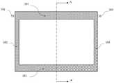
图1为本发明实施例1和实施例2提供的一种光伏节能液流窗的正视图;1 is a front view of a photovoltaic energy-saving liquid flow window provided in Embodiment 1 and Embodiment 2 of the present invention;
图2为本发明实施例1提供的一种光伏节能液流窗沿剖线A-A`的剖面结构示意图;2 is a schematic cross-sectional structure diagram of a photovoltaic energy-saving liquid flow window along section line A-A' provided in Embodiment 1 of the present invention;
图3为本发明实施例1提供的一种光伏节能液流窗的结构示意图;3 is a schematic structural diagram of a photovoltaic energy-saving liquid flow window provided in Embodiment 1 of the present invention;
图4为本发明实施例1提供的一种含中空设计的光伏节能液流窗结构示意图;4 is a schematic structural diagram of a photovoltaic energy-saving liquid flow window with a hollow design provided in Embodiment 1 of the present invention;
图5为本发明实施例1提供的一种含真空设计的光伏节能液流窗结构示意图;5 is a schematic structural diagram of a photovoltaic energy-saving liquid flow window with a vacuum design provided in Embodiment 1 of the present invention;
图6为本发明实施例1和实施例2提供的一种光伏节能液流窗的浸没式换热器的安装示意图;6 is a schematic diagram of the installation of an immersed heat exchanger of a photovoltaic energy-saving liquid flow window provided in Embodiments 1 and 2 of the present invention;
图7为本发明实施例2提供的一种光伏节能液流窗沿剖线A-A`的剖面结构示意图。7 is a schematic cross-sectional structure diagram of a photovoltaic energy-saving liquid flow window along the section line A-A' according to Embodiment 2 of the present invention.
附图标记说明:Description of reference numbers:
101-第一窗框;102-第二窗框;103-第三窗框;104-第四窗框;201-第一基板;202-第一密闭空腔;203-第一流体;204-第二基板;205-密封胶;206-第二流体;207-第一开孔;208-第二开孔;209-第三开孔;210-液位线;211-软塞;212-第二密闭空腔;213-第三基板;214-第三密闭空腔;215-第四基板;300-浸没式换热器;301-水平连接管;302- 竖直连接管;303-水平管;304-竖直连接管;305-水平连接管;306-第一固定圈;307-第二固定圈;401-光伏接线盒;402-第一盖板;403-胶粘剂;404-太阳能电池片;405-第二盖板;406-气体层;407-真空层;408-支撑柱。101-first window frame; 102-second window frame; 103-third window frame; 104-fourth window frame; 201-first substrate; 202-first closed cavity; 203-first fluid; 204- 205-sealant; 206-second fluid; 207-first opening; 208-second opening; 209-third opening; 210-liquid level line; 211-soft plug; 212-first Two closed cavity; 213-third base plate; 214-third closed cavity; 215-fourth base plate; 300-submerged heat exchanger; 301-horizontal connecting pipe; 302-vertical connecting pipe; 303-horizontal pipe 304-vertical connecting pipe; 305-horizontal connecting pipe; 306-first fixing ring; 307-second fixing ring; 401-photovoltaic junction box; 402-first cover; 403-adhesive; 404-solar cell sheet 405-second cover plate; 406-gas layer; 407-vacuum layer; 408-support column.
具体实施方式Detailed ways
为使本发明的目的、技术方案和优点更加清楚,下面将结合本发明附图及实施例对技术方案进行清楚、完整地描述。In order to make the objectives, technical solutions and advantages of the present invention clearer, the technical solutions will be clearly and completely described below with reference to the accompanying drawings and embodiments of the present invention.
在本发明的描述中,需要理解的是,术语“上”“下”“左”“右”等指示的方位或位置关系为基于附图所示的方位或位置关系,或者是本发明产品使用时惯常摆放的方位或位置关系,或者是本领域技术人员惯常理解的方位或位置关系,仅是为了便于描述本发明和简化描述,而不是指示或暗示所指的设备或元件必须具有特定的方位、以特定的方位构造和操作,因此不能理解为对本发明的限制。In the description of the present invention, it should be understood that the orientation or positional relationship indicated by the terms "up", "down", "left", "right", etc. is based on the orientation or positional relationship shown in the accompanying drawings, or the use of the product of the present invention. The orientation or positional relationship that is usually placed at times, or the orientation or positional relationship that is commonly understood by those skilled in the art, is only for the convenience of describing the present invention and simplifying the description, rather than indicating or implying that the referred device or element must have a specific Orientation, construction and operation in a particular orientation, and therefore should not be construed as limiting the invention.
本发明的“第一”、“第二”等,仅仅用于在描述上加以区分,并没有特殊的含义。In the present invention, "first", "second", etc. are only used for distinction in description, and have no special meaning.
实施例1Example 1
如图1-2所示,提供一种光伏节能液流窗,包括第一基板201和第二基板204,第一基板 201和第二基板204相对设置,还包括固定窗框,用于固定第一基板201和第二基板204;固定窗框通常由四个窗框边组成,包括位于上侧的第一窗框101,位于左侧的第二窗框102,位于下侧的第三窗框103和位于右侧的第四窗框104。As shown in FIG. 1-2, a photovoltaic energy-saving liquid flow window is provided, including a
包括密封胶205,设置于所述第一基板201和第二基板204之间四周区域,密封胶205与第一基板201及第二基板204围合形成第一密闭空腔202,第一基板201和第二基板204之间的间距即第一密闭空腔202的厚度为10–100mm,第一密闭空腔202内设有第一流体203。It includes a
优选的,第一基板201或第二基板204为半透明光伏夹层玻璃,在第三窗框103内设有光伏接线盒401,光伏接线盒401中的电极连线与通过涂锡带引出的半透明光伏夹层玻璃内的太阳能电池片的电极相连。Preferably, the
如图3所示,本实施例中第一基板201为半透明光伏夹层玻璃,采用通用的半透明光伏夹层玻璃的封装方式,其结构依次是第一盖板402、胶粘剂403、太阳能电池片404、胶粘剂403、第二盖板405。其中,第一盖板402和第二盖板405为钢化玻璃或有机玻璃,胶粘剂403为EVA (乙烯和醋酸乙烯酯的共聚物)。As shown in FIG. 3 , in this embodiment, the
如图4所示,优选的,当在需要保温隔热的环境中使用时,第二基板204为中空玻璃或真空玻璃,选用中空玻璃时,气体层406可以保持空气状态,也可以充入惰性气体。As shown in FIG. 4 , preferably, when used in an environment requiring thermal insulation, the
如图5所示,优选的,当选用真空玻璃时,为了抵抗负压,在真空层407内还设有真空支撑柱408。As shown in FIG. 5 , preferably, when vacuum glass is used, in order to resist negative pressure, a
在通常环境下使用时,第二基板204可以选用普通玻璃。When used in a normal environment, the
如图3-5所示,半透明光伏夹层玻璃的太阳能电池片为晶体硅太阳能电池、薄膜太阳能电池、异质结太阳能电池、硅基柔性薄膜电池、钙钛矿太阳能电池等。As shown in Figure 3-5, the solar cells of translucent photovoltaic laminated glass are crystalline silicon solar cells, thin-film solar cells, heterojunction solar cells, silicon-based flexible thin-film cells, perovskite solar cells, etc.
其中,优选的,晶体硅太阳能电池可选用单晶硅电池或多晶硅电池,通过利用激光刻蚀等技术实现所述的半透明第一基板201对可见光的透过率;Wherein, preferably, a single crystal silicon cell or a polycrystalline silicon cell can be selected for the crystalline silicon solar cell, and the transmittance of the translucent
薄膜太阳能电池可选用非晶硅薄膜电池、微晶硅薄膜电池、碲化镉薄膜电池、砷化镓薄膜电池、铜铟硒薄膜电池、铜铟镓硒薄膜电池、染料敏化薄膜电池、有机化合物电池等。Thin film solar cells can choose amorphous silicon thin film batteries, microcrystalline silicon thin film batteries, cadmium telluride thin film batteries, gallium arsenide thin film batteries, copper indium selenide thin film batteries, copper indium gallium selenide thin film batteries, dye-sensitized thin film batteries, organic compounds battery etc.
本实施例中,在第三窗框103内设有的光伏接线盒401将太阳能电池片404互联后产生的电力与外部线路连接,实现发电和供电效果。In this embodiment, the
如6所示,优选的,提供一种光伏节能液流窗中含有的浸没式换热器300的安装示意图。按照顺序包括入口侧的水平连接管301,入口侧的竖直连接管302,主体换热水平管303,出口侧的竖直连接管304和出口侧的水平连接管305。其中,入口侧的水平连接管301和出口侧的水平连接管305可采用保温棉进行适度保温,防止热损失。整个浸没式换热器300可采用铜等导热系数较高的材料制作,其中主体换热水平管303的两侧可采用环形肋片设计,加强换热。As shown in 6, preferably, an installation schematic diagram of the immersed
优选的,第一窗框101以及周围区域的密封胶205上设有3个开孔,分别是第一开孔207 用于通过浸没式换热器300的入口侧的竖直连接管302,第二开孔208用于通过浸没式换热器 300的出口侧的竖直连接管304,第三开孔209用于利用虹吸效应对第一密闭空腔202进行充/ 放第一流体203。其中,第三开孔209用软塞211密封,保持常闭状态,防止第一流体203蒸发或氧化变质。通过在入口侧的竖直连接管302和出口侧的竖直连接管304上使用上端的第一固定圈306和下端的第二固定圈307,使整个浸没式换热器300固定于第一窗框101。Preferably, the
浸没式换热300的主体换热水平管303和部分入口侧的竖直连接管302及部分出口侧的竖直连接管304浸没在位于第一密闭空腔202的第一流体203内。第一密闭空腔202内第一流体 203的液位线210总是没过浸没式换热器300的主体换热水平管303,防止传热恶化。同时,浸没式换热器300完全被第一窗框101遮挡,不影响美观和视野交互。The main body heat exchange
浸没式换热器300内设有第二流体206,浸没式换热器300一侧浸没于第一流体203中,第一流体203可以是水、防冻液或纳米流体等可以增强传热的流体;或是特定颜色的稳定的染料溶液,满足用户对幕墙外观审美的需求。浸没式换热器300另一侧的第二流体206可以是建筑内的市政供水或其他温度低于第一流体203的流体。第一流体203在太阳辐射作用下温度升高,在第一密闭空腔202内沿温度较高的第一基板201向上流动,到达位于第一密闭空腔202 的浸没式换热器300一侧进行放热,降温后的第一流体203沿着温度较低的第二基板204向下流动,整体因此呈自然环形流动;所述第二流体206在浸没式换热器300内呈单向流动。第二流体206主要在浸没式换热器300的主体换热水平管303内进行换热,通过吸收第一流体203 的热量,自身温度提升,流经管道连接到集热装置。The submerged
本实施例中,提出的一种光伏节能液流窗,可以通过对太阳能的热利用和电利用,在发电的同时实现建筑内空调系统、热水系统、照明系统等的节能,可以用于各种气候环境下。在室外温度高于某一用户设定温度时,如在夏季,本发明光伏液流窗的半透明光伏夹层玻璃部分,利用其不透明(或半透明)的光伏电池通过光伏效应发电,主动将部分太阳辐射转变为高品位的电能,而透明(或半透明)部分则实现室内自然采光以及室内外的视觉交互。当第一基板 201选用的半透明光伏夹层玻璃内的太阳能电池片404是晶体硅时,随着温度的变化其发电效率也会受到影响,而第一密闭空腔202内的第一流体203的循环,可以有效降低太阳能电池片 404的温度,提升了窗体的发电效率。而且第一流体203通过直接的太阳辐射和间接的基板传热两种方式得到热量,加热第二液体206,实现了太阳能热利用,对建筑内的热水系统起到了预热的作用,降低了建筑内热水系统的能耗及相应的碳排放。In this embodiment, a photovoltaic energy-saving liquid flow window is proposed, which can realize the energy saving of the air-conditioning system, hot water system, lighting system, etc. in the building while generating electricity through the thermal utilization and electricity utilization of solar energy, and can be used in various in a climatic environment. When the outdoor temperature is higher than a certain user-set temperature, such as in summer, the semi-transparent photovoltaic laminated glass part of the photovoltaic liquid flow window of the present invention utilizes its opaque (or semi-transparent) photovoltaic cells to generate electricity through the photovoltaic effect, and actively converts the partial The solar radiation is converted into high-grade electricity, while the transparent (or translucent) part enables natural lighting in the room and visual interaction between indoor and outdoor. When the
当户外温度低于某一设定温度时,如在冬天,同样的,本发明光伏液流窗的半透明光伏夹层玻璃内的太阳能电池片404可以通过光伏效应发电,主动将部分太阳辐射转变为高品位的电能,而透明(或半透明)部分则实现室内自然采光以及室内外的视觉交互。为减少室内散热,一种可行的操作为移开软塞211,使第一密闭空腔202内的第一流体203在虹吸作用下从第一窗框101密封胶内设有的第三开孔209处排出,利用第一密闭空腔202内的空气层实现建筑的保温。特别地,可在第一密闭空腔202内充入惰性气体,进一步提升窗体在寒冷情况下的保温能力,降低通过建筑窗体的热损失。此时,本发明提到的一种光伏节能液流窗转换为一种半透明光伏与中空窗相结合的新型节能多层玻璃窗,实现建筑保温和发电。When the outdoor temperature is lower than a certain set temperature, such as in winter, similarly, the
进一步的,当半透明光伏夹层玻璃中的电池片为晶体硅太阳能电池时,可以通过改变电池片的排列间隙,调节透光率。Further, when the cells in the translucent photovoltaic laminated glass are crystalline silicon solar cells, the light transmittance can be adjusted by changing the arrangement gap of the cells.
其中,第一基板和/或第二基板可进行镀膜,如low-e镀膜,提升窗体的节能性;如减反射薄膜,降低反射太阳光造成的城市光污染。Wherein, the first substrate and/or the second substrate can be coated, such as low-e coating, to improve the energy saving of the window; such as an anti-reflection film, to reduce urban light pollution caused by reflected sunlight.
实施例2Example 2
如图1和图7所示,提供一种光伏节能液流窗,包括第一基板201、第二基板204、第三基板213和第四基板215,第一基板201和第二基板204相对设置;还包括固定窗框,用于固定第一基板201、第二基板204、第三基板213和第四基板215;固定窗框通常由四个窗框边组成,包括位于上侧的第一窗框101,位于左侧的第二窗框102,位于下侧的第三窗框103和位于右侧的第四窗框104。As shown in FIG. 1 and FIG. 7 , a photovoltaic energy-saving liquid flow window is provided, including a
包括密封胶205,设置于所述第一基板201和第二基板204,第二基板204和第三基板213,第三基板213和第四基板215之间四周区域,密封胶与第一基板及第二基板围合形成第一密闭空腔202,第一密闭空腔202的厚度即第一基板201和第二基板204之间的间距为10–100mm,第一密闭空腔202内设有第一流体203。Including a
优选的,第一基板201或第二基板204为半透明光伏夹层玻璃,本实施例中第一基板201 为半透明光伏夹层玻璃,在第三窗框103内设有光伏接线盒401,光伏接线盒401中的电极连线与通过涂锡带引出的半透明光伏夹层玻璃内的太阳能电池片的电极相连。Preferably, the
第二基板204和第三基板213相对设置于固定窗框中,与密封胶205围合形成第二密闭空腔212,在第二密闭空腔212内填充空气或惰性气体或维持真空状态;The
第三基板213和第四基板215相对设置于固定窗框中,与密封胶205围合形成第三密闭空腔214,第三密闭空腔214内通过第二流体。The
优选的,在第一密闭空腔202或第三密闭空腔214中还可以设有浸没式换热器300。Preferably, a submerged
进一步的,当半透明光伏夹层玻璃中的电池片为晶体硅太阳能电池时,可以通过改变电池片的排列间隙,调节透光率。Further, when the cells in the translucent photovoltaic laminated glass are crystalline silicon solar cells, the light transmittance can be adjusted by changing the arrangement gap of the cells.
其中,第一基板和/或第二基板和/或第三基板和/或第四基板可进行镀膜,如low-e镀膜,提升窗体的节能性;如减反射薄膜,降低反射太阳光造成的城市光污染。Wherein, the first substrate and/or the second substrate and/or the third substrate and/or the fourth substrate can be coated, such as low-e coating, to improve the energy saving of the window; such as an anti-reflection film, to reduce the effect of reflected sunlight city light pollution.
无需进一步详细说明,相信本领域技术人员可以使用本文描述最大程度地利用本发明。这里所描述的实施例应被解释为说明性的,而不是以任何方式限制本发明的其余部分。虽然已经示出和描述了实施例,但是本领域技术人员可以在不脱离本发明的精神和教导的情况下对其进行许多变化和修改。因此,保护范围不受上述说明的限制,而是仅受专利要求的限制,包括专利要求主题的所有等同物。Without further elaboration, it is believed that one skilled in the art can, using the description herein, utilize the present invention to its fullest extent. The embodiments described herein are to be construed as illustrative and not in any way limiting to the remainder of the invention. Although embodiments have been shown and described, many changes and modifications can be made thereto by those skilled in the art without departing from the spirit and teachings of this invention. Accordingly, the scope of protection is not limited by the foregoing description, but only by the patent claims, including all equivalents of the subject matter of the patent claims.
Claims (10)
Translated fromChinesePriority Applications (1)
| Application Number | Priority Date | Filing Date | Title |
|---|---|---|---|
| CN202210078845.7ACN114607239A (en) | 2022-01-24 | 2022-01-24 | A photovoltaic energy-saving liquid flow window |
Applications Claiming Priority (1)
| Application Number | Priority Date | Filing Date | Title |
|---|---|---|---|
| CN202210078845.7ACN114607239A (en) | 2022-01-24 | 2022-01-24 | A photovoltaic energy-saving liquid flow window |
Publications (1)
| Publication Number | Publication Date |
|---|---|
| CN114607239Atrue CN114607239A (en) | 2022-06-10 |
Family
ID=81857955
Family Applications (1)
| Application Number | Title | Priority Date | Filing Date |
|---|---|---|---|
| CN202210078845.7APendingCN114607239A (en) | 2022-01-24 | 2022-01-24 | A photovoltaic energy-saving liquid flow window |
Country Status (1)
| Country | Link |
|---|---|
| CN (1) | CN114607239A (en) |
Cited By (2)
| Publication number | Priority date | Publication date | Assignee | Title |
|---|---|---|---|---|
| CN115450546A (en)* | 2022-08-15 | 2022-12-09 | 北京科技大学 | A liquid flow window with air purification function |
| CN117027597A (en)* | 2023-08-15 | 2023-11-10 | 哈尔滨工业大学(深圳)(哈尔滨工业大学深圳科技创新研究院) | Commercial building multifunctional window in damp and hot climate environment |
Citations (5)
| Publication number | Priority date | Publication date | Assignee | Title |
|---|---|---|---|---|
| CN201460060U (en)* | 2008-12-30 | 2010-05-12 | 广东金刚玻璃科技股份有限公司 | Photovoltaic architectural glass components with thermal insulation and temperature control |
| CN105352004A (en)* | 2015-12-10 | 2016-02-24 | 常州大学 | Power generation heating system with photovoltaic window |
| CN208203026U (en)* | 2018-04-24 | 2018-12-07 | 江苏建筑职业技术学院 | A kind of photovoltaic power generation and the heat-insulated integrated window of phase transformation |
| CN109595724A (en)* | 2018-12-24 | 2019-04-09 | 西华大学 | Vacuum cavity heat insulation energy-saving liquid flow window |
| CN110805381A (en)* | 2018-08-06 | 2020-02-18 | 香港城市大学深圳研究院 | flow window |
- 2022
- 2022-01-24CNCN202210078845.7Apatent/CN114607239A/enactivePending
Patent Citations (5)
| Publication number | Priority date | Publication date | Assignee | Title |
|---|---|---|---|---|
| CN201460060U (en)* | 2008-12-30 | 2010-05-12 | 广东金刚玻璃科技股份有限公司 | Photovoltaic architectural glass components with thermal insulation and temperature control |
| CN105352004A (en)* | 2015-12-10 | 2016-02-24 | 常州大学 | Power generation heating system with photovoltaic window |
| CN208203026U (en)* | 2018-04-24 | 2018-12-07 | 江苏建筑职业技术学院 | A kind of photovoltaic power generation and the heat-insulated integrated window of phase transformation |
| CN110805381A (en)* | 2018-08-06 | 2020-02-18 | 香港城市大学深圳研究院 | flow window |
| CN109595724A (en)* | 2018-12-24 | 2019-04-09 | 西华大学 | Vacuum cavity heat insulation energy-saving liquid flow window |
Cited By (2)
| Publication number | Priority date | Publication date | Assignee | Title |
|---|---|---|---|---|
| CN115450546A (en)* | 2022-08-15 | 2022-12-09 | 北京科技大学 | A liquid flow window with air purification function |
| CN117027597A (en)* | 2023-08-15 | 2023-11-10 | 哈尔滨工业大学(深圳)(哈尔滨工业大学深圳科技创新研究院) | Commercial building multifunctional window in damp and hot climate environment |
Similar Documents
| Publication | Publication Date | Title |
|---|---|---|
| CN102589159B (en) | Photovoltaic and photo-thermal composite parabolic condenser with vacuum tube | |
| CN105553408B (en) | A kind of absorber plate photovoltaic and photothermal solar integrated module compound directly with glass cover-plate | |
| CN205593199U (en) | Solar energy wall body of solar energy power generation and thermal -arrest heat supply | |
| CN108645055A (en) | A kind of triple effect photovoltaic and photothermal wall being combined with building | |
| CN102270689A (en) | Electrothermal cogeneration cell panel for photovoltaic curtain walls | |
| CN114607239A (en) | A photovoltaic energy-saving liquid flow window | |
| WO2021213238A1 (en) | Photovoltaic-photothermal apparatus | |
| CN201754568U (en) | Integral solar heat collecting power generating device | |
| CN220538982U (en) | Building integrated photovoltaic photo-thermal curtain wall assembly adopting micro-channel flat plate heat pipe | |
| CN203454422U (en) | Air liquid type photovoltaic and photo-thermal heat exchange system | |
| CN217681341U (en) | Photovoltaic energy-saving liquid flow window | |
| CN111862772A (en) | A building cabin model and installation method based on near-zero energy consumption technology | |
| CN108457406B (en) | Building integrated photovoltaic photo-thermal combined supply assembly based on indoor appearance design | |
| CN103050554B (en) | Solar heat collection and power generation integral film and power generation and heat collection water heater comprising same | |
| CN110649115A (en) | Cadmium telluride photovoltaic module and electric heat combined supply system | |
| CN201796904U (en) | A solar pattern component | |
| CN206368659U (en) | A kind of compound photovoltaic window of CPC optically focused external sunshade | |
| CN110230457A (en) | A kind of photovoltaic and photothermal alliance window body component designed based on perception outside architecture indoor | |
| CN201467033U (en) | Vehicle-mounted solar power generation device | |
| CN211457074U (en) | Low-power concentrating solar thin-film battery component | |
| CN211011958U (en) | A solar collector power generation device based on the characteristics of a triangular prism | |
| CN102013444B (en) | Solar electric heating coupled air-cooling system | |
| CN201804879U (en) | Concentrating solar cell module with heat exchanger | |
| CN202205790U (en) | Photoelectric/photothermal integrated device | |
| CN106057939A (en) | Concentrated solar cell pack with heat exchanger |
Legal Events
| Date | Code | Title | Description |
|---|---|---|---|
| PB01 | Publication | ||
| PB01 | Publication | ||
| SE01 | Entry into force of request for substantive examination | ||
| SE01 | Entry into force of request for substantive examination | ||
| RJ01 | Rejection of invention patent application after publication | Application publication date:20220610 | |
| RJ01 | Rejection of invention patent application after publication |