CN114604799A - Fork truck structure of formula fork is embraced to rotatory clamp - Google Patents
Fork truck structure of formula fork is embraced to rotatory clampDownload PDFInfo
- Publication number
- CN114604799A CN114604799ACN202210306566.1ACN202210306566ACN114604799ACN 114604799 ACN114604799 ACN 114604799ACN 202210306566 ACN202210306566 ACN 202210306566ACN 114604799 ACN114604799 ACN 114604799A
- Authority
- CN
- China
- Prior art keywords
- fork
- motor
- arc
- plate
- hydraulic
- Prior art date
- Legal status (The legal status is an assumption and is not a legal conclusion. Google has not performed a legal analysis and makes no representation as to the accuracy of the status listed.)
- Pending
Links
Images


Classifications
- B—PERFORMING OPERATIONS; TRANSPORTING
- B66—HOISTING; LIFTING; HAULING
- B66F—HOISTING, LIFTING, HAULING OR PUSHING, NOT OTHERWISE PROVIDED FOR, e.g. DEVICES WHICH APPLY A LIFTING OR PUSHING FORCE DIRECTLY TO THE SURFACE OF A LOAD
- B66F9/00—Devices for lifting or lowering bulky or heavy goods for loading or unloading purposes
- B66F9/06—Devices for lifting or lowering bulky or heavy goods for loading or unloading purposes movable, with their loads, on wheels or the like, e.g. fork-lift trucks
- B66F9/075—Constructional features or details
- B66F9/07509—Braking
- B—PERFORMING OPERATIONS; TRANSPORTING
- B66—HOISTING; LIFTING; HAULING
- B66F—HOISTING, LIFTING, HAULING OR PUSHING, NOT OTHERWISE PROVIDED FOR, e.g. DEVICES WHICH APPLY A LIFTING OR PUSHING FORCE DIRECTLY TO THE SURFACE OF A LOAD
- B66F9/00—Devices for lifting or lowering bulky or heavy goods for loading or unloading purposes
- B66F9/06—Devices for lifting or lowering bulky or heavy goods for loading or unloading purposes movable, with their loads, on wheels or the like, e.g. fork-lift trucks
- B66F9/075—Constructional features or details
- B66F9/12—Platforms; Forks; Other load supporting or gripping members
- B66F9/122—Platforms; Forks; Other load supporting or gripping members longitudinally movable
- B—PERFORMING OPERATIONS; TRANSPORTING
- B66—HOISTING; LIFTING; HAULING
- B66F—HOISTING, LIFTING, HAULING OR PUSHING, NOT OTHERWISE PROVIDED FOR, e.g. DEVICES WHICH APPLY A LIFTING OR PUSHING FORCE DIRECTLY TO THE SURFACE OF A LOAD
- B66F9/00—Devices for lifting or lowering bulky or heavy goods for loading or unloading purposes
- B66F9/06—Devices for lifting or lowering bulky or heavy goods for loading or unloading purposes movable, with their loads, on wheels or the like, e.g. fork-lift trucks
- B66F9/075—Constructional features or details
- B66F9/12—Platforms; Forks; Other load supporting or gripping members
- B66F9/14—Platforms; Forks; Other load supporting or gripping members laterally movable, e.g. swingable, for slewing or transverse movements
- B66F9/147—Whole unit including fork support moves relative to mast
- B66F9/149—Whole unit including fork support rotates
- B—PERFORMING OPERATIONS; TRANSPORTING
- B66—HOISTING; LIFTING; HAULING
- B66F—HOISTING, LIFTING, HAULING OR PUSHING, NOT OTHERWISE PROVIDED FOR, e.g. DEVICES WHICH APPLY A LIFTING OR PUSHING FORCE DIRECTLY TO THE SURFACE OF A LOAD
- B66F9/00—Devices for lifting or lowering bulky or heavy goods for loading or unloading purposes
- B66F9/06—Devices for lifting or lowering bulky or heavy goods for loading or unloading purposes movable, with their loads, on wheels or the like, e.g. fork-lift trucks
- B66F9/075—Constructional features or details
- B66F9/12—Platforms; Forks; Other load supporting or gripping members
- B66F9/16—Platforms; Forks; Other load supporting or gripping members inclinable relative to mast
- B—PERFORMING OPERATIONS; TRANSPORTING
- B66—HOISTING; LIFTING; HAULING
- B66F—HOISTING, LIFTING, HAULING OR PUSHING, NOT OTHERWISE PROVIDED FOR, e.g. DEVICES WHICH APPLY A LIFTING OR PUSHING FORCE DIRECTLY TO THE SURFACE OF A LOAD
- B66F9/00—Devices for lifting or lowering bulky or heavy goods for loading or unloading purposes
- B66F9/06—Devices for lifting or lowering bulky or heavy goods for loading or unloading purposes movable, with their loads, on wheels or the like, e.g. fork-lift trucks
- B66F9/075—Constructional features or details
- B66F9/12—Platforms; Forks; Other load supporting or gripping members
- B66F9/18—Load gripping or retaining means
- B—PERFORMING OPERATIONS; TRANSPORTING
- B66—HOISTING; LIFTING; HAULING
- B66F—HOISTING, LIFTING, HAULING OR PUSHING, NOT OTHERWISE PROVIDED FOR, e.g. DEVICES WHICH APPLY A LIFTING OR PUSHING FORCE DIRECTLY TO THE SURFACE OF A LOAD
- B66F9/00—Devices for lifting or lowering bulky or heavy goods for loading or unloading purposes
- B66F9/06—Devices for lifting or lowering bulky or heavy goods for loading or unloading purposes movable, with their loads, on wheels or the like, e.g. fork-lift trucks
- B66F9/075—Constructional features or details
- B66F9/20—Means for actuating or controlling masts, platforms, or forks
- B66F9/205—Arrangements for transmitting pneumatic, hydraulic or electric power to movable parts or devices
- B—PERFORMING OPERATIONS; TRANSPORTING
- B66—HOISTING; LIFTING; HAULING
- B66F—HOISTING, LIFTING, HAULING OR PUSHING, NOT OTHERWISE PROVIDED FOR, e.g. DEVICES WHICH APPLY A LIFTING OR PUSHING FORCE DIRECTLY TO THE SURFACE OF A LOAD
- B66F9/00—Devices for lifting or lowering bulky or heavy goods for loading or unloading purposes
- B66F9/06—Devices for lifting or lowering bulky or heavy goods for loading or unloading purposes movable, with their loads, on wheels or the like, e.g. fork-lift trucks
- B66F9/075—Constructional features or details
- B66F9/20—Means for actuating or controlling masts, platforms, or forks
- B66F9/22—Hydraulic devices or systems
- B—PERFORMING OPERATIONS; TRANSPORTING
- B66—HOISTING; LIFTING; HAULING
- B66F—HOISTING, LIFTING, HAULING OR PUSHING, NOT OTHERWISE PROVIDED FOR, e.g. DEVICES WHICH APPLY A LIFTING OR PUSHING FORCE DIRECTLY TO THE SURFACE OF A LOAD
- B66F9/00—Devices for lifting or lowering bulky or heavy goods for loading or unloading purposes
- B66F9/06—Devices for lifting or lowering bulky or heavy goods for loading or unloading purposes movable, with their loads, on wheels or the like, e.g. fork-lift trucks
- B66F9/075—Constructional features or details
- B66F9/20—Means for actuating or controlling masts, platforms, or forks
- B66F9/24—Electrical devices or systems
Landscapes
- Engineering & Computer Science (AREA)
- Transportation (AREA)
- Structural Engineering (AREA)
- Civil Engineering (AREA)
- Life Sciences & Earth Sciences (AREA)
- Geology (AREA)
- Mechanical Engineering (AREA)
- Chemical & Material Sciences (AREA)
- Combustion & Propulsion (AREA)
- Forklifts And Lifting Vehicles (AREA)
Abstract
Translated fromChinese
Description
Translated fromChinese技术领域technical field
本发明涉及叉车邻域,具体是一种旋转夹抱式货叉的叉车结构。The invention relates to the neighborhood of a forklift, in particular to a forklift structure of a rotary clamping type fork.
背景技术Background technique
随着我国工业的快速发展,企业对于运输的需求越来越大,运输货物的种类也越来越多样化。由于叉车在货物装卸方面的优势,叉车成为了运输过程的重要环节之一。然而传统叉车货叉形式单一,仅仅起到装载货物的作用,未对货物运输过程中的稳定进行思考。并且传统叉车装卸货受整体车身尺寸影响大,货叉灵活性不够,难以在狭小的空间内完成灵活地装卸货工作。With the rapid development of my country's industry, enterprises have an increasing demand for transportation, and the types of transported goods are becoming more and more diverse. Due to the advantages of forklifts in cargo loading and unloading, forklifts have become one of the important links in the transportation process. However, the traditional forklift forks have a single form and only play the role of loading goods, without thinking about the stability of the cargo transportation process. In addition, the loading and unloading of traditional forklifts is greatly affected by the overall body size, and the flexibility of the forks is not enough, so it is difficult to complete the flexible loading and unloading work in a small space.
发明内容SUMMARY OF THE INVENTION
本发明针对现有技术不足,提供一种能够在运输过程中保证货物稳定及能在狭小空间完成装卸货叉车结构设计。通过翻转板上升翻转进行货物压稳功能。通过轮系、弧形滑块、弧形导轨、推拉式电磁铁及弧形夹抱杆等结构实现货叉旋转及夹抱功能。Aiming at the deficiencies of the prior art, the present invention provides a structural design of a forklift that can ensure the stability of goods during transportation and can complete loading and unloading in a narrow space. The cargo pressure stabilization function is carried out by lifting and flipping the flip plate. The fork rotation and clamping functions are realized through the structure of the gear train, the arc-shaped slider, the arc-shaped guide rail, the push-pull electromagnet and the arc-shaped clamping rod.
本发明为一种旋转夹抱式货叉运输叉车,主要包括货叉自主旋转部分、推拉式电磁铁夹抱部分、翻转压稳部分、液压式剪叉抬升部分、货叉前移部分和车身四轮驱动部分。The present invention is a rotary gripping type fork transport forklift, which mainly includes a fork autonomous rotating part, a push-pull electromagnet gripping part, a flipping pressure stabilization part, a hydraulic scissor fork lifting part, a fork forward moving part and four parts of a body. Wheel drive part.
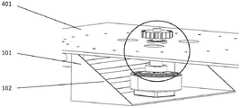
可选地,所述货叉自主旋转部分位于液压式剪叉抬升平台上,与货叉前移部分底板通过滑块和外部大齿轮连接,包括固定电机架、驱动电机、联接键、连接套、深沟球轴承、中间主动齿轮、被动惰轮、外部大齿轮、弧形导轨滑块及弧形导轨;所述固定电机架一端与液压式剪叉抬升平台相连,一端与驱动电机相连;所述连接套一端与驱动电机相连,一端通过联接键与中间主动齿轮相连;所述中间主动齿轮和被动惰轮均通过深沟球轴承固定在液压式剪叉抬升平台;所述外部大齿轮与货叉前移部分的底板固结;所述弧形导轨固定在液压式剪叉抬升平台,两个弧形导轨构成与中间主动齿轮圆心同心的圆,弧形导轨上均匀分布三个弧形导轨滑块,与货叉前移部分的底板相连。Optionally, the autonomous rotating part of the fork is located on the hydraulic scissor lift platform, and is connected with the bottom plate of the forward moving part of the fork through a slider and an external large gear, including a fixed motor frame, a drive motor, a coupling key, a connection sleeve, deep groove ball bearing, intermediate driving gear, passive idler, external large gear, arc guide slider and arc guide; one end of the fixed motor frame is connected with the hydraulic scissor lift platform, and the other end is connected with the drive motor; the One end of the connecting sleeve is connected with the driving motor, and the other end is connected with the intermediate driving gear through the connecting key; the intermediate driving gear and the passive idler are both fixed on the hydraulic scissor lifting platform through the deep groove ball bearing; the external large gear is connected to the fork The bottom plate of the forward moving part is consolidated; the arc guide rail is fixed on the hydraulic scissor lift platform, the two arc guide rails form a circle concentric with the center of the middle driving gear, and three arc guide rail sliders are evenly distributed on the arc guide rail , which is connected with the bottom plate of the forward part of the fork.
可选地,所述推拉式电磁铁夹抱部分位于液压式剪叉抬升平台上,包括推拉式电磁铁部分、连接板、短连接轴、弧形夹抱杆1、中连接轴、连杆、弧形夹抱杆2、长连接轴及导向轮。所述推拉式电磁铁部分包括电磁铁底座、电磁铁、导杆及弹簧,电磁铁底座与液压式剪叉抬升平台相连固定,上部通过连接板与弧形夹抱杆1一端相连,相连的弧形夹抱杆1中间通过中连接轴与液压式剪叉抬升平台相连;所述两弧形夹抱杆通过短连接轴与连杆相连;所述弧形夹抱杆2中间通过中连接轴与液压式剪叉抬升平台相连,一端通过长连接轴与导向轮相连,导向轮约束在液压式剪叉抬升平台所开的槽中。Optionally, the push-pull electromagnet clamping part is located on the hydraulic scissors lifting platform, and includes a push-pull electromagnet part, a connecting plate, a short connecting shaft, an arc-shaped clamping rod 1, a middle connecting shaft, a connecting rod, Arc clamp rod 2, long connecting shaft and guide wheel. The push-pull electromagnet part includes an electromagnet base, an electromagnet, a guide rod and a spring. The electromagnet base is connected and fixed with the hydraulic scissor lift platform, and the upper part is connected with one end of the arc-shaped clamping rod 1 through a connecting plate. The middle of the clamping rod 1 is connected with the hydraulic scissor lifting platform through the middle connecting shaft; the two arc clamping rods are connected with the connecting rod through the short connecting shaft; the middle of the arc clamping rod 2 is connected with the connecting shaft through the middle connecting shaft. The hydraulic scissor lift platform is connected, one end is connected with the guide wheel through a long connecting shaft, and the guide wheel is constrained in the groove opened by the hydraulic scissor lift platform.
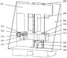
可选地,所述翻转压稳部分位于前移部分车体上,分为上升部分和翻转部分,U型板连接上升部分和翻转部分;所述上升部分包括电机、连电机板、联轴器、丝杠、轴承座、丝杠滑块、导轨、导轨滑块和U型板。所述电机通过连电机板与前移部分车体相连,电机输出轴通过联轴器与丝杠相连;所述丝杠由两个轴承座固定在前移部分车体;所述U型板与丝杠滑块和导轨滑块相连。所述翻转部分包括电机、联轴器、旋转轴、连接件、导向轴、导向板、翻转板和U型板。所述连接件一端与翻转板相连,一端通过旋转轴和导向轴与导向板相连;所述电机固定在U型板上,电机通过联轴器与旋转轴相连。Optionally, the overturning pressure stabilization part is located on the body of the forward moving part, and is divided into an ascending part and an overturning part, and the U-shaped plate connects the ascending part and the overturning part; the ascending part includes a motor, a motor-connecting plate, and a coupling. , screw, bearing seat, screw slider, guide rail, guide rail slider and U-shaped plate. The motor is connected to the forward-moving part of the vehicle body through a connecting motor plate, and the motor output shaft is connected to the lead screw through a coupling; the lead screw is fixed on the forward-moving part of the vehicle body by two bearing seats; the U-shaped plate is connected to the lead screw. The lead screw slider is connected with the guide rail slider. The turning part includes a motor, a coupling, a rotating shaft, a connecting piece, a guiding shaft, a guiding plate, a turning plate and a U-shaped plate. One end of the connecting piece is connected with the turning plate, and the other end is connected with the guide plate through the rotating shaft and the guiding shaft; the motor is fixed on the U-shaped plate, and the motor is connected with the rotating shaft through the coupling.
可选地,所述液压式剪叉抬升部分包括平台、支撑杆、长横杆、中横杆、短横杆、底座、液压缸及液压杆。所述平台前端通过中横杆与支撑杆相连,后端通过短横杆与支撑杆相连;所述支撑杆通过长横杆、中横杆及短横杆相互配合连接,形成剪叉结构;所述液压缸与底座相连,液压杆装在液压缸内,液压杆通过长横杆与底座相连;所述底座固定在整体车身上。Optionally, the hydraulic scissor lifting part includes a platform, a support rod, a long cross rod, a middle cross rod, a short cross rod, a base, a hydraulic cylinder and a hydraulic rod. The front end of the platform is connected with the support rod through the middle cross rod, and the rear end is connected with the support rod through the short cross rod; the support rod is connected with each other through the long cross rod, the middle cross rod and the short cross rod to form a scissor fork structure; The hydraulic cylinder is connected with the base, the hydraulic rod is installed in the hydraulic cylinder, and the hydraulic rod is connected with the base through a long cross rod; the base is fixed on the overall body.
可选地,所述货叉前移部分包括前移部分车体、导轨轮架、导轨轮、电机、联轴器、丝杠、丝杠滑块及轴承座。所述电机固定在液压式剪叉抬升平台,电机与联轴器相连,之后与丝杠相连;所述丝杠滑块与前移部分车身相连;所述导轨轮固定在前移部分车身,安装在导轨轮架上;所述导轨轮架固定在液压式剪叉抬升平台。Optionally, the forward-moving part of the fork includes a body of the forward-moving part, a guide wheel frame, a guide wheel, a motor, a coupling, a lead screw, a lead screw slider and a bearing seat. The motor is fixed on the hydraulic scissor lift platform, the motor is connected with the coupling, and then connected with the lead screw; the lead screw slider is connected with the forward-moving part of the body; the guide wheel is fixed on the forward-moving part of the body, installed On the guide rail wheel frame; the guide rail wheel frame is fixed on the hydraulic scissor lift platform.
本发明的有益效果在于:提供一种旋转夹抱式货叉运输叉车,通过货叉的自主旋转结构,能够满足多方位装卸货需求。夹抱式结构能够满足货叉制动及承担部分载荷功能。同时使得叉车能够在狭小空间完成装卸货功能,提高其灵活性。The beneficial effects of the present invention are: to provide a rotary gripping fork transport forklift, which can meet the multi-directional loading and unloading requirements through the autonomous rotation structure of the forks. The clip-on structure can satisfy the fork braking and bear part of the load function. At the same time, the forklift can complete the loading and unloading function in a small space and improve its flexibility.
附图说明Description of drawings
图1为本发明整体结构图;Fig. 1 is the overall structure diagram of the present invention;
图2为本发明轮系旋转及夹抱结构图;Fig. 2 is the structure diagram of wheel train rotation and clamping according to the present invention;
图3为本发明翻转压稳结构图;FIG. 3 is a structural diagram of a flip voltage stabilization of the present invention;
图4为本发明主动齿轮连接结构图;Fig. 4 is the connection structure diagram of the driving gear of the present invention;
图5为本发明主动齿轮连接细节图;FIG. 5 is a detailed view of the connection of the driving gear of the present invention;
图中:货叉(8)、前移部分底板(509)、导轨轮架(503)、短横杆(403)、长横杆(405)、液压杆(406)、底部车身(6)、叉车轮(7)、底座(408)、支撑杆(404)、平台(401)、前移车身(501)、翻转板(317)、长连接轴(211)、导向轮(212)、弧形导轨滑块(109)、被动惰轮(107)、中间主动齿轮(106)、外部大齿轮(108)、弧形导轨(110)、弧形夹抱杆2(210)、连杆(209)、短连接轴(206)、中连接轴(208)、弧形夹抱杆1(207)、电磁铁底座(201)、导杆(203)、电磁铁(202)、连接板(205)、弹簧(204)、电机(311)、联轴器(312)、连接件(314)、导向轴(315)、导向板(316)、连电机板(302)、联轴器(303)、轴承座(305)、旋转轴(313)、U型板(309)、六角头螺栓M8(318)、导轨(307)、丝杠(304)、固定电机架(101)、驱动电机(102)、连接套(104)、联接键(103)、深沟球轴承(105)。In the figure: fork (8), forward part bottom plate (509), rail wheel frame (503), short crossbar (403), long crossbar (405), hydraulic rod (406), bottom body (6), Fork wheel (7), base (408), support rod (404), platform (401), forward body (501), turning plate (317), long connecting shaft (211), guide wheel (212), arc Guide rail slider (109), passive idler gear (107), intermediate driving gear (106), external large gear (108), arc guide rail (110), arc clamp rod 2 (210), connecting rod (209) , short connecting shaft (206), middle connecting shaft (208), arc clamp rod 1 (207), electromagnet base (201), guide rod (203), electromagnet (202), connecting plate (205), Spring (204), motor (311), coupling (312), connecting piece (314), guide shaft (315), guide plate (316), motor-connecting plate (302), coupling (303), bearing seat (305), rotating shaft (313), U-shaped plate (309), hexagon head bolt M8 (318), guide rail (307), lead screw (304), fixed motor frame (101), drive motor (102), A connecting sleeve (104), a coupling key (103), and a deep groove ball bearing (105).
具体实施方式Detailed ways
为了更好解释本发明,便于理解,下面结合附图对本发明进行详细描述。In order to better explain the present invention and facilitate understanding, the present invention will be described in detail below with reference to the accompanying drawings.
结合图1,本发明是一种旋转夹抱式货叉运输叉车,主要包括货叉自主旋转部分、推拉式电磁铁夹抱部分、翻转压稳部分、液压式剪叉抬升部分、货叉前移部分和车身四轮驱动部分。Referring to Figure 1, the present invention is a rotary gripping fork transport forklift, which mainly includes an autonomous rotating part of the fork, a push-pull electromagnet gripping part, a flipping pressure stabilization part, a hydraulic scissor fork lifting part, and a fork forward moving part. part and body 4WD part.
结合图2和图4,货叉自主旋转部分结构位于液压式剪叉抬升平台上,与货叉前移部分底板通过滑块和外部大齿轮连接,包括固定电机架、驱动电机、联接键、连接套、深沟球轴承、中间主动齿轮、被动惰轮、外部大齿轮、弧形导轨滑块及弧形导轨。固定电机架一端与液压式剪叉抬升平台相连,一端与驱动电机相连,达到固定电机的作用。连接套一端与驱动电机相连,一端通过联接键与中间主动齿轮相连,使得电机能够与齿轮相连,驱动中间主动齿轮转动。中间主动齿轮和被动惰轮均通过深沟球轴承固定在液压式剪叉抬升平台,外部大齿轮与货叉前移部分的底板固结,中间主动齿轮转动带动被动惰轮转动,带动外部大齿轮转动,最后带动货叉前移部分的底板转动,实现整体货叉的转动。弧形导轨固定在液压式剪叉抬升平台,两个弧形导轨构成与中间主动齿轮圆心同心的圆,弧形导轨上均匀分布三个弧形导轨滑块,与货叉前移部分的底板相连,底板转动后带动三个弧形导轨滑块绕弧形导轨转动,不影响整体的旋转,并且能够分担载荷。Combined with Figure 2 and Figure 4, the structure of the autonomous rotating part of the fork is located on the hydraulic scissor lifting platform, and is connected to the bottom plate of the forward part of the fork through the slider and the external large gear, including the fixed motor frame, the drive motor, the coupling key, the connection Sleeve, deep groove ball bearing, intermediate driving gear, passive idler, external large gear, arc guide slider and arc guide. One end of the fixed motor frame is connected with the hydraulic scissor lifting platform, and the other end is connected with the driving motor, so as to achieve the function of fixing the motor. One end of the connecting sleeve is connected with the driving motor, and the other end is connected with the intermediate driving gear through the connecting key, so that the motor can be connected with the gear and drive the intermediate driving gear to rotate. Both the intermediate driving gear and the passive idler gear are fixed on the hydraulic scissor lifting platform through deep groove ball bearings. The external large gear is consolidated with the bottom plate of the forward part of the fork. The rotation of the intermediate driving gear drives the passive idler to rotate, which drives the external large gear. Rotate, and finally drive the bottom plate of the forward part of the fork to rotate, so as to realize the rotation of the whole fork. The arc-shaped guide rail is fixed on the hydraulic scissor lift platform. The two arc-shaped guide rails form a circle concentric with the center of the middle driving gear. The arc-shaped guide rails are evenly distributed with three arc-shaped guide rail sliders, which are connected to the bottom plate of the forward part of the fork. , After the bottom plate rotates, it drives the three arc-shaped guide rail sliders to rotate around the arc-shaped guide rail, which does not affect the overall rotation and can share the load.
结合图2,推拉式电磁铁夹抱部分位于液压式剪叉抬升平台上,包括推拉式电磁铁部分、连接板、短连接轴、弧形夹抱杆1、中连接轴、连杆、弧形夹抱杆2、长连接轴及导向轮。推拉式电磁铁部分包括电磁铁底座、电磁铁、导杆及弹簧,电磁铁底座与液压式剪叉抬升平台相连固定,上端通过连接板与弧形夹抱杆1一端相连,相连的弧形夹抱杆1中部通过中连接轴与液压式剪叉抬升平台相连,两弧形夹抱杆通过短连接轴与连杆相连,弧形夹抱杆2中部通过中连接轴与液压式剪叉抬升平台相连,一端通过长连接轴与导向轮相连,导向轮约束在液压式剪叉抬升平台所开的槽中。推拉式电磁铁处于断电情况时,两弧形夹抱杆弹开,通电时,电磁铁瞬间向前推进,压缩弹簧,与电磁铁连接的弧形夹抱杆1以中连接轴为圆心转动,夹住前移部分底板,同时弧形夹抱杆2由连杆带动,以中连接轴为圆心转动,对前移部分底板起夹抱作用,导向轮起支撑和导向作用。With reference to Figure 2, the push-pull electromagnet clamping part is located on the hydraulic scissor lift platform, including the push-pull electromagnet part, the connecting plate, the short connecting shaft, the arc clamping rod 1, the middle connecting shaft, the connecting rod, the arc Clamping rod 2, long connecting shaft and guide wheel. The push-pull electromagnet part includes an electromagnet base, an electromagnet, a guide rod and a spring. The electromagnet base is connected and fixed with the hydraulic scissor lift platform, and the upper end is connected to one end of the arc clamp rod 1 through a connecting plate. The middle part of the pole 1 is connected to the hydraulic scissor lift platform through the middle connecting shaft, the two arc clamp poles are connected to the connecting rod through the short connecting shaft, and the middle part of the arc clip pole 2 is connected to the hydraulic scissor lift platform through the middle connecting shaft. One end is connected with the guide wheel through a long connecting shaft, and the guide wheel is constrained in the groove opened by the hydraulic scissor lift platform. When the push-pull electromagnet is in a power-off condition, the two arc-shaped clamp rods pop open. When the power is turned on, the electromagnet pushes forward instantaneously, compressing the spring, and the arc-shaped clamp rod 1 connected with the electromagnet rotates with the middle connecting shaft as the center of the circle. , clamp the forward-moving part of the bottom plate, and at the same time, the arc-shaped clamping rod 2 is driven by the connecting rod and rotates with the middle connecting shaft as the center of the circle, which clamps the forward-moving part of the bottom plate, and the guide wheel plays a supporting and guiding role.
结合图3,翻转压稳部分位于前移部分车体上,分为上升部分和翻转部分,U型板连接上升部分和翻转部分。上升部分包括电机、连电机板、联轴器、丝杠、轴承座、丝杠滑块、导轨、导轨滑块和U型板。电机通过连电机板与前移部分车体相连,电机输出轴通过联轴器与丝杠相连,丝杠由两个轴承座固定在前移部分车体,U型板与丝杠滑块和导轨滑块相连。电机驱动,通过联轴器带动丝杠转动,丝杠滑块由丝杠带动向上移动,U型板与丝杠滑块和导轨滑块连接,丝杠滑块带动U型板向上移动,带动导轨滑块沿导轨向上移动,导轨起导向作用。翻转部分包括电机、联轴器、旋转轴、连接件、导向轴、导向板、翻转板和U型板。连接件一端与翻转板相连,一端通过旋转轴和导向轴与导向板相连,电机固定在U型板上,电机驱动,通过联轴器与旋转轴相连,带动连接件旋转,连接件带动翻转板沿导向板指定路径翻转90°,达到压稳货物的功能。上升部分和翻转部分可联动使用,在翻转板高于运输货物的高度时,上升部分能够适当下降,翻转板高度下降,压住货物。Referring to Figure 3, the overturning pressure stabilization part is located on the body of the forward moving part, and is divided into an ascending part and an overturning part, and the U-shaped plate connects the ascending part and the overturning part. The rising part includes the motor, the motor-connecting plate, the coupling, the lead screw, the bearing seat, the lead screw slider, the guide rail, the guide rail slider and the U-shaped plate. The motor is connected with the body of the forward moving part through the connecting motor plate, and the output shaft of the motor is connected with the lead screw through the coupling. Slider connected. Driven by the motor, the lead screw is driven to rotate through the coupling, and the lead screw slider is driven by the lead screw to move upward. The slider moves up along the guide rail, and the guide rail plays a guiding role. The flip part includes a motor, a coupling, a rotating shaft, a connecting piece, a guide shaft, a guide plate, a flip plate and a U-shaped plate. One end of the connecting piece is connected with the turning plate, and the other end is connected with the guiding plate through the rotating shaft and the guiding shaft. The motor is fixed on the U-shaped plate. Flip 90° along the designated path of the guide plate to achieve the function of compressing and stabilizing the goods. The rising part and the overturning part can be used in linkage. When the overturning plate is higher than the height of the transported goods, the rising part can be lowered properly, and the height of the overturning plate is lowered to press the goods.
液压式剪叉抬升部分包括平台、支撑杆、长横杆、中横杆、短横杆、底座、液压缸及液压杆。平台前端通过中横杆与支撑杆相连,后端通过短横杆与支撑杆相连,支撑杆通过长横杆、中横杆及短横杆相互配合连接,形成剪叉结构,液压缸与底座相连,液压杆装在液压缸内,液压杆通过长横杆与底座相连底座固定在整体车身上。液压杆受油压驱动沿液压缸后移,带动与底座相连的长横杆沿底座槽移动,长横杆与支撑杆连接,带动整体剪叉结构展开,达到整体抬升功能。同样的,液压杆受油压沿液压缸前移时,整体剪叉结构收回,达到整体下降功能。The lifting part of the hydraulic scissors includes a platform, a support rod, a long cross rod, a middle cross rod, a short cross rod, a base, a hydraulic cylinder and a hydraulic rod. The front end of the platform is connected with the support rod through the middle cross rod, the rear end is connected with the support rod through the short cross rod, the support rod is connected with each other through the long cross rod, the middle cross rod and the short cross rod to form a scissor structure, and the hydraulic cylinder is connected with the base , The hydraulic rod is installed in the hydraulic cylinder, and the hydraulic rod is connected with the base through the long cross rod and the base is fixed on the whole body. The hydraulic rod is driven by the oil pressure to move backward along the hydraulic cylinder, which drives the long cross rod connected to the base to move along the base groove. Similarly, when the hydraulic rod moves forward along the hydraulic cylinder under oil pressure, the overall scissor structure retracts to achieve the overall lowering function.
货叉前移部分包括前移部分车体、导轨轮架、导轨轮、电机、联轴器、丝杠、丝杠滑块和轴承座。电机固定在液压式剪叉抬升平台,电机与联轴器相连,之后与丝杠相连,电机通过联轴器带动丝杠转动,使丝杠滑块实现前移和后退功能,丝杠滑块与前移部分车身相连,带动前移部分车身前移,导轨轮固定在前移部分车身,安装在导轨轮架上,所述导轨轮架固定在液压式剪叉抬升平台,起到导向和分担载荷作用。The forward moving part of the fork includes the forward moving part of the body, the guide wheel frame, the guide wheel, the motor, the coupling, the lead screw, the lead screw slider and the bearing seat. The motor is fixed on the hydraulic scissor lift platform. The motor is connected with the coupling, and then connected with the lead screw. The motor drives the lead screw to rotate through the coupling, so that the lead screw slider can achieve forward and backward functions. The forward-moving part of the body is connected to drive the forward-moving part of the body to move forward. The guide wheel is fixed on the forward-moving part of the body and is installed on the guide wheel frame. The guide wheel frame is fixed on the hydraulic scissor lift platform to guide and share the load. effect.
叉车处于初始状态时,剪叉结构收缩,推拉式电磁铁通电,两弧形夹抱杆将前移部分底板夹抱住。叉车运动到指定装载货物的地点后,液压杆受油压驱动,带动长横杆移动,剪叉结构展开,剪叉平台上升。上升到指定高度之后,货叉前移,装载货物,货叉收回,剪叉结构收回,翻转压稳部分在电机驱动下沿丝杆和导轨上升,到达指定位置后翻转部分电机驱动,翻转板沿导向板指定路径翻转,压稳货物,若翻转板高度过高,上升部分电机反向驱动,使翻转板整体下降,压稳货物,完成叉货过程。货叉有旋转要求时,推拉式电磁铁断电,弹簧弹开,两弧形夹抱杆张开,与中间主动齿轮相连的电机驱动齿轮,带动轮系转动,上部货叉整体转动,带动三滑块沿弧形导轨转动,同时分担载荷,旋转到指定位置后,推拉式电磁铁通电,弹簧收缩,两弧形夹抱杆收缩夹抱,保证稳定。当叉车需要卸货时,按照叉车上述叉货过程反向进行即可卸货。此为本发明完整的实施步骤。When the forklift is in the initial state, the scissor structure shrinks, the push-pull electromagnet is energized, and the two arc-shaped clamp bars hold the forward-moving part of the bottom plate clamp. After the forklift moves to the designated location for loading the goods, the hydraulic rod is driven by the oil pressure to drive the long horizontal rod to move, the scissor structure unfolds, and the scissor platform rises. After rising to the specified height, the fork moves forward, loads the goods, retracts the fork, and retracts the scissor structure. The designated path of the guide plate is turned over to stabilize the goods. If the height of the overturning plate is too high, the motor of the ascending part will be driven in the reverse direction, so that the entirety of the overturning plate will be lowered, the goods will be stabilized, and the forklift process will be completed. When the fork is required to rotate, the push-pull electromagnet is powered off, the spring springs open, the two arc-shaped clamping rods are opened, and the motor connected with the middle driving gear drives the gear to drive the wheel train to rotate, and the upper fork rotates as a whole, driving the three. The slider rotates along the arc guide rail, and shares the load at the same time. After rotating to the designated position, the push-pull electromagnet is energized, the spring contracts, and the two arc clamp rods contract and clamp to ensure stability. When the forklift needs to unload the goods, the forklift can be unloaded in the reverse direction according to the above forklift process. This is the complete implementation step of the present invention.
上面结合附图对本发明进行描述,但是本发明并不局限于上述的具体实施方式,上述的具体实施方式仅仅是示意性的,而不是限制性的,本领域的普通技术人员在本发明的启示下,在不脱离本发明宗旨和权利要求所保护的范围情况下,还可做出很多形式,这些均属于本发明的保护之中。The present invention is described above in conjunction with the accompanying drawings, but the present invention is not limited to the above-mentioned specific embodiments. The above-mentioned specific embodiments are only schematic rather than restrictive. Below, without departing from the spirit of the present invention and the scope of protection of the claims, many forms can be made, which all belong to the protection of the present invention.
Claims (6)
Priority Applications (1)
| Application Number | Priority Date | Filing Date | Title |
|---|---|---|---|
| CN202210306566.1ACN114604799A (en) | 2022-03-25 | 2022-03-25 | Fork truck structure of formula fork is embraced to rotatory clamp |
Applications Claiming Priority (1)
| Application Number | Priority Date | Filing Date | Title |
|---|---|---|---|
| CN202210306566.1ACN114604799A (en) | 2022-03-25 | 2022-03-25 | Fork truck structure of formula fork is embraced to rotatory clamp |
Publications (1)
| Publication Number | Publication Date |
|---|---|
| CN114604799Atrue CN114604799A (en) | 2022-06-10 |
Family
ID=81867441
Family Applications (1)
| Application Number | Title | Priority Date | Filing Date |
|---|---|---|---|
| CN202210306566.1APendingCN114604799A (en) | 2022-03-25 | 2022-03-25 | Fork truck structure of formula fork is embraced to rotatory clamp |
Country Status (1)
| Country | Link |
|---|---|
| CN (1) | CN114604799A (en) |
Cited By (1)
| Publication number | Priority date | Publication date | Assignee | Title |
|---|---|---|---|---|
| CN115123962A (en)* | 2022-07-08 | 2022-09-30 | 中国建筑一局(集团)有限公司 | Inclined pipeline carrying lifting vehicle and using method thereof |
Citations (9)
| Publication number | Priority date | Publication date | Assignee | Title |
|---|---|---|---|---|
| JP2011026030A (en)* | 2009-07-22 | 2011-02-10 | Nippon Yusoki Co Ltd | Fork moving device of cargo handling vehicle |
| CN203754357U (en)* | 2013-12-13 | 2014-08-06 | 泰州海陵液压机械有限公司 | High-precision self-scissor-type hydraulic lifting platform traveling mechanism |
| CN204508675U (en)* | 2015-01-16 | 2015-07-29 | 升华电梯有限公司 | The thick-and-thin cam-type electromagnetic brake in band-type brake gap can be controlled |
| CN109850802A (en)* | 2019-03-29 | 2019-06-07 | 中科微至智能制造科技江苏有限公司 | Pallet lifting device |
| CN211282609U (en)* | 2019-12-04 | 2020-08-18 | 无锡市丰玮机械设备有限公司 | Large-scale barrel transfer device for cross guide rail |
| CN211594934U (en)* | 2020-01-18 | 2020-09-29 | 友力特(厦门)叉车属具有限公司 | Rotator device with hook plate |
| CN112707339A (en)* | 2021-01-06 | 2021-04-27 | 凯迈(洛阳)测控有限公司 | Lift trailer |
| CN214087548U (en)* | 2020-12-10 | 2021-08-31 | 蚌埠鑫运力搬运设备有限公司 | Turnover forklift convenient to carry |
| CN217676648U (en)* | 2022-03-25 | 2022-10-28 | 中科微至智能制造科技江苏股份有限公司 | Fork truck structure of rotary clamping type fork |
- 2022
- 2022-03-25CNCN202210306566.1Apatent/CN114604799A/enactivePending
Patent Citations (9)
| Publication number | Priority date | Publication date | Assignee | Title |
|---|---|---|---|---|
| JP2011026030A (en)* | 2009-07-22 | 2011-02-10 | Nippon Yusoki Co Ltd | Fork moving device of cargo handling vehicle |
| CN203754357U (en)* | 2013-12-13 | 2014-08-06 | 泰州海陵液压机械有限公司 | High-precision self-scissor-type hydraulic lifting platform traveling mechanism |
| CN204508675U (en)* | 2015-01-16 | 2015-07-29 | 升华电梯有限公司 | The thick-and-thin cam-type electromagnetic brake in band-type brake gap can be controlled |
| CN109850802A (en)* | 2019-03-29 | 2019-06-07 | 中科微至智能制造科技江苏有限公司 | Pallet lifting device |
| CN211282609U (en)* | 2019-12-04 | 2020-08-18 | 无锡市丰玮机械设备有限公司 | Large-scale barrel transfer device for cross guide rail |
| CN211594934U (en)* | 2020-01-18 | 2020-09-29 | 友力特(厦门)叉车属具有限公司 | Rotator device with hook plate |
| CN214087548U (en)* | 2020-12-10 | 2021-08-31 | 蚌埠鑫运力搬运设备有限公司 | Turnover forklift convenient to carry |
| CN112707339A (en)* | 2021-01-06 | 2021-04-27 | 凯迈(洛阳)测控有限公司 | Lift trailer |
| CN217676648U (en)* | 2022-03-25 | 2022-10-28 | 中科微至智能制造科技江苏股份有限公司 | Fork truck structure of rotary clamping type fork |
Cited By (2)
| Publication number | Priority date | Publication date | Assignee | Title |
|---|---|---|---|---|
| CN115123962A (en)* | 2022-07-08 | 2022-09-30 | 中国建筑一局(集团)有限公司 | Inclined pipeline carrying lifting vehicle and using method thereof |
| CN115123962B (en)* | 2022-07-08 | 2025-01-14 | 中国建筑一局(集团)有限公司 | Inclined pipeline carrying lifting vehicle and application method thereof |
Similar Documents
| Publication | Publication Date | Title |
|---|---|---|
| CN205706765U (en) | A kind of express delivery power trolley of quick unloading | |
| CN114604799A (en) | Fork truck structure of formula fork is embraced to rotatory clamp | |
| CN102815643B (en) | Vehicle mounted type handling goods implement | |
| CN211545825U (en) | Forklift device for lifting and pushing goods | |
| CN217676648U (en) | Fork truck structure of rotary clamping type fork | |
| CN208603662U (en) | A kind of carrier with double-layer lifting pallet fork | |
| CN118183565A (en) | A pallet truck for transporting field-shaped pallets | |
| CN105644570A (en) | Novel railway truck for piggyback type transportation | |
| JP3011356B2 (en) | Shuttle lifter | |
| CN2910886Y (en) | Hand cart for transporting goods | |
| CN216377343U (en) | Forklift truck | |
| CN202130370U (en) | Container carrier | |
| CN206915695U (en) | A kind of special crotch assembly | |
| CN215101806U (en) | Fork truck portal convenient to fork goods | |
| CN210912516U (en) | A power-assisted truck | |
| CN212198379U (en) | Novel electric energy-saving carrier | |
| CN211871305U (en) | Self-locking type high-stability fork type AGV convenient to align | |
| CN212292690U (en) | Forklift loading and unloading mechanism for wooden box | |
| CN209635801U (en) | A kind of shipping yard lifting transfer car(buggy) | |
| CN222433226U (en) | Tray transfer robot applicable to both Chinese character ' Tian ' shaped support and Chuan ' shaped support | |
| CN218201121U (en) | Tray lifting shifter | |
| CN217674771U (en) | Automatic plate material proportioning device | |
| CN217076302U (en) | Over-and-under type discharge devices based on freight train is unloaded | |
| CN215398614U (en) | Self-loading and unloading hydraulic flat-plate transport vehicle | |
| CN221477172U (en) | Multifunctional cart for material transfer |
Legal Events
| Date | Code | Title | Description |
|---|---|---|---|
| PB01 | Publication | ||
| PB01 | Publication | ||
| SE01 | Entry into force of request for substantive examination | ||
| SE01 | Entry into force of request for substantive examination |