CN114601515A - Suture anchor, system and implantation method thereof - Google Patents
Suture anchor, system and implantation method thereofDownload PDFInfo
- Publication number
- CN114601515A CN114601515ACN202011404235.9ACN202011404235ACN114601515ACN 114601515 ACN114601515 ACN 114601515ACN 202011404235 ACN202011404235 ACN 202011404235ACN 114601515 ACN114601515 ACN 114601515A
- Authority
- CN
- China
- Prior art keywords
- suture anchor
- anchor
- blade
- rotary blade
- suture
- Prior art date
- Legal status (The legal status is an assumption and is not a legal conclusion. Google has not performed a legal analysis and makes no representation as to the accuracy of the status listed.)
- Pending
Links
Images


Classifications
- A—HUMAN NECESSITIES
- A61—MEDICAL OR VETERINARY SCIENCE; HYGIENE
- A61B—DIAGNOSIS; SURGERY; IDENTIFICATION
- A61B17/00—Surgical instruments, devices or methods
- A61B17/04—Surgical instruments, devices or methods for suturing wounds; Holders or packages for needles or suture materials
- A61B17/0401—Suture anchors, buttons or pledgets, i.e. means for attaching sutures to bone, cartilage or soft tissue; Instruments for applying or removing suture anchors
- A61B2017/0408—Rivets
- A—HUMAN NECESSITIES
- A61—MEDICAL OR VETERINARY SCIENCE; HYGIENE
- A61B—DIAGNOSIS; SURGERY; IDENTIFICATION
- A61B17/00—Surgical instruments, devices or methods
- A61B17/04—Surgical instruments, devices or methods for suturing wounds; Holders or packages for needles or suture materials
- A61B17/0401—Suture anchors, buttons or pledgets, i.e. means for attaching sutures to bone, cartilage or soft tissue; Instruments for applying or removing suture anchors
- A61B2017/0445—Suture anchors, buttons or pledgets, i.e. means for attaching sutures to bone, cartilage or soft tissue; Instruments for applying or removing suture anchors cannulated, e.g. with a longitudinal through-hole for passage of an instrument
- A—HUMAN NECESSITIES
- A61—MEDICAL OR VETERINARY SCIENCE; HYGIENE
- A61B—DIAGNOSIS; SURGERY; IDENTIFICATION
- A61B17/00—Surgical instruments, devices or methods
- A61B17/04—Surgical instruments, devices or methods for suturing wounds; Holders or packages for needles or suture materials
- A61B17/0401—Suture anchors, buttons or pledgets, i.e. means for attaching sutures to bone, cartilage or soft tissue; Instruments for applying or removing suture anchors
- A61B2017/0446—Means for attaching and blocking the suture in the suture anchor
- A—HUMAN NECESSITIES
- A61—MEDICAL OR VETERINARY SCIENCE; HYGIENE
- A61B—DIAGNOSIS; SURGERY; IDENTIFICATION
- A61B17/00—Surgical instruments, devices or methods
- A61B17/04—Surgical instruments, devices or methods for suturing wounds; Holders or packages for needles or suture materials
- A61B17/0401—Suture anchors, buttons or pledgets, i.e. means for attaching sutures to bone, cartilage or soft tissue; Instruments for applying or removing suture anchors
- A61B2017/0464—Suture anchors, buttons or pledgets, i.e. means for attaching sutures to bone, cartilage or soft tissue; Instruments for applying or removing suture anchors for soft tissue
Landscapes
- Health & Medical Sciences (AREA)
- Surgery (AREA)
- Life Sciences & Earth Sciences (AREA)
- Biomedical Technology (AREA)
- Nuclear Medicine, Radiotherapy & Molecular Imaging (AREA)
- Engineering & Computer Science (AREA)
- Rheumatology (AREA)
- Heart & Thoracic Surgery (AREA)
- Medical Informatics (AREA)
- Molecular Biology (AREA)
- Animal Behavior & Ethology (AREA)
- General Health & Medical Sciences (AREA)
- Public Health (AREA)
- Veterinary Medicine (AREA)
- Surgical Instruments (AREA)
Abstract
Translated fromChinese
Description
Translated fromChinese技术领域technical field
本发明涉及一种医疗的器械,尤其涉及一种用于植入骨骼手术的缝合锚钉与其系统及植入方法。The present invention relates to a medical instrument, in particular to a suture anchor used for implantation in bone surgery, its system and its implantation method.
背景技术Background technique
锚钉是应用于缝合韧带等软组织的手术器械,使用于缝合手术时是先利用锚钉将缝线的一端固定于骨骼上,以缝线缝合软组织后,接着再使用另一锚钉将缝线另一端拉紧、固定。为了将锚钉植入骨骼中,目前的作法是以器械在骨骼凿出导孔,接着再以驱动杆穿入锚钉,转动驱动杆来带动锚钉由导孔锁入骨骼内。然而,上述的现有的做法存在一些问题。Anchor is a surgical instrument used to suture soft tissues such as ligaments. When used in suture surgery, one end of the suture is first fixed on the bone with the anchor, and the soft tissue is sutured with the suture, and then another anchor is used to sew the suture. Tighten and fasten the other end. In order to implant the anchor into the bone, the current practice is to drill a guide hole in the bone with a device, and then a driving rod is inserted into the anchor, and the driving rod is rotated to drive the anchor to be locked into the bone through the guide hole. However, there are some problems with the above-mentioned existing practice.
首先,现有的锚钉一般周围的螺牙是三角形的螺牙,因此锚钉利用螺牙锁入骨骼内时,接触骨骼的面积较小因此螺锁后的结构较不稳固,无法更紧密地结合骨骼内。再者,由于锚钉是以螺锁于导孔的方式固定,故于螺锁锚钉前需要预先在骨骼凿出较大的导孔,此对骨骼周边组织的破坏程度较大,不利于手术后愈合,且锚钉的牢固性亦较差,替换凿孔与驱动杆等器械的步骤亦使得手术变得更加繁琐又耗时。First of all, the existing anchors generally have triangular-shaped screws around them. Therefore, when the anchor is locked into the bone by using the screw teeth, the contact area with the bone is small. Therefore, the structure after screw locking is less stable and cannot be locked more tightly. integrated within the bones. In addition, since the anchor is fixed by screwing in the guide hole, a larger guide hole needs to be drilled in the bone before screwing the anchor, which will damage the surrounding tissue of the bone to a greater degree, which is not conducive to the operation. After healing, and the anchorage is also less secure, the steps of replacing instruments such as chisels and drive rods also make the operation more tedious and time-consuming.
发明内容SUMMARY OF THE INVENTION
由于现有的锚钉固定于骨骼会有结构较不稳固,以及预先在骨骼凿出的导孔较大容易破坏骨骼周边组织造成愈合状况不佳的缺点。为此,本发明通过锚钉周围螺牙形成较大接触面积的设计,以及螺牙于前端形成入牙口的设计,达到锚钉螺锁于骨骼稳固以及锁入时破坏骨骼周边组织较少的功效。Because the existing anchors are fixed to the bone, they have the disadvantages that the structure is relatively unstable, and the guide holes drilled in advance in the bone are relatively large, and the surrounding tissue of the bone is easily damaged, resulting in poor healing. For this reason, the present invention achieves the effect that the anchor screw is firmly locked to the bone and less damage to the surrounding tissue of the bone is achieved through the design of forming a larger contact area around the anchor and the design of forming the entrance of the screw at the front end.
为达到前述目的,本发明提供一种缝合锚钉,设有一锚钉本体,是直管状并具有前、后两端,于该锚钉本体的轴心沿轴向贯穿一非圆形的旋刃插孔,于该锚钉本体的后端部形成一穿线构造,于该锚钉本体的外周面形成一沿螺锁方向由后向前螺旋延伸的螺牙构造,该螺牙构造前端螺旋的幅度收窄并于该锚钉本体的前端面形成一入牙口,该螺牙构造的截断面为梯形并且两侧之间的夹角为45至55度,该螺牙构造的截断面顶端定义为一牙山,该牙山的宽度为0.4至0.7mm。In order to achieve the aforementioned purpose, the present invention provides a suture anchor, which is provided with an anchor body, which is in the shape of a straight tube and has front and rear ends, and a non-circular rotating blade runs through the axis of the anchor body in the axial direction. The socket is formed with a threading structure at the rear end of the anchor body, and a screw thread structure extending from the rear to the front along the screw locking direction is formed on the outer peripheral surface of the anchor body. The front end face of the anchor body is narrowed and a tooth inlet is formed. The cross-sectional surface of the screw structure is trapezoidal and the angle between the two sides is 45 to 55 degrees. The top of the cross-sectional surface of the screw structure is defined as a Asan, the width of the Asan is 0.4 to 0.7 mm.
较佳的,该螺牙构造的高为0.6至0.9mm,该螺牙构造的截断面底端定义为一牙底,该牙底的宽度为1.1至1.3mm,该牙山与该牙底宽度尺寸的比值为0.5。或者,较佳的,该螺牙构造截断面两侧之间的夹角为50度,该螺牙构造的高为0.7mm,该牙山的宽度为0.6mm,该牙底的宽度为1.2mm。Preferably, the height of the thread structure is 0.6 to 0.9 mm, the bottom end of the truncated surface of the thread structure is defined as a tooth bottom, the width of the tooth bottom is 1.1 to 1.3 mm, the width of the tooth base and the tooth bottom are The ratio of dimensions is 0.5. Or, preferably, the angle between the two sides of the truncated surface of the thread structure is 50 degrees, the height of the thread structure is 0.7mm, the width of the asan is 0.6mm, and the width of the bottom of the thread is 1.2mm .
进一步的,该旋刃插孔是以该锚钉本体的轴心为中心的多边形孔,该旋刃插孔于该锚钉本体前端面的周围形成三个以上位于同一圆形轨迹的刃角,该入牙口位于沿该螺锁方向落后其中一刃角10至15度的位置,如此使该入牙口于旋转时紧跟于该刃角的后方。Further, the rotating edge insertion hole is a polygonal hole centered on the axis of the anchor body, and the rotating edge insertion hole forms three or more edge corners located on the same circular track around the front end face of the anchor body, The thread entry is located at a
为达到前述目的,本发明亦提供一种缝合锚钉系统,可供固定于一骨骼上,该缝合锚钉系统包括一前述的缝合锚钉以及一旋刃,其中:该旋刃是截断面形状配合该旋刃插孔的杆体,于该旋刃的前端形成一尖端部,该旋刃穿置于该缝合锚钉的该旋刃插孔使该尖端部向前穿出该旋刃插孔,当该旋刃旋转时可驱动该缝合锚钉,使该缝合锚体通过该螺牙构造螺锁入该骨骼。In order to achieve the aforementioned purpose, the present invention also provides a suture anchor system that can be fixed on a bone, the suture anchor system comprising the aforementioned suture anchor and a spiral edge, wherein: the spiral edge is in the shape of a truncated surface The rod body that cooperates with the rotating blade insertion hole forms a tip portion at the front end of the rotating blade, and the rotating blade is inserted into the rotating blade insertion hole of the suture anchor so that the tip portion passes forward through the rotating blade insertion hole, When the helical blade rotates, the suture anchor can be driven, so that the suture anchor body is screwed into the bone through the screw thread structure.
较佳的,该旋刃的长度为该缝合锚钉的两倍,该旋刃的后半部穿设于该缝合锚钉的该旋刃插孔并且前半部向前穿出该旋刃插孔。Preferably, the length of the helical blade is twice that of the suture anchor, the rear half of the helical blade passes through the helical blade insertion hole of the suture anchor, and the front half of the helical blade passes forward through the helical blade insertion hole. .
进一步的,该旋刃插孔是以该锚钉本体的轴心为中心的多边形孔,该旋刃插孔于该锚钉本体前端面的周围形成三个以上位于同一圆形轨迹的刃角,该入牙口位于沿该螺锁方向落后其中一刃角10至15度的位置,如此使该入牙口于旋转时紧跟于该刃角的后方。Further, the rotating edge insertion hole is a polygonal hole centered on the axis of the anchor body, and the rotating edge insertion hole forms three or more edge corners located on the same circular track around the front end face of the anchor body, The thread entry is located at a
当本发明前述的缝合锚钉或缝合锚钉系统使用时,是将配合旋刃插孔的旋刃穿过该缝合锚钉的旋刃插孔,由于缝合锚钉的旋刃插孔是非圆形,使得配合缝合锚钉的旋刃的截断面也是非圆形,在旋刃的周围形成数个外凸的刀刃。When the aforesaid suture anchor or suture anchor system of the present invention is used, the helical blade that matches the helical blade insertion hole is passed through the helical blade insertion hole of the suture anchor, because the helical blade insertion hole of the suture anchor is non-circular , so that the sectional surface of the rotating edge of the matching suture anchor is also non-circular, and several convex blades are formed around the rotating edge.
如此,当旋刃旋转时不仅可用于带动缝合锚钉旋转,且旋刃外凸的刀刃在旋转后能够扩大铣削的半径,在骨骼上形成足以供螺牙构造螺锁锁入的导孔,让螺牙构造能从前端的入牙口陆续锁入该旋刃前导形成的导孔,并使锚钉本体的整体体积能够通过旋刃插孔的缩小而设计为较小的体积,除了让施术医师能在一次的操作中将缝合锚钉旋入骨骼,省却更换器械凿孔与钻入锚钉的麻烦以外,也能够减少在骨骼设置缝合锚钉所需要破坏的骨骼周边组织,有益于后续组织伤口的愈合。In this way, when the helical blade rotates, it can not only be used to drive the suture anchor to rotate, but also the convex blade of the helical blade can expand the milling radius after rotation, forming a guide hole on the bone enough for the screw-tooth structure to lock in, allowing the screw to be locked. The screw-tooth structure can be successively locked into the guide hole formed by the leading edge of the rotating edge from the entrance of the front end, and the overall volume of the anchor body can be designed to a smaller volume through the reduction of the rotating edge socket. The suture anchor can be screwed into the bone in one operation, which saves the trouble of replacing the instrument and drilling the anchor, and can also reduce the damage to the surrounding tissue of the bone required to set the suture anchor in the bone, which is beneficial to the subsequent tissue wounds of healing.
此外,由于本发明于锚钉本体周围形成的螺牙构造相较于三角形螺牙,是两侧夹角以及牙山宽度较宽的设计,如此使螺牙构造更趋近于方形齿的结构,如此在缝合锚钉螺锁攻入骨骼时,能以较大面积的螺牙接触、咬合于骨骼,能够获得螺锁结合更为稳固的构造,再以后端部的穿线构造用于系绑或穿线绞合于螺牙构造与骨骼之间的方式固定手术的缝合线。In addition, since the screw structure formed around the anchor body of the present invention is a design with a wider angle on both sides and a wider width of the tooth compared to the triangular screw, the screw structure is closer to the structure of square teeth, In this way, when the suture anchor screw penetrates into the bone, it can contact and bite the bone with a large area of the screw, and a more stable structure of the screw lock can be obtained, and then the threading structure at the rear end is used for tying or threading. The surgical suture is fixed in a way that fits between the screw tooth structure and the bone.
在其他的操作使用方式中,本发明亦可仅以旋刃于骨骼凿出最小需求的凿孔后,向后至少抽回该旋刃向前穿出该缝合锚钉除尖端部以外的部分,接着旋转该旋刃带动该缝合锚钉一同旋转,使该缝合锚钉以其螺牙构造攻入该凿孔,最后由该缝合锚钉完全抽出该旋刃,完成该缝合锚钉的植入。如此的操作植入方式能够最小限度地破坏骨骼周边的组织,并进一步使螺牙构造攻入凿孔时需要自行挖开凿孔周围的骨骼部分更多,令缝合锚钉植入骨骼后的固定构造更为紧密稳固。In other operation and use modes, the present invention can also only use the rotating blade to drill the minimum required hole in the bone, and then withdraw the rotating blade backward at least to pass through the suture anchor part except the tip part forwardly, Then, the rotating blade is rotated to drive the suture anchor to rotate together, so that the suture anchor can penetrate into the hole with its thread structure, and finally the helical blade is completely pulled out from the suture anchor to complete the implantation of the suture anchor. Such an operation and implantation method can minimize the damage to the tissue around the bone, and further make the screw tooth structure need to dig more bone parts around the hole when it is penetrated into the hole, so that the fixed structure after the suture anchor is implanted into the bone. tighter and more stable.
附图说明Description of drawings
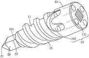
图1是本发明较佳实施例的分解图。Figure 1 is an exploded view of a preferred embodiment of the present invention.
图2是本发明较佳实施例的立体图。FIG. 2 is a perspective view of a preferred embodiment of the present invention.
图3是本发明较佳实施例缝合锚钉另一角度的立体图。FIG. 3 is a perspective view of another angle of the suture anchor according to the preferred embodiment of the present invention.
图4是本发明较佳实施例的剖面图。4 is a cross-sectional view of a preferred embodiment of the present invention.
图5是本发明较佳实施例于图4圈选处的放大图。FIG. 5 is an enlarged view of the preferred embodiment of the present invention at the circled part of FIG. 4 .
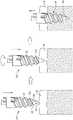
图6是本发明较佳实施例的使用实施示意图。FIG. 6 is a schematic diagram of the use and implementation of the preferred embodiment of the present invention.
图7是本发明另一较佳实施例的立体图。FIG. 7 is a perspective view of another preferred embodiment of the present invention.
图8是本发明另一较佳实施例的使用实施示意图。FIG. 8 is a schematic diagram of the use and implementation of another preferred embodiment of the present invention.
符号说明:Symbol Description:
10缝合锚钉 11锚钉本体10 Suture
12旋刃插孔 121刃角12
13穿线部 14穿线构造13 Threading
141穿线孔 142U形凹槽141
15螺牙构造 151入牙口15
152牙山 153牙底152 Asan 153 Tooth
20旋刃 21尖端部20
22刀刃 A圆形轨迹22 blades A circular trajectory
B骨骼 θ1旋转幅度B bone θ1 rotation amplitude
θ2夹角 θ3倾斜角θ2 included angle θ3 inclination angle
H1高度 H2宽度H1 height H2 width
H3宽度H3 width
具体实施方式Detailed ways
为能详细了解本发明的技术特征及实用功效,并可依照说明书的内容来实施,进一步以如图式所示的较佳实施例,详细说明如下。In order to understand the technical features and practical effects of the present invention in detail, and to implement it according to the contents of the description, the preferred embodiments shown in the drawings are further described in detail as follows.
如图1至图5所示的较佳实施例,本发明提供一种缝合锚钉系统,包括一缝合锚钉10以及一旋刃20,其中:1 to 5, the present invention provides a suture anchor system, comprising a
该缝合锚钉10设有一锚钉本体11,该锚钉本体11是直管状并具有前、后两端,于该锚钉本体11的轴心位置沿轴向贯穿一非圆形的旋刃插孔12,在本较佳实施例中该旋刃插孔12是以该锚钉本体11的轴心为中心的正方形孔,该旋刃插孔12于该锚钉本体11前端面的周围形成四个位于同一假想的圆形轨迹A的刃角121,该圆形轨迹A也以该锚钉本体11的轴心为中心,于该锚钉本体11的后端部形成一圆柱状且直径大于前侧的穿线部13,该旋刃插孔12的后端向后贯穿该穿线部13的中央,于该穿线部13形成一穿线构造 14,该穿线构造14是在该穿线部13后端面相反两侧各向前穿设一对穿线孔 141,配合各对穿线孔141于该穿线部13的外周面形成一U形凹槽142,各 U形凹槽142的两端与各对穿线孔141的内端相通。The
于该锚钉本体11的外周面形成一沿螺锁方向由后向前螺旋延伸的螺牙构造15,在本较佳实施例中该螺锁方向是顺时钟的方向,该螺牙构造15前端螺旋的幅度被削尖收窄,藉此于该锚钉本体11的前端面形成一入牙口151,该入牙口151的位置位于以该锚钉本体11的轴心为中心,沿该螺锁方向落后其中一刃角121旋转幅度θ1角度的位置,在本较佳实施例中该旋转幅度θ1 的角度为13度,如此使该入牙口151沿该螺锁方向旋转时能紧跟于该刃角121的后方;该螺牙构造15的截断面为梯形并且两侧之间的夹角θ2为50度,该螺牙构造15的截断面顶端与底端分别定义为一牙山152以及一牙底153,在本较佳实施例中该牙山152的表面是相较于该锚钉本体11轴心方向的倾斜角θ3为2至4度的倾斜面,较佳的该倾斜角θ3为3度,该螺牙构造15截断面垂直于该锚钉本体11轴心方向的高度H1为0.7mm,该牙山152沿该锚钉本体11轴心方向的宽度H2为0.6mm,该牙底沿该锚钉本体11轴心方向的宽度H3为1.2mm,该牙山152与该牙底153宽度尺寸的比值为0.5。A
该旋刃20是截断面形状配合该旋刃插孔的杆体,如本较佳实施例该旋刃 20是正方形的杆体,于该旋刃20的前端形成一尖端部21,该尖端部21是中央向前凸出形成尖端的正方形锥体,于该旋刃20周围的四个转角处分别形成一刀刃22,在本较佳实施例中该旋刃20的长度略长于该锚钉本体11的长度,使得该旋刃20穿置于该缝合锚钉10的旋刃插孔12时,该旋刃20周围四个刀刃22的前端部分与该尖端部21会向前穿出该旋刃插孔12,该旋刃20通过非圆形的截断面穿置于该缝合锚钉10的非圆形且形状符合的旋刃插孔12 内,使得旋转该旋刃20时可一并驱动该缝合锚钉10旋转。The
本发明除前述较佳实施例,是将该旋刃插孔12以及该旋刃20设为正方形配合的形状以外,也可将非圆形的形状设为星形、三角形、五边形或六边形等其他多边形的形状,这时该旋刃20的尖端部21的锥状以及各刀刃22的数量亦随之变化,只要周边的多个刃角121能位于同一假想的圆形轨迹A即可;并且该旋转幅度θ1可为10至15度之间的角度,该螺牙构造15的高度 H1可为0.6至0.9mm,该牙山152的宽度H2可为0.4至0.7mm,该牙底153 的宽度H3可为1.1至1.3mm,只要该牙山152与该牙底153宽度尺寸的比值为0.5即可,藉此使得本发明的螺牙构造15为较三角形齿更趋近方形齿的构造;该穿线构造14也可为仅于该穿线部13的后端面穿设一对穿线孔141而与一U形凹槽142相通的构造,或者该穿线构造14也可以改设为于该锚钉本体11后端部周围设有的开口,此开口与该旋刃插孔12相通,这时该旋刃 20配合此开口于其周面形成一道延伸至前端露出该缝合锚钉10的直线沟槽,使缝线可由该开口穿入并由该直线沟槽的前端穿出,于该缝合锚钉10锁入骨骼时缝线能绞合于该螺牙构造15与骨骼之间。In addition to the above-mentioned preferred embodiment of the present invention, the rotating
当前述较佳实施例使用时,如图6所示,是以该旋刃20配合将该缝合锚钉10植入人体的骨骼B内;操作时该旋刃20的后端是附接于提供医师手持的器械例如握把等手持装置,接着医师将该尖端部21对准敲入该骨骼B预定植入该缝合锚钉10处,接着转动该旋刃20以其周围的刀刃22在该骨骼B 切削出圆形的导孔,同时带动该缝合锚钉10同步转动,以该螺牙构造15的入牙口151开始螺锁入该旋刃20作为前导切削出的圆形导孔中,配合该入牙口151是以落后的方式接邻于其中一刀刃22的设计,使得该螺牙构造15钻入导孔的过程会更加顺利,当该缝合锚钉10螺锁至该骨骼B的预定深度后,抽出该旋刃20即完成植入该缝合锚钉10的操作。When the aforementioned preferred embodiment is used, as shown in FIG. 6, the
本发明以截面积较圆形轨迹A小却能挖出相同大小导孔的旋刃20驱动该缝合锚钉10,使该缝合锚钉10的旋刃插孔12能设计为较小的孔洞,能缩减该缝合锚钉10整体的设计体积,减少植入骨骼B时破坏周边组织的程度。并且由于该旋刃20切削导孔同时该缝合锚钉10亦螺锁入导孔内,使得医师可省去预先凿孔的麻烦,且该螺牙构造15由于是两侧之间的夹角θ2为50度的近似方形齿的构造,相较于三角形齿接触骨骼B的面积更大,因此该缝合锚钉10植入固定时更加牢靠、稳固。In the present invention, the
请参看图7、图8所示的本发明另一较佳实施例,是将该旋刃20的长度设为该缝合锚钉10两倍的长度,该旋刃20后半部穿设于该缝合锚钉10的该旋刃插孔12并且前半部向前穿出该旋刃插孔12。Please refer to another preferred embodiment of the present invention shown in FIG. 7 and FIG. 8 , the length of the
此本发明另一较佳实施例使用时,是执行一植入方法,如图8所示,是将该缝合锚钉10留置于该旋刃20周围的后半段,敲击该旋刃20后端附接的器械例如握把,以该旋刃20的尖端部21直进的方式,利用该旋刃20的前半段于该骨骼B凿出与该缝合锚钉10等长的凿孔,接着向后至少抽回该旋刃 20向前穿出该缝合锚钉10除尖端部21以外的部分,仅剩下该尖端部21露出该缝合锚钉10前端,再转动该旋刃20带动该缝合锚钉10旋转,这时该螺牙构造15旋转并以其前端的入牙口151由该旋刃20的其中一刀刃22所凿出的凿孔一角开始攻入该凿孔,过程中该旋刃20仅负担驱动该缝合锚钉10的作用而不用于挖孔,将该缝合锚钉10持续钻入直至预定深度,最后将该旋刃 20由该缝合锚钉10内完全抽出,即完成该缝合锚钉10的植入操作。When another preferred embodiment of the present invention is used, an implantation method is performed, as shown in FIG. An instrument such as a handle attached to the rear end uses the front half of the
本发明另一较佳实施例植入的方法,除了与前述较佳实施例所述同样具有令医师可省去预先凿孔的麻烦,以及该螺牙构造15接触骨骼B的面积大,因此该缝合锚钉10植入固定时更加牢靠、稳固的功效以外,由于该缝合锚钉 10螺锁入该骨骼B的过程中,该螺牙构造15是由截面积较小的凿孔螺锁入该骨骼B内,因此该缝合锚钉10植入该骨骼B过程当中所破坏的周边组织更少,需要自行挖开凿孔周围的骨骼部分更多,令该缝合锚钉10植入骨骼B的固定构造更为紧密稳固,且手术后愈合的效果更佳。The implantation method according to another preferred embodiment of the present invention has the same advantages as the above-mentioned preferred embodiment, so that the physician can save the trouble of pre-drilling holes, and the area of the
以上所述仅为本发明的较佳实施例而已,并非用以限定本发明主张的权利范围,凡其它未脱离本发明所揭示的精神所完成的等效改变或修饰,均应包括在本发明的权利要求内。The above descriptions are only preferred embodiments of the present invention, and are not intended to limit the scope of rights claimed by the present invention. All other equivalent changes or modifications that do not depart from the spirit disclosed in the present invention shall be included in the present invention. within the claims.
Claims (10)
Priority Applications (1)
| Application Number | Priority Date | Filing Date | Title |
|---|---|---|---|
| CN202011404235.9ACN114601515A (en) | 2020-12-04 | 2020-12-04 | Suture anchor, system and implantation method thereof |
Applications Claiming Priority (1)
| Application Number | Priority Date | Filing Date | Title |
|---|---|---|---|
| CN202011404235.9ACN114601515A (en) | 2020-12-04 | 2020-12-04 | Suture anchor, system and implantation method thereof |
Publications (1)
| Publication Number | Publication Date |
|---|---|
| CN114601515Atrue CN114601515A (en) | 2022-06-10 |
Family
ID=81855793
Family Applications (1)
| Application Number | Title | Priority Date | Filing Date |
|---|---|---|---|
| CN202011404235.9APendingCN114601515A (en) | 2020-12-04 | 2020-12-04 | Suture anchor, system and implantation method thereof |
Country Status (1)
| Country | Link |
|---|---|
| CN (1) | CN114601515A (en) |
Citations (7)
| Publication number | Priority date | Publication date | Assignee | Title |
|---|---|---|---|---|
| WO2010062379A1 (en)* | 2008-11-25 | 2010-06-03 | Sonoma Orthopedic Products, Inc. | Bone fracture fixation screws, systems and methods of use |
| CN103169512A (en)* | 2013-03-26 | 2013-06-26 | 雷青 | Multi-thread-hole ground anchor used for soft tissue repair and fixing |
| CN203328748U (en)* | 2013-04-16 | 2013-12-11 | 创生医疗器械(中国)有限公司 | Anchor suturing system |
| CN203953727U (en)* | 2014-07-10 | 2014-11-26 | 浙江科惠医疗器械有限公司 | A kind of fixing holdfast of soft tissue repair of suitable implantation spongy bone |
| CN209203377U (en)* | 2018-11-29 | 2019-08-06 | 北京天星博迈迪医疗器械有限公司 | A kind of soft tissue fixing belt line holdfast |
| TWM599147U (en)* | 2020-04-27 | 2020-08-01 | 鐿鈦科技股份有限公司 | Anchor implantation system |
| CN214017667U (en)* | 2020-12-04 | 2021-08-24 | 镱钛科技股份有限公司 | Suture anchor and its system |
- 2020
- 2020-12-04CNCN202011404235.9Apatent/CN114601515A/enactivePending
Patent Citations (7)
| Publication number | Priority date | Publication date | Assignee | Title |
|---|---|---|---|---|
| WO2010062379A1 (en)* | 2008-11-25 | 2010-06-03 | Sonoma Orthopedic Products, Inc. | Bone fracture fixation screws, systems and methods of use |
| CN103169512A (en)* | 2013-03-26 | 2013-06-26 | 雷青 | Multi-thread-hole ground anchor used for soft tissue repair and fixing |
| CN203328748U (en)* | 2013-04-16 | 2013-12-11 | 创生医疗器械(中国)有限公司 | Anchor suturing system |
| CN203953727U (en)* | 2014-07-10 | 2014-11-26 | 浙江科惠医疗器械有限公司 | A kind of fixing holdfast of soft tissue repair of suitable implantation spongy bone |
| CN209203377U (en)* | 2018-11-29 | 2019-08-06 | 北京天星博迈迪医疗器械有限公司 | A kind of soft tissue fixing belt line holdfast |
| TWM599147U (en)* | 2020-04-27 | 2020-08-01 | 鐿鈦科技股份有限公司 | Anchor implantation system |
| CN214017667U (en)* | 2020-12-04 | 2021-08-24 | 镱钛科技股份有限公司 | Suture anchor and its system |
Similar Documents
| Publication | Publication Date | Title |
|---|---|---|
| US10966768B2 (en) | Method of installing self-drilling, self-tapping bone screw for bicortical purchase | |
| US5098435A (en) | Cannula | |
| US9861416B2 (en) | Bone fixation screw and method | |
| CN110831531B (en) | Angled grooves in cannulated bone screws | |
| US5354299A (en) | Method of revising a screw in a tunnel | |
| US6884245B2 (en) | Hardware for cutting bone cores | |
| CN101422381B (en) | Double thread hollow suture anchor | |
| US7749225B2 (en) | Surgical instrumentation and method for forming a passage in bone having an enlarged cross-sectional portion | |
| US7641677B2 (en) | Compression bone fragment wire | |
| US6547561B2 (en) | Disposable anesthesia delivery system with shortened outer sleeve and inner hollow drill | |
| US7731738B2 (en) | Cannulated screw | |
| US9216036B2 (en) | Tissue anchor insertion system | |
| JP6388220B2 (en) | Perforated trocar | |
| US20230397940A1 (en) | Bone screw with cutting tip | |
| US20090048575A1 (en) | Trocar with obturator having longitudinal through holes for guiding wires | |
| TWI763162B (en) | Suture anchor, system and implantation method therefor | |
| US20100196849A1 (en) | Flapless dental implant punch | |
| CN214017667U (en) | Suture anchor and its system | |
| TWM610407U (en) | Seam anchor nail and system thereof | |
| CN114601515A (en) | Suture anchor, system and implantation method thereof | |
| WO1990004364A1 (en) | Intraosseous needle assembly | |
| CN212281473U (en) | Anchor Implantation System | |
| TWI723854B (en) | Anchor implantation system | |
| TWM599147U (en) | Anchor implantation system | |
| EP4243724B1 (en) | A dental implant implantable without a previous perforation of bone |
Legal Events
| Date | Code | Title | Description |
|---|---|---|---|
| PB01 | Publication | ||
| PB01 | Publication | ||
| SE01 | Entry into force of request for substantive examination | ||
| SE01 | Entry into force of request for substantive examination | ||
| WD01 | Invention patent application deemed withdrawn after publication | Application publication date:20220610 | |
| WD01 | Invention patent application deemed withdrawn after publication |