CN114599587A - Spacecraft - Google Patents
SpacecraftDownload PDFInfo
- Publication number
- CN114599587A CN114599587ACN201980101643.6ACN201980101643ACN114599587ACN 114599587 ACN114599587 ACN 114599587ACN 201980101643 ACN201980101643 ACN 201980101643ACN 114599587 ACN114599587 ACN 114599587A
- Authority
- CN
- China
- Prior art keywords
- spacecraft
- amplifier
- reflector
- main body
- frequency band
- Prior art date
- Legal status (The legal status is an assumption and is not a legal conclusion. Google has not performed a legal analysis and makes no representation as to the accuracy of the status listed.)
- Granted
Links
Images


Classifications
- B—PERFORMING OPERATIONS; TRANSPORTING
- B64—AIRCRAFT; AVIATION; COSMONAUTICS
- B64G—COSMONAUTICS; VEHICLES OR EQUIPMENT THEREFOR
- B64G1/00—Cosmonautic vehicles
- B64G1/22—Parts of, or equipment specially adapted for fitting in or to, cosmonautic vehicles
- B64G1/24—Guiding or controlling apparatus, e.g. for attitude control
- B64G1/36—Guiding or controlling apparatus, e.g. for attitude control using sensors, e.g. sun-sensors, horizon sensors
- B—PERFORMING OPERATIONS; TRANSPORTING
- B64—AIRCRAFT; AVIATION; COSMONAUTICS
- B64G—COSMONAUTICS; VEHICLES OR EQUIPMENT THEREFOR
- B64G1/00—Cosmonautic vehicles
- B64G1/10—Artificial satellites; Systems of such satellites; Interplanetary vehicles
- B64G1/1007—Communications satellites
- B—PERFORMING OPERATIONS; TRANSPORTING
- B64—AIRCRAFT; AVIATION; COSMONAUTICS
- B64G—COSMONAUTICS; VEHICLES OR EQUIPMENT THEREFOR
- B64G1/00—Cosmonautic vehicles
- B64G1/10—Artificial satellites; Systems of such satellites; Interplanetary vehicles
- B64G1/1021—Earth observation satellites
- B64G1/1035—Earth observation satellites using radar for mapping, surveying or detection, e.g. of intelligence
- B—PERFORMING OPERATIONS; TRANSPORTING
- B64—AIRCRAFT; AVIATION; COSMONAUTICS
- B64G—COSMONAUTICS; VEHICLES OR EQUIPMENT THEREFOR
- B64G1/00—Cosmonautic vehicles
- B64G1/22—Parts of, or equipment specially adapted for fitting in or to, cosmonautic vehicles
- B64G1/66—Arrangements or adaptations of apparatus or instruments, not otherwise provided for
- G—PHYSICS
- G01—MEASURING; TESTING
- G01S—RADIO DIRECTION-FINDING; RADIO NAVIGATION; DETERMINING DISTANCE OR VELOCITY BY USE OF RADIO WAVES; LOCATING OR PRESENCE-DETECTING BY USE OF THE REFLECTION OR RERADIATION OF RADIO WAVES; ANALOGOUS ARRANGEMENTS USING OTHER WAVES
- G01S13/00—Systems using the reflection or reradiation of radio waves, e.g. radar systems; Analogous systems using reflection or reradiation of waves whose nature or wavelength is irrelevant or unspecified
- G01S13/88—Radar or analogous systems specially adapted for specific applications
- G01S13/89—Radar or analogous systems specially adapted for specific applications for mapping or imaging
- G01S13/90—Radar or analogous systems specially adapted for specific applications for mapping or imaging using synthetic aperture techniques, e.g. synthetic aperture radar [SAR] techniques
- G—PHYSICS
- G01—MEASURING; TESTING
- G01S—RADIO DIRECTION-FINDING; RADIO NAVIGATION; DETERMINING DISTANCE OR VELOCITY BY USE OF RADIO WAVES; LOCATING OR PRESENCE-DETECTING BY USE OF THE REFLECTION OR RERADIATION OF RADIO WAVES; ANALOGOUS ARRANGEMENTS USING OTHER WAVES
- G01S7/00—Details of systems according to groups G01S13/00, G01S15/00, G01S17/00
- G01S7/02—Details of systems according to groups G01S13/00, G01S15/00, G01S17/00 of systems according to group G01S13/00
- G01S7/027—Constructional details of housings, e.g. form, type, material or ruggedness
- G—PHYSICS
- G01—MEASURING; TESTING
- G01S—RADIO DIRECTION-FINDING; RADIO NAVIGATION; DETERMINING DISTANCE OR VELOCITY BY USE OF RADIO WAVES; LOCATING OR PRESENCE-DETECTING BY USE OF THE REFLECTION OR RERADIATION OF RADIO WAVES; ANALOGOUS ARRANGEMENTS USING OTHER WAVES
- G01S7/00—Details of systems according to groups G01S13/00, G01S15/00, G01S17/00
- G01S7/02—Details of systems according to groups G01S13/00, G01S15/00, G01S17/00 of systems according to group G01S13/00
- G01S7/03—Details of HF subsystems specially adapted therefor, e.g. common to transmitter and receiver
- H—ELECTRICITY
- H01—ELECTRIC ELEMENTS
- H01Q—ANTENNAS, i.e. RADIO AERIALS
- H01Q1/00—Details of, or arrangements associated with, antennas
- H01Q1/27—Adaptation for use in or on movable bodies
- H01Q1/28—Adaptation for use in or on aircraft, missiles, satellites, or balloons
- H01Q1/288—Satellite antennas
- H—ELECTRICITY
- H01—ELECTRIC ELEMENTS
- H01Q—ANTENNAS, i.e. RADIO AERIALS
- H01Q15/00—Devices for reflection, refraction, diffraction or polarisation of waves radiated from an antenna, e.g. quasi-optical devices
- H01Q15/14—Reflecting surfaces; Equivalent structures
- H01Q15/16—Reflecting surfaces; Equivalent structures curved in two dimensions, e.g. paraboloidal
- H01Q15/161—Collapsible reflectors
- H01Q15/162—Collapsible reflectors composed of a plurality of rigid panels
- H—ELECTRICITY
- H01—ELECTRIC ELEMENTS
- H01Q—ANTENNAS, i.e. RADIO AERIALS
- H01Q19/00—Combinations of primary active antenna elements and units with secondary devices, e.g. with quasi-optical devices, for giving the antenna a desired directional characteristic
- H01Q19/10—Combinations of primary active antenna elements and units with secondary devices, e.g. with quasi-optical devices, for giving the antenna a desired directional characteristic using reflecting surfaces
- H01Q19/12—Combinations of primary active antenna elements and units with secondary devices, e.g. with quasi-optical devices, for giving the antenna a desired directional characteristic using reflecting surfaces wherein the surfaces are concave
- H01Q19/13—Combinations of primary active antenna elements and units with secondary devices, e.g. with quasi-optical devices, for giving the antenna a desired directional characteristic using reflecting surfaces wherein the surfaces are concave the primary radiating source being a single radiating element, e.g. a dipole, a slot, a waveguide termination
- H—ELECTRICITY
- H01—ELECTRIC ELEMENTS
- H01Q—ANTENNAS, i.e. RADIO AERIALS
- H01Q19/00—Combinations of primary active antenna elements and units with secondary devices, e.g. with quasi-optical devices, for giving the antenna a desired directional characteristic
- H01Q19/10—Combinations of primary active antenna elements and units with secondary devices, e.g. with quasi-optical devices, for giving the antenna a desired directional characteristic using reflecting surfaces
- H01Q19/18—Combinations of primary active antenna elements and units with secondary devices, e.g. with quasi-optical devices, for giving the antenna a desired directional characteristic using reflecting surfaces having two or more spaced reflecting surfaces
- H01Q19/19—Combinations of primary active antenna elements and units with secondary devices, e.g. with quasi-optical devices, for giving the antenna a desired directional characteristic using reflecting surfaces having two or more spaced reflecting surfaces comprising one main concave reflecting surface associated with an auxiliary reflecting surface
- B—PERFORMING OPERATIONS; TRANSPORTING
- B64—AIRCRAFT; AVIATION; COSMONAUTICS
- B64G—COSMONAUTICS; VEHICLES OR EQUIPMENT THEREFOR
- B64G1/00—Cosmonautic vehicles
- B64G1/22—Parts of, or equipment specially adapted for fitting in or to, cosmonautic vehicles
- B64G1/222—Parts of, or equipment specially adapted for fitting in or to, cosmonautic vehicles for deploying structures between a stowed and deployed state
Landscapes
- Engineering & Computer Science (AREA)
- Remote Sensing (AREA)
- Physics & Mathematics (AREA)
- General Physics & Mathematics (AREA)
- Radar, Positioning & Navigation (AREA)
- Astronomy & Astrophysics (AREA)
- Aviation & Aerospace Engineering (AREA)
- Computer Networks & Wireless Communication (AREA)
- Electromagnetism (AREA)
- Evolutionary Computation (AREA)
- Chemical & Material Sciences (AREA)
- Combustion & Propulsion (AREA)
- Aerials With Secondary Devices (AREA)
- Details Of Aerials (AREA)
Abstract
Translated fromChinese
Description
Translated fromChinese技术领域technical field
本公开涉及能够向外部发射电波的航天器,其中,该电波包含规定的频段的频率。The present disclosure relates to a spacecraft capable of transmitting radio waves to the outside, wherein the radio waves include frequencies in a predetermined frequency band.
背景技术Background technique
以往,在人造卫星等航天器中,向外部发射电波,用于与地面站的通信或数据观测的用途。专利文献1记载了一种包含卫星搭载用微波发送装置的卫星,该卫星搭载用微波发送装置具有输入所生成的微波信号的天线喇叭和将微波信号向地面发射的天线。在这种卫星中,为了实现高输出电力,一直以来使用用于在输入给天线喇叭之前对所生成的微波信号进行放大的高输出电力放大器。Conventionally, in spacecraft such as artificial satellites, radio waves are emitted to the outside for communication with ground stations or for data observation.
现有技术文献prior art literature
专利文献Patent Literature
专利文献1:日本特开2012-207981号公报Patent Document 1: Japanese Patent Laid-Open No. 2012-207981
发明内容SUMMARY OF THE INVENTION
发明要解决的课题The problem to be solved by the invention
因此,鉴于上述那样的技术,在本公开中,通过各种实施方式来提供采用了更有效的放大器配置的航天器。Therefore, in view of the techniques described above, in the present disclosure, various embodiments provide a spacecraft employing a more efficient amplifier configuration.
用于解决课题的手段Means for solving problems
根据本公开的一个方式,提供了一种航天器,其包含:主体,其在内部具有用于收纳电子设备的收纳空间;振荡器,其构成为输出包含规定的频段的频率的电波;放大器,其配置于所述主体的外部封装从而暴露在宇宙空间中,并构成为对由所述振荡器输出的所述电波的电力进行放大;以及天线,其配置于所述主体的外部封装,用于以由所述放大器放大后的电力将所述电波向外部发射。According to one aspect of the present disclosure, there is provided a spacecraft including: a main body having a storage space for accommodating electronic equipment inside; an oscillator configured to output a radio wave including a frequency of a predetermined frequency band; and an amplifier, It is arranged on the outer package of the main body so as to be exposed to space, and is configured to amplify the electric power of the radio wave output from the oscillator; and an antenna is arranged on the outer package of the main body and used for The radio waves are radiated to the outside with the electric power amplified by the amplifier.
发明效果Invention effect
本公开的各种实施方式能够提供采用了更有效的放大器配置的航天器。Various embodiments of the present disclosure can provide spacecraft that employ more efficient amplifier configurations.
另外,上述效果仅是为了便于说明的例示,并不是限定。在上述效果的基础上,或者代替上述效果,也能够实现本公开所记载的任何效果或者对于本领域技术人员而言显而易见的效果。In addition, the said effect is only an illustration for convenience of description, and it is not restrictive. In addition to or in place of the above-described effects, any effects described in the present disclosure or effects obvious to those skilled in the art can also be achieved.
附图说明Description of drawings
图1是示出本公开的第1实施方式的航天器1的结构概要的图。FIG. 1 is a diagram showing an outline of the configuration of a
图2是示出本公开的第1实施方式的航天器1的结构的框图。FIG. 2 is a block diagram showing the configuration of the
图3是示出本公开的第1实施方式的发送器110的结构的框图。FIG. 3 is a block diagram showing the configuration of the
图4是示出本公开的第1实施方式的航天器1的结构概要的侧视图。FIG. 4 is a side view showing the outline of the configuration of the
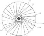
图5是示出本公开的第1实施方式的航天器1的结构概要的俯视图。FIG. 5 is a plan view showing an outline of the configuration of the
图6是示出本公开的第1实施方式的放大器112的结构概要的侧视图。FIG. 6 is a side view showing the outline of the configuration of the
图7是示出本公开的第1实施方式的放大器112的结构概要的俯视图。FIG. 7 is a plan view showing the outline of the configuration of the
具体实施方式Detailed ways
参照附图对本公开的各种实施方式进行说明。另外,对附图中共通的构成要素标注相同的参照标号。Various embodiments of the present disclosure will be described with reference to the accompanying drawings. In addition, the same reference numerals are attached to the common components in the drawings.
<第1实施方式><First Embodiment>
1.航天器1的结构1. Structure of Spacecraft 1
图1是示出本公开的第1实施方式的航天器1的结构概要的图。根据图1,航天器1包含:主体300,其搭载有控制单元等设备,该控制单元在宇宙空间中进行航天器1自身的航行的控制、航天器1的动作和姿态的控制;电源单元200,其提供用于在宇宙空间中对包括控制单元、通信单元100在内的各种构成要素进行驱动的电力;以及通信单元100,其用于朝向航天器1以及存在地面或其他航天器等的外部宇宙空间发射电波,并且从宇宙空间接收电波。FIG. 1 is a diagram showing an outline of the configuration of a
在本实施方式中,作为一例,航天器1能够用作用于搭载SAR(合成孔径雷达)的小型SAR卫星。这样的小型SAR卫星可以用于通过向观测对象物发射微波、毫米波或亚毫米波频段的电波并接收来自该观测对象物的反射波而进行观测对象物的观测和分析等。这里,在接收来自观测对象物的反射波的SAR雷达中,要求高输出电力,因此需要搭载电力的放大器。该放大器生成高输出电力,因此可能成为非常大的热源。因此,特别是在将航天器1用作小型SAR卫星的情况下,如何高效地使来自放大器的热散发非常重要。另一方面,在小型SAR卫星中,需要将包括放大器在内的电子部件配置在有限的收纳空间中,因此,在考虑了散热效果的基础上高效地配置电子部件更为重要。In the present embodiment, as an example, the
另外,以下,对将图1所示的航天器1用作小型SAR卫星的情况进行说明。但是,本实施方式不限于用作小型SAR卫星的情况,也可以用于其他用途、其他方式(大型卫星)等。In addition, below, the case where the
主体300在内部具有用于收纳各种电子设备和机构部件的收纳空间(未图示)。作为一例,主体300由俯视时具有六边形形状的八面体形成,并形成为中空状以在该主体300的内部构成收纳空间。但是,关于该主体300的形状,只要能够在其内部形成收纳空间即可,也可以是其他多面体及球体等任意形状。另外,以下,对主体300形成为俯视时具有六边形形状的八面体状的情况进行说明。The
在形成于主体300的内部的收纳空间中收纳有计算机301、传感器330、致动器340、电源控制电路201、电池220、通信控制电路170等各种电子部件及用于将它们电连接起来的布线类。Various electronic components such as the
作为电源单元200,在本实施方式中,包含太阳能面板230。作为一例,该太阳能面板230以覆盖主体300的外表面的方式配置于主体300的壁面。通过这样配置,能够有效利用主体300的壁面。As the
通信单元100除了包含发送器110之外,还包含:辐射器120;副反射器(副反射镜)131,其配置为以规定的角度与辐射器120对置,该副反射器131用于将从辐射器120发射的电波向主反射器132反射;作为主反射镜的主反射器132,其配置为与副反射器131的镜面对置,对被副反射器131反射的电波进一步进行反射而将电波向外部发射;以及支承杆135,其用于支承副反射器131。In addition to the
主反射器132包含毂139、多个肋136、面状体137等。主反射器132的反射面形成为抛物面形状,以如上述那样作为主反射镜而发挥功能。The
毂139设置在主反射器132的中心部的天线轴线X(也称为毂139的中心轴线X)上且主体300的配置有副反射器131的一侧。作为一例,毂139使用塑料等电介质或者钛、不锈钢等金属而形成为大致圆柱状。该毂139以中心轴线X为中心在其外周面上按照规定的间隔呈放射状地配设有多个肋136。即,毂139的截面形状(从沿着上述中心轴线X的方向进行观察的情况下的截面形状)为圆形形状,但该形状也可以形成为椭圆形形状或多边形形状中的任意形状。The
肋136包含多个肋。各肋136以毂139为中心按照规定的间隔呈放射状地配设于毂139的外周。各肋136的作为反射镜面的一侧的上表面形成为抛物面形状。而且,在形成为抛物面形状的上表面上架设有面状体137。作为一例,肋136是由不锈钢弹簧钢、GFRP(GlassFiber Reinforced Plastics:玻璃纤维增强塑料)、CFRP(Carbon Fiber ReinforcedPlastics:碳纤维复合材料)等复合材料形成的弹簧件,具有弹性。
另外,在本实施方式中,肋136由全部24个肋构成。但是,肋136可以根据展开天线展开时的面积、所使用的肋的材质和强度等来变更其个数,与偶数或奇数无关。另外,在本实施方式中,肋136按照规定的间隔配设,但关于该间隔,可以在全部的肋136中采用恒定的间隔,也可以仅使一部分的间隔变密,也可以是不规则的。In addition, in this embodiment, the
与肋136一同构成主反射器132的面状体137架设在彼此相邻的一对肋136之间。面状体137使用能够反射电波的材料而形成为整体上呈抛物面形状。作为一例,面状体137由金属的网状体(金属网)形成,该金属由钼、金或它们的组合形成。在本实施方式中,面状体137是根据肋136的数量来准备大致三角形形状的金属网,将各金属网缝合并架设于肋136的形成为抛物面形状的上表面上的。A
副反射器131与主反射器132对置配置,该副反射器131的下表面侧(与主反射器132对应的一侧)被支承杆135支承。通过支承杆135而将副反射器131与配置在其中心轴线X的线上的辐射器120分开规定的距离地配置。副反射器131与主反射器132的面状体137同样地使用能够反射电波的材料构成,具有整体上朝向主反射器132的面的二次曲面形状。而且,副反射器131将从辐射器120辐射出的电波朝向主反射器132反射。因此,副反射器131与辐射器120和主反射器132分开规定的距离而配置。The sub-reflector 131 is arranged to face the
配置支承杆135是为了将副反射器131与辐射器120和主反射器132分开规定的距离地配置。支承杆135包含:第1支承杆133,其一端与副反射器131连接,另一端与接头138连接;以及第2支承杆134,其一端与接头138连接,另一端与主体连接。通过第1支承杆133和第2支承杆134来支承与第1支承杆133的一端连接的副反射器131。支承杆135由1根杆或多根杆构成,以支承副反射器131。在图1的例子中,3对支承杆135(其中1对在背面被覆盖而未图示)等间隔配置。另外,在图1的例子中,对第1支承杆133和第2支承杆134作为一对杆的方式进行了说明。但是,不限于此,也可以相对于第1支承杆133减少或增加第2支承杆134的根数。The
另外,在本实施方式中,作为航天器1,对具有主反射器132形成为抛物面形状的卡塞格林天线(Cassegrain antenna)的小型SAR卫星的情况进行说明。但是,不限于此,也可以具有格雷戈里天线(Gregorian antenna)等其他抛物面天线或平面天线。In addition, in the present embodiment, as the
图2是示出本公开的第1实施方式的航天器1的结构的框图。航天器1无需具备图2所示的全部构成要素,也可以采用省略了一部分的结构,也可以添加其他构成要素。例如,航天器1也可以搭载多个电源单元200和/或多个通信单元100。FIG. 2 is a block diagram showing the configuration of the
根据图2,航天器1包含控制单元、电源单元200以及通信单元100,该控制单元包含存储器310、处理器320以及传感器330,该电源单元200包含电源控制电路210、电池220以及太阳能面板230,该通信单元100包含通信控制电路170、发送器110、接收器140、辐射器120、反射器130。该各构成要素经由控制线和数据线而彼此电连接。According to FIG. 2 , the
存储器310由RAM、ROM、非易失性存储器、HDD等构成,作为存储部而发挥功能。存储器310存储用于本实施方式的航天器1的各种控制的指示命令作为程序。作为一例,存储器310适当地存储有由照相机(未图示)拍摄到的航天器1的外部的图像、将通信单元100用作雷达而获得的观测值、经由通信单元100从地面站接收到的信息或者经由通信单元100向地面站发送的信息、航天器1的姿态和行进控制所需的传感器330等的检测信息等。The
处理器320作为根据存储于存储器310中的程序来进行航天器1的控制的控制部而发挥功能。具体而言,根据存储于存储器310中的程序而进行电源单元200、通信单元100、传感器330等的控制。作为一例,进行与生成用于经由通信单元100向地面站或其他航天器发送的信息、通过将通信单元100用作雷达向观测对象发射电波并接收其反射波而进行的观测相关的控制等。The
作为一例,传感器330可以包含航天器1的行进和姿态的控制所需的陀螺仪传感器、加速度传感器、位置传感器、速度传感器、恒星传感器等、用于观测航天器1的外部环境的温度传感器、照度传感器、红外线传感器等、用于测量航天器1的内部环境的温度传感器、照度传感器等。检测到的信息和数据适当地存储于存储器310中,用于处理器320的控制,或者经由通信单元100发送给地面的基站。As an example, the
作为一例,致动器340可以包含磁力矩器、反作用轮、CMG(control moment gyro:控制力矩陀螺)等。致动器340接收来自处理器320的指示命令,用于获得用于对航天器1进行姿态控制的扭矩或推力,作为推进部而发挥功能。As an example, the
电源单元200包含电源控制电路210、电池220以及太阳能面板230,作为电源部而发挥功能。电源控制电路210与电池220连接,对电池220的电力的充放进行控制。电池220接受电源控制电路210的控制,充入由太阳能面板230生成的电力,并且蓄积向主体300内的计算机301、通信单元100等各驱动系统提供的电力。The
通信单元100包含通信控制电路170、发送器110、接收器140、辐射器120以及反射器130,作为通信部而发挥功能。通信控制电路170为了经由所连接的辐射器120相对于地面站或其他航天器收发信息而进行信号的编码和解码等处理。发送器110包含振荡器、放大器等,通过放大器来放大由振荡器生成的具有规定的频段的频率的电波。放大后的电波经由辐射器120而发射到反射器130的反射面。在本实施方式中,通信单元100用于向观测对象发射电波并使用其反射波进行观测。因此,从辐射器120发射出的电波先被构成反射器130的副反射器131反射,再被主反射器132向外部发射。另一方面,从外部接收到的反射波通过相反的路径被接收器140接收。The
在本实施方式中,作为通信单元100,仅记载了具有副反射器131和主反射器132这一对反射器的通信单元。该通信单元100可以根据期望进行调整,以包含8GHz以下的频段、8GHz~12GHz频段(所谓的X频段)、12GHz~18GHz频段(所谓的Ku频段)等微波频段、30GHz以上的毫米波频段、300GHz以上的亚毫米波频段等频率。In the present embodiment, as the
图3是示出本公开的第1实施方式的发送器110的结构的框图。具体而言,图3是功能性地示出图2所示的发送器110的内部结构的图。根据图3,发送器110包含振荡器111、放大器112、合成器113以及低通滤波器114。FIG. 3 is a block diagram showing the configuration of the
作为一例,振荡器111在图1中配置于主体300的内部。振荡器111输出作为用于传送信号等的电波的高频信号。在本实施方式中,振荡器111输出电波,该电波包含8GHz以下的频段、8GHz~12GHz频段(所谓的X频段)、12GHz~18GHz频段(所谓的Ku频段)等微波频段、30GHz以上的毫米波频段、300GHz以上的亚毫米波频段的频率中的至少任意频率,优选包含8GHz以下的频段、8GHz~12GHz频段(所谓的X频段)、12GHz~18GHz频段(所谓的Ku频段)等微波频段的频率中的至少任意频率,更优选包含8GHz~12GHz频段(所谓的X频段)的频率中的至少任意频率。As an example, the
放大器112与振荡器111电连接,对从振荡器111输出的电波的电力进行放大。在本实施方式中,作为一例,通过朝向外部的观测对象发射电波并接收被该观测对象反射的反射波而进行观测对象的数据的观测。因此,需要非常高的发送电力。在本实施方式中,放大器112进行放大,以成为500W~5,000W的电力,优选成为700W~2,500W的发送电力,更优选成为1,000W~1,500W的发送电力。可以根据该输出将1个或多个放大器组合来构成放大器112。该放大器112的具体结构在后文描述。另外,放大器的输出仅是一例。例如,各范围的上限和下限仅是规定了当前所需的电力,不论是超过该上限的输出还是低于下限的输出,通过应用本实施方式的结构,当然都能够得到散热效果等期望的效果。The
在将多个放大器组合来构成放大器112的情况下,合成器113与放大器112电连接,该合成器113将从各放大器输出的电波合成为一个载波。低通滤波器114与合成器113电连接,该低通滤波器114用于从合成器113输出的电波中仅取出低频成分并将其去除。这是为了去除例如由于电波法等而其使用被限制的频段的电波。通过了低通滤波器114后的电波输出给图2所示的辐射器120,经由辐射器120向外部发射。When the
这里,如上所述,发送器110所包含的放大器112使用高输出电力放大器。因此,放大器112会由于工作而散发热量,给周围的电子设备带来不良影响。进而,当放大器112成为高温时,构成放大器112的元件自身也发生故障等的风险变高。因此,在本实施方式中,放大器112配置于主体300的外部封装部分,暴露在宇宙空间中。这样,能够远离处理器320等收纳于主体300的内部的收纳空间中的其他电子设备,能够减轻对其他电子设备的不良影响。另外,在航天器1在卫星轨道上环绕那样的情况下,由于放大器112暴露在宇宙空间中,从而也能够有效地进行冷却。Here, as described above, the
图4是示出本公开的第1实施方式的航天器1的结构概要的侧视图。具体而言,图4是为了示出放大器112的配置位置而省略了主反射器132的一部分结构的图。另外,图5是示出本公开的第1实施方式的航天器1的结构概要的俯视图。具体而言,图5是为了示出放大器112的配置位置而省略了副反射器131的一部分结构的图。FIG. 4 is a side view showing the outline of the configuration of the
首先,根据图4,在由上表面和底面具有六边形的八面体构成的主体300的上表面上配置有毂139,该毂139形成为大致圆柱状,在其外周等间隔且呈放射状地配置有构成主反射器132的肋136。作为一例,毂139的从沿着中心轴线X的方向观察时的截面为大致圆形形状。放大器112配置在形成为圆形形状的毂139的大致中心位置且主体300的与配置有毂139的表面相同的表面(即,上表面)。因此,放大器112不是收纳于主体300的内部的收纳空间中,而是配置于暴露在宇宙空间中的面上。First, according to FIG. 4 , on the upper surface of the
另外,在本实施方式中,作为一例,辐射器120由喇叭形辐射器构成,但当然不限于该方式。另外,通过由第1支承杆133、第2支承杆134以及接头138构成的支承杆135而将副反射器131与该喇叭型辐射器120分开规定的间隔而配置。在本实施方式中,将放大器112配置在连结辐射器120和副反射器131的线上(即,中心轴线X的线上)且接近辐射器120的位置。另外,放大器112和辐射器120的配置位置仅是一例,当然也可以不配置在中心轴线X的线上。In addition, in the present embodiment, the
通常,由放大器112放大后的电波在经由电连接的各种电子部件到达辐射器120之前经由同轴电缆和/或波导等进行电传送。在该传送过程中,在通过各电子部件和通过同轴电缆时会遭受电力损耗,其发送效率降低。因此,通过如本实施方式那样将放大器112配置在连结辐射器120和副反射器131的线上(即,中心轴线X的线上)且接近辐射器120的位置,能够使利用同轴电缆和/或波导等的布线距离为最小,减轻其电力损耗。Typically, the radio waves amplified by the
接着,根据图5,毂139在俯视时形成为大致圆形形状,配置于主体300的形成为六边形形状的上表面。另外,该毂139的中心配置为通过中心轴线X。在毂139的外周面上等间隔地配置有构成主反射器132的多个肋136。在本实施方式中,虽然在图5中未图示,但副反射器131配置为该副反射器131的中心位于该毂139的中心轴线X上。因此,向副反射器131发射电波的辐射器120也配置在毂139的中心轴线上。Next, according to FIG. 5 , the
另外,在本实施方式中,放大器112配置于主体300的形成为六边形形状的上表面,并且出于缩短放大器112与辐射器120之间的布线距离的目的,配置于辐射器120的正下方。因此,放大器112配置为位于毂139的大致中心。In addition, in the present embodiment, the
2.放大器的结构2. The structure of the amplifier
图5是示出本公开的第1实施方式的航天器1的结构概要的俯视图。并且,图6是示出本公开的第1实施方式的放大器112的结构概要的侧视图。根据图5和图6,放大器112由4个放大器112-1a~112-1d构成。在图5和图6的例子中,4个放大器112-1a~112-1d配置为彼此形成长方体的侧面。并且,这些放大器112-1a~112-1d被框架112-2支承,该框架112-2配置为将这些放大器112-1a~112-1d连结起来。即,虽然在图5和图6中未图示,但放大器112-1a~112-1d经由该框架112-2而固定于主体300的上表面。另外,在图5和图6的例子中,将4个放大器配置为形成长方体的侧面,但所使用的放大器的数量也可以是1个,也可以是4个以外的多个。可以根据期望的电力来进行适当调整。FIG. 5 is a plan view showing an outline of the configuration of the
在图5和图6的例子中,放大器112的至少一部分(具体而言,暴露在宇宙空间中的外表面112-3a~112-3d)被镀银特氟龙、镀铝特氟龙、氧化铟、氧化铟锡、白色涂料、黑色涂料或者它们的组合(优选为镀银特氟龙、镀铝特氟龙)覆盖,以进一步提高散热效果。另外,该覆盖可以根据期望而通过任意方法形成,例如粘贴形成为片状的涂层材料,或者喷涂形成为液状的涂层剂。另外,在图5和图6的例子中,仅覆盖了暴露在宇宙空间中的一侧的面,但不限于此,也可以覆盖上表面或内表面。In the example of FIGS. 5 and 6 , at least a part of the amplifier 112 (specifically, the outer surfaces 112-3a to 112-3d exposed to space) is coated with silver Teflon, aluminum Teflon, oxidized Indium, indium tin oxide, white paint, black paint or their combination (preferably silver-plated Teflon, aluminum-plated Teflon) are covered to further improve the heat dissipation effect. In addition, the coating can be formed by any method as desired, for example, pasting a coating material formed in a sheet shape, or spraying a coating agent formed in a liquid state. In addition, in the example of FIG. 5 and FIG. 6, although only the surface of one side exposed to outer space is covered, it is not limited to this, You may cover an upper surface or an inner surface.
4个放大器112-1a~112-1d的一端与各放大器112-1a~112-1d连接,另一端通过与合成器113连接的同轴电缆和/或波导(未图示)而与合成器113连接。并且,通过合成器113对由各放大器112-1a~112-1d进行电力放大后的电波进行合成。这里,在图5和图6的例子中,在作为配置为形成长方体的侧面的各放大器112-1a~112-1d的中心的中心轴线X上配置有喇叭形的辐射器120。通过框架112-2将合成器113和辐射器120与各放大器112-1a~112-1d一同配置于主体300的上表面侧。One end of the four amplifiers 112-1a to 112-1d is connected to each of the amplifiers 112-1a to 112-1d, and the other end is connected to the
另外,在本实施方式中,与辐射器120相邻地,其他通信单元180也固定于框架112-2。该通信单元180具有喇叭形的辐射器,作为一例,例如用于在从航天器1向地面站发送数据时使用的12GHz~18GHz频段(所谓的Ku频段)的通信。在该情况下,与观测用的需要接收来自观测对象的反射波的通信单元100不同,只要使电波到达地面站即可,因此不需要通信单元100那样的高输出放大器。因此,通信单元180例如仅包含低输出放大器。In addition, in this embodiment, the
以上,在本实施方式中,将放大器112配置于主体300的暴露在宇宙空间中的面。由此,不仅能够提高由放大器112产生的热的散热效果,而且能够使作为热源的放大器112远离其他电子设备,因此能够减轻其不良影响。另外,通过提高放大器112的散热效果,也能够减轻构成放大器112的元件自身发生故障等的风险。此外,特别是在小型SAR卫星中,能够有效利用主体300的有限的收纳空间。As described above, in the present embodiment, the
<其他实施方式><Other Embodiments>
在第1实施方式中,将放大器112配置于主体300的天线配置面侧。但是,不限于此,也可以配置于主体300的其他面。例如,通过配置于主体300的下表面即暴露在宇宙空间中的面上,能够与第1实施方式同样地提高放大器112的散热效果。In the first embodiment, the
在第1实施方式中,对具有除了主反射器132之外还具有副反射器131的所谓卡塞格林形式的天线的通信单元100进行了说明。但是,不限于该通信单元100,也可以是格雷戈里形式的通信单元,也可以是从反射器121的前表面发射电波的具有抛物面形状的通信单元,也可以是具有平面天线的通信单元。In the first embodiment, the
也可以适当组合在各实施方式中所说明的各要素,或者置换它们来构成。The respective elements described in the respective embodiments may be appropriately combined, or may be configured by replacing them.
标号说明Label description
1:航天器;100:通信单元;200:电源单元;300:主体。1: spacecraft; 100: communication unit; 200: power supply unit; 300: main body.
Claims (10)
Translated fromChineseApplications Claiming Priority (1)
| Application Number | Priority Date | Filing Date | Title |
|---|---|---|---|
| PCT/JP2019/043256WO2021090361A1 (en) | 2019-11-05 | 2019-11-05 | Spacecraft |
Publications (2)
| Publication Number | Publication Date |
|---|---|
| CN114599587Atrue CN114599587A (en) | 2022-06-07 |
| CN114599587B CN114599587B (en) | 2025-05-13 |
Family
ID=75849672
Family Applications (1)
| Application Number | Title | Priority Date | Filing Date |
|---|---|---|---|
| CN201980101643.6AActiveCN114599587B (en) | 2019-11-05 | 2019-11-05 | Spacecraft |
Country Status (5)
| Country | Link |
|---|---|
| US (1) | US12187459B2 (en) |
| EP (1) | EP4074607B1 (en) |
| JP (1) | JP7179197B2 (en) |
| CN (1) | CN114599587B (en) |
| WO (1) | WO2021090361A1 (en) |
Families Citing this family (1)
| Publication number | Priority date | Publication date | Assignee | Title |
|---|---|---|---|---|
| CN116443273B (en)* | 2023-03-13 | 2025-06-17 | 北京临近空间飞行器系统工程研究所 | A kind of aerospace electronic integrated general processor and method based on on-orbit flight |
Citations (7)
| Publication number | Priority date | Publication date | Assignee | Title |
|---|---|---|---|---|
| JPH11251824A (en)* | 1998-03-04 | 1999-09-17 | Sumitomo Electric Ind Ltd | Scanning antenna and wireless communication system using the same |
| RU2161109C1 (en)* | 1999-09-10 | 2000-12-27 | Институт Машиноведения им. А.А. Благонравова РАН | Method and device for suppression of interferences of space transformable antenna elastic structure vibrations in service |
| JP2008187650A (en)* | 2007-01-31 | 2008-08-14 | Mitsubishi Electric Corp | Deployable antenna |
| KR20100127045A (en)* | 2009-05-25 | 2010-12-03 | (주)하이게인안테나 | Tracking antenna device for 3 band satellite communication |
| CN102717902A (en)* | 2012-06-26 | 2012-10-10 | 上海卫星工程研究所 | Phased multi-rate self-adaptive measurement and control system of mars exploration deep space spacecraft |
| CN107146949A (en)* | 2017-06-23 | 2017-09-08 | 广州市易恒信息技术有限公司 | Satellite Antenna for Improving Receiving and Transmitting Efficiency of Feedforward Double-reflection Parabolic Antenna |
| US20190025422A1 (en)* | 2016-12-06 | 2019-01-24 | Ursa Space Systems, Inc. | High efficiency synthetic aperture radar satellite |
Family Cites Families (73)
| Publication number | Priority date | Publication date | Assignee | Title |
|---|---|---|---|---|
| JPS4934356B1 (en)* | 1969-10-01 | 1974-09-13 | ||
| US3716869A (en)* | 1970-12-02 | 1973-02-13 | Nasa | Millimeter wave antenna system |
| FR2517626A1 (en)* | 1981-12-04 | 1983-06-10 | Europ Agence Spatiale | ORBITAL SPACE ENGINE, IN PARTICULAR SATELLITE, WITH MULTIPLE MISSIONS |
| JPS60149500A (en)* | 1984-01-17 | 1985-08-06 | 株式会社セブンシ−ズ | Coalescence product for display |
| JPS60149500U (en)* | 1984-03-16 | 1985-10-04 | 株式会社東芝 | Satellite heat shield device |
| DE3631735A1 (en)* | 1986-09-18 | 1988-04-07 | Messerschmitt Boelkow Blohm | MESSAGE TRANSFER DEVICE FOR SPACE VEHICLES |
| DK158688A (en)* | 1987-03-24 | 1988-09-25 | Mitsubishi Electric Corp | HIGH FREQUENCY SIGNAL AMPLIFIER |
| JPH02176489A (en)* | 1988-12-27 | 1990-07-09 | Nec Corp | Synthetic-aperture radar loaded on flying body |
| FR2659501B1 (en) | 1990-03-09 | 1992-07-31 | Alcatel Espace | HIGH EFFICIENCY PRINTED ACTIVE ANTENNA SYSTEM FOR AGILE SPATIAL RADAR. |
| JPH07106851A (en)* | 1993-10-06 | 1995-04-21 | Tokai Rika Co Ltd | Oscillation circuit |
| US5916668A (en)* | 1995-12-22 | 1999-06-29 | Hughes Electronics Corporation | Sunshield film transparent to radio frequency energy and shielded articles |
| US5870063A (en) | 1996-03-26 | 1999-02-09 | Lockheed Martin Corp. | Spacecraft with modular communication payload |
| US9237211B2 (en)* | 2010-08-07 | 2016-01-12 | Joseph Akwo Tabe | Energy harvesting mega communication device and media apparatus configured with apparatus for boosting signal reception |
| US9130651B2 (en)* | 2010-08-07 | 2015-09-08 | Joseph Akwo Tabe | Mega communication and media apparatus configured to provide faster data transmission speed and to generate electrical energy |
| US6268835B1 (en)* | 2000-01-07 | 2001-07-31 | Trw Inc. | Deployable phased array of reflectors and method of operation |
| JP2002223094A (en)* | 2001-01-25 | 2002-08-09 | Yokohama Rubber Co Ltd:The | Structure of wave absorber |
| JP2002329995A (en)* | 2001-05-07 | 2002-11-15 | Shin Etsu Chem Co Ltd | Electromagnetic wave absorber |
| US6933062B2 (en)* | 2001-08-16 | 2005-08-23 | General Electric Company | Article having an improved platinum-aluminum-hafnium protective coating |
| EP1436196A4 (en)* | 2001-09-18 | 2008-08-27 | Eikos Inc | Esd coatings for use with spacecraft |
| US6634601B2 (en)* | 2002-01-11 | 2003-10-21 | Northrop Grumman Corporation | Attitude sensor for spacecraft |
| JP2004077399A (en)* | 2002-08-22 | 2004-03-11 | Hitachi Ltd | Millimeter wave radar |
| JP2004312696A (en)* | 2003-03-24 | 2004-11-04 | Hitachi Ltd | Millimeter wave radar and manufacturing method thereof |
| JP4153345B2 (en)* | 2003-03-31 | 2008-09-24 | 独立行政法人科学技術振興機構 | Method for producing SiC-hexagonal ferrite-based ceramics composite electromagnetic wave absorber |
| US20070241962A1 (en)* | 2003-11-14 | 2007-10-18 | Hiroshi Shinoda | Automotive Radar |
| JP4719431B2 (en)* | 2004-06-21 | 2011-07-06 | 富士フイルム株式会社 | Hexagonal ferrite magnetic powder, method for producing the same, and magnetic recording medium |
| WO2006123188A1 (en)* | 2005-05-20 | 2006-11-23 | Eads Astrium Limited | Thermal control film for spacecraft |
| US7513462B1 (en) | 2005-06-08 | 2009-04-07 | Lockheed Martin Corporation | Satellite equipment mounting panel |
| ES2489765T3 (en)* | 2005-06-09 | 2014-09-02 | Macdonald, Dettwiler And Associates Ltd. | Multi-element active phase antenna system powered by space and light weight |
| KR20070041923A (en)* | 2005-10-17 | 2007-04-20 | 김정선 | Frequency Band Modulation Multiple Function System of 130dBm Frequency of GPS Life-saving Terminal |
| US7324065B2 (en)* | 2006-01-17 | 2008-01-29 | The United States Of America As Represented By The Secretary Of The Air Force | Antenna radiation collimator structure |
| JP4859791B2 (en)* | 2006-09-01 | 2012-01-25 | 国立大学法人 東京大学 | Magnetic crystals and radio wave absorbers for radio wave absorbing materials |
| US8016240B2 (en)* | 2007-03-29 | 2011-09-13 | The Boeing Company | Satellites and satellite fleet implementation methods and apparatus |
| JP5085595B2 (en)* | 2008-09-08 | 2012-11-28 | 株式会社東芝 | Core-shell magnetic material, method for manufacturing core-shell magnetic material, device device, and antenna device. |
| US8248298B2 (en)* | 2008-10-31 | 2012-08-21 | First Rf Corporation | Orthogonal linear transmit receive array radar |
| US8072380B2 (en)* | 2009-04-10 | 2011-12-06 | Raytheon Company | Wireless power transmission system and method |
| JP5553688B2 (en)* | 2009-06-24 | 2014-07-16 | 国立大学法人 東京大学 | Manufacturing method of magnetic thin film, magnetic thin film and magnetic body |
| US9162928B2 (en)* | 2009-06-30 | 2015-10-20 | Hitachi Metals, Ltd. | Method for producing sintered ferrite magnet, and sintered ferrite magnet |
| US9083290B2 (en)* | 2010-02-24 | 2015-07-14 | Sumitomo Electric Industries, Ltd. | Amplifier apparatus, signal processing apparatus, radio communication apparatus, connector mounting structure, and coaxial connector |
| JP6017416B2 (en)* | 2010-05-10 | 2016-11-02 | コリア インスティチュ−ト オブ マシナリ− アンド マテリアルズ | Broadband electromagnetic wave absorber and manufacturing method thereof |
| JP5659905B2 (en) | 2011-03-29 | 2015-01-28 | 日本電気株式会社 | Microwave transmission apparatus for satellite installation, target area tracking method using the apparatus, and control program |
| US9743357B2 (en)* | 2011-12-16 | 2017-08-22 | Joseph Akwo Tabe | Energy harvesting computer device in association with a communication device configured with apparatus for boosting signal reception |
| US20130201316A1 (en)* | 2012-01-09 | 2013-08-08 | May Patents Ltd. | System and method for server based control |
| JP5762453B2 (en)* | 2012-09-28 | 2015-08-12 | 富士フイルム株式会社 | Method for producing hexagonal ferrite magnetic particles, hexagonal ferrite magnetic particles obtained thereby, and use thereof |
| US10732276B2 (en)* | 2013-10-21 | 2020-08-04 | Sony Corporation | Security system, method and device |
| JP5978201B2 (en)* | 2013-12-27 | 2016-08-24 | 富士フイルム株式会社 | Magnetic powder for magnetic recording, magnetic recording medium, and method for producing magnetic powder for magnetic recording |
| US9483029B2 (en)* | 2014-03-06 | 2016-11-01 | Seiko Epson Corporation | Timepiece and electronic timepiece |
| US9519273B2 (en)* | 2014-03-06 | 2016-12-13 | Seiko Epson Corporation | Electronic timepiece and movement |
| JP6550073B2 (en)* | 2014-11-18 | 2019-07-24 | 川崎重工業株式会社 | Radar satellite and radar satellite system using the same |
| JP6010181B2 (en)* | 2015-01-09 | 2016-10-19 | Dowaエレクトロニクス株式会社 | Iron-based oxide magnetic particle powder, method for producing the same, paint, and magnetic recording medium |
| KR102380236B1 (en)* | 2015-01-22 | 2022-03-28 | 파우더테크 컴퍼니 리미티드 | Hexagonal plate-shaped ferrite powder, method for producing same, and resin composition and molded article using said ferrite powder |
| US10583940B2 (en)* | 2015-03-03 | 2020-03-10 | York Space Systems LLC | Pressurized payload compartment and mission agnostic space vehicle including the same |
| US10170843B2 (en)* | 2015-05-29 | 2019-01-01 | California Institute Of Technology | Parabolic deployable antenna |
| WO2017018407A1 (en)* | 2015-07-27 | 2017-02-02 | Dowaエレクトロニクス株式会社 | Method for producing iron-based oxide magnetic particle powder |
| EP3397039A4 (en)* | 2015-12-25 | 2019-09-11 | Zeon Corporation | Electromagnetic wave absorption material and electromagnetic wave absorber |
| US11255663B2 (en)* | 2016-03-04 | 2022-02-22 | May Patents Ltd. | Method and apparatus for cooperative usage of multiple distance meters |
| EP3435386B1 (en)* | 2016-03-25 | 2021-06-02 | National Institute of Advanced Industrial Science and Technology | Magnetic material and manufacturing method therefor |
| JP6113351B1 (en)* | 2016-03-25 | 2017-04-12 | 富士高分子工業株式会社 | Magnetic viscoelastic elastomer composition, method for producing the same, and vibration absorbing device incorporating the same |
| WO2017221992A1 (en)* | 2016-06-22 | 2017-12-28 | 日立マクセル株式会社 | Electric wave absorption sheet |
| JP7033071B2 (en)* | 2016-09-30 | 2022-03-09 | Dowaエレクトロニクス株式会社 | Epsilon type iron oxide magnetic particles and their manufacturing method, magnetic powder composed of magnetic particles, magnetic paint and magnetic recording medium |
| US10938105B2 (en)* | 2016-10-21 | 2021-03-02 | Anderson Contract Engineering, Inc. | Conformal multi-band antenna structure |
| WO2018084234A1 (en)* | 2016-11-04 | 2018-05-11 | マクセルホールディングス株式会社 | Electromagnetic-wave-absorbing sheet |
| US10461435B2 (en)* | 2016-12-29 | 2019-10-29 | Tionesta, Llc | Multiple tuned Fresnel zone plate reflector antenna |
| US10686251B2 (en)* | 2017-01-23 | 2020-06-16 | The Boeing Company | Wideband beam broadening for phased array antenna systems |
| JP6492114B2 (en)* | 2017-03-03 | 2019-03-27 | 日東電工株式会社 | Electromagnetic wave absorber and molded article with electromagnetic wave absorber |
| CN113727594B (en)* | 2017-03-13 | 2024-04-26 | 麦克赛尔株式会社 | Electromagnetic wave absorbing sheet |
| US10116051B2 (en)* | 2017-03-17 | 2018-10-30 | Isotropic Systems Ltd. | Lens antenna system |
| CR20190505A (en)* | 2017-04-10 | 2020-03-26 | Viasat Inc | Coverage area adjustment to adapt satellite communications |
| JP7216360B2 (en)* | 2017-06-30 | 2023-02-01 | 国立大学法人 東京大学 | radio wave absorber |
| CN110915317B (en)* | 2017-07-20 | 2021-10-29 | 麦克赛尔控股株式会社 | Electromagnetic wave absorbing composition, electromagnetic wave absorber |
| US20190058242A1 (en)* | 2017-08-21 | 2019-02-21 | Joseph Akwo Tabe | Energy harvesting substrate network and communication apparatus |
| US10670711B2 (en)* | 2017-09-29 | 2020-06-02 | Planet Labs Inc. | Systems for synthetic aperture radar transmit and receive antennas |
| CN111226511B (en)* | 2017-10-19 | 2022-02-11 | 关西涂料株式会社 | Electromagnetic wave absorbing sheet for millimeter wave band, electromagnetic wave absorbing method, and electromagnetic wave failure preventing method |
| JP7269328B2 (en) | 2019-04-18 | 2023-05-08 | 株式会社Qps研究所 | Antenna device and space vehicle |
- 2019
- 2019-11-05JPJP2021554436Apatent/JP7179197B2/enactiveActive
- 2019-11-05CNCN201980101643.6Apatent/CN114599587B/enactiveActive
- 2019-11-05EPEP19951309.4Apatent/EP4074607B1/enactiveActive
- 2019-11-05WOPCT/JP2019/043256patent/WO2021090361A1/ennot_activeCeased
- 2019-11-05USUS17/773,011patent/US12187459B2/enactiveActive
Patent Citations (7)
| Publication number | Priority date | Publication date | Assignee | Title |
|---|---|---|---|---|
| JPH11251824A (en)* | 1998-03-04 | 1999-09-17 | Sumitomo Electric Ind Ltd | Scanning antenna and wireless communication system using the same |
| RU2161109C1 (en)* | 1999-09-10 | 2000-12-27 | Институт Машиноведения им. А.А. Благонравова РАН | Method and device for suppression of interferences of space transformable antenna elastic structure vibrations in service |
| JP2008187650A (en)* | 2007-01-31 | 2008-08-14 | Mitsubishi Electric Corp | Deployable antenna |
| KR20100127045A (en)* | 2009-05-25 | 2010-12-03 | (주)하이게인안테나 | Tracking antenna device for 3 band satellite communication |
| CN102717902A (en)* | 2012-06-26 | 2012-10-10 | 上海卫星工程研究所 | Phased multi-rate self-adaptive measurement and control system of mars exploration deep space spacecraft |
| US20190025422A1 (en)* | 2016-12-06 | 2019-01-24 | Ursa Space Systems, Inc. | High efficiency synthetic aperture radar satellite |
| CN107146949A (en)* | 2017-06-23 | 2017-09-08 | 广州市易恒信息技术有限公司 | Satellite Antenna for Improving Receiving and Transmitting Efficiency of Feedforward Double-reflection Parabolic Antenna |
Also Published As
| Publication number | Publication date |
|---|---|
| WO2021090361A1 (en) | 2021-05-14 |
| EP4074607B1 (en) | 2025-04-30 |
| EP4074607C0 (en) | 2025-04-30 |
| EP4074607A1 (en) | 2022-10-19 |
| EP4074607A4 (en) | 2023-07-12 |
| US12187459B2 (en) | 2025-01-07 |
| JPWO2021090361A1 (en) | 2021-05-14 |
| US20220388691A1 (en) | 2022-12-08 |
| CN114599587B (en) | 2025-05-13 |
| JP7179197B2 (en) | 2022-11-28 |
Similar Documents
| Publication | Publication Date | Title |
|---|---|---|
| Gao et al. | Advanced antennas for small satellites | |
| US10680310B2 (en) | Balloon reflector antenna | |
| JP6550073B2 (en) | Radar satellite and radar satellite system using the same | |
| GB2620921A (en) | Synthetic aperture radar satellite design and operation | |
| US7242360B2 (en) | High power dual band high gain antenna system and method of making the same | |
| Saeidi et al. | Enhancing CubeSat Communication Through Beam-Steering Antennas: A Review of Technologies and Challenges | |
| US10476141B2 (en) | Ka-band high-gain earth cover antenna | |
| JP2000134022A (en) | Antenna system for aircraft and method for its use | |
| US12187459B2 (en) | Spacecraft | |
| Chahat et al. | Mars cube one | |
| US11319092B2 (en) | Space vehicle, launcher and stack of space vehicles | |
| EP4574685A1 (en) | Spacecraft | |
| Suganuma et al. | 28 GHz Microwave-powered propulsion efficiency for free-flight demonstration | |
| EP4533633A1 (en) | Systems and method for worldwide energy matrix (wem) | |
| You et al. | Spacecraft TT&C Antenna | |
| You et al. | Low-Frequency Antenna and Small Satellite Antenna | |
| Pereira et al. | Focusing Microwave Radiation for Long-Distance Wireless Power Transfer in Space | |
| JPH06164231A (en) | Antenna device | |
| Montesano et al. | Microstrip Array Technologies for Space Applications | |
| Debnath et al. | Design and Experimental Validation of UAV Swarm-Based Phased Arrays with MagSafe-and LEGO-Inspired RF Connectors | |
| Iida | Satellite Communications Antenna Concepts and Engineering | |
| Yunshang et al. | Data Transmission Antennas for Earth Observation Satellites in China | |
| Iida | Satellite communications antenna concepts and engineering | |
| Xuqiang et al. | Research on solar sail halo orbits around artificial lagrange point | |
| Álvarez et al. | Microstrip Array Technologies for Space Applications |
Legal Events
| Date | Code | Title | Description |
|---|---|---|---|
| PB01 | Publication | ||
| PB01 | Publication | ||
| SE01 | Entry into force of request for substantive examination | ||
| SE01 | Entry into force of request for substantive examination | ||
| GR01 | Patent grant | ||
| GR01 | Patent grant |