CN114599300A - Laser crushing device, laser crushing system and laser crushing method - Google Patents
Laser crushing device, laser crushing system and laser crushing methodDownload PDFInfo
- Publication number
- CN114599300A CN114599300ACN202080074521.5ACN202080074521ACN114599300ACN 114599300 ACN114599300 ACN 114599300ACN 202080074521 ACN202080074521 ACN 202080074521ACN 114599300 ACN114599300 ACN 114599300A
- Authority
- CN
- China
- Prior art keywords
- laser
- output
- period
- stone
- gradient
- Prior art date
- Legal status (The legal status is an assumption and is not a legal conclusion. Google has not performed a legal analysis and makes no representation as to the accuracy of the status listed.)
- Granted
Links
Images


Classifications
- A—HUMAN NECESSITIES
- A61—MEDICAL OR VETERINARY SCIENCE; HYGIENE
- A61P—SPECIFIC THERAPEUTIC ACTIVITY OF CHEMICAL COMPOUNDS OR MEDICINAL PREPARATIONS
- A61P13/00—Drugs for disorders of the urinary system
- A61P13/12—Drugs for disorders of the urinary system of the kidneys
- B—PERFORMING OPERATIONS; TRANSPORTING
- B23—MACHINE TOOLS; METAL-WORKING NOT OTHERWISE PROVIDED FOR
- B23K—SOLDERING OR UNSOLDERING; WELDING; CLADDING OR PLATING BY SOLDERING OR WELDING; CUTTING BY APPLYING HEAT LOCALLY, e.g. FLAME CUTTING; WORKING BY LASER BEAM
- B23K26/00—Working by laser beam, e.g. welding, cutting or boring
- B23K26/02—Positioning or observing the workpiece, e.g. with respect to the point of impact; Aligning, aiming or focusing the laser beam
- B23K26/06—Shaping the laser beam, e.g. by masks or multi-focusing
- B23K26/062—Shaping the laser beam, e.g. by masks or multi-focusing by direct control of the laser beam
- B23K26/0622—Shaping the laser beam, e.g. by masks or multi-focusing by direct control of the laser beam by shaping pulses
- A—HUMAN NECESSITIES
- A61—MEDICAL OR VETERINARY SCIENCE; HYGIENE
- A61B—DIAGNOSIS; SURGERY; IDENTIFICATION
- A61B18/00—Surgical instruments, devices or methods for transferring non-mechanical forms of energy to or from the body
- A61B18/18—Surgical instruments, devices or methods for transferring non-mechanical forms of energy to or from the body by applying electromagnetic radiation, e.g. microwaves
- A61B18/20—Surgical instruments, devices or methods for transferring non-mechanical forms of energy to or from the body by applying electromagnetic radiation, e.g. microwaves using laser
- A61B18/22—Surgical instruments, devices or methods for transferring non-mechanical forms of energy to or from the body by applying electromagnetic radiation, e.g. microwaves using laser the beam being directed along or through a flexible conduit, e.g. an optical fibre; Couplings or hand-pieces therefor
- A61B18/26—Surgical instruments, devices or methods for transferring non-mechanical forms of energy to or from the body by applying electromagnetic radiation, e.g. microwaves using laser the beam being directed along or through a flexible conduit, e.g. an optical fibre; Couplings or hand-pieces therefor for producing a shock wave, e.g. laser lithotripsy
- B—PERFORMING OPERATIONS; TRANSPORTING
- B23—MACHINE TOOLS; METAL-WORKING NOT OTHERWISE PROVIDED FOR
- B23K—SOLDERING OR UNSOLDERING; WELDING; CLADDING OR PLATING BY SOLDERING OR WELDING; CUTTING BY APPLYING HEAT LOCALLY, e.g. FLAME CUTTING; WORKING BY LASER BEAM
- B23K26/00—Working by laser beam, e.g. welding, cutting or boring
- B23K26/08—Devices involving relative movement between laser beam and workpiece
- B23K26/083—Devices involving movement of the workpiece in at least one axial direction
- B23K26/0853—Devices involving movement of the workpiece in at least in two axial directions, e.g. in a plane
- B—PERFORMING OPERATIONS; TRANSPORTING
- B23—MACHINE TOOLS; METAL-WORKING NOT OTHERWISE PROVIDED FOR
- B23K—SOLDERING OR UNSOLDERING; WELDING; CLADDING OR PLATING BY SOLDERING OR WELDING; CUTTING BY APPLYING HEAT LOCALLY, e.g. FLAME CUTTING; WORKING BY LASER BEAM
- B23K26/00—Working by laser beam, e.g. welding, cutting or boring
- B23K26/36—Removing material
- B23K26/40—Removing material taking account of the properties of the material involved
- H—ELECTRICITY
- H01—ELECTRIC ELEMENTS
- H01S—DEVICES USING THE PROCESS OF LIGHT AMPLIFICATION BY STIMULATED EMISSION OF RADIATION [LASER] TO AMPLIFY OR GENERATE LIGHT; DEVICES USING STIMULATED EMISSION OF ELECTROMAGNETIC RADIATION IN WAVE RANGES OTHER THAN OPTICAL
- H01S3/00—Lasers, i.e. devices using stimulated emission of electromagnetic radiation in the infrared, visible or ultraviolet wave range
- H01S3/05—Construction or shape of optical resonators; Accommodation of active medium therein; Shape of active medium
- H01S3/06—Construction or shape of active medium
- H01S3/063—Waveguide lasers, i.e. whereby the dimensions of the waveguide are of the order of the light wavelength
- H01S3/067—Fibre lasers
- H01S3/06708—Constructional details of the fibre, e.g. compositions, cross-section, shape or tapering
- H01S3/06716—Fibre compositions or doping with active elements
- H—ELECTRICITY
- H01—ELECTRIC ELEMENTS
- H01S—DEVICES USING THE PROCESS OF LIGHT AMPLIFICATION BY STIMULATED EMISSION OF RADIATION [LASER] TO AMPLIFY OR GENERATE LIGHT; DEVICES USING STIMULATED EMISSION OF ELECTROMAGNETIC RADIATION IN WAVE RANGES OTHER THAN OPTICAL
- H01S3/00—Lasers, i.e. devices using stimulated emission of electromagnetic radiation in the infrared, visible or ultraviolet wave range
- H01S3/14—Lasers, i.e. devices using stimulated emission of electromagnetic radiation in the infrared, visible or ultraviolet wave range characterised by the material used as the active medium
- H01S3/16—Solid materials
- H01S3/1601—Solid materials characterised by an active (lasing) ion
- H01S3/1603—Solid materials characterised by an active (lasing) ion rare earth
- H01S3/1616—Solid materials characterised by an active (lasing) ion rare earth thulium
- A—HUMAN NECESSITIES
- A61—MEDICAL OR VETERINARY SCIENCE; HYGIENE
- A61B—DIAGNOSIS; SURGERY; IDENTIFICATION
- A61B17/00—Surgical instruments, devices or methods
- A61B2017/00477—Coupling
- A—HUMAN NECESSITIES
- A61—MEDICAL OR VETERINARY SCIENCE; HYGIENE
- A61B—DIAGNOSIS; SURGERY; IDENTIFICATION
- A61B18/00—Surgical instruments, devices or methods for transferring non-mechanical forms of energy to or from the body
- A61B2018/00315—Surgical instruments, devices or methods for transferring non-mechanical forms of energy to or from the body for treatment of particular body parts
- A61B2018/00505—Urinary tract
- A61B2018/00517—Urinary bladder or urethra
- A—HUMAN NECESSITIES
- A61—MEDICAL OR VETERINARY SCIENCE; HYGIENE
- A61B—DIAGNOSIS; SURGERY; IDENTIFICATION
- A61B18/00—Surgical instruments, devices or methods for transferring non-mechanical forms of energy to or from the body
- A61B2018/00571—Surgical instruments, devices or methods for transferring non-mechanical forms of energy to or from the body for achieving a particular surgical effect
- A61B2018/00577—Ablation
- A—HUMAN NECESSITIES
- A61—MEDICAL OR VETERINARY SCIENCE; HYGIENE
- A61B—DIAGNOSIS; SURGERY; IDENTIFICATION
- A61B18/00—Surgical instruments, devices or methods for transferring non-mechanical forms of energy to or from the body
- A61B2018/00636—Sensing and controlling the application of energy
- A61B2018/0066—Sensing and controlling the application of energy without feedback, i.e. open loop control
- A—HUMAN NECESSITIES
- A61—MEDICAL OR VETERINARY SCIENCE; HYGIENE
- A61B—DIAGNOSIS; SURGERY; IDENTIFICATION
- A61B18/00—Surgical instruments, devices or methods for transferring non-mechanical forms of energy to or from the body
- A61B2018/00636—Sensing and controlling the application of energy
- A61B2018/00696—Controlled or regulated parameters
- A61B2018/00732—Frequency
- A—HUMAN NECESSITIES
- A61—MEDICAL OR VETERINARY SCIENCE; HYGIENE
- A61B—DIAGNOSIS; SURGERY; IDENTIFICATION
- A61B18/00—Surgical instruments, devices or methods for transferring non-mechanical forms of energy to or from the body
- A61B2018/00636—Sensing and controlling the application of energy
- A61B2018/00904—Automatic detection of target tissue
- A—HUMAN NECESSITIES
- A61—MEDICAL OR VETERINARY SCIENCE; HYGIENE
- A61B—DIAGNOSIS; SURGERY; IDENTIFICATION
- A61B18/00—Surgical instruments, devices or methods for transferring non-mechanical forms of energy to or from the body
- A61B2018/00982—Surgical instruments, devices or methods for transferring non-mechanical forms of energy to or from the body combined with or comprising means for visual or photographic inspections inside the body, e.g. endoscopes
- A—HUMAN NECESSITIES
- A61—MEDICAL OR VETERINARY SCIENCE; HYGIENE
- A61B—DIAGNOSIS; SURGERY; IDENTIFICATION
- A61B18/00—Surgical instruments, devices or methods for transferring non-mechanical forms of energy to or from the body
- A61B18/18—Surgical instruments, devices or methods for transferring non-mechanical forms of energy to or from the body by applying electromagnetic radiation, e.g. microwaves
- A61B18/20—Surgical instruments, devices or methods for transferring non-mechanical forms of energy to or from the body by applying electromagnetic radiation, e.g. microwaves using laser
- A61B18/22—Surgical instruments, devices or methods for transferring non-mechanical forms of energy to or from the body by applying electromagnetic radiation, e.g. microwaves using laser the beam being directed along or through a flexible conduit, e.g. an optical fibre; Couplings or hand-pieces therefor
- A61B18/26—Surgical instruments, devices or methods for transferring non-mechanical forms of energy to or from the body by applying electromagnetic radiation, e.g. microwaves using laser the beam being directed along or through a flexible conduit, e.g. an optical fibre; Couplings or hand-pieces therefor for producing a shock wave, e.g. laser lithotripsy
- A61B2018/263—Surgical instruments, devices or methods for transferring non-mechanical forms of energy to or from the body by applying electromagnetic radiation, e.g. microwaves using laser the beam being directed along or through a flexible conduit, e.g. an optical fibre; Couplings or hand-pieces therefor for producing a shock wave, e.g. laser lithotripsy the conversion of laser energy into mechanical shockwaves taking place in a liquid
Landscapes
- Physics & Mathematics (AREA)
- Optics & Photonics (AREA)
- Health & Medical Sciences (AREA)
- Engineering & Computer Science (AREA)
- Life Sciences & Earth Sciences (AREA)
- Electromagnetism (AREA)
- Surgery (AREA)
- Plasma & Fusion (AREA)
- Public Health (AREA)
- Nuclear Medicine, Radiotherapy & Molecular Imaging (AREA)
- Veterinary Medicine (AREA)
- Animal Behavior & Ethology (AREA)
- General Health & Medical Sciences (AREA)
- Mechanical Engineering (AREA)
- Biomedical Technology (AREA)
- Otolaryngology (AREA)
- Molecular Biology (AREA)
- Medical Informatics (AREA)
- Heart & Thoracic Surgery (AREA)
- General Chemical & Material Sciences (AREA)
- Chemical Kinetics & Catalysis (AREA)
- Chemical & Material Sciences (AREA)
- Pharmacology & Pharmacy (AREA)
- Medicinal Chemistry (AREA)
- Organic Chemistry (AREA)
- Urology & Nephrology (AREA)
- Bioinformatics & Cheminformatics (AREA)
- Laser Surgery Devices (AREA)
- Surgical Instruments (AREA)
- Lasers (AREA)
Abstract
Translated fromChinese
Description
Translated fromChinese技术领域technical field
关联申请的相互引用Cross-reference of related applications
本申请主张2019年11月12日申请的美国临时专利申请第62/934,019号的优先权,在本说明书中通过引用而并入该临时申请的全部内容。This application claims priority to US Provisional Patent Application No. 62/934,019, filed on November 12, 2019, which is incorporated by reference in its entirety in this specification.
本发明涉及激光破碎装置、激光破碎系统以及激光破碎方法。The invention relates to a laser crushing device, a laser crushing system and a laser crushing method.
背景技术Background technique
以往,作为针对尿路结石症的治疗,进行通过对结石照射激光来破碎结石的激光碎石治疗。作为用于破碎结石的激光,使用Ho:YAG激光及铥光纤激光器(ThuliumFiberLaser)。在结石的大小小的情况下,由于因激光照射而产生的气泡以及破碎的反作用力,结石向后方大幅移动(后退(Retropulsion)),或者结石向偏离激光的照射方向的方向移动(迁移)。在通过使用于照射激光的光纤与结石接触来破碎结石的方法中也容易发生后退。因此,难以瞄准结石。Conventionally, as a treatment for urolithiasis, laser lithotripsy in which the stone is broken by irradiating the stone with a laser has been performed. As lasers for breaking up stones, Ho:YAG lasers and Thulium Fiber Lasers were used. Depending on the size of the stone, due to the reaction force of bubbles and fragmentation generated by the laser irradiation, the stone moves significantly backward (retropulsion), or the stone moves (migrates) in a direction deviating from the irradiation direction of the laser. Receding is also likely to occur in the method of breaking up the stone by bringing the optical fiber for irradiating the laser into contact with the stone. Therefore, it is difficult to target stones.
另外,在结石移动的状况下,使用一边使结石在在肾盂或肾盏内移动一边破碎的被称为爆米花碎石的技巧。然而,与通过使光纤与结石接触来破碎结石的方法相比,爆米花碎石的破碎效率较低。In addition, when the stone moves, a technique called popcorn crushing is used to break the stone while moving the stone in the renal pelvis or calyx. However, compared to methods that break up stones by contacting optical fibers with the stones, popcorn crushing is less efficient.
近年来,特别是在铥光纤激光器中,被称为“吸引效应(Suction Effect)”的现象受到关注。确认了该吸引效应以将位于远离的位置的结石沿倾斜方向或前方方向朝着光纤拉近的方式起作用,但迄今为止尚未明确详细的机理。认为如果能够适当地控制该吸引效应,则能够通过操作移动的结石来进行破碎,或者控制爆米花碎石中的结石的飞舞方式。In recent years, especially in thulium fiber lasers, a phenomenon called "Suction Effect" has attracted attention. It has been confirmed that this attraction effect acts so as to draw the calculus located at a distant position toward the optical fiber in an oblique direction or an anterior direction, but the detailed mechanism has not been clarified so far. It is considered that if the suction effect can be appropriately controlled, it is possible to operate the moving calculus for crushing, or to control the flying manner of the calculus in the crushed popcorn.
专利文献1如图29所示,不是使输出的脉冲的上升沿单调增大,而是通过使输出的脉冲的上升沿较短地增减来使输出的脉冲的上升沿钝化,从而尽可能地减小光能在到达结石之前被水吸收而生成气泡的情况。而且,为了破碎结石而照射剩余的光能,由此实现结石后退(向后移动)的降低以及破碎效率的提高。As shown in FIG. 29 in
专利文献2为在本申请主张优先权的2019年11月12日申请的美国临时申请号62/934,019之后公开的国际申请。专利文献2的技术通过低输出的第一脉冲来降低结石的向后移动的影响。并且,在从第一脉冲上升到高输出的第二脉冲之后,通过矩形的第二脉冲来破碎结石。在专利文献2中,使用由低输出的第一脉冲和高输出的第二脉冲构成的激光脉冲,在这些第一、第二脉冲之间设置用于由第一脉冲所生成的气泡到达结石并消失的间隔。记载了在气泡消失时,产生结石向朝着激光的射出端的前方方向移动的吸引效应。非专利文献1报告了:如图30所示,在阶梯状的脉冲形状中,观察到在照射光能量后从光纤离开1度的结石模型(phantom)返回到光纤前端的吸引效应现象。
现有技术文献prior art literature
专利文献Patent Literature
专利文献1:欧洲专利第2840999B1号说明书Patent Document 1: Specification of European Patent No. 2840999B1
专利文献2:国际公开第2020/033121号Patent Document 2: International Publication No. 2020/033121
非专利文献Non-patent literature
非专利文献1:David A.Gonzalez,Nicholas C.Giglio,Layton A.Hall,Viktoriya Vinnichenko,and Nathaniel M.Fried"Comparison of single,dual,andstaircase temporal pulse profiles for reducing stone retropulsion duringthulium fiber laser lithotripsy in an in vitro stone phantom model",Proc.SPIE10852,Therapeutics and Diagnostics in Urology2019,108520E(26February 2019)Non-Patent Literature 1: David A. Gonzalez, Nicholas C. Giglio, Layton A. Hall, Viktoriya Vinnichenko, and Nathaniel M. Fried "Comparison of single, dual, and staircase temporal pulse profiles for reducing stone retropulsion duringthulium fiber laser lithotripsy in an in vitro stone phantom model",Proc.SPIE10852,Therapeutics and Diagnostics in Urology2019,108520E(26February 2019)
发明内容SUMMARY OF THE INVENTION
发明所要解决的课题The problem to be solved by the invention
但是,专利文献1的技术由于不能获得吸引效应,因此,在小的结石片的情况下,有可能由于因结石的破碎而产生的反作用力,而产生大的后退。专利文献2的技术是由足够高的输出构成的矩形状,以使第二脉冲专门带来破碎作用。破碎作用越大,由间隔带来的吸引效应可能越小或变得无效。非专利文献1的技术通过阶梯状地增大脉冲的输出来限制后退,存在出现吸引效应现象的情况。但是,如在图30中放大的标度所示,即使是阶梯状脉冲,从光能照射的开始起相当于第三级的最后的矩形状的脉冲中的峰值功率的持续时间占整体的时间的40%,因此在阶梯状脉冲的最后的期间,后退作用相对地增强,有可能无法有效地表现吸引效应。However, since the technique of
本发明是鉴于上述情况而完成的,其目的在于提供一种激光破碎装置、激光破碎系统以及激光破碎方法,其能够有效地发挥吸引效应,即使发生后退也能够高效地向结石照射激光。The present invention has been made in view of the above circumstances, and an object thereof is to provide a laser fragmentation device, a laser fragmentation system, and a laser fragmentation method which can effectively exert an attraction effect and can efficiently irradiate a calculus with laser light even if retreat occurs.
用于解决课题的手段Means for solving problems
为了实现上述目的,本发明提供以下的手段。In order to achieve the above-mentioned object, the present invention provides the following means.
本发明的第一方式是一种激光破碎装置,其具备:脉冲生成部,其对从激光光源激励出的激光进行脉冲化;输出调整部,其调整由该脉冲生成部脉冲化的所述激光的输出;以及激光射出端,其将由该输出调整部调整了所述输出的所述激光向液体中的结石射出,所述输出调整部将所述激光的输出在该输出单调增大的第一期间后切换为所述输出以比规定的梯度大的梯度单调减小的第二期间。A first aspect of the present invention is a laser breaker including: a pulse generating unit that pulses laser light excited from a laser light source; and an output adjusting unit that adjusts the laser light pulsed by the pulse generating unit and a laser output end, which emits the laser whose output has been adjusted by the output adjustment part to the calculus in the liquid, and the output adjustment part makes the output of the laser at the first point where the output monotonically increases After the period, it is switched to a second period in which the output monotonically decreases with a gradient larger than a predetermined gradient.
根据本方式,从激光射出端射出由脉冲生成部脉冲化的激光,该激光照射到液体中的结石,由此结石被破碎。激光通过透过由激光在液体中生成的气泡而到达结石。According to the present aspect, the laser light pulsed by the pulse generator is emitted from the laser output end, and the calculus in the liquid is irradiated with the laser light, thereby breaking the calculus. The laser reaches the stone by passing through air bubbles in the liquid created by the laser.
在该情况下,通过输出调整部,脉冲状的激光的输出在通过第一期间单调增大之后,通过第二期间以比规定的梯度大的梯度单调减小。在利用在第一期间射出的激光从激光射出端连续地生成多个气泡之后,这些多个气泡结合而形成气泡结合体。因此,通过利用气泡结合体将激光射出端与结石之间用气体连结,能够最有效地对结石照射激光。另外,利用在第二期间射出的激光,使气泡生成力转而急剧地消失,从而气泡结合体几乎同时消失。由此,能够产生吸引力,将结石朝着激光射出端向前方方向拉近。In this case, the output of the pulsed laser light monotonically increases in the first period and then monotonically decreases with a gradient larger than a predetermined gradient in the second period by the output adjustment unit. After a plurality of bubbles are continuously generated from the laser emitting end by the laser light emitted in the first period, the plurality of bubbles are combined to form a combined bubble body. Therefore, it is possible to most effectively irradiate the calculus with laser light by connecting the laser emitting end and the calculus with gas using the air-bubble combination. In addition, by the laser light emitted in the second period, the bubble generating force is rapidly disappeared, and the bubble complex disappears almost at the same time. Thereby, an attractive force can be generated, and the stone can be drawn forward toward the laser emitting end.
因此,不会因激光的冲击而使结石向远离光纤射出端的方向移动,能够在距光纤射出端一定的距离内向结石照射激光。因此,能够有效地利用吸引效应,高效地向结石照射激光。Therefore, the calculus is not moved in a direction away from the exit end of the optical fiber due to the impact of the laser light, and the calculus can be irradiated with laser light within a certain distance from the exit end of the optical fiber. Therefore, it is possible to efficiently irradiate the calculus with laser light by effectively utilizing the attraction effect.
上述方式所涉及的激光破碎装置也可以具备光纤,所述光纤具有所述激光射出端。The laser breaking device according to the above aspect may include an optical fiber having the laser emitting end.
根据该结构,通过将光纤插入体内,能够使激光射出端与结石相对地配置。According to this configuration, by inserting the optical fiber into the body, the laser emitting end can be arranged to face the calculus.
上述方式所涉及的激光破碎装置也可以构成为,所述光纤添加有铥。The laser fragmentation device according to the above aspect may be configured such that thulium is added to the optical fiber.
本发明的第二方式是一种激光破碎系统,具备:脉冲生成部,其对从激光光源激励出的激光进行脉冲化;输出调整部,其调整由该脉冲生成部脉冲化的所述激光的输出;以及激光射出端,其将由该输出调整部调整后的所述激光向液体中的结石射出;图像取得部,其取得所述激光的光路上的图像,其中该图像包含该激光射出端和所述结石;以及显示部,其显示由该图像取得部取得的所述图像,所述输出调整部将所述激光的输出在该输出单调增大的第一期间后切换为所述输出以比规定的梯度大的梯度单调减小的第二期间,所述显示部显示表示所述结石和由所述激光生成的气泡的动态的所述图像。A second aspect of the present invention is a laser blasting system including: a pulse generation unit that pulses laser light excited from a laser light source; and an output adjustment unit that adjusts the output of the laser light pulsed by the pulse generation unit. output; and a laser emitting end, which emits the laser light adjusted by the output adjustment part to the calculus in the liquid; an image acquiring part, which obtains an image on the optical path of the laser, wherein the image includes the laser emitting end and the the calculus; and a display unit that displays the image acquired by the image acquisition unit, the output adjustment unit switching the output of the laser light to the output after a first period in which the output monotonically increases During the second period in which the predetermined gradient is large and the gradient monotonically decreases, the display unit displays the image showing the dynamics of the stone and the bubble generated by the laser.
根据本方式,通过输出调整部,脉冲状的激光的输出在通过第一期间单调增大之后,通过第二期间以比规定的梯度大的梯度单调减小。另外,通过显示部显示由图像取得部取得的包含激光射出端和结石的光路上的图像。通过利用显示部显示表示结石和由激光生成的气泡的动态的图像,用户能够容易地掌握激光向结石的照射状况。According to this aspect, after the output of the pulsed laser beam is monotonically increased in the first period by the output adjustment unit, it monotonically decreases with a gradient larger than a predetermined gradient in the second period. In addition, the image on the optical path including the laser emitting end and the calculus acquired by the image acquisition unit is displayed on the display unit. By displaying an image showing the movement of the calculus and the bubbles generated by the laser on the display unit, the user can easily grasp the irradiation state of the calculus with the laser light.
上述方式所涉及的激光破碎系统也可以具备计算部,该计算部基于所述图像来计算所述激光射出端与所述结石之间的距离。The laser fragmentation system according to the above aspect may include a calculation unit that calculates the distance between the laser emitting end and the calculus based on the image.
上述方式所涉及的激光破碎系统也可以是,所述显示部显示与所述距离相关的信息。In the laser disintegration system according to the above aspect, the display unit may display information related to the distance.
根据该结构,用户能够根据由显示部显示的图像信息和与距离相关的信息,容易地掌握激光射出端与结石之间的距离。According to this configuration, the user can easily grasp the distance between the laser emitting end and the calculus based on the image information displayed on the display unit and the distance-related information.
本发明的第三方式是一种激光破碎方法,通过对液体中的结石照射激光来破碎所述结石,所述激光破碎方法包括如下步骤:通过从与所述结石相对配置的激光射出端射出脉冲状的激光,从所述激光射出端连续地生成多个气泡;通过由多个所述气泡结合而构成的气泡结合体,将所述激光射出端与所述结石之间连结;以及通过由于所述气泡结合体消失而产生的吸引力,将所述结石向所述激光射出端拉近。A third aspect of the present invention is a laser crushing method for crushing the stones by irradiating the stones with laser light in the liquid, and the laser crushing method includes the steps of: emitting pulses from a laser output end arranged opposite to the stones A laser in the shape of a laser, a plurality of air bubbles are continuously generated from the laser emitting end; the air bubble combination formed by the combination of a plurality of the air bubbles is used to connect the laser emitting end and the calculus; The attractive force generated by the disappearance of the bubble combination pulls the stone toward the laser emitting end.
根据本方式,通过在液体中从激光射出端射出激光,从激光射出端连续地生成多个气泡。并且,通过多个气泡结合而成的气泡结合体将激光射出端与结石之间连结。由此,激光透过气泡结合体而照射到结石。接着,由于气泡结合体消失而产生吸引力,由此将结石向激光射出端拉近。According to this aspect, by emitting laser light from the laser emitting end in the liquid, a plurality of bubbles are continuously generated from the laser emitting end. Then, the laser emitting end and the stone are connected by a bubble combination formed by combining a plurality of bubbles. As a result, the laser light penetrates through the bubble complex and is irradiated to the stone. Next, an attractive force is generated due to the disappearance of the air-bubble complex, thereby pulling the stone toward the laser emitting end.
因此,能够防止结石因激光的冲击而向远离激光射出端的方向移动,能够在距激光射出端一定的距离内向结石照射激光。因此,能够有效地利用吸引效应,高效地向结石照射激光。Therefore, the calculus can be prevented from moving in a direction away from the laser emitting end due to the impact of the laser light, and the calculus can be irradiated with laser light within a certain distance from the laser emitting end. Therefore, it is possible to efficiently irradiate the calculus with laser light by effectively utilizing the attraction effect.
上述方式所涉及的激光破碎方法也可以是,将所述激光的输出在该输出单调增大的第一期间后切换为所述输出以比规定的梯度大的梯度单调减小的第二期间,通过在所述第一期间射出的所述激光生成所述气泡结合体,通过在所述第二期间射出的所述激光使所述气泡结合体消失。In the laser breaking method according to the above aspect, the output of the laser light may be switched after a first period in which the output monotonically increases to a second period in which the output monotonically decreases with a gradient larger than a predetermined gradient, The air-bubble complex is generated by the laser light emitted in the first period, and the air-bubble complex is eliminated by the laser light emitted in the second period.
在通过第一期间使激光的输出单调增大之后,通过第二期间使激光的输出以比规定的梯度大的梯度单调减小,从而强制地使沿着激光的照射方向连结的多个气泡几乎同时消失而带来大的吸引作用,因此能够实现有效地利用了吸引效应的碎石。After the output of the laser light is monotonically increased in the first period, the output of the laser light is monotonically decreased with a gradient larger than a predetermined gradient in the second period, so that the plurality of bubbles connected along the irradiation direction of the laser light are forcibly made almost Since it disappears at the same time and brings about a large attraction effect, it is possible to realize the crushed stone which effectively utilizes the attraction effect.
上述方式所涉及的激光破碎方法也可以是,所述第一期间是所述输出以比所述规定的梯度小的梯度单调增大的期间。In the laser fragmentation method according to the above aspect, the first period may be a period in which the output monotonically increases with a gradient smaller than the predetermined gradient.
根据该结构,容易从激光射出端连续地生成多个气泡。According to this structure, it becomes easy to generate|occur|produce a plurality of bubbles continuously from the laser emitting end.
上述方式所涉及的激光破碎方法也可以是,将所述激光的输出在所述输出以比所述规定的梯度小的梯度单调减小的第三期间后切换为所述第一期间。In the laser breaking method according to the above aspect, the output of the laser light may be switched to the first period after a third period in which the output monotonically decreases with a gradient smaller than the predetermined gradient.
在第三期间射出的激光的气泡不会急剧消失,容易到达结石。另外,利用在第三期间射出的激光,在射出第一期间的激光之前对激光的光路上的液体进行升温,因此容易利用在第一期间射出的激光生成气泡。The bubbles of the laser light emitted in the third period do not disappear suddenly, and it is easy to reach the calculus. In addition, the temperature of the liquid on the optical path of the laser light is raised by the laser light emitted in the third period before the laser light in the first period is emitted, so that bubbles are easily generated by the laser light emitted in the first period.
上述方式所涉及的激光破碎方法也可以是,将所述激光的输出在所述输出以比所述规定的梯度大的梯度单调增大的第四期间后切换为所述第三期间。In the laser breaking method according to the above aspect, the output of the laser light may be switched to the third period after a fourth period in which the output monotonically increases with a gradient larger than the predetermined gradient.
在第四期间射出的激光能够迅速地生成气泡。The laser light emitted in the fourth period can rapidly generate bubbles.
上述方式所涉及的激光破碎方法中,所述激光的输出的梯度在0.625W/μs至5.0W/μs的范围内。In the laser breaking method according to the above aspect, the gradient of the output of the laser is in the range of 0.625 W/μs to 5.0 W/μs.
上述方式所涉及的激光破碎方法也可以是,所述第一期间的所述激光的输出的梯度为2.5W/μsec以下,所述第二期间的所述激光的输出的梯度为2.5W/μsec以上。In the laser breaking method according to the above aspect, the gradient of the output of the laser light in the first period may be 2.5 W/μsec or less, and the gradient of the output of the laser light in the second period may be 2.5 W/μsec above.
上述方式所涉及的激光破碎方法也可以是,所述第三期间的所述激光的输出的梯度为1.25W/μsec以上2.5W/μsec以下。In the laser breaking method according to the above aspect, the gradient of the output of the laser light in the third period may be 1.25 W/μsec or more and 2.5 W/μsec or less.
上述方式所涉及的激光破碎方法也可以是,所述第四期间的所述激光的输出的梯度为2.5W/μsec以上。In the laser breaking method according to the above aspect, the gradient of the output of the laser light in the fourth period may be 2.5 W/μsec or more.
上述方式所涉及的激光破碎方法也可以是,所述激光以不具有间隔的方式反复射出。In the laser breaking method according to the above aspect, the laser beam may be repeatedly emitted without a gap.
上述方式所涉及的激光破碎方法中,所述激光的重复频率可以为1.7kHz以上2.5kHz以下。In the laser breaking method according to the above aspect, the repetition frequency of the laser light may be 1.7 kHz or more and 2.5 kHz or less.
本发明的第四方式是一种激光破碎方法,通过对液体中的结石照射激光来破碎所述结石,所述激光破碎方法包括如下步骤:朝着所述结石配置激光射出端;以及从该激光射出端向所述结石照射脉冲状的所述激光,将所述激光的输出在该输出单调增大的第一期间后切换为所述输出以比规定的梯度大的梯度单调减小的第二期间。A fourth aspect of the present invention is a laser crushing method for crushing a stone in a liquid by irradiating a laser with a laser, the laser crushing method comprising the steps of: arranging a laser emitting end toward the stone; The output end irradiates the calculus with the pulsed laser light, and after a first period in which the output of the laser increases monotonically, the output of the laser is switched to a second period in which the output monotonically decreases with a gradient larger than a predetermined gradient. period.
根据本方式,在朝着结石配置有激光射出端的状态下射出脉冲化的激光。在利用在第一期间射出的激光从激光射出端连续地生成多个气泡之后,通过多个气泡结合而形成气泡结合体。因此,通过利用气泡结合体将激光射出端与结石之间连结,能够向结石照射激光。另外,通过在第二期间射出的激光,气泡结合体急剧消失。由此,产生吸引力,能够将结石向激光射出端拉近。According to this aspect, the pulsed laser light is emitted in a state where the laser emission end is arranged toward the calculus. After a plurality of bubbles are successively generated from the laser emitting end by the laser light emitted in the first period, the plurality of bubbles are combined to form a bubble combination. Therefore, it is possible to irradiate the calculus with laser light by connecting the laser emitting end and the calculus with the air-bubble combination. In addition, by the laser light emitted in the second period, the air-bubble complex disappeared rapidly. Thereby, an attractive force is generated, and the stone can be drawn toward the laser emitting end.
因此,不会因激光的冲击而使结石向远离光纤射出端的方向移动,能够在距光纤射出端一定的距离内向结石照射激光。因此,能够有效地利用吸引效应,高效地向结石照射激光。Therefore, the calculus is not moved in a direction away from the exit end of the optical fiber due to the impact of the laser light, and the calculus can be irradiated with laser light within a certain distance from the exit end of the optical fiber. Therefore, it is possible to efficiently irradiate the calculus with laser light by effectively utilizing the attraction effect.
在上述方式所涉及的激光破碎方法中,也可以在朝着所述结石射出所述激光的期间,维持所述激光射出端的位置。In the laser fragmentation method according to the above aspect, the position of the laser emitting end may be maintained while the laser light is emitted toward the stone.
根据该结构,能够高效地向结石照射激光。According to this configuration, it is possible to efficiently irradiate the calculus with laser light.
发明效果Invention effect
根据本发明,起到能够有效地利用吸引效应,高效地向结石照射激光的效果。According to the present invention, it is possible to effectively utilize the suction effect and efficiently irradiate the calculus with laser light.
附图说明Description of drawings
图1是本发明的一个实施方式的激光破碎系统的概略结构图。FIG. 1 is a schematic configuration diagram of a laser breaking system according to an embodiment of the present invention.
图2是说明图1的激光破碎系统的另一概略结构图。FIG. 2 is another schematic configuration diagram illustrating the laser breaking system of FIG. 1 .
图3是表示激光的脉冲形状与气泡的形状的关系的图。FIG. 3 is a diagram showing the relationship between the pulse shape of laser light and the shape of bubbles.
图4是说明本发明的一个实施方式的激光破碎方法的流程图。FIG. 4 is a flowchart illustrating a laser breaking method according to an embodiment of the present invention.
图5是表示脉冲形状的一例的图。FIG. 5 is a diagram showing an example of a pulse shape.
图6是说明气泡的形状和结石的动态的图。FIG. 6 is a diagram illustrating the shape of air bubbles and the dynamics of calculi.
图7是表示本发明的一个实施方式的一个变形例的激光的脉冲形状与气泡的形状的关系的图。FIG. 7 is a diagram showing the relationship between the pulse shape of the laser beam and the shape of the bubble according to a modification of the embodiment of the present invention.
图8是表示一个变形例的脉冲形状的一例的图。FIG. 8 is a diagram showing an example of a pulse shape of a modification.
图9是说明一个变形例的气泡的形状和结石的动态的图。FIG. 9 is a diagram illustrating the shape of a bubble and the dynamics of a calculus according to a modification.
图10是表示4种脉冲形状的图。FIG. 10 is a diagram showing four types of pulse shapes.
图11是表示测量脉冲能量的系统的一例的概略结构图。FIG. 11 is a schematic configuration diagram showing an example of a system for measuring pulse energy.
图12是表示各脉冲形状和脉冲能量的一例的图。FIG. 12 is a diagram showing an example of each pulse shape and pulse energy.
图13是表示气泡形状解析系统的一例的图。FIG. 13 is a diagram showing an example of a bubble shape analysis system.
图14是说明气泡长度和气泡宽度的图。FIG. 14 is a diagram illustrating the bubble length and the bubble width.
图15是说明各脉冲的气泡形成过程的图。FIG. 15 is a diagram illustrating the bubble formation process of each pulse.
图16是说明每个脉冲形状的气泡宽度、气泡长度以及气泡宽度与气泡长度的比率的图。16 is a graph illustrating the bubble width, the bubble length, and the ratio of the bubble width to the bubble length for each pulse shape.
图17A是表示评价光纤的前方方向的吸引效应的实验系统的一例的图。17A is a diagram showing an example of an experimental system for evaluating the attraction effect in the forward direction of the optical fiber.
图17B是从侧方观察图17A的结石模型周边的图。Fig. 17B is a side view of the calculus model and the periphery of Fig. 17A .
图18是说明结石后退距离的图。FIG. 18 is a diagram illustrating the receding distance of the stone.
图19是说明各脉冲形状中的2mm见方的结石模型的动态的解析结果的一例的图。FIG. 19 is a diagram illustrating an example of a dynamic analysis result of a 2 mm square calculus model in each pulse shape.
图20是说明各脉冲形状中的5mm见方的结石模型的动态的解析结果的一例的图。FIG. 20 is a diagram illustrating an example of a dynamic analysis result of a 5 mm square calculus model in each pulse shape.
图21是说明光纤端与结石模型之间的距离与吸引成功率的关系的图。FIG. 21 is a graph illustrating the relationship between the distance between the fiber end and the stone model and the suction success rate.
图22是说明结石模型的捕获位置和气泡长度的图。FIG. 22 is a diagram illustrating the capture position and bubble length of the stone model.
图23是说明结石和气泡相互作用的力的图。FIG. 23 is a graph illustrating the forces for the interaction of stones and air bubbles.
图24是表示评价光纤侧方的吸引效应的实验系统的一例的图。FIG. 24 is a diagram showing an example of an experimental system for evaluating the attraction effect on the side of the optical fiber.
图25是说明光纤与结石模型之间的距离的图。FIG. 25 is a diagram illustrating the distance between the optical fiber and the stone model.
图26是说明每个脉冲形状的光纤侧方的吸引效应的图。FIG. 26 is a diagram illustrating the fiber-side attraction effect for each pulse shape.
图27是表示吸引成功率和吸引速度的结果的图。FIG. 27 is a graph showing the results of the suction success rate and the suction speed.
图28是表示脉冲形状的一例的图。FIG. 28 is a diagram showing an example of a pulse shape.
图29是说明专利文献1的图。FIG. 29 is a diagram illustrating
图30是说明非专利文献1的图。FIG. 30 is a diagram illustrating
具体实施方式Detailed ways
以下,参照附图对本发明的一个实施方式所涉及的激光破碎装置、激光破碎系统以及激光破碎方法进行说明。Hereinafter, a laser crushing apparatus, a laser crushing system, and a laser crushing method according to an embodiment of the present invention will be described with reference to the accompanying drawings.
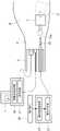
如图1以及图2所示,本实施方式所涉及的激光破碎系统1具备激光破碎装置3、硬性镜或者软性镜的尿管镜5、显示部7、图像信息提取部9、结石形态识别部11、波形设定部13以及波形信息存储部15。As shown in FIGS. 1 and 2 , the
激光破碎装置3具备激光光源21、光纤23、光纤连接部25、波形控制部(脉冲生成部、输出调整部)27。在图2中,标号29表示用户接口。The
作为激光光源21,例如能够使用铥光纤激光器(TLR-50/500-QCW-AC-Y16,IPGPhotonics)。取而代之,作为激光光源21,例如也可以使用Holmium:YAG激光、Thulium:YAG激光、Erbium:YAG激光、脉冲染料激光(Pulsed dye laser)或Q-switchedNd:YAG激光。As the
光纤23例如可以是单模光纤和多模光纤中的任一种,也可以是双包层构造的光纤。另外,光纤23也可以添加铥(Thulium)。光纤23通过尿管镜5的通道5a被引导到尿路P内。尿路P内填充有尿、水或生理盐水等溶液W。光纤23具备射出被导光的激光的光纤前端(激光射出端)23a。The
光纤连接部25读取所连接的光纤23的信息。并且,光纤连接部25将包含光纤23的芯径以及NA等特性的光纤识别信息传送到波形控制部27。The optical
尿管镜5观测尿路结石(结石)S的形态。如图2所示,例如,在尿管镜5上连接有产生照明光的照明光源17和生成将尿路结石S图像化的尿管镜图像的图像处理器(图像取得部)19。由图像处理器19生成的图像显示于显示部7。The
通过显示于显示部7的尿管镜图像,用户能够确认由激光生成的气泡B(参照图3)是否到达了尿路结石S。并且,用户通过观察尿管镜图像进行判断,由此能够通过波形设定部13设定激光的波形。The user can confirm whether or not the air bubbles B (see FIG. 3 ) generated by the laser have reached the urolithiasis S through the ureteroscope image displayed on the
图像信息提取部9基于由尿管镜5生成的尿管镜图像,提取尿路结石S的形态。The image
结石形态识别部11通过识别由图像信息提取部9提取出的尿路结石S的形态来生成波形控制信息,并将生成的波形控制信息传送到波形控制部27。The calculus
波形设定部13设定由用户选择的激光的波形。波形设定部13将表示所设定的波形的波形信息传送到波形控制部27。The
在波形信息存储部15中存储有激光光源21的波长信息和用于根据波长信息生成适当的波形的波形信息。The wavelength information of the
波形控制部27基于从光纤连接部25发送来的光纤识别信息、从波形设定部13发送来的波形信息、以及从结石形态识别部11发送来的波形控制信息中的至少1个,从波形信息存储部15取得期望的波形信息。而且,波形控制部27基于所取得的波形信息来控制激光光源21的激励。The
波形控制部27例如将激光的脉冲形状形成为上升三角脉冲。具体而言,如图3所示,波形控制部27首先使从激光光源21激励出的激光的输出单调增大。由此,通过从光纤前端23a射出的脉冲状的激光,从光纤前端23a连续地生成多个气泡B。并且,通过由多个气泡B结合而构成的气泡结合体BB,将光纤前端23a与尿路结石S之间连结。将使激光的输出单调增大的该期间设为第一期间。在第一期间中,也可以以比规定的梯度小的梯度使输出单调增大。The
接着,波形控制部27在第一期间后切换激光的输出,以比规定的梯度大的梯度使输出单调减小。由此,由于气泡结合体BB消失而产生吸引力。然后,通过吸引力将尿路结石S向光纤前端23a拉近。将使激光的输出单调减小的该期间设为第二期间。Next, the
激光的重复频率优选为1.7kHz以上且3.0kHz以下。激光的重复频率也可以为1.7kHz以上且2.5kHz以下。The repetition frequency of the laser light is preferably 1.7 kHz or more and 3.0 kHz or less. The repetition frequency of the laser light may be 1.7 kHz or more and 2.5 kHz or less.
另外,激光的重复频率也可以为2.5kHz以上且3.0kHz以下。另外,激光的输出的梯度也可以在0.625~5.0W/μs的范围内。例如,在激光的输出成为向右上升的波形的第一期间,以2.5W/μsec以下的梯度使输出缓慢地单调增大。另外,在成为接着该第一期间后面的向右下降的波形的第二期间,以2.5W/μsec以上的梯度使输出急剧地单调减小,优选停止输出。In addition, the repetition frequency of the laser light may be 2.5 kHz or more and 3.0 kHz or less. In addition, the gradient of the output of the laser light may be in the range of 0.625 to 5.0 W/μs. For example, in the first period in which the output of the laser light has a waveform rising to the right, the output is gradually and monotonically increased with a gradient of 2.5 W/μsec or less. In addition, in the second period, which becomes a waveform that falls to the right following the first period, the output is rapidly monotonically decreased with a gradient of 2.5 W/μsec or more, and the output is preferably stopped.
脉冲形状的生成例如能够使用函数发生器(WF1974,NF)。图像信息提取部9、结石形态识别部11以及波形控制部27的上述处理也可以由包括硬件的至少1个处理器来执行。For the generation of the pulse shape, for example, a function generator (WF1974, NF) can be used. The above-described processing of the image
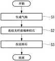
接着,本实施方式的激光破碎方法例如如图4的流程图所示,包括:步骤S1,通过从光纤前端23a射出脉冲状的激光,从光纤前端23a连续地生成多个气泡B;步骤S2,通过由多个气泡B结合而构成的气泡结合体BB,将光纤前端23a与尿路结石S之间连结;以及步骤S3,通过由于气泡结合体BB消失而产生的吸引力,将尿路结石S向光纤前端23a拉近。Next, as shown in the flow chart of FIG. 4 , the laser breaking method of this embodiment includes: step S1, by emitting pulsed laser light from the optical fiber
接着,对本实施方式所涉及的激光破碎系统1以及激光破碎方法的作用进行说明。Next, the operation of the
在通过本实施方式所涉及的激光破碎系统1以及激光破碎方法来破碎结石的情况下,在将光纤23连接于光纤连接部25之后,将光纤前端23a朝着溶液W中的尿路结石S配置。并且,维持从光纤前端23a到尿路结石S的距离处于规定的范围内的状态。从光纤连接部25向波形控制部27传送光纤识别信息。When a calculus is broken by the
接着,从照明光源17朝着尿路结石S照射照明光。另外,从激光光源21产生激光。激励出的激光经由光纤连接部25入射到光纤23。由光纤23引导的激光从光纤前端23a朝着尿路结石S射出。Next, illumination light is irradiated toward the urinary tract stone S from the
接着,由图像处理器19生成尿路结石S的图像,所生成的图像显示于显示部7。用户根据由显示部7显示的尿管镜图像,通过波形设定部13设定激光的波形。将表示所设定的波形的波形信息传送到波形控制部27。Next, an image of the urolithiasis S is generated by the
另外,通过图像信息提取部9,基于所生成的尿管镜图像来提取尿路结石S的形态。然后,通过结石形态识别部11,基于提取出的尿路结石S的形态来生成波形控制信息。将所生成的波形控制信息传送到波形控制部27。In addition, the image
通过波形控制部27,基于来自光纤连接部25的光纤识别信息、来自波形设定部13的波形信息、以及来自结石形态识别部11的波形控制信息中的至少1个,从波形信息存储部15取得所希望的波形信息,基于所取得的波形信息来控制激光光源21的激励。By the
具体而言,如图5所示,从激光光源21射出的激光的输出在输出以比规定的梯度小的梯度单调增大的第一期间和输出以比规定的梯度大的梯度单调减小的第二期间之间切换,并且按照第一期间、第二期间的顺序交替地重复。Specifically, as shown in FIG. 5 , the output of the laser light emitted from the
由此,例如,如图6所示,首先,在第一期间,射出输出以比规定的梯度小的梯度单调增大的激光,由此从光纤前端23a生成气泡B(图6的(a)的状态)。然后,当通过一边使输出单调增大一边射出激光而使气泡B成为某种程度的大小时,从气泡B的前端生成第二个气泡B(图6的(b)的状态)。Thus, for example, as shown in FIG. 6 , first, in the first period, the output of the laser light whose output is monotonically increased with a gradient smaller than a predetermined gradient is emitted, whereby the bubble B is generated from the
接着,当因气泡B被溶液W冷却而导致第一个气泡B收缩时,第二个气泡B残留(图6的(c)的状态)。进而,一边使输出单调增大一边射出激光,由此从光纤前端23a生成新的气泡B(图6的(d)的状态)。通过该新的气泡B的生长,当新的气泡B与第二个气泡B结合时,形成2个气泡B结合而成的气泡结合体BB(图6的(e)的状态)。Next, when the first bubble B shrinks due to the cooling of the bubble B by the solution W, the second bubble B remains (the state of FIG. 6( c )). Furthermore, by emitting laser light while increasing the output monotonically, new bubbles B are generated from the
当通过气泡结合体BB将光纤前端23a与尿路结石S之间连结时,激光透过气泡结合体BB而到达尿路结石S。由此,激光照射到尿路结石S。When the
接着,激光的输出从第一期间切换为第二期间。通过切换为第二期间,当激光的输出以比规定的梯度大的梯度单调减小时,气泡结合体BB消失(图6的(f)的状态)。由于气泡结合体BB的消失而产生吸引力,由此将尿路结石S拉近到光纤前端23a(图6的(g)的状态)。Next, the output of the laser light is switched from the first period to the second period. By switching to the second period, when the output of the laser light is monotonically decreased with a gradient larger than a predetermined gradient, the air-bubble complex BB disappears (the state in (f) of FIG. 6 ). An attractive force is generated by the disappearance of the air-bubble complex BB, whereby the urolithiasis S is pulled closer to the
接着,激光的输出从第二期间切换为第一期间。根据第一期间,当射出输出以比规定的梯度小的梯度单调增大的激光时(图6的(h)的状态),从光纤前端23a生成气泡B(图6的(i)的状态)。并且,当通过一边使输出单调增大一边射出激光而使从气泡B生成的第二个气泡B与尿路结石S接触时,激光透过气泡B,由此向尿路结石S照射激光(图6的(j)的状态)。Next, the output of the laser light is switched from the second period to the first period. According to the first period, when the output of the laser light monotonically increasing with a gradient smaller than a predetermined gradient is emitted (the state of (h) in FIG. 6 ), the bubble B is generated from the
接着,当第一个气泡B收缩时,第二个气泡B残留(图6的(k)的状态)。然后,反复进行与图6的(d)~(k)的状态相同的过程,直到将尿路结石S破碎成所希望的大小为止。通过伴随着所照射的激光的能量被尿路结石S中的水吸收而引起的温度上升的水蒸汽爆炸、或者尿路结石S本身对激光的能量的吸收所引起的热化学变化等,将尿路结石S破碎。Next, when the first bubble B shrinks, the second bubble B remains (the state of (k) of FIG. 6 ). Then, the same process as in the states of (d) to (k) of FIG. 6 is repeated until the urinary tract stone S is broken into a desired size. Urine is irradiated by water vapor explosion due to temperature rise caused by the energy of the irradiated laser light being absorbed by the water in the urolithiasis S, or thermochemical changes caused by the absorption of the laser energy by the urolithiasis S itself. The road stone S is broken.
如以上说明的那样,根据本实施方式所涉及的激光破碎装置3、激光破碎系统1以及激光破碎方法,能够高效地利用因气泡结合体BB的消失而产生的拉近作用。由此,能够防止因激光的冲击而导致尿路结石S向远离光纤前端23a的方向移动,能够在距光纤前端23a一定的距离内向尿路结石S照射激光。因此,能够有效地利用吸引效应,高效地向尿路结石S照射激光。As described above, according to the
在本实施方式中,如上所述,在激光的输出为向右上升的波形的第一期间,以2.5W/μsec以下的梯度使输出缓慢地单调增大,在为向右下降的波形的第二期间,以2.5W/μsec以上的梯度使输出急剧地单调减小,优选停止输出。In the present embodiment, as described above, in the first period in which the output of the laser light is a waveform rising to the right, the output is gradually increased monotonically with a gradient of 2.5 W/μsec or less, and in the first period when the output of the laser is a waveform falling rightward During the second period, the output is rapidly decreased monotonically with a gradient of 2.5 W/μsec or more, and the output is preferably stopped.
与此相对,作为本实施方式的比较例,在第一期间以超过2.5W/μsec的梯度使输出急剧地单调增大,在接下来的第二期间以低于2.5W/μsec的梯度使输出缓慢地单调减小的情况下,虽然根据介质(溶液W)的成分而多少有些不同,但是仅是未形成多个气泡B、或者产生多个未连结的离散的气泡B,几乎未确认到吸引效应。On the other hand, as a comparative example of the present embodiment, the output is rapidly monotonically increased with a gradient exceeding 2.5 W/μsec in the first period, and the output is increased with a gradient of less than 2.5 W/μsec in the next second period. In the case of a slow monotonous decrease, although there are some differences depending on the composition of the medium (solution W), only a large number of bubbles B are not formed, or a large number of discrete bubbles B that are not connected are generated, and suction is hardly confirmed. effect.
另外,在第一期间以超过2.5W/μsec的梯度使输出急剧地单调增大,之后,在使输出的梯度平稳(矩形脉冲所具有的水平或平坦的顶部也包含于此)的情况下,气泡B容易损坏。而且,多个气泡B不同时存在,或者气泡B彼此不连结而以各自的顺序消失。In addition, when the output is rapidly monotonically increased with a gradient exceeding 2.5 W/μsec in the first period, and thereafter, when the gradient of the output is stabilized (including the horizontal and flat top of the rectangular pulse), Bubbles B are easily damaged. Further, the plurality of bubbles B do not exist at the same time, or the bubbles B disappear in each order without being connected to each other.
另外,即使在第一期间以2.5W/μsec以下的梯度使输出缓慢地单调增大,在接下来的第二期间以2.5W/μsec以下的梯度使输出缓慢地单调减小的情况下,连结的气泡B也会断片式地消失或阶段性地消失,未发现充分的吸引效应。In addition, even if the output is gradually increased monotonically with a gradient of 2.5 W/μsec or less in the first period, and the output is slowly and monotonically decreased with a gradient of 2.5 W/μsec or less in the next second period, the connection The bubble B also disappears in pieces or in stages, and a sufficient attraction effect is not found.
从施加向右上升的波形的脉冲起到气泡B连结为止的时间根据介质以及波形以外的参数而不同。因此,若通过向虚设的或实际的尿路结石S照射具有与使用时同等的介质环境和参数的脉冲来进行测量,则能够取得从赋予向右上升的波形的脉冲起到气泡B连结为止的时间。The time from the application of the pulse of the waveform rising to the right until the connection of the bubbles B varies depending on the medium and parameters other than the waveform. Therefore, if the measurement is performed by irradiating a dummy or actual urinary tract stone S with a pulse having the same medium environment and parameters as in use, it is possible to obtain the pulse from the pulse with the waveform rising to the right until the connection of the bubble B. time.
本实施方式能够变形为以下的结构。The present embodiment can be modified into the following configurations.
在本实施方式中,采用了由第一期间和第二期间构成的上升三角脉冲。作为一个变形例,例如,如图7所示,波形控制部27也可以在第一期间之前,以比规定的梯度小的梯度使激光的输出单调减小。将在第一期间之前使激光的输出单调减小的该期间设为第三期间。In the present embodiment, a rising triangular pulse composed of a first period and a second period is used. As a modification, for example, as shown in FIG. 7 , the
并且,波形控制部27也可以在第三期间之前,以比规定的梯度大的梯度使激光的输出单调增大。将在第三期间之前使激光的输出单调增大的该期间设为第四期间。In addition, the
在该情况下,在第四期间,激光的输出以比规定的梯度大的梯度单调增大,由此从光纤前端23a迅速地生成第一个气泡B。接着,在第三期间,激光的输出以比规定的梯度小的梯度单调减小,由此在从第一个气泡B进一步生成第二个气泡B之后,两方的气泡B消失。In this case, in the fourth period, the output of the laser light monotonically increases with a gradient larger than a predetermined gradient, whereby the first bubble B is rapidly generated from the
脉冲波形具有将在本实施方式中说明的上升三角脉冲和使上升三角脉冲左右反转的下降三角脉冲以下降三角脉冲、上升三角脉冲的顺序连接而成的M字型。M字形状脉冲的左半部分、即下降三角脉冲由如下波形构成:相当于第四期间的、输出以2.5W/μsec以上的梯度单调增大的上升波形;和相当于接着的第三期间的、输出以1.25W/μsec以上2.5W/μsec以下的梯度单调减小的向右下降的波形。M字形状脉冲的右半部分与在本实施方式中说明的上升三角脉冲的波形相同。The pulse waveform has an M-shape in which the rising triangle pulse described in the present embodiment and the falling triangle pulse in which the rising triangle pulse is reversed left and right are connected in the order of the falling triangle pulse and the rising triangle pulse. The left half of the M-shaped pulse, that is, the falling triangular pulse is composed of the following waveforms: a rising waveform corresponding to the fourth period in which the output monotonically increases with a gradient of 2.5 W/μsec or more; and a subsequent third period corresponding to a rising waveform. , and output a waveform that decreases monotonically with a gradient of 1.25W/μsec or more and 2.5W/μsec or less. The right half of the M-shaped pulse has the same waveform as the rising triangle pulse described in this embodiment.
对上述结构的激光破碎系统1及激光破碎方法的作用进行说明。The operation of the
在通过本变形例所涉及的激光破碎系统1以及激光破碎方法来破碎结石的情况下,如图8所示,通过波形控制部27将激光的输出切换为第四期间、第三期间、第一期间以及第二期间,并且按照第四期间、第三期间、第一期间、第二期间的顺序重复进行。When the
由此,例如,如图9所示,首先,在第四期间,射出输出以比规定的梯度大的梯度单调增大的激光,由此从光纤前端23a迅速地生成气泡B(图9的(a)的状态)。Thus, for example, as shown in FIG. 9 , first, in the fourth period, the output of laser light whose output monotonically increases with a gradient larger than a predetermined gradient is emitted, whereby the bubble B is rapidly generated from the
接着,激光的输出从第四期间切换为第三期间。通过切换为第三期间,当射出输出以比规定的梯度小的梯度单调减小的激光时,气泡B逐渐变大,并且从气泡B的前端生成第二个气泡B(图9的(b)的状态)。并且,当两方的气泡B消失时,产生吸引力,由此将尿路结石S拉近到光纤前端23a(图9的(c)的状态)。Next, the output of the laser light is switched from the fourth period to the third period. By switching to the third period, when the output of the laser light whose output monotonically decreases with a gradient smaller than the predetermined gradient is emitted, the bubble B gradually increases in size, and the second bubble B is generated from the tip of the bubble B ( FIG. 9( b ) status). Then, when the air bubbles B on both sides disappear, an attractive force is generated, whereby the urolithiasis S is pulled closer to the
接着,激光的输出从第三期间切换为第一期间。通过切换为第一期间,当射出输出以比规定的梯度小的梯度单调增大的激光时,从光纤前端23a生成气泡B(图9的(d)的状态)。Next, the output of the laser light is switched from the third period to the first period. By switching to the first period, when the output of the laser beam monotonically increasing with a gradient smaller than a predetermined gradient is emitted, the bubble B is generated from the
在该情况下的第一期间中,通过在第四期间和第三期间中生成的气泡B,与激光保持光束而传播的光路对应的路径上的溶液W被升温,由此从光纤前端23a连续的多个气泡B生成为一块。然后,迅速地形成将光纤前端23a与尿路结石S连结的气泡结合体BB(图9的(e)的状态)。由此,激光透过气泡结合体BB,由此向尿路结石S照射激光。In the first period in this case, by the bubbles B generated in the fourth period and the third period, the temperature of the solution W on the path corresponding to the optical path in which the laser light is maintained and propagated is increased, thereby continuing from the
接着,激光的输出从第一期间切换为第二期间。通过切换为第二期间,当射出输出以比规定的梯度大的梯度单调减小的激光时,气泡结合体BB消失。由此,产生吸引力,从而将尿路结石S吸引向光纤前端23a(图9的(f)、(g)、(h)的状态)。Next, the output of the laser light is switched from the first period to the second period. By switching to the second period, when the output of the laser light whose output is monotonically decreased with a gradient larger than a predetermined gradient is emitted, the bubble complex BB disappears. Thereby, an attractive force is generated, and the urolithiasis S is attracted to the optical fiber
接着,激光的输出从第二期间切换为第四期间。通过切换为第四期间,当射出输出以比规定的梯度大的梯度单调增大的激光时,在光纤前端23a迅速地生成气泡B(图9的(i)的状态)。Next, the output of the laser light is switched from the second period to the fourth period. By switching to the fourth period, when the output of the laser light monotonically increasing with a gradient larger than a predetermined gradient is emitted, the bubble B is rapidly generated at the
接着,激光的输出从第四期间切换为第三期间。通过切换为第三期间,当射出输出以比规定的梯度小的梯度单调减小的激光时,气泡B逐渐变大,并且从气泡B的前端生成第二个气泡B(图9的(j)的状态)。然后,当两方的气泡B消失时,产生吸引力,由此将气泡B向光纤前端23a拉近(图的(k)的状态)。Next, the output of the laser light is switched from the fourth period to the third period. By switching to the third period, when the output of the laser light whose output monotonically decreases with a gradient smaller than a predetermined gradient is emitted, the bubble B gradually increases in size, and the second bubble B is generated from the tip of the bubble B ( FIG. 9( j ) status). Then, when the bubbles B on both sides disappear, an attractive force is generated, whereby the bubbles B are drawn toward the
接着,激光的输出从第三期间切换为第一期间。通过切换为第一期间,当射出输出以比规定的梯度小的梯度单调增大的激光时,从光纤前端23a生成气泡B(图9的(l)的状态)。Next, the output of the laser light is switched from the third period to the first period. By switching to the first period, when the output of the laser light monotonically increasing with a gradient smaller than a predetermined gradient is emitted, the bubble B is generated from the
在该情况下,通过在第四、第三期间生成的气泡B也使得激光的路径上的溶液W被升温,由此从光纤前端23a连续的多个气泡B生成为一块。然后,迅速地形成将光纤前端23a与尿路结石S连结的气泡结合体BB(图9的(m)的状态)。由此,激光透过气泡结合体BB,由此再次向尿路结石S照射激光。In this case, the temperature of the solution W on the path of the laser light is also increased by the bubbles B generated in the fourth and third periods, whereby a plurality of bubbles B continuous from the
当由于激光的冲击而使尿路结石S向远离光纤前端23a的方向移动时(图9的(n)、(o)、(p)的状态),重复进行与图9的(a)~(p)的状态相同的过程。并且,通过重复进行激光的照射,将尿路结石S破碎为所希望的大小。When the urolithiasis S is moved in a direction away from the
以上,根据本变形例,在第一、第二期间之前,通过第四期间迅速地生成气泡B,并且通过第三期间使激光的路径上的溶液W升温,由此在之后的第一期间,能够通过气泡结合体BB迅速地将光纤前端23a与尿路结石S之间连结。As described above, according to the present modification, the bubbles B are rapidly generated in the fourth period before the first and second periods, and the temperature of the solution W on the path of the laser light is increased in the third period, whereby in the subsequent first period, The
在本变形例中,M字形状脉冲的左半部分、即下降三角脉冲由如下的波形构成:相当于第四期间的、输出以5W/μsec以上的梯度单调增大的上升波形;和相当于接下来的第三期间的、输出以25W/μsec以上2.5W/μsec以下的梯度单调减小的向右下降的波形。In this modification, the left half of the M-shaped pulse, that is, the falling triangular pulse is composed of the following waveforms: a rising waveform whose output monotonically increases with a gradient of 5 W/μsec or more corresponding to the fourth period; and a waveform corresponding to the fourth period. In the next third period, a waveform that decreases monotonically with a gradient of not less than 25 W/μsec and not more than 2.5 W/μsec is output.
第四期间的上升波形是不存在形成气泡B的余地的陡峭的梯度。另外,在接着上升波形之后的向右下降的下降波形的第三期间,在从先前的陡峭的上升波形转变为下降时,生成比较大的尺寸的气泡B。并且,在第三期间,输出以平缓的梯度单调减小,由此维持气泡B直到下降波形的最后。因此,在第三期间,通过气泡B使介质升温。并且,在第三期间,输出以1.25W/μsec以上且2.5W/μsec以下的梯度单调减小,由此气泡B难以破裂,因此在不引起针对尿路结石S的后退作用的状态下维持气泡B。The rising waveform in the fourth period is a steep gradient in which there is no room for forming the bubble B. In addition, in the third period of the descending waveform that descends to the right next to the ascending waveform, when transitioning from the previous steep ascending waveform to descending, bubbles B of a relatively large size are generated. And, in the third period, the output decreases monotonically with a gentle gradient, thereby maintaining the bubble B until the end of the descending waveform. Therefore, in the third period, the temperature of the medium is raised by the bubbles B. In the third period, the output monotonically decreases with a gradient of 1.25 W/μsec or more and 2.5 W/μsec or less, so that the bubbles B are difficult to burst, so that the bubbles are maintained without causing the retreating effect on the urolithiasis S. B.
在通过从M字形状脉冲的左半部分的下降三角脉冲切换为右半部分的上升三角脉冲而转变为输出的上升时,在第四、第三期间的下降三角脉冲的过程中产生的气泡B暂时消失。但是,在接着在第一期间输出单调增大的过程中,在连续产生多个、典型的是2个或3个气泡B之后,这多个气泡B不消失而连结。之后,如上所述,通过从上升三角脉冲的上升转变为第二期间的急剧的下降,能够在短时间内得到吸引效应。When switching from the falling triangle pulse of the left half of the M-shaped pulse to the rising triangle pulse of the right half to change the output to the rising, the bubble B generated during the falling triangle pulse in the fourth and third periods disappeared temporarily. However, in the process of increasing the output monotonically in the first period next, after a plurality of, typically two or three, bubbles B are continuously generated, the plurality of bubbles B are connected without disappearing. After that, as described above, the attraction effect can be obtained in a short time by changing from the rising of the rising triangular pulse to the sharp falling of the second period.
与此相对,作为本变形例的比较例,在成为M字形状脉冲的左半部分的最初的上升波形的第四期间,在输出以小于2.5W/μsec的梯度单调增大的情况下,存在瞬间生成或大或小的1个以上的气泡B的情况,由此暗示了尿路结石S向远端远离的可能性。On the other hand, as a comparative example of the present modification, in the fourth period of the first rising waveform that becomes the left half of the M-shaped pulse, when the output monotonically increases with a gradient of less than 2.5 W/μsec, there is a The fact that one or more large or small bubbles B are instantaneously generated suggests the possibility that the urolithiasis S may move distally.
另外,在成为接着最初的上升波形之后的向右下降的下降波形的第三期间,在输出以超过2.5W/μsec的梯度急剧地单调减小的情况下,仅在下降波形的中途气泡B消失、或者产生多个未连结的离散的气泡B,通过气泡B对介质的升温不充分。In addition, in the third period that becomes a rightward descending descending waveform following the first ascending waveform, when the output rapidly monotonically decreases with a gradient exceeding 2.5 W/μsec, the bubble B disappears only in the middle of the descending waveform , or a plurality of unconnected discrete bubbles B are generated, and the heating of the medium by the bubbles B is insufficient.
另外,在第三期间,在采用接近平坦(矩形脉冲所具有的水平或平坦的顶部也包含于此)的梯度的情况下,气泡B容易损坏。而且,多个气泡B不同时存在,或者气泡B彼此不连结而以各自的顺序消失。In addition, in the third period, when a gradient close to flat (the horizontal or flat top of the rectangular pulse is also included) is used, the bubbles B are easily damaged. Further, the plurality of bubbles B do not exist at the same time, or the bubbles B disappear in each order without being connected to each other.
在本实施方式中,结石形态识别部11也可以作为基于图像来计算气泡B与尿路结石S之间的距离的计算部发挥功能。另外,与计算出的距离相关的信息也可以由显示部7显示。根据由显示部7显示的图像信息和由结石形态识别部11计算出的与距离相关的信息,用户能够容易地掌握光纤前端23a与尿路结石S之间的距离。In the present embodiment, the stone
另外,在本实施方式中,以具有间隔的方式反复射出激光,但也可以以不具有间隔的方式反复射出激光。In addition, in the present embodiment, the laser light is repeatedly emitted with intervals, but the laser light may be repeatedly emitted without intervals.
另外,在本实施方式中,示出了应用于尿管的例子,但也可以是从像胆管、肾脏那样在体内会产生结石的任意的脏器取得图像的内窥镜。优选一边观察图像一边实施与在各脏器中生成的结石的成分相应的激光碎石。关于使用内窥镜的激光破碎装置的方式,也可以参照题为碎石装置以及碎石系统的国际申请PCT/JP2019/007928。In addition, in this embodiment, an example of application to a urinary catheter is shown, but an endoscope that acquires an image from an arbitrary organ such as a bile duct and a kidney that generates calculi in the body may be used. It is preferable to perform laser lithotripsy according to the composition of the calculus generated in each organ while observing the image. With regard to the manner of the laser breaking device using the endoscope, reference may also be made to the international application PCT/JP2019/007928 entitled Lithotripsy Device and Lithotripsy System.
实施例Example
接着,对上述实施方式所涉及的激光破碎装置3、激光破碎系统1以及激光破碎方法的实施例进行说明。Next, examples of the
(方法)(method)
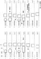
在本实施例中,将具有相同脉冲能量的4种脉冲形状、即矩形脉冲(Squre:Sq)、下降三角脉冲(Descending Triangle:DT)、上升三角脉冲(Ascending Triangle:AT)、M字形状脉冲(M-shaped Pulse:MP)作为比较对象。使用270um芯径的光纤(HLFDBX0270c、DornierMedTech)进行光能的传输。表1表示脉冲形状参数,图10表示各脉冲的脉冲形状。In this embodiment, four pulse shapes with the same pulse energy, namely, rectangular pulse (Squre: Sq), descending triangle pulse (Descending Triangle: DT), ascending triangle pulse (Ascending Triangle: AT), and M-shaped pulse are used. (M-shaped Pulse: MP) as a comparison object. Optical energy transmission was performed using a fiber with a core diameter of 270um (HLFDBX0270c, DornierMedTech). Table 1 shows the pulse shape parameters, and FIG. 10 shows the pulse shape of each pulse.
[表1][Table 1]
脉冲形状参数Pulse shape parameters

此外,作为图10所示的脉冲形状以外的参数的脉冲能量(J)、平均功率(W)、脉宽(μs)是在本实施例中选定的,能够称为优选的参数的一个例子。即,本实施例中采用的激光的脉冲均具有500W的平均功率和0.2J的脉冲能量,而它们的脉宽不同,与各自的脉冲形状相关。即,作为现有技术的矩形脉冲为400μs,下降三角脉冲以及上升三角脉冲均为800μs,M字形状脉冲为728μs。M字形状脉冲在相当于脉宽的一半的中央部的最下点处不为零而具有50W的平均功率。在这些脉冲形状中,能够利用平均功率和脉宽来规定与气泡的生成以及消失的动态相关联的脉冲输出的梯度。无论图10中明示的各参数的值如何,本发明都能够基于本说明书中叙述的发明的主旨而适当变更。In addition, the pulse energy (J), average power (W), and pulse width (μs), which are parameters other than the pulse shape shown in FIG. 10 , are selected in this embodiment, and can be referred to as examples of preferable parameters. . That is, the pulses of the lasers used in this embodiment all have an average power of 500 W and a pulse energy of 0.2 J, and their pulse widths are different, which are related to their respective pulse shapes. That is, the conventional rectangular pulse is 400 μs, the falling triangle pulse and the rising triangle pulse are both 800 μs, and the M-shaped pulse is 728 μs. The M-shaped pulse was not zero at the lowermost point of the central portion corresponding to half of the pulse width, but had an average power of 50 W. In these pulse shapes, the gradient of the pulse output associated with the dynamics of bubble generation and disappearance can be specified using the average power and pulse width. Regardless of the value of each parameter explicitly shown in FIG. 10 , the present invention can be appropriately changed based on the gist of the invention described in this specification.
如图11所示,由功率传感器(S322C、Thorlabs)43以及功率计(PM100D、Thorlabs)45测量从光纤(272μm-core MMF(HLFDBX0270C、Dornier))41照射的实际的平均功率。As shown in FIG. 11 , the actual average power irradiated from an optical fiber (272 μm-core MMF (HLFDBX0270C, Dornier)) 41 is measured by a power sensor (S322C, Thorlabs) 43 and a power meter (PM100D, Thorlabs) 45 .
另外,通过光检测器(DET10D/M、Thorlabs)47测量脉冲形状。在示波器49中进行16次数字平均而取得光检测器47的输出波形。通过将平均功率(W)除以脉冲速率(Hz)而算出脉冲能量(J)。在图11中,标号55表示光纤(Single Mode Fiber:单模光纤),标号57表示分色镜(DMLP1800L、Thorlabs R=0.0225(@λ=1.94μs)),标号59表示聚光透镜(LA5763-D、Thorlabs=50mm)。In addition, the pulse shape was measured by a photodetector (DET10D/M, Thorlabs) 47 . The output waveform of the
图12表示各脉冲的脉冲形状和脉冲能量。FIG. 12 shows the pulse shape and pulse energy of each pulse.
激光装置51使用铥光纤激光器(Thulium Fiber Laser)(TLR-50/500-QCW-AC-Y16、IPG Photonics)。由函数发生器(WF1974、NF)53进行脉冲形状的生成。The
(气泡观察)(Bubble observation)
如图13所示,使用高速数码相机(Fastcam SA-Z、Photoron)63,拍摄并记录各脉冲的气泡形成过程。拍摄速度设为10万帧/秒。As shown in FIG. 13 , a high-speed digital camera (Fastcam SA-Z, Photoron) 63 was used to photograph and record the bubble formation process of each pulse. The shooting speed was set to 100,000 frames/sec.
图13表示气泡形状解析系统61的设置。FIG. 13 shows the arrangement of the bubble
从设置有光纤65的丙烯酸壳体67的背面,通过以卤素灯为光源69的柯拉照明对摄影区域进行照明。气泡表现为照相机拍摄图像的阴影。标号67a表示灌流入口,标号67b表示灌流出口。From the back surface of the
如图14所示,将气泡长度(L)定义为从光纤端65a连续的气泡B的最大长度,将气泡宽度(W)定义为与光纤65垂直的方向的气泡宽度的最大值。As shown in FIG. 14 , the bubble length (L) is defined as the maximum length of the bubble B continuous from the
图15表示各脉冲的气泡形成过程。Figure 15 shows the bubble formation process for each pulse.
在矩形脉冲的情况下,从光纤端65a连续地生成2个气泡B并消失。2个气泡长度为相同程度。在下降三角脉冲的情况下,从光纤端65a连续地生成3个气泡B并消失。3个气泡长度逐渐变短。In the case of a rectangular pulse, two bubbles B are continuously generated and disappeared from the
上升三角脉冲使得从光纤端65a连续地生成3个气泡B并消失,3个气泡长度逐渐变长。M字形状脉冲使得从光纤端65a连续地生成3个气泡B并消失。第一个气泡B和第三个气泡B的长度为相同程度,第二个气泡B的长度比第一个和第三个气泡B短。The rising triangular pulse causes three bubbles B to be continuously generated from the
在图16中示出在各脉冲形状中连续生成和消失的多个气泡B各自的宽度、长度以及宽度与长度的比率。16 shows the respective widths, lengths, and ratios of widths and lengths of the plurality of bubbles B that are continuously generated and disappeared in each pulse shape.
各脉冲形状的多个气泡宽度的大小的顺序根据脉冲形状而不同。任意的脉冲形状的气泡B均表示沿着光纤65的长轴方向较长的椭圆型,但上升三角脉冲的第三个气泡B的形状接近球形。The order of the magnitudes of the plurality of bubble widths for each pulse shape differs depending on the pulse shape. The bubbles B of any pulse shape are elliptical long along the long axis direction of the
(吸引效应及结石后退)(attraction effect and stone regression)
图17A以及图17B示出评价光纤的前方方向的吸引效应的实验系统。17A and 17B show an experimental system for evaluating the attraction effect in the forward direction of the optical fiber.
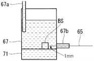
在聚苯乙烯(PS)单元71上配置2mm见方的结石模型(Bego Stone plus、混合比5:1、Bego Canada)BS。将光纤65在水平方向上设置在距PS单元71的上表面为1mm的高度。A 2 mm square stone model (Bego Stone plus, mixing ratio 5:1, Bego Canada) BS was placed on the polystyrene (PS)
通过摄像机(ARTCAM-130MI-BW、ARTRAY)73从侧方拍摄光纤65和结石模型BS。为了评价结石模型BS的移动的大小,在结石模型BS的上方设置数码相机75,取得激光照射前后的结石模型BS的位置(X、Y)。标号77表示氙灯。The
如图18所示,结石后退距离是将从激光照射结束后的光纤65的前端到结石模型BS的重心的距离(d)减去作为偏移的结石模型BS的半值宽度(d0)而得到的数值(d’)。As shown in FIG. 18 , the stone retreat distance is obtained by subtracting the half-value width (d0) of the stone model BS, which is an offset, from the distance (d) from the tip of the
进行如下的照射:将光纤65的前端与结石模型BS之间的距离设为0mm、0.5mm的情况下的针对2mm见方的结石模型BS的各脉冲形状的照射;和将该距离设为0mm的情况下的针对5mm见方的结石模型BS的各脉冲形状的照射。在各个条件中设为N=3。N表示各实验的试行次数。The following irradiations are performed: irradiation of each pulse shape for a 2 mm square calculus model BS when the distance between the tip of the
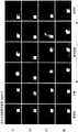
图19表示对设光纤65的前端与2mm见方的结石模型BS之间的距离为0.5mm的情况下的各脉冲形状下的结石模型BS的动态进行解析的结果的一例。FIG. 19 shows an example of results of analyzing the dynamics of the stone model BS in each pulse shape when the distance between the tip of the
在矩形脉冲和下降三角脉冲中,在激光照射刚开始后,结石模型BS向一个方向滑动后停止。在上升三角脉冲以及M字形状脉冲中,观察到在激光照射中结石模型BS有1次从光纤65的前端离开后接近、或在该处旋转的现象(吸引效应)。In the rectangular pulse and the falling triangle pulse, immediately after the laser irradiation starts, the stone model BS slides in one direction and stops. In the ascending triangle pulse and the M-shaped pulse, a phenomenon (attraction effect) in which the calculus model BS was separated from the tip of the
在上升三角脉冲中,在激光照射即将结束之前被拉近向光纤65的前端的结石模型BS描绘较大的弧形而被吹飞。其结果,激光照射结束后的结石模型BS的位置与矩形脉冲和上升三角脉冲的情况相比不怎么变化。在M字形状脉冲的情况下,激光照射结束后的结石模型BS的位置与其他例子相比更接近光纤65的前端。In the ascending triangle pulse, the stone model BS drawn toward the tip of the
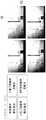
图20表示将光纤65的前端与结石模型BS之间的距离设为0mm的情况下的5mm见方的结石模型BS的结果的一例。FIG. 20 shows an example of the result of the calculus model BS of 5 mm square when the distance between the distal end of the
在矩形脉冲中,虽然对于结石模型BS而言吸引效应较弱地发挥作用,但结石模型BS大幅滑动。在下降三角脉冲中,结石模型BS在激光照射后向一个方向滑动后停止。上升三角脉冲和M字形状脉冲在激光照射中显示出吸引效应现象,在激光照射结束后,结石模型BS在靠近光纤65的前端的位置停止。In the rectangular pulse, although the attraction effect is weak for the stone model BS, the stone model BS slides greatly. In the descending triangle pulse, the stone model BS stopped after sliding in one direction after laser irradiation. The rising triangle pulse and the M-shaped pulse show an attraction effect phenomenon in the laser irradiation, and the stone model BS stops at a position close to the tip of the
对于上述的动画解析的结果,将确认到吸引效应现象的情况设为吸引成功,将未确认到吸引效应现象的情况设为吸引失败,将各条件下的N=3的试行中的吸引成功的数量作为吸引成功率汇总于表2。As a result of the above-mentioned animation analysis, the case where the attraction effect phenomenon was confirmed was regarded as successful attraction, the case where the phenomenon of attraction effect was not confirmed was regarded as the attraction failure, and the case where the attraction effect was successful in the trial run with N=3 under each condition was regarded as successful attraction. The numbers are summarized in Table 2 as attraction success rates.
[表2][Table 2]
吸引成功率Attraction success rate

在上升三角脉冲和M字形状脉冲中,2mm见方的结石模型BS(光纤-结石模型间距离:0.5mm)和5mm见方的结石模型BS的情况下的吸引成功率高。但是,在2mm见方的结石模型BS(光纤-结石模型间距离:0mm)的情况下,吸引成功率低。In the ascending triangle pulse and the M-shaped pulse, the suction success rate was high in the case of the 2 mm square stone model BS (fiber-stone model distance: 0.5 mm) and the 5 mm square stone model BS. However, in the case of a 2 mm square stone model BS (distance between optical fiber and stone model: 0 mm), the suction success rate was low.
结石后退距离的测量结果如表3所示。The measurement results of the stone retreat distance are shown in Table 3.
[表3][table 3]
结石后退stone back

M字形状脉冲在任意的条件下与其他脉冲形状相比结石后退距离都小。上升三角脉冲在5mm见方的结石模型BS的条件下结石后退距离小,在其他条件下与其他脉冲形状为相同程度。Compared with other pulse shapes, the M-shaped pulse has a smaller receding distance of the stone under any conditions. Under the condition of 5mm square stone model BS, the ascending triangle pulse has a small stone retreat distance, and it is the same degree as other pulse shapes under other conditions.
如图21所示,为了评价光纤65与结石模型BS之间的距离与吸引成功率的关系,在光纤65的前端与结石模型BS之间的距离为0mm、0.5mm、1mm、2mm的距离的条件下,设N=3对结石模型BS的动态进行动画解析。该实验的脉冲形状使用上升三角脉冲。其结果,在距离为0.5mm、1mm的条件下,吸引成功率高。这样,确认了存在吸引成功率变高的间隔距离。As shown in FIG. 21 , in order to evaluate the relationship between the distance between the
根据图20、图21的研究结果可知,根据作为对象的结石与激光射出端之间的距离、结石的大小那样的条件,有时吸引成功率不同,因此优选在掌握这些条件的同时执行碎石。作为用于此的图像取得单元,优选具有能够对从光纤65的前端(激光射出端)到结石模型BS的距离为0.5mm、1mm、2mm的范围进行图像化的焦距。20 and 21 , the suction success rate may vary depending on conditions such as the distance between the target calculus and the laser emitting end and the size of the calculus. Therefore, it is preferable to perform lithotripsy while grasping these conditions. The image acquisition means for this preferably has a focal length capable of imaging the distances from the tip (laser exit end) of the
使用高速数码相机(Fastcam SA-Z、Photoron)63,以5万帧/秒的拍摄速度,如图22所示,观察气泡B,测量光纤65与结石模型BS的相互作用。其结果可知,在吸引效应成功的例子中,在小于等于气泡B的最大长度的情况下,气泡B吸入捕获结石模型BS。Using a high-speed digital camera (Fastcam SA-Z, Photoron) 63 at a shooting speed of 50,000 frames per second, as shown in FIG. 22 , the bubble B was observed, and the interaction between the
(吸引效应的详细机理)(Detailed mechanism of attraction effect)
在与气泡B相互作用的结石S的动态中,如图23所示,如下的4个力的关系是重要的,这4个力为:伴随气泡B的收缩的瞬间的拉近力、气泡B破裂后产生的喷射水流、照射的激光穿过气泡B之间而碰到结石S使得结石S破碎时产生的反作用力、作用于结石S的与地面的静摩擦力。In the dynamics of the stone S interacting with the bubble B, as shown in FIG. 23 , the relationship between the following four forces is important. The jet water flow generated after the rupture, the irradiated laser pass between the bubbles B and hit the stone S, the reaction force generated when the stone S is broken, and the static friction force acting on the stone S and the ground.
所照射的激光的光能被水吸收而产生气泡B。然后,当膨胀的气泡B与结石S接触时,通过气泡B到达结石S的光能使结石S破碎。当膨胀的气泡B转变为收缩时,由于气泡B的内外的压力差,吸引力在气泡B的收缩方向上发挥作用。由于气泡B因收缩而破碎的反作用,在推压结石S的方向上产生水流。The light energy of the irradiated laser light is absorbed by water, and bubbles B are generated. Then, when the expanded bubble B is in contact with the stone S, the light reaching the stone S through the bubble B can break the stone S. When the expanded bubble B turns into contraction, the attractive force acts in the contraction direction of the bubble B due to the pressure difference between the inside and outside of the bubble B. Due to the reaction of the collapse of the bubbles B due to the contraction, a water flow is generated in the direction in which the stone S is pushed.
假设在破碎反作用力和水流的力超过吸引力和作用于结石S的静摩擦力的情况下,结石S向后方移动。此时,在气泡B到达结石S之后,通过迅速地减少照射能量来降低破碎反作用力。在伴随气泡B的收缩的吸引力超过作用于结石S的静摩擦力或者结石S的惯性力,气泡破裂后的水流也低于结石S的惯性力的情况下,产生吸引效应。It is assumed that the stone S moves backward under the condition that the crushing reaction force and the force of the water flow exceed the attractive force and the static friction force acting on the stone S. At this time, after the bubble B reaches the stone S, the crushing reaction force is reduced by rapidly reducing the irradiation energy. When the attraction force accompanying the contraction of the bubble B exceeds the static friction force or the inertial force acting on the stone S, and the water flow after the bubble burst is also lower than the inertial force of the stone S, the attraction effect occurs.
(与以往的波纹形状的对比)(Comparison with the conventional corrugated shape)
以往的脉冲形状如矩形状或阶梯状脉冲那样,脉冲输出的峰值持续,或者为了专门得到破碎效果而使气泡生成期间短,因此多个气泡不连结。在发明人的进一步的研究中,预想到即使在使用专利文献2所公开的那样的第一脉冲和第二脉冲的情况下,即使在光纤前端生成的气泡因间隔而到达结石,之后气泡也被分割为光纤侧和结石侧,附着于结石侧的残留的气泡在任意的时机消失,从而发生后退。这样,以往的基于脉冲形状的碎石的概念优先向结石S的消融注入大量的能量,因此认为即使具有产生吸引效应的条件,也会由于发生超过该吸引效应的后退而将结石S向后方吹飞。特别是,通过发明人的研究可知,对于矩形状的脉冲、仅产生破碎效果那样的输出足够高的脉冲而言,产生的气泡B过小,或者气泡的形状不沿着激光的照射方向连结成长条状,因此即使产生吸引力,后退力也会超过吸引力,因此难以发挥吸引效应。In the conventional pulse shape, such as a rectangular or stepped pulse, the peak value of the pulse output is continued, or the bubble generation period is short in order to obtain the crushing effect exclusively, so that a plurality of bubbles are not connected. In the further study of the inventors, it is expected that even when the first pulse and the second pulse as disclosed in
上升三角以及M字形状脉冲具有在适当的距离的条件下吸引结石S的效果。并且,M字形状脉冲的情况下结石的后退小。The ascending triangle and the M-shaped pulse have the effect of attracting the stone S under the condition of an appropriate distance. In addition, in the case of the M-shaped pulse, the regression of the stone is small.
(方法:光纤侧方的吸引效应)(Method: Attractive effect on the side of the fiber)
如图24所示,在丙烯酸壳体67内铺设PS单元71,在PS单元71上配置2mm见方的结石模型(Begostone)BS。将生理盐水从灌流入口67a以约20ml/min的速度注入,将该生理盐水从灌流出口67b排出。使用高速数码相机(Fastcam SA-Z、Photoron)63拍摄结石模型BS的移动,用氙光源77进行照明。在丙烯酸壳体67内,将200μm芯径的光纤65相对于PS单元71的上表面垂直地配置。As shown in FIG. 24 , a
如图25所示,将光纤65与结石模型BS之间的距离调整为X,将从PS单元71的上表面到光纤65的前端的距离调整为Z。As shown in FIG. 25 , the distance between the
(结果:光纤侧方的吸引效应)(Result: Attractive effect on the side of the fiber)
图26表示Z=2.5mm、X=1.5mm的配置条件下的矩形脉冲、下降三角脉冲、上升三角脉冲以及M字形状脉冲的吸引效应的评价结果。将脉冲能量为0.2J、脉冲频率为80Hz、激光照射时间为1秒作为激光的照射条件。FIG. 26 shows the evaluation results of the attraction effect of the rectangular pulse, the falling triangle pulse, the rising triangle pulse, and the M-shaped pulse under the arrangement conditions of Z=2.5 mm and X=1.5 mm. The pulse energy was 0.2 J, the pulse frequency was 80 Hz, and the laser irradiation time was 1 second as the laser irradiation conditions.
其中,在矩形脉冲和上升三角脉冲中,结石模型BS被朝向光纤65下方拉近,由此激光照射到结石模型BS,其结果,粉尘上升。将其定义为吸引成功,通过解析各取得动画数据来判定是否吸引成功。Among them, in the rectangular pulse and the ascending triangular pulse, the calculus model BS is drawn downward toward the
将吸引速度(Velocity)作为吸引成功的情况下的光纤65与结石模型BS之间的距离(X)与从激光照射开始(laser start)到激光最初射中(stone hit)结石模型BS为止的时间、即激光最早到达结石模型BS为止的时间之比而计算出。Let the suction velocity (Velocity) be the distance (X) between the
Velocity(mm/sec)=X/(t[stone hit]-t[laser start])Velocity(mm/sec)=X/(t[stone hit]-t[laser start])
图27表示吸引成功率和吸引速度的结果。在矩形脉冲和上升三角脉冲的情况下光纤侧方的吸引效应表现得较多。吸引速度随着距离的增大而降低。矩形脉冲的吸引力比上升三角脉冲的吸引力强。FIG. 27 shows the results of the suction success rate and the suction speed. In the case of rectangular pulses and rising triangular pulses, the attraction effect on the side of the fiber is more pronounced. The speed of attraction decreases with distance. The attraction of rectangular pulses is stronger than that of rising triangle pulses.
光纤侧方的吸引效应对于加快爆米花碎石的开始、或将周围的位于附近的1个以上的结石S向光纤前方拉近是有用的。根据本实验结果,在矩形脉冲和上升三角脉冲的情况下出现光纤侧方的吸引效应,矩形脉冲的侧方的吸引力比上升三角脉冲的侧方的吸引力高。The attraction effect on the side of the optical fiber is useful for speeding up the initiation of popcorn crushing, or for pulling one or more nearby stones S closer to the front of the optical fiber. According to the experimental results, the attraction effect on the side of the fiber appears in the case of the rectangular pulse and the rising triangular pulse, and the attractive force on the side of the rectangular pulse is higher than that of the rising triangular pulse.
但是,由于矩形脉冲向光纤前方的能量送达率比上升三角脉冲高,所以在临床中,被水吸收的能量的剩余能量被输送至光纤前方所朝向的生物体粘膜,所以必须慎重地进行,以使生物体粘膜的温度不会比正常的状态高。在这一点上,可以认为阶梯状的脉冲也同样应该慎重地处理。与此相对,上升三角脉冲的峰值的脉冲只不过是一瞬间,因此向光纤前方送达的能量少,另一方面,能够得到光纤侧方的吸引效应,因此能够在降低对生物体粘膜的损伤风险的同时,将光纤侧方的结石S吸引向光纤65。在这一点上,认为M字形状脉冲也同样对生物体的损伤少,因此优选如后述的变形例那样,以使M字形状脉冲的形状接近上升三角的形状的方式,变更构成脉冲的每个期间的输出的梯度。这样,在侧方的吸引效应中,在生物体中利用的激光碎石中,认为本发明的脉冲形状比矩形脉冲更适合。However, since the energy delivery rate of the rectangular pulse to the front of the optical fiber is higher than that of the ascending triangle pulse, in clinical practice, the remaining energy of the energy absorbed by the water is transferred to the living mucosa where the front of the optical fiber is directed, so it must be carried out carefully. So that the temperature of the living body mucous membrane is not higher than the normal state. At this point, it can be argued that stepped pulses should also be handled with care. On the other hand, since the peak of the rising triangular pulse is only a momentary pulse, less energy is sent to the front of the optical fiber. On the other hand, the suction effect on the side of the optical fiber can be obtained, so the damage to the living mucous membrane can be reduced. At the same time of risk, the stone S on the side of the optical fiber is attracted to the
(脉冲形状的变形例)(Variation of pulse shape)
脉冲形状即使是图28的(a)~(f)所示的脉冲形状也显示同样的效果。图28的(a)表示上升三角脉冲的变形例,图28的(b)~(f)表示M字形状脉冲的变形例。这些变形例均具有上述那样的脉冲波形的梯度。根据图28的(a)所示的脉冲形状,作为上升三角形状的脉冲的变形例,单调增大的第一期间和单调减小的第二期间也可以是大致相同的规定梯度。另外,根据图28的(b)~(d)所示的脉冲形状,作为M字形状脉冲的变形例,也可以任意地变更第一组与第二组的相对梯度的大小关系,其中该第一组是与脉冲输出单调增大的脉冲相关的、相当于第一期间和第四期间的脉冲,该第二组是与脉冲输出单调减小的脉冲相关的、相当于第二期间和第三期间的脉冲。另外,在本发明的实施例中,在单调增大的第一期间和单调减小的第二期间,脉冲输出从增大转变为减小的部分的形状成为折线,由此提高气泡的消失作用,但在未预定气泡的消失的其他部分,不需要为折线的形状。因此,例如也可以如图28的(e)所示的脉冲形状那样,将从相当于M字形状脉冲的中央部的第三期间到第一期间,脉冲的输出从减小转为增大的部分变更为具有拐点的曲线。进而,根据本发明的实施例,如图10所示,通过使M字形状脉冲的上述中央部的脉冲输出大于零,能够对在第三期间内被升温的溶液W迅速地进行下一个气泡生成。因此,如图28的(e)及(f)所示,也可以是形成曲线或矩形状的波谷的脉冲形状。进而,根据图28的(f),仅限于M字形状脉冲的变形例,能够将2个峰值的部分分别变更为宽度狭小的矩形状。即,如图所示,在M字形状脉冲的中央部被充分升温的液体中所连结的气泡有可能难以通过至多不到整体的30%的宽度的矩形脉冲来解除连结。The same effect is exhibited even when the pulse shape is the pulse shape shown in (a) to (f) of FIG. 28 . (a) of FIG. 28 shows a modification of the rising triangular pulse, and (b) to (f) of FIG. 28 show a modification of the M-shaped pulse. All of these modifications have the gradient of the pulse waveform as described above. According to the pulse shape shown in FIG. 28( a ), as a modification of the ascending triangle-shaped pulse, the first period that monotonically increases and the second period that monotonically decreases may have substantially the same predetermined gradient. In addition, according to the pulse shapes shown in (b) to (d) of FIG. 28 , as a modification of the M-shaped pulse, the magnitude relationship between the relative gradients of the first group and the second group may be arbitrarily changed, wherein the first group One group is the pulses corresponding to the first period and the fourth period related to the pulses whose pulse output is monotonically increasing, and the second group is the pulses whose pulse output is monotonically decreasing, corresponding to the second period and the third period period pulse. In addition, in the embodiment of the present invention, in the first period that monotonically increases and the second period that monotonically decreases, the shape of the portion where the pulse output changes from increasing to decreasing becomes a polygonal line, thereby enhancing the bubble disappearing effect , but in other parts where the disappearance of the bubble is not predetermined, it does not need to be in the shape of a polyline. Therefore, for example, as in the pulse shape shown in (e) of FIG. 28 , from the third period to the first period corresponding to the central part of the M-shaped pulse, the output of the pulse may be changed from decreasing to increasing. Parts are changed to curves with inflection points. Furthermore, according to the embodiment of the present invention, as shown in FIG. 10 , by making the pulse output of the central portion of the M-shaped pulse larger than zero, the next bubble generation can be rapidly performed for the solution W heated in the third period. . Therefore, as shown in (e) and (f) of FIG. 28 , a pulse shape that forms a curved or rectangular trough may be used. Furthermore, according to (f) of FIG. 28 , only in the modification of the M-shaped pulse, it is possible to change the portions of the two peaks into a rectangular shape with a narrow width, respectively. That is, as shown in the figure, there is a possibility that the bubbles connected in the liquid heated sufficiently at the center of the M-shaped pulse may be difficult to be disconnected by the rectangular pulse having a width of at most less than 30% of the whole.
如上所述,根据本实施例,通过调整激光的脉冲形状,将液体中生成的气泡B的收缩来拉近结石S的力有效化。由此,通过减小因碎石而产生的反作用力,来减少结石后退,或者使对生物体粘膜的损伤最小化。特别是,通过将1个以上的结石S向激光的照射区域拉近,能够减轻用户通过使激光照射装置移动而针对每个结石S准确地对准的麻烦,有助于利用短时间进行治疗。As described above, according to the present embodiment, by adjusting the pulse shape of the laser light, the force of the contraction of the air bubbles B generated in the liquid to draw the stone S closer is made effective. Thereby, by reducing the reaction force generated by the crushing of the stone, the regression of the stone can be reduced, or the damage to the mucosa of the living body can be minimized. In particular, by drawing one or more calculi S closer to the laser irradiation area, the user can reduce the trouble of accurately aligning each calculus S by moving the laser irradiating device, thereby contributing to treatment in a short time.
另外,通过向2个以上的结石S的中间照射激光,在这些结石S集中于激光的照射区域之后,各结石S能够被同时破碎。在同时破碎多个结石S的情况下,也能够减少体内的温度上升。并且,被拉近到激光照射区域的1个以上的结石S能够在直到被破碎到能够从体内自然地排出的大小为止的期间停留在照射区域。In addition, by irradiating the middle of two or more stones S with laser light, after these stones S are concentrated in the irradiation area of the laser light, each stone S can be broken at the same time. Even when a plurality of calculi S are broken at the same time, the temperature rise in the body can be reduced. In addition, the one or more stones S that have been brought close to the laser irradiation area can stay in the irradiation area until they are crushed to a size that can be naturally excreted from the body.
以上,参照附图对本发明的实施方式进行了详述,但具体的结构不限于该实施方式,也包含不脱离本发明的主旨的范围的设计变更等。例如,并不限定于将本发明应用于上述实施方式以及变形例,也可以应用于将这些实施方式以及变形例适当组合的实施方式,并不特别限定。As mentioned above, although embodiment of this invention was described in detail with reference to drawings, a specific structure is not limited to this embodiment, Design change etc. are included in the range which does not deviate from the summary of this invention. For example, the present invention is not limited to the above-described embodiments and modifications, and can be applied to embodiments in which these embodiments and modifications are appropriately combined, and is not particularly limited.
标号说明Label description
1 激光破碎系统1 Laser crushing system
3 激光破碎装置3 Laser crushing device
7 显示部7 Display
11 结石形态识别部(计算部)11 Stone Shape Recognition Department (Calculation Department)
19 图像处理处理器(图像取得部)19 Image processing processor (image acquisition part)
23 光纤23 Fiber
23a 光纤前端23a Fiber Front End
27 波形控制部(脉冲生成部、输出调整部)27 Waveform control part (pulse generation part, output adjustment part)
S 尿路结石(结石)S Urinary tract stones (stones)
Claims (19)
Applications Claiming Priority (3)
| Application Number | Priority Date | Filing Date | Title |
|---|---|---|---|
| US201962934019P | 2019-11-12 | 2019-11-12 | |
| US62/934,019 | 2019-11-12 | ||
| PCT/JP2020/020408WO2021095291A1 (en) | 2019-11-12 | 2020-05-22 | Laser spallation device, laser spallation system, and laser spallation method |
Publications (2)
| Publication Number | Publication Date |
|---|---|
| CN114599300Atrue CN114599300A (en) | 2022-06-07 |
| CN114599300B CN114599300B (en) | 2024-06-25 |
Family
ID=75912110
Family Applications (2)
| Application Number | Title | Priority Date | Filing Date |
|---|---|---|---|
| CN202080074521.5AActiveCN114599300B (en) | 2019-11-12 | 2020-05-22 | Output adjustment device for laser crushing device, laser crushing system, and attraction force generation method |
| CN202080074514.5APendingCN114630635A (en) | 2019-11-12 | 2020-05-22 | Laser crushing device, laser crushing system and laser crushing method |
Family Applications After (1)
| Application Number | Title | Priority Date | Filing Date |
|---|---|---|---|
| CN202080074514.5APendingCN114630635A (en) | 2019-11-12 | 2020-05-22 | Laser crushing device, laser crushing system and laser crushing method |
Country Status (4)
| Country | Link |
|---|---|
| US (3) | US12365048B2 (en) |
| JP (1) | JP7360471B2 (en) |
| CN (2) | CN114599300B (en) |
| WO (2) | WO2021095291A1 (en) |
Families Citing this family (7)
| Publication number | Priority date | Publication date | Assignee | Title |
|---|---|---|---|---|
| AU2021388028B2 (en)* | 2020-11-25 | 2025-02-13 | Lumenis Ltd | Method and system for estimating distance between a fiber end and a target |
| US12329396B2 (en) | 2022-03-02 | 2025-06-17 | Calyxo, Inc. | Kidney stone treatment system |
| US20240108412A1 (en) | 2022-09-29 | 2024-04-04 | Calyxo, Inc. | Tool guiding device for kidney stone treatment apparatus |
| WO2024155906A1 (en)* | 2023-01-20 | 2024-07-25 | Ipg Photonics Corporation | Laser emission modulation for treatment of calculi |
| CN116251136B (en)* | 2023-03-20 | 2024-03-15 | 吉首大学 | A method for extracting total active ingredients from male flowers of Eucommia ulmoides |
| WO2024201976A1 (en)* | 2023-03-31 | 2024-10-03 | オリンパス株式会社 | Optical fiber holder, optical treatment device, and optical treatment system |
| WO2025115206A1 (en)* | 2023-12-01 | 2025-06-05 | オリンパス株式会社 | Laser light irradiation system, laser control device, and laser light irradiation method |
Citations (17)
| Publication number | Priority date | Publication date | Assignee | Title |
|---|---|---|---|---|
| US5860972A (en)* | 1995-10-26 | 1999-01-19 | Xintec Corporation | Method of detection and destruction of urinary calculi and similar structures |
| WO2000048525A2 (en)* | 1999-02-19 | 2000-08-24 | Scimed Life Systems, Inc. | Laser lithotripsy device with suction |
| CN1290353A (en)* | 1997-10-06 | 2001-04-04 | 阿克丘拉斯有限公司 | Methods and apparatus for ablating tissue |
| WO2006128038A2 (en)* | 2005-05-26 | 2006-11-30 | Ntk Enterprises, Inc. | Device, system, and method for epithelium protection during cornea reshaping |
| JP2007097865A (en)* | 2005-10-05 | 2007-04-19 | Matsushita Electric Ind Co Ltd | Laser equipment |
| CN101273915A (en)* | 2008-04-30 | 2008-10-01 | 爱科凯能科技(北京)有限公司 | Laser lithotripsy device |
| JP2009213589A (en)* | 2008-03-09 | 2009-09-24 | Kunio Awazu | Apparatus for diagnosing and crushing calculus and method for diagnosing and crushing calculus using infrared tunable laser |
| US20100137847A1 (en)* | 2008-12-02 | 2010-06-03 | Ceramoptec Industries Inc. | Method and device for laser lithotripsy |
| JP2013031701A (en)* | 2006-07-13 | 2013-02-14 | Reliant Technologies Llc | Apparatus for adjustable fractional optical dermatological treatment |
| CN103547241A (en)* | 2011-05-18 | 2014-01-29 | 爱尔康手术激光股份有限公司 | Imaging-controlled laser surgical system |
| US20140276101A1 (en)* | 2013-03-14 | 2014-09-18 | Boston Scientific Scimed, Inc. | Medical device for detecting a target and related methods of use |
| EP2939631A1 (en)* | 2014-04-30 | 2015-11-04 | Cook Medical Technologies LLC | Laser apparatus for calculi removal |
| US20150342678A1 (en)* | 2014-05-28 | 2015-12-03 | Institut National D'optique | Laser-directed microcavitation |
| CN105682535A (en)* | 2013-11-11 | 2016-06-15 | 捷锐士阿希迈公司(以奥林巴斯美国外科技术名义) | Aiming beam detection for safe laser lithotripsy |
| CN106455941A (en)* | 2014-05-04 | 2017-02-22 | 捷锐士阿希迈公司(以奥林巴斯美国外科技术名义) | Location of fragments during lithotripsy |
| US20180344405A1 (en)* | 2017-06-01 | 2018-12-06 | Joe Denton Brown | Stone sense with fiber erosion protection and camera saturation prevention, and/or absence-detection safety interlock |
| EP3421019A1 (en)* | 2017-06-28 | 2019-01-02 | Medizinische Hochschule Hannover | Irradiation device and method for irradiating a radiation absorbing medium, hearing aid device and laser surgery device, in particular for laser ear surgery, with such an irradiation device |
Family Cites Families (10)
| Publication number | Priority date | Publication date | Assignee | Title |
|---|---|---|---|---|
| US6022309A (en)* | 1996-04-24 | 2000-02-08 | The Regents Of The University Of California | Opto-acoustic thrombolysis |
| US8476552B2 (en)* | 2008-03-31 | 2013-07-02 | Electro Scientific Industries, Inc. | Laser systems and methods using triangular-shaped tailored laser pulses for selected target classes |
| WO2013154708A1 (en)* | 2012-04-12 | 2013-10-17 | Ams Research Corporation | Surgical laser systems and laser lithotripsy techniques |
| EP2840999B1 (en) | 2012-04-26 | 2016-03-09 | Dornier MedTech Laser GmbH | Lithotripter generating shaped laser pulses |
| CA3048284C (en)* | 2016-06-09 | 2021-04-13 | Lumenis Ltd. | Apparatus and method for reducing laser beam attentuation in a liquid medium |
| US10893906B2 (en) | 2016-10-04 | 2021-01-19 | Boston Scientific Scimed, Inc. | Tailored laser pulses for surgical applications |
| US20190233321A1 (en)* | 2018-01-26 | 2019-08-01 | Corning Incorporated | Liquid-assisted laser micromachining of transparent dielectrics |
| US11419679B2 (en)* | 2018-03-29 | 2022-08-23 | Lumenis Ltd. | Optimization of BPH treatment using LEP (laser enucleation of prostate) |
| EP4620416A3 (en) | 2018-07-18 | 2025-10-15 | IPG Photonics Corporation | Apparatus for laser lithotripsy |
| JP7189315B2 (en) | 2019-02-28 | 2022-12-13 | オリンパス株式会社 | Lithotripsy device, calculus crushing system, and method for adjusting light intensity of treatment laser light |
- 2020
- 2020-05-22CNCN202080074521.5Apatent/CN114599300B/enactiveActive
- 2020-05-22CNCN202080074514.5Apatent/CN114630635A/enactivePending
- 2020-05-22WOPCT/JP2020/020408patent/WO2021095291A1/ennot_activeCeased
- 2020-05-22JPJP2021555784Apatent/JP7360471B2/enactiveActive
- 2020-05-22WOPCT/JP2020/020412patent/WO2021095292A1/ennot_activeCeased
- 2022
- 2022-05-03USUS17/735,381patent/US12365048B2/enactiveActive
- 2022-05-03USUS17/735,211patent/US20220302667A1/enactivePending
- 2025
- 2025-06-16USUS19/239,347patent/US20250303493A1/enactivePending
Patent Citations (20)
| Publication number | Priority date | Publication date | Assignee | Title |
|---|---|---|---|---|
| US5860972A (en)* | 1995-10-26 | 1999-01-19 | Xintec Corporation | Method of detection and destruction of urinary calculi and similar structures |
| CN1290353A (en)* | 1997-10-06 | 2001-04-04 | 阿克丘拉斯有限公司 | Methods and apparatus for ablating tissue |
| WO2000048525A2 (en)* | 1999-02-19 | 2000-08-24 | Scimed Life Systems, Inc. | Laser lithotripsy device with suction |
| WO2006128038A2 (en)* | 2005-05-26 | 2006-11-30 | Ntk Enterprises, Inc. | Device, system, and method for epithelium protection during cornea reshaping |
| US20060287662A1 (en)* | 2005-05-26 | 2006-12-21 | Ntk Enterprises, Inc. | Device, system, and method for epithelium protection during cornea reshaping |
| JP2007097865A (en)* | 2005-10-05 | 2007-04-19 | Matsushita Electric Ind Co Ltd | Laser equipment |
| JP2013031701A (en)* | 2006-07-13 | 2013-02-14 | Reliant Technologies Llc | Apparatus for adjustable fractional optical dermatological treatment |
| JP2009213589A (en)* | 2008-03-09 | 2009-09-24 | Kunio Awazu | Apparatus for diagnosing and crushing calculus and method for diagnosing and crushing calculus using infrared tunable laser |
| CN101273915A (en)* | 2008-04-30 | 2008-10-01 | 爱科凯能科技(北京)有限公司 | Laser lithotripsy device |
| US20100137847A1 (en)* | 2008-12-02 | 2010-06-03 | Ceramoptec Industries Inc. | Method and device for laser lithotripsy |
| CN102281830A (en)* | 2008-12-02 | 2011-12-14 | 塞拉莫普泰克工业公司 | Method and device for laser lithotripsy |
| CN103547241A (en)* | 2011-05-18 | 2014-01-29 | 爱尔康手术激光股份有限公司 | Imaging-controlled laser surgical system |
| US20140276101A1 (en)* | 2013-03-14 | 2014-09-18 | Boston Scientific Scimed, Inc. | Medical device for detecting a target and related methods of use |
| CN105682535A (en)* | 2013-11-11 | 2016-06-15 | 捷锐士阿希迈公司(以奥林巴斯美国外科技术名义) | Aiming beam detection for safe laser lithotripsy |
| EP2939631A1 (en)* | 2014-04-30 | 2015-11-04 | Cook Medical Technologies LLC | Laser apparatus for calculi removal |
| CN106455941A (en)* | 2014-05-04 | 2017-02-22 | 捷锐士阿希迈公司(以奥林巴斯美国外科技术名义) | Location of fragments during lithotripsy |
| JP2017515561A (en)* | 2014-05-04 | 2017-06-15 | ジャイラス・エーシーエムアイ・インコーポレーテッド | Location of debris during lithotripsy |
| US20150342678A1 (en)* | 2014-05-28 | 2015-12-03 | Institut National D'optique | Laser-directed microcavitation |
| US20180344405A1 (en)* | 2017-06-01 | 2018-12-06 | Joe Denton Brown | Stone sense with fiber erosion protection and camera saturation prevention, and/or absence-detection safety interlock |
| EP3421019A1 (en)* | 2017-06-28 | 2019-01-02 | Medizinische Hochschule Hannover | Irradiation device and method for irradiating a radiation absorbing medium, hearing aid device and laser surgery device, in particular for laser ear surgery, with such an irradiation device |
Non-Patent Citations (1)
| Title |
|---|
| 练文勇;汪利明;贾延顺;曹凡;马大东;徐火松;: "U100plus激光碎石术治疗输尿管结石605例疗效观察", 中国现代医生, no. 19, 8 July 2009 (2009-07-08)* |
Also Published As
| Publication number | Publication date |
|---|---|
| US20220296300A1 (en) | 2022-09-22 |
| US20250303493A1 (en) | 2025-10-02 |
| CN114599300B (en) | 2024-06-25 |
| US12365048B2 (en) | 2025-07-22 |
| WO2021095291A1 (en) | 2021-05-20 |
| JPWO2021095292A1 (en) | 2021-05-20 |
| US20220302667A1 (en) | 2022-09-22 |
| JPWO2021095291A1 (en) | 2021-05-20 |
| JP7360471B2 (en) | 2023-10-12 |
| CN114630635A (en) | 2022-06-14 |
| WO2021095292A1 (en) | 2021-05-20 |
Similar Documents
| Publication | Publication Date | Title |
|---|---|---|
| CN114599300A (en) | Laser crushing device, laser crushing system and laser crushing method | |
| US20240252242A1 (en) | Method and apparatus for laser lithotripsy | |
| Aldoukhi et al. | Understanding the popcorn effect during holmium laser lithotripsy for dusting | |
| JP7648826B2 (en) | Tailored laser pulses for surgical applications | |
| AU2023282245B2 (en) | Apparatus and method for reducing laser beam attenuation in a liquid medium | |
| CN104619281B (en) | Surgical laser system and laser lithotripsy technology | |
| Kang et al. | Dependence of calculus retropulsion on pulse duration during Ho: YAG laser lithotripsy | |
| CN111281532B (en) | Equipment used in laser lithotripsy | |
| JPWO2021095291A5 (en) | Output adjustment device for laser crushing device, laser crushing system and suction force generation method | |
| JPH05285159A (en) | Method and apparatus for crushing stones by laser | |
| US20210015507A1 (en) | Device, systems, and methods for treating a kidney stone | |
| US20230190373A1 (en) | Methods and systems for surfactant enhanced laser-induced vapor bubbles for use in laser lithotripsy | |
| CN114340694A (en) | Apparatus and method for medical device of laser-driven microfluidic pump | |
| CN117320652A (en) | System and method for treating human stones | |
| CN217696824U (en) | Endoscopic lithotripsy device and endoscope | |
| Giglio et al. | Surfactant enhanced laser-induced vapor bubbles for potential use in thulium fiber laser lithotripsy | |
| RU2795555C2 (en) | Method and device for laser lithotripsy | |
| WO2024155906A1 (en) | Laser emission modulation for treatment of calculi | |
| Bader et al. | In-vitro comparison of laser-induced lithotripsy on artificial stones by means of different laser systems | |
| Sroka et al. | In vitro comparison of laser induced lithotripsy on artificial stones by means of different laser systems |
Legal Events
| Date | Code | Title | Description |
|---|---|---|---|
| PB01 | Publication | ||
| PB01 | Publication | ||
| SE01 | Entry into force of request for substantive examination | ||
| SE01 | Entry into force of request for substantive examination | ||
| GR01 | Patent grant | ||
| GR01 | Patent grant |