CN114598197A - Switched reluctance motor system and rotational speed detection method - Google Patents
Switched reluctance motor system and rotational speed detection methodDownload PDFInfo
- Publication number
- CN114598197A CN114598197ACN202011302247.0ACN202011302247ACN114598197ACN 114598197 ACN114598197 ACN 114598197ACN 202011302247 ACN202011302247 ACN 202011302247ACN 114598197 ACN114598197 ACN 114598197A
- Authority
- CN
- China
- Prior art keywords
- edge
- switched reluctance
- rotor position
- reluctance motor
- position detection
- Prior art date
- Legal status (The legal status is an assumption and is not a legal conclusion. Google has not performed a legal analysis and makes no representation as to the accuracy of the status listed.)
- Pending
Links
Images


Classifications
- H—ELECTRICITY
- H02—GENERATION; CONVERSION OR DISTRIBUTION OF ELECTRIC POWER
- H02P—CONTROL OR REGULATION OF ELECTRIC MOTORS, ELECTRIC GENERATORS OR DYNAMO-ELECTRIC CONVERTERS; CONTROLLING TRANSFORMERS, REACTORS OR CHOKE COILS
- H02P6/00—Arrangements for controlling synchronous motors or other dynamo-electric motors using electronic commutation dependent on the rotor position; Electronic commutators therefor
- H02P6/14—Electronic commutators
- H02P6/16—Circuit arrangements for detecting position
- H02P6/17—Circuit arrangements for detecting position and for generating speed information
- Y—GENERAL TAGGING OF NEW TECHNOLOGICAL DEVELOPMENTS; GENERAL TAGGING OF CROSS-SECTIONAL TECHNOLOGIES SPANNING OVER SEVERAL SECTIONS OF THE IPC; TECHNICAL SUBJECTS COVERED BY FORMER USPC CROSS-REFERENCE ART COLLECTIONS [XRACs] AND DIGESTS
- Y02—TECHNOLOGIES OR APPLICATIONS FOR MITIGATION OR ADAPTATION AGAINST CLIMATE CHANGE
- Y02T—CLIMATE CHANGE MITIGATION TECHNOLOGIES RELATED TO TRANSPORTATION
- Y02T10/00—Road transport of goods or passengers
- Y02T10/60—Other road transportation technologies with climate change mitigation effect
- Y02T10/64—Electric machine technologies in electromobility
Landscapes
- Engineering & Computer Science (AREA)
- Power Engineering (AREA)
- Control Of Electric Motors In General (AREA)
- Transmission And Conversion Of Sensor Element Output (AREA)
Abstract
Description
Translated fromChinese技术领域technical field
本申请涉及开关磁阻电机技术领域,尤其涉及一种开关磁阻电机系统及转速检测方法。The present application relates to the technical field of switched reluctance motors, and in particular, to a switched reluctance motor system and a rotational speed detection method.
背景技术Background technique
随着电力电子技术、控制技术的发展,使得开关磁阻电机控制技术得以迅速发展。开关磁阻电机的控制需要测量开关磁阻电机中转子的位置,由于无传感器技术并不成熟,因此目前市场上的开关磁阻电机以带位置传感器产品为主,其中,开关磁阻电机产品自带的位置传感器一般为光电开关位置传感器,其工作原理为根据开关磁阻电机的相数,设置多个光电开关位置传感器,通过多个光电开关位置传感器检测光电传感器码盘的转动,获得开关磁阻电机对应的转子位置检测信号,再根据获取得到的转子位置检测信号计算开关磁阻电机的转速,以及根据获取得到的转子位置检测信号对开关磁阻电机的相输出进行控制。With the development of power electronic technology and control technology, the control technology of switched reluctance motor has developed rapidly. The control of the switched reluctance motor needs to measure the position of the rotor in the switched reluctance motor. Since the sensorless technology is not mature, the switched reluctance motors on the market are mainly products with position sensors. The position sensor of the belt is generally a photoelectric switch position sensor. Its working principle is to set a plurality of photoelectric switch position sensors according to the number of phases of the switched reluctance motor. The rotor position detection signal corresponding to the reluctance motor is calculated, the rotational speed of the switched reluctance motor is calculated according to the obtained rotor position detection signal, and the phase output of the switched reluctance motor is controlled according to the obtained rotor position detection signal.
然而,采用光电开关传感器检测开关磁阻电机的转子位置检测信号,依赖于光电传感器码盘的加工精度,当光电传感器码盘的加工精度不够高时,会导致获取得到的转子位置检测信号的精度较低,从而使得计算获得的电机转速的精度较低,以及进行相输出控制的精度较低,进而会导致开关磁阻电机的各相电流不平衡,开关磁阻电机振动较大、噪音较大等问题的出现。However, using the photoelectric switch sensor to detect the rotor position detection signal of the switched reluctance motor depends on the processing accuracy of the photoelectric sensor encoder. lower, so that the accuracy of the calculated motor speed is lower, and the accuracy of phase output control is lower, which in turn will cause the current imbalance of each phase of the switched reluctance motor, and the switched reluctance motor will have larger vibration and noise. Wait for the problem to appear.
发明内容SUMMARY OF THE INVENTION
本申请实施例的目的是提供一种开关磁阻电机系统及转速检测方法,主要目的在于准确测量开关磁阻电机的转子位置,从而提高计算开关磁阻电机转速的精度,以及提高对开关磁阻电机进行相输出控制的精度。The purpose of the embodiments of the present application is to provide a switched reluctance motor system and a rotational speed detection method, the main purpose of which is to accurately measure the rotor position of the switched reluctance motor, thereby improving the accuracy of calculating the rotational speed of the switched reluctance motor, and improving the accuracy of the switched reluctance motor. The accuracy of the phase output control of the motor.
为解决上述技术问题,本申请实施例提供如下技术方案:In order to solve the above-mentioned technical problems, the embodiments of the present application provide the following technical solutions:
第一方面,本申请提供了一种开关磁阻电机系统,所述系统包括:In a first aspect, the present application provides a switched reluctance motor system, the system comprising:
开关磁阻电机,其中,所述开关磁阻电机为N相开关磁阻电机,所述开关磁阻电机中的转子为M极转子,N和M为大于1的正整数;A switched reluctance motor, wherein the switched reluctance motor is an N-phase switched reluctance motor, the rotor in the switched reluctance motor is an M-pole rotor, and N and M are positive integers greater than 1;
控制器;controller;
第一磁环,所述第一磁环固定在第一磁环支撑件外侧一周,所述第一磁环支撑件与所述开关磁阻电机的电机轴相连接,所述第一磁环随所述开关磁阻电机中的转子同轴转动,其中,所述第一磁环包含M个N极和M个S极,M个所述N极和M个所述S极相互交替,所述第一磁环为径向充磁磁环;The first magnetic ring, the first magnetic ring is fixed on the outer side of the first magnetic ring support member, the first magnetic ring support member is connected with the motor shaft of the switched reluctance motor, and the first magnetic ring is connected with the motor shaft of the switched reluctance motor. The rotor in the switched reluctance motor rotates coaxially, wherein the first magnetic ring includes M N poles and M S poles, the M N poles and M S poles alternate with each other, and the The first magnetic ring is a radially magnetized magnetic ring;
传感器板,所述传感器板上设置有输出接口、N个第一霍尔传感器和第一信号处理电路,所述第一霍尔传感器通过所述第一信号处理电路与所述输出接口相连接,所述输出接口与所述控制器相连接,所述传感器板固定于所述开关磁阻电机的电机端盖上;a sensor board, the sensor board is provided with an output interface, N first Hall sensors and a first signal processing circuit, the first Hall sensor is connected with the output interface through the first signal processing circuit, the output interface is connected with the controller, and the sensor board is fixed on the motor end cover of the switched reluctance motor;
其中,所述第一霍尔传感器通过检测所述第一磁环的转动,获得第一转子位置检测信号,并通过所述输出接口将所述第一转子位置检测信号发送至所述控制器,以便所述控制器根据多个所述第一转子位置检测信号计算所述开关磁阻电机的转速,以及根据多个所述第一转子位置检测信号对所述开关磁阻电机的相输出进行控制。Wherein, the first Hall sensor obtains a first rotor position detection signal by detecting the rotation of the first magnetic ring, and sends the first rotor position detection signal to the controller through the output interface, so that the controller calculates the rotational speed of the switched reluctance motor according to the plurality of first rotor position detection signals, and controls the phase output of the switched reluctance motor according to the plurality of the first rotor position detection signals .
可选的,所述传感器板上还设置有N个第二霍尔传感器和第二信号处理电路,所述第二霍尔传感器通过所述第二信号处理电路与所述输出接口相连接;Optionally, the sensor board is further provided with N second Hall sensors and a second signal processing circuit, and the second Hall sensor is connected to the output interface through the second signal processing circuit;
其中,所述第二霍尔传感器通过检测所述第一磁环的转动,获得第二转子位置检测信号,并通过所述输出接口将所述第二转子位置检测信号发送至所述控制器,以便所述控制器根据多个所述第一转子位置检测信号和多个所述第二转子位置检测信号计算所述开关磁阻电机的转速,以及根据多个所述第一转子位置检测信号和多个所述第二转子位置检测信号对所述开关磁阻电机的相输出进行控制。Wherein, the second Hall sensor obtains a second rotor position detection signal by detecting the rotation of the first magnetic ring, and sends the second rotor position detection signal to the controller through the output interface, so that the controller calculates the rotational speed of the switched reluctance motor according to the plurality of the first rotor position detection signals and the plurality of the second rotor position detection signals, and calculates the rotation speed of the switched reluctance motor according to the plurality of the first rotor position detection signals and the plurality of the second rotor position detection signals. The plurality of second rotor position detection signals control the phase output of the switched reluctance motor.
可选的,所述系统还包括:Optionally, the system further includes:
第二磁环,所述第二磁环固定在第二磁环支撑件外侧一周,所述第二磁环支撑件与所述开关磁阻电机的电机轴相连接,所述第二磁环随所述开关磁阻电机中的转子同轴转动,其中,所述第二磁环包含X个N极和X个S极,X个所述N极和X个所述S极相互交替,所述第二磁环为径向充磁磁环,X为M的整数倍;The second magnetic ring, the second magnetic ring is fixed on the outer side of the second magnetic ring support member, the second magnetic ring support member is connected with the motor shaft of the switched reluctance motor, and the second magnetic ring follows the The rotor in the switched reluctance motor rotates coaxially, wherein the second magnetic ring includes X N poles and X S poles, X N poles and X S poles alternate with each other, and the The second magnetic ring is a radially magnetized magnetic ring, and X is an integer multiple of M;
所述传感器板上还设置有Y个第三霍尔传感器和第三信号处理电路,所述第三霍尔传感器通过所述第三信号处理电路与所述输出接口相连接,Y为大于等于1的正整数;The sensor board is also provided with Y third Hall sensors and a third signal processing circuit, the third Hall sensor is connected with the output interface through the third signal processing circuit, and Y is greater than or equal to 1 positive integer of ;
其中,所述第三霍尔传感器通过检测所述第二磁环的转动,获得第三转子位置检测信号,并通过所述输出接口将所述第三转子位置检测信号发送至所述控制器,以便所述控制器根据至少一个所述第三转子位置检测信号计算所述开关磁阻电机的转速,以及根据多个所述第一转子位置检测信号和至少一个所述第三转子位置检测信号对所述开关磁阻电机的相输出进行控制。Wherein, the third Hall sensor obtains a third rotor position detection signal by detecting the rotation of the second magnetic ring, and sends the third rotor position detection signal to the controller through the output interface, so that the controller calculates the rotational speed of the switched reluctance motor according to at least one of the third rotor position detection signals, and according to a plurality of the first rotor position detection signals and the at least one third rotor position detection signal pair The phase outputs of the switched reluctance motor are controlled.
可选的,所述传感器板呈圆弧形,所述传感器板环绕在所述第一磁环外侧,且所述传感器板的圆心与所述第一磁环的圆心位置相同;Optionally, the sensor plate is in a circular arc shape, the sensor plate surrounds the outside of the first magnetic ring, and the center of the sensor plate is the same as the center of the first magnetic ring;
N个所述第一霍尔传感器沿所述传感器板的弧长方向间隔的设置在所述传感器板上,相邻两个所述第一霍尔传感器在所述传感器板上的间距弧长对应的圆心角=K1*(360°/M)+360°/(M*N),K1为大于等于0且小于M的整数;The N first Hall sensors are arranged on the sensor board at intervals along the arc length direction of the sensor board, and the distance between the adjacent two first Hall sensors on the sensor board corresponds to the arc length The central angle of =K1 *(360°/M)+360°/(M*N), where K1 is an integer greater than or equal to 0 and less than M;
N个所述第二霍尔传感器沿所述传感器板的弧长方向间隔的设置在所述传感器板上,相邻两个所述第二霍尔传感器在所述传感器板上的间距弧长对应的圆心角=K1*(360°/M)+360°/(M*N),K1为大于等于0且小于M的整数;The N second Hall sensors are arranged on the sensor board at intervals along the arc length direction of the sensor board, and the distance between the adjacent two second Hall sensors on the sensor board corresponds to the arc length The central angle of =K1 *(360°/M)+360°/(M*N), where K1 is an integer greater than or equal to 0 and less than M;
每个所述第一霍尔传感器与其对应的第二霍尔传感器在所述传感器板上的间距弧长对应的圆心角=K2*(360°/M)+360°/(4*M),K2为大于等于0且小于M的整数。The central angle corresponding to the arc length of the distance between each of the first Hall sensor and its corresponding second Hall sensor on the sensor board=K2 *(360°/M)+360°/(4*M) , K2 is an integer greater than or equal to 0 and less than M.
可选的,所述第一磁环与所述第二磁环之间设置有磁屏蔽板;Optionally, a magnetic shielding plate is arranged between the first magnetic ring and the second magnetic ring;
所述传感器板呈圆弧形,所述传感器板环绕在所述第一磁环和所述第二磁环外侧,且所述传感器板的圆心与所述第一磁环的圆心、所述第二磁环的圆心位置相同;The sensor board is in the shape of an arc, the sensor board surrounds the outside of the first magnetic ring and the second magnetic ring, and the center of the sensor board and the center of the first magnetic ring, the The center positions of the two magnetic rings are the same;
N个所述第一霍尔传感器沿所述传感器板的弧长方向间隔的设置在所述传感器板上,相邻两个所述第一霍尔传感器在所述传感器板上的间距弧长对应的圆心角=K1*(360°/M)+360°/(M*N),K1为大于等于0且小于M的整数;The N first Hall sensors are arranged on the sensor board at intervals along the arc length direction of the sensor board, and the distance between the adjacent two first Hall sensors on the sensor board corresponds to the arc length The central angle of =K1 *(360°/M)+360°/(M*N), where K1 is an integer greater than or equal to 0 and less than M;
Y个所述第三霍尔传感器沿所述传感器板的弧长方向间隔的设置在所述传感器板上,相邻两个所述第三霍尔传感器在所述传感器板上的间距弧长对应的圆心角=K3*(360°/X)+360°/(Y*X),K3为大于等于0且小于X的整数,其中,N个所述第一霍尔传感器与Y个所述第三霍尔传感器并排的设置在所述传感器板的宽度方向上。The Y third Hall sensors are arranged on the sensor board at intervals along the arc length direction of the sensor board, and the distance between the adjacent two third Hall sensors on the sensor board corresponds to the arc length The central angle of the circle=K3 *(360°/X)+360°/(Y*X), K3 is an integer greater than or equal to 0 and less than X, wherein the N first Hall sensors and the Y all The third Hall sensors are arranged side by side in the width direction of the sensor board.
第二方面,本申请还提供一种转速检测方法,所述方法应用于上述开关磁阻电机系统中,所述方法包括:In a second aspect, the present application further provides a rotational speed detection method. The method is applied to the switched reluctance motor system, and the method includes:
接收多个第一霍尔传感器发送的第一转子位置检测信号;receiving a first rotor position detection signal sent by a plurality of first Hall sensors;
根据多个所述第一转子位置检测信号生成第一跳变沿波形图;generating a first transition edge waveform diagram according to a plurality of the first rotor position detection signals;
根据所述第一跳变沿波形图计算开关磁阻电机对应的转速。The corresponding rotational speed of the switched reluctance motor is calculated according to the first transition edge waveform diagram.
可选的,所述第一转子位置检测信号中的一个电角度周期为360°,所述电角度周期具体分为A个位置计数值;所述根据所述第一跳变沿波形图计算开关磁阻电机对应的转速,包括:Optionally, an electrical angle period in the first rotor position detection signal is 360°, and the electrical angle period is specifically divided into A position count values; the switch is calculated according to the first transition edge waveform diagram. The corresponding speed of the reluctance motor, including:
根据第一上升边沿对应的位置计数值和第一下降边沿对应的位置计数值,确定所述第一跳变沿波形图对应的边沿间距值,其中,所述第一上升边沿和所述第一下降边沿为所述第一跳变沿波形图中任意相邻的上升边沿和下降边沿;According to the position count value corresponding to the first rising edge and the position count value corresponding to the first falling edge, the edge interval value corresponding to the first transition edge waveform diagram is determined, wherein the first rising edge and the first The falling edge is any adjacent rising edge and falling edge in the first transition edge waveform diagram;
通过第一定时器获取所述第一上升边沿对应的捕捉时刻和所述第一下降边沿对应的捕捉时刻;Obtain the capture time corresponding to the first rising edge and the capture time corresponding to the first falling edge by using the first timer;
根据所述第一上升边沿对应的捕捉时刻和所述第一下降边沿对应的捕捉时刻确定所述第一跳变沿波形图对应的捕获周期;Determine the capture period corresponding to the first transition edge waveform diagram according to the capture moment corresponding to the first rising edge and the capture moment corresponding to the first falling edge;
根据所述边沿间距值、所述捕获周期和预置转速计算常数,计算开关磁阻电机对应的转速。According to the edge distance value, the capture period and the preset rotational speed calculation constant, the corresponding rotational speed of the switched reluctance motor is calculated.
可选的,所述第一转子位置检测信号中的一个电角度周期为360°,所述电角度周期具体分为A个位置计数值;在所述根据多个所述第一转子位置检测信号生成第一跳变沿波形图之后,所述方法还包括:Optionally, an electrical angle period in the first rotor position detection signal is 360°, and the electrical angle period is specifically divided into A position count values; After generating the first transition edge waveform diagram, the method further includes:
接收多个第二霍尔传感器发送的第二转子位置检测信号,其中,所述第二转子位置检测信号中的一个电角度周期为360°,所述电角度周期具体分为A个位置计数值;Receive a second rotor position detection signal sent by a plurality of second Hall sensors, wherein one electrical angle period in the second rotor position detection signal is 360°, and the electrical angle period is specifically divided into A position count values ;
根据多个所述第二转子位置检测信号生成第二跳变沿波形图;generating a second transition edge waveform diagram according to a plurality of the second rotor position detection signals;
根据所述第一跳变沿波形图和所述第二跳变沿波形图,生成第三跳变沿波形图;generating a third transition edge waveform diagram according to the first transition edge waveform diagram and the second transition edge waveform diagram;
所述根据所述第一跳变沿波形图计算开关磁阻电机对应的转速,包括:The calculating the rotational speed corresponding to the switched reluctance motor according to the first transition edge waveform diagram includes:
根据第二上升边沿对应的位置计数值和第二下降边沿对应的位置计数值,确定所述第三跳变沿波形图对应的边沿间距值,其中,所述第二上升边沿和所述第二下降边沿为所述第三跳变沿波形图中任意相邻的上升边沿和下降边沿;According to the position count value corresponding to the second rising edge and the position count value corresponding to the second falling edge, the edge spacing value corresponding to the third transition edge waveform diagram is determined, wherein the second rising edge and the second The falling edge is any adjacent rising edge and falling edge in the third transition edge waveform diagram;
通过第一定时器获取所述第二上升边沿对应的捕捉时刻和所述第二下降边沿对应的捕捉时刻;Obtain the capture time corresponding to the second rising edge and the capture time corresponding to the second falling edge by using the first timer;
根据所述第二上升边沿对应的捕捉时刻和所述第二下降边沿对应的捕捉时刻确定所述第三跳变沿波形图对应的捕获周期;Determine the capture period corresponding to the third transition edge waveform diagram according to the capture moment corresponding to the second rising edge and the capture moment corresponding to the second falling edge;
根据所述边沿间距值、所述捕获周期和预置转速计算常数,计算开关磁阻电机对应的转速。According to the edge distance value, the capture period and the preset rotational speed calculation constant, the corresponding rotational speed of the switched reluctance motor is calculated.
可选的,所述第一转子位置检测信号中的一个电角度周期为360°,所述电角度周期具体分为A个位置计数值;在所述根据多个所述第一转子位置检测信号生成第一跳变沿波形图之后,所述方法还包括:Optionally, an electrical angle period in the first rotor position detection signal is 360°, and the electrical angle period is specifically divided into A position count values; After generating the first transition edge waveform diagram, the method further includes:
接收至少一个第三霍尔传感器发送的第三转子位置检测信号;receiving a third rotor position detection signal sent by at least one third Hall sensor;
根据至少一个所述第三转子位置检测信号生成第四跳变沿波形图;generating a fourth transition edge waveform diagram according to at least one of the third rotor position detection signals;
所述根据所述第一跳变沿波形图计算开关磁阻电机对应的转速,包括:The calculating the rotational speed corresponding to the switched reluctance motor according to the first transition edge waveform diagram includes:
根据所述第一跳变沿波形图中每个上升边沿对应的位置计数值和每个下降边沿对应的位置计数值,确定所述第四跳变沿波形图中每个上升边沿对应的位置计数值和每个下降边沿对应的位置计数值;According to the position count value corresponding to each rising edge and the position count value corresponding to each falling edge in the first transition edge waveform diagram, determine the position count corresponding to each rising edge in the fourth transition edge waveform diagram value and the position count value corresponding to each falling edge;
根据第三上升边沿对应的位置计数值和第三下降边沿对应的位置计数值,确定所述第四跳变沿波形图对应的边沿间距值,其中,所述第三上升边沿和所述第三下降边沿为所述第四跳变沿波形图中任意相邻的上升边沿和下降边沿;According to the position count value corresponding to the third rising edge and the position count value corresponding to the third falling edge, the edge spacing value corresponding to the fourth transition edge waveform diagram is determined, wherein the third rising edge and the third The falling edge is any adjacent rising edge and falling edge in the waveform diagram of the fourth transition edge;
通过第一定时器获取所述第三上升边沿对应的捕捉时刻和所述第三下降边沿对应的捕捉时刻;Obtain the capture time corresponding to the third rising edge and the capture time corresponding to the third falling edge by using the first timer;
根据所述第三上升边沿对应的捕捉时刻和所述第三下降边沿对应的捕捉时刻确定所述第四跳变沿波形图对应的捕获周期;Determine the capture period corresponding to the fourth transition edge waveform diagram according to the capture moment corresponding to the third rising edge and the capture moment corresponding to the third falling edge;
根据所述边沿间距值、所述捕获周期和预置转速计算常数,计算开关磁阻电机对应的转速。According to the edge distance value, the capture period and the preset rotational speed calculation constant, the corresponding rotational speed of the switched reluctance motor is calculated.
可选的,所述方法还包括:Optionally, the method further includes:
基于预设时间间隔,通过第二定时器获取第一目标边沿对应的捕捉时刻和当前时刻,其中,所述第一目标边沿为所述第一跳变沿波形图中捕捉时刻与所述当前时刻最接近的上升边沿或下降边沿;Based on the preset time interval, the capture moment and the current moment corresponding to the first target edge are obtained through the second timer, wherein the first target edge is the capture moment and the current moment in the waveform diagram of the first transition edge the closest rising or falling edge;
获取电机旋转方向;Get the rotation direction of the motor;
根据所述第一目标边沿对应的位置计数值、所述第一跳变沿波形图对应的边沿间距值、所述第一目标边沿对应的捕捉时刻、所述当前时刻、所述第一跳变沿波形图对应的捕获周期和所述电机旋转方向,计算当前转子位置计数值;According to the position count value corresponding to the first target edge, the edge spacing value corresponding to the waveform diagram of the first transition edge, the capture time corresponding to the first target edge, the current time, and the first transition Calculate the current rotor position count value along the capture period corresponding to the waveform diagram and the rotation direction of the motor;
将所述当前转子位置计数值与预置控制参数进行比对,并根据比对结果进行相输出控制。The current rotor position count value is compared with the preset control parameters, and the phase output control is performed according to the comparison result.
可选的,所述方法还包括:Optionally, the method further includes:
基于预设时间间隔,通过第二定时器获取第二目标边沿对应的捕捉时刻和当前时刻,其中,所述第二目标边沿为所述第三跳变沿波形图中捕捉时刻与所述当前时刻最接近的上升边沿或下降边沿;Based on the preset time interval, the capture moment and the current moment corresponding to the second target edge are obtained through the second timer, wherein the second target edge is the capture moment and the current moment in the waveform diagram of the third transition edge the closest rising or falling edge;
获取电机旋转方向;Get the rotation direction of the motor;
根据所述第二目标边沿对应的位置计数值、所述第三跳变沿波形图对应的边沿间距值、所述第二目标边沿对应的捕捉时刻、所述当前时刻、所述第三跳变沿波形图对应的捕获周期和所述电机旋转方向,计算当前转子位置计数值;According to the position count value corresponding to the second target edge, the edge spacing value corresponding to the waveform diagram of the third transition edge, the capture time corresponding to the second target edge, the current time, and the third transition Calculate the current rotor position count value along the capture period corresponding to the waveform diagram and the rotation direction of the motor;
将所述当前转子位置计数值与预置控制参数进行比对,并根据比对结果进行相输出控制。The current rotor position count value is compared with the preset control parameters, and the phase output control is performed according to the comparison result.
可选的,所述方法还包括:Optionally, the method further includes:
基于预设时间间隔,通过第二定时器获取第三目标边沿对应的捕捉时刻和当前时刻,其中,所述第三目标边沿为所述第四跳变沿波形图中捕捉时刻与所述当前时刻最接近的上升边沿或下降边沿;Based on the preset time interval, the capture time and the current time corresponding to the third target edge are obtained through the second timer, wherein the third target edge is the capture time and the current time in the waveform diagram of the fourth transition edge the closest rising or falling edge;
获取电机旋转方向;Get the rotation direction of the motor;
根据所述第三目标边沿对应的位置计数值、所述第四跳变沿波形图对应的边沿间距值、所述第三目标边沿对应的捕捉时刻、所述当前时刻、所述第四跳变沿波形图对应的捕获周期和所述电机旋转方向,计算当前转子位置计数值;According to the position count value corresponding to the third target edge, the edge spacing value corresponding to the waveform diagram of the fourth transition edge, the capture time corresponding to the third target edge, the current time, and the fourth transition Calculate the current rotor position count value along the capture period corresponding to the waveform diagram and the rotation direction of the motor;
将所述当前转子位置计数值与预置控制参数进行比对,并根据比对结果进行相输出控制。The current rotor position count value is compared with the preset control parameters, and the phase output control is performed according to the comparison result.
借由上述技术方案,本申请提供的技术方案至少具有下列优点:By the above-mentioned technical scheme, the technical scheme provided by this application has at least the following advantages:
本申请提供一种开关磁阻电机系统及转速检测方法,与现有技术中通过多个光电开关位置传感器检测光电传感器码盘的转动,获得开关磁阻电机对应的转子位置检测信号相比,本申请在开关磁阻电机的电机轴上设置第一磁环,通过设置在传感器板上的多个第一霍尔传感器通过检测第一磁环的转动,获得第一转子位置检测信号,多个第一霍尔传感器通过输出接口将其获得的第一转子位置检测信号发送至控制器,以便控制器根据多个第一转子位置检测信号计算开关磁阻电机的转速,以及根据多个第一转子位置检测信号对开关磁阻电机的相输出进行控制。由于,磁环的制作工艺较为简单,因此,能够保证第一磁环的加工精度较高,从而能够保证第一霍尔传感器获取得到的第一转子位置检测信号的精度较高,进而能够提高计算开关磁阻电机转速的精度,以及能够提高对开关磁阻电机进行相输出控制的精度。The present application provides a switched reluctance motor system and a rotational speed detection method. Compared with the prior art, the rotation of a photoelectric sensor code disc is detected by a plurality of photoelectric switch position sensors to obtain a rotor position detection signal corresponding to a switched reluctance motor. The application is to set a first magnetic ring on the motor shaft of a switched reluctance motor, and obtain a first rotor position detection signal by detecting the rotation of the first magnetic ring through a plurality of first Hall sensors arranged on the sensor board. A Hall sensor sends the first rotor position detection signal obtained by it to the controller through the output interface, so that the controller calculates the rotation speed of the switched reluctance motor according to the plurality of first rotor position detection signals, and according to the plurality of first rotor positions The detection signal controls the phase output of the switched reluctance motor. Because the manufacturing process of the magnetic ring is relatively simple, the machining accuracy of the first magnetic ring can be ensured to be high, so that the accuracy of the first rotor position detection signal obtained by the first Hall sensor can be guaranteed to be high, and the calculation can be improved. The precision of the rotational speed of the switched reluctance motor, and the precision of phase output control of the switched reluctance motor can be improved.
上述说明仅是本申请技术方案的概述,为了能够更清楚了解本申请的技术手段,而可依照说明书的内容予以实施,并且为了让本申请的上述和其它目的、特征和优点能够更明显易懂,以下特举本申请的具体实施方式。The above description is only an overview of the technical solution of the present application. In order to be able to understand the technical means of the present application more clearly, it can be implemented according to the content of the description, and in order to make the above-mentioned and other purposes, features and advantages of the present application more obvious and easy to understand , and the specific embodiments of the present application are listed below.
附图说明Description of drawings
通过参考附图阅读下文的详细描述,本申请示例性实施方式的上述以及其他目的、特征和优点将变得易于理解。在附图中,以示例性而非限制性的方式示出了本申请的若干实施方式,相同或对应的标号表示相同或对应的部分,其中:The above and other objects, features and advantages of exemplary embodiments of the present application will become readily understood by reading the following detailed description with reference to the accompanying drawings. In the accompanying drawings, several embodiments of the present application are shown by way of example and not limitation, and like or corresponding reference numerals refer to like or corresponding parts, wherein:
图1示出了本申请实施例提供的一种开关磁阻电机系统的结构示意图;FIG. 1 shows a schematic structural diagram of a switched reluctance motor system provided by an embodiment of the present application;
图2示出了本申请实施例提供的一种第一磁环与传感器板的结构示意图;FIG. 2 shows a schematic structural diagram of a first magnetic ring and a sensor board provided by an embodiment of the present application;
图3示出了本申请实施例提供的另一种第一磁环与传感器板的结构示意图;FIG. 3 shows a schematic structural diagram of another first magnetic ring and a sensor board provided by an embodiment of the present application;
图4a示出了本申请实施例提供的一种传感器板的结构示意图;FIG. 4a shows a schematic structural diagram of a sensor board provided by an embodiment of the present application;
图4b示出了本申请实施例提供的一种第二磁环的结构示意图;FIG. 4b shows a schematic structural diagram of a second magnetic ring provided by an embodiment of the present application;
图4c示出了本申请实施例提供的另一种传感器板的结构示意图;FIG. 4c shows a schematic structural diagram of another sensor board provided by an embodiment of the present application;
图5示出了本申请实施例提供的一种转速检测方法流程图。FIG. 5 shows a flowchart of a rotational speed detection method provided by an embodiment of the present application.
具体实施方式Detailed ways
下面将参照附图更详细地描述本申请的示例性实施方式。虽然附图中显示了本申请的示例性实施方式,然而应当理解,可以以各种形式实现本申请而不应被这里阐述的实施方式所限制。相反,提供这些实施方式是为了能够更透彻地理解本申请,并且能够将本申请的范围完整的传达给本领域的技术人员。Exemplary embodiments of the present application will be described in more detail below with reference to the accompanying drawings. While exemplary embodiments of the present application are shown in the drawings, it should be understood that the present application may be embodied in various forms and should not be limited by the embodiments set forth herein. Rather, these embodiments are provided so that the application will be more thoroughly understood, and will fully convey the scope of the application to those skilled in the art.
需要注意的是,除非另有说明,本申请使用的技术术语或者科学术语应当为本申请所属领域技术人员所理解的通常意义。It should be noted that, unless otherwise specified, the technical or scientific terms used in this application should have the usual meanings understood by those skilled in the art to which this application belongs.
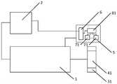
本申请实施例提供一种开关磁阻电机系统,如图1所示,该系统包括:An embodiment of the present application provides a switched reluctance motor system, as shown in FIG. 1 , the system includes:
开关磁阻电机1,其中,开关磁阻电机1为N相开关磁阻电机,开关磁阻电机1中的转子为M极转子,N和M为大于1的正整数;控制器2;第一磁环31,第一磁环31固定在第一磁环支撑件41外侧一周,第一磁环支撑件41与开关磁阻电机1的电机轴相连接,第一磁环31随开关磁阻电机1中的转子同轴转动,其中,第一磁环31包含M个N极和M个S极,M个N极和M个S极相互交替,第一磁环31为径向充磁磁环;传感器板5,传感器板5上设置有输出接口6、N个第一霍尔传感器71和第一信号处理电路81,第一霍尔传感器71通过第一信号处理电路81与输出接口6相连接,输出接口6与控制器2相连接,传感器板5固定于开关磁阻电机1的电机端盖上;其中,第一霍尔传感器71通过检测第一磁环31的转动,获得第一转子位置检测信号,并通过输出接口6将第一转子位置检测信号发送至控制器2,以便控制器2根据多个第一转子位置检测信号计算开关磁阻电机1的转速,以及根据多个第一转子位置检测信号对开关磁阻电机1的相输出进行控制。A switched reluctance motor 1, wherein the switched reluctance motor 1 is an N-phase switched reluctance motor, the rotor in the switched reluctance motor 1 is an M-pole rotor, and N and M are positive integers greater than 1; the controller 2; the first Magnetic ring 31, the first magnetic ring 31 is fixed on the outer side of the first magnetic ring support 41, the first magnetic ring support 41 is connected with the motor shaft of the switched reluctance motor 1, and the first magnetic ring 31 follows the switched reluctance motor The rotor in 1 rotates coaxially, wherein the first magnetic ring 31 includes M N poles and M S poles, M N poles and M S poles alternate with each other, and the first magnetic ring 31 is a radially magnetized magnetic ring sensor board 5, the sensor board 5 is provided with an output interface 6, N first Hall sensors 71 and a first signal processing circuit 81, the first Hall sensor 71 is connected with the output interface 6 through the first signal processing circuit 81 , the output interface 6 is connected with the controller 2, and the sensor board 5 is fixed on the motor end cover of the switched reluctance motor 1; wherein, the first Hall sensor 71 obtains the first rotor position by detecting the rotation of the first magnetic ring 31 detection signal, and send the first rotor position detection signal to the controller 2 through the output interface 6, so that the controller 2 calculates the rotation speed of the switched reluctance motor 1 according to the plurality of first rotor position detection signals, and according to the plurality of first rotor position detection signals The position detection signal controls the phase output of the switched reluctance motor 1 .
其中,开关磁阻电机1具体的结构可以参考现有技术中常用的开关磁阻电机结构,在本申请实施例中对开关磁阻电机1的相数、转子极数、定子极数、体积以及功率等常规参数不进行具体限定;多个第一霍尔传感器71设置在传感器板5上,多个第一霍尔传感器71通过检测第一磁环31的转动,获得第一转子位置检测信号,并通过第一信号处理电路81和输出接口6将第一转子位置检测信号发送至控制器2中;其中,控制器2可以是数字信号处理器(DSP)也可是微控制单元(MCU),控制器2在接收到多个第一霍尔传感器71发送的第一转子位置检测信号后,便可根据多个第一转子位置检测信号生成第一跳变沿波形图,再基于生成的第一跳变沿波形图计算开关磁阻电机1的转速,以及基于生成的第一跳变沿波形图确定开关磁阻电机1对应的当前转子位置,并根据开关磁阻电机1对应的当前转子位置对开关磁阻电机1的相输出进行控制;其中,第一信号处理电路81具体用于对第一霍尔传感器71采集获得的第一转子位置检测信号进行预设处理操作,再通过输出接口6将经过预设处理操作的第一转子位置检测信号发送至控制器2,第一信号处理电路81对第一转子位置检测信号进行的预设处理操作可以但不限于包括:信号滤波处理、信号放大处理等。The specific structure of the switched
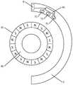
具体的,在本申请实施例中,当开关磁阻电机1为三相开关磁阻电机,其包含的转子为8极转子时,第一磁环31与传感器板5的结构示意图可以如图2所示,第一磁环31固定在第一磁环支撑件41外侧一周,第一磁环31中包含8个N极和8个S极,8个N极和8个S极相互交替,传感器板5上设置有3个第一霍尔传感器71、第一信号处理电路81和输出接口6。Specifically, in the embodiment of the present application, when the switched
本申请实施例提供一种开关磁阻电机系统,与现有技术中通过多个光电开关位置传感器检测光电传感器码盘的转动,获得开关磁阻电机对应的转子位置检测信号相比,本申请实施例在开关磁阻电机的电机轴上设置第一磁环,通过设置在传感器板上的多个第一霍尔传感器通过检测第一磁环的转动,获得第一转子位置检测信号,多个第一霍尔传感器通过输出接口将其获得的第一转子位置检测信号发送至控制器,以便控制器根据多个第一转子位置检测信号计算开关磁阻电机的转速,以及根据多个第一转子位置检测信号对开关磁阻电机的相输出进行控制。由于,磁环的制作工艺较为简单,因此,能够保证第一磁环的加工精度较高,从而能够保证第一霍尔传感器获取得到的第一转子位置检测信号的精度较高,进而能够提高计算开关磁阻电机转速的精度,以及能够提高对开关磁阻电机进行相输出控制的精度。The embodiment of the present application provides a switched reluctance motor system. Compared with the prior art, the rotation of the photoelectric sensor code disc is detected by multiple photoelectric switch position sensors, and the rotor position detection signal corresponding to the switched reluctance motor is obtained. For example, a first magnetic ring is set on the motor shaft of the switched reluctance motor, and the first rotor position detection signal is obtained by detecting the rotation of the first magnetic ring through a plurality of first Hall sensors arranged on the sensor board. A Hall sensor sends the first rotor position detection signal obtained by it to the controller through the output interface, so that the controller calculates the rotation speed of the switched reluctance motor according to the plurality of first rotor position detection signals, and according to the plurality of first rotor positions The detection signal controls the phase output of the switched reluctance motor. Because the manufacturing process of the magnetic ring is relatively simple, the machining accuracy of the first magnetic ring can be ensured to be high, so that the accuracy of the first rotor position detection signal obtained by the first Hall sensor can be guaranteed to be high, and the calculation can be improved. The precision of the rotational speed of the switched reluctance motor, and the precision of phase output control of the switched reluctance motor can be improved.
进一步的,传感器板5上还设置有N个第二霍尔传感器72和第二信号处理电路82,第二霍尔传感器72通过第二信号处理电路82与输出接口6相连接;其中,第二霍尔传感器72通过检测第一磁环31的转动,获得第二转子位置检测信号,并通过输出接口6将第二转子位置检测信号发送至控制器2,以便控制器2根据多个第一转子位置检测信号和多个第二转子位置检测信号计算开关磁阻电机1的转速,以及根据多个第一转子位置检测信号和多个第二转子位置检测信号对开关磁阻电机1的相输出进行控制。在本申请实施例中,多个第二霍尔传感器72设置在传感器板5上,多个第二霍尔传感器72通过检测第一磁环31的转动,获得第二转子位置检测信号,并通过第二信号处理电路82和输出接口6将第二转子位置检测信号发送至控制器2中;控制器2在接收到多个第一霍尔传感器71发送的第一转子位置检测信号和多个第二霍尔传感器72发送的第二转子位置检测信号后,便可根据多个第一转子位置检测信号生成第一跳变沿波形图及根据多个第二转子位置检测信号生成第二跳变沿波形图,并根据第一跳变沿波形图和第二跳变沿波形图生成第三跳变沿波形图,再基于生成的第三跳变沿波形图计算开关磁阻电机1的转速,以及基于生成的第一跳变沿波形图和第三跳变沿波形图确定开关磁阻电机1对应的当前转子位置,并根据开关磁阻电机1对应的当前转子位置对开关磁阻电机1的相输出进行控制;其中,第二信号处理电路82具体用于对第二霍尔传感器72采集获得的第二转子位置检测信号进行预设处理操作,再通过输出接口6将经过预设处理操作的第二转子位置检测信号发送至控制器2,第二信号处理电路82对第二转子位置检测信号进行的预设处理操作可以但不限于包括:信号滤波处理、信号放大处理等。需要进行说明的是,在实际应用过程中,第一信号处理电路81和第二信号处理电路82可以为同一信号处理电路,也可为不同信号处理电路,本申请实施例对此不进行具体限定。由于,第三跳变沿波形图中相邻两条上升边沿和下降边沿之间的边沿间距值比第一跳变沿波形图中相邻两条上升边沿和下降边沿之间的边沿间距值更小,因此,基于第三跳变沿波形图计算开关磁阻电机1的转速及基于第一跳变沿波形图和第三跳变沿波形图对开关磁阻电机1的相输出进行控制,即根据多个第一转子位置检测信号和多个第二转子位置检测信号计算开关磁阻电机1的转速及根据多个第一转子位置检测信号和多个第二转子位置检测信号对开关磁阻电机1的相输出进行控制,能够进一步提高计算开关磁阻电机1转速的精度,以及提高对开关磁阻电机1进行相输出控制的精度。Further, the
进一步的,传感器板5呈圆弧形,传感器板5环绕在第一磁环31外侧,且传感器板5的圆心与第一磁环31的圆心位置相同;其中,N个第一霍尔传感器71沿传感器板5的弧长方向间隔的设置在所述传感器板5上,相邻两个第一霍尔传感器71在传感器板5上的间距弧长对应的圆心角=K1*(360°/M)+360°/(M*N),K1为大于等于0且小于M的整数;N个第二霍尔传感器72沿传感器板5的弧长方向间隔的设置在传感器板5上,相邻两个第二霍尔传感器72在传感器板5上的间距弧长对应的圆心角=K1*(360°/M)+360°/(M*N),K1为大于等于0且小于M的整数;每个第一霍尔传感器71与其对应的第二霍尔传感器72在传感器板5上的间距弧长对应的圆心角=K2*(360°/M)+360°/(4*M),K2为大于等于0且小于M的整数。Further, the sensor board 5 is in the shape of an arc, the sensor board 5 surrounds the outside of the first magnetic ring 31, and the center of the sensor board 5 is the same as the center of the first magnetic ring 31; wherein, the N first Hall sensors 71 The sensors are arranged on the sensor board 5 at intervals along the arc length direction of the sensor board 5, and the central angle corresponding to the arc length of the distance between two adjacent first Hall sensors 71 on the sensor board 5 = K1 *(360°/ M)+360°/(M*N), K1 is an integer greater than or equal to 0 and less than M; N second Hall sensors 72 are arranged on the sensor board 5 at intervals along the arc length direction of the sensor board 5, The central angle corresponding to the arc length of the distance between the adjacent two second Hall sensors 72 on the sensor board 5 = K1 *(360°/M)+360°/(M*N), where K1 is greater than or equal to 0 and less than An integer of M; the central angle corresponding to the arc length of the spacing between each first Hall sensor 71 and its corresponding second Hall sensor 72 on the sensor board 5 = K2 *(360°/M)+360°/(4 *M), K2 is an integer greater than or equal to 0 and less than M.
具体的,在本申请实施例中,当开关磁阻电机1为三相开关磁阻电机,其包含的转子为8极转子,K1=0,K2=2时,第一磁环31与传感器板5的结构示意图可以如图3所示,第一磁环31固定在第一磁环支撑件41外侧一周,第一磁环31中包含8个N极和8个S极,8个N极和8个S极相互交替,传感器板5上设置有3个第一霍尔传感器71(第一霍尔传感器71a、第一霍尔传感器71b和第一霍尔传感器71c)、第一信号处理电路81、3个第二霍尔传感器72(第二霍尔传感器72a、第二霍尔传感器72b和第二霍尔传感器72c)、第二信号处理电路82、和输出接口6;其中,相邻两个第一霍尔传感器71在传感器板5上的间距弧长对应的圆心角=0*(360°/8)+360°/(3*8)=15°,相邻两个第二霍尔传感器72在传感器板5上的间距弧长对应的圆心角=0*(360°/8)+360°/(3*8)=15°,第一霍尔传感器71a与第二霍尔传感器72a在传感器板5上的间距弧长对应的圆心角=2*(360°/8)+360°/(4*8)=101.25°、第一霍尔传感器71b与第二霍尔传感器72b在传感器板5上的间距弧长对应的圆心角=2*(360°/8)+360°/(4*8)=101.25°、第一霍尔传感器71c与第二霍尔传感器72c在传感器板5上的间距弧长对应的圆心角=2*(360°/8)+360°/(4*8)=101.25°。Specifically, in the embodiment of the present application, when the switched
进一步的,开关磁阻电机系统中还包括:第二磁环32,第二磁环32固定在第二磁环支撑件42外侧一周,第二磁环支撑件42与开关磁阻电机1的电机轴相连接,第二磁环32随所述开关磁阻电机1中的转子同轴转动,其中,第二磁环32包含X个N极和X个S极,X个N极和X个S极相互交替,第二磁环32为径向充磁磁环,X为M的整数倍;传感器板5上还设置有Y个第三霍尔传感器73和第三信号处理电路83,第三霍尔传感器73通过第三信号处理电路83与输出接口6相连接,Y为大于等于1的正整数;其中,第三霍尔传感器73通过检测第二磁环32的转动,获得第三转子位置检测信号,并通过输出接口6将第三转子位置检测信号发送至控制器2,以便控制器2根据至少一个第三转子位置检测信号计算开关磁阻电机1的转速,以及根据多个第一转子位置检测信号和至少一个第三转子位置检测信号对开关磁阻电机1的相输出进行控制。具体的,在实际应用过程中,可以将第一磁环31和第二磁环32设置为:第一磁环31的任意一个NS极交界和其对应的第二磁环32的NS极交界所在平面,与开关磁阻电机1的电机轴相平行,但不限于此。Further, the switched reluctance motor system further includes: a second
在本申请实施例中,至少一个第三霍尔传感器73设置在传感器板5上,至少一个第三霍尔传感器73通过检测第二磁环32的转动,获得第三转子位置检测信号,并通过第三信号处理电路83和输出接口6将第三转子位置检测信号发送至控制器2中;控制器2在接收到多个第一霍尔传感器71发送的第一转子位置检测信号和至少一个第三霍尔传感器73发送的第三转子位置检测信号后,便可根据多个第一转子位置检测信号生成第一跳变沿波形图及根据至少一个第三转子位置检测信号生成第四跳变沿波形图,再基于生成的第四跳变沿波形图计算开关磁阻电机1的转速,以及基于生成的第一跳变沿波形图和第四跳变沿波形图确定开关磁阻电机1对应的当前转子位置,并根据开关磁阻电机1对应的当前转子位置对开关磁阻电机1的相输出进行控制;其中,第三信号处理电路83具体用于对第三霍尔传感器73采集获得的第三转子位置检测信号进行预设处理操作,再通过输出接口6将经过预设处理操作的第三转子位置检测信号发送至控制器2,第三信号处理电路83对第三转子位置检测信号进行的预设处理操作可以但不限于包括:信号滤波处理、信号放大处理等。需要进行说明的是,在实际应用过程中,第一信号处理电路81和第三信号处理电路83可以为同一信号处理电路,也可为不同信号处理电路,本申请实施例对此不进行具体限定。由于,第四跳变沿波形图中相邻两条上升边沿和下降边沿之间的边沿间距值比第一跳变沿波形图中相邻两条上升边沿和下降边沿之间的边沿间距值更小,因此,基于第四跳变沿波形图计算开关磁阻电机1的转速及基于第一跳变沿波形图和第四跳变沿波形图对开关磁阻电机11的相输出进行控制,即根据至少一个第三转子位置检测信号计算开关磁阻电机1的转速及根据多个第一转子位置检测信号和至少一个第三转子位置检测信号对开关磁阻电机1的相输出进行控制,能够进一步提高计算开关磁阻电机1转速的精度,以及提高对开关磁阻电机1进行相输出控制的精度。In the embodiment of the present application, at least one third Hall sensor 73 is provided on the
进一步的,第一磁环31与第二磁环32之间设置有磁屏蔽板;传感器板5呈圆弧形,传感器板5环绕在第一磁环31和第二磁环32外侧,且传感器板5的圆心与第一磁环31的圆心、第二磁环32的圆心位置相同;N个第一霍尔传感器71沿传感器板5的弧长方向间隔的设置在传感器板5上,相邻两个第一霍尔传感器71在传感器板5上的间距弧长对应的圆心角=K1*(360°/M)+360°/(M*N),K1为大于等于0且小于M的整数;Y个第三霍尔传感器73沿传感器板5的弧长方向间隔的设置在传感器板5上,相邻两个第三霍尔传感器73在传感器板5上的间距弧长对应的圆心角=K3*(360°/X)+360°/(Y*X),K3为大于等于0且小于X的整数,其中,N个第一霍尔传感器71与Y个第三霍尔传感器73并排的设置在传感器板5的宽度方向上。具体的,在实际应用过程中,Y个第三霍尔传感器73中的第一个第三霍尔传感器73的中心点和N个第一霍尔传感器71中的第一个第一霍尔传感器71的中心点所在直线,与开关磁阻电机1的电机轴相平行,但不限于此。Further, a magnetic shielding plate is arranged between the first magnetic ring 31 and the second magnetic ring 32; the sensor plate 5 is in the shape of an arc, the sensor plate 5 surrounds the outside of the first magnetic ring 31 and the second magnetic ring 32, and the sensor The center of the plate 5 is the same as the center of the first magnetic ring 31 and the center of the second magnetic ring 32; The central angle corresponding to the arc length of the distance between the two first Hall sensors 71 on the sensor board 5 = K1 *(360°/M)+360°/(M*N), where K1 is greater than or equal to 0 and less than M Y third Hall sensors 73 are arranged on the sensor board 5 at intervals along the arc length direction of the sensor board 5, and the distance between two adjacent third Hall sensors 73 on the sensor board 5 corresponds to the arc length of the center of the circle Angle=K3 *(360°/X)+360°/(Y*X), K3 is an integer greater than or equal to 0 and less than X, wherein N first Hall sensors 71 and Y third Hall sensors The sensors 73 are arranged side by side in the width direction of the sensor board 5 . Specifically, in the actual application process, the center point of the first third Hall sensor 73 of the Y third Hall sensors 73 and the first first Hall sensor of the N
具体的,在本申请实施例中,传感器板5的结构示意图可以如图4a所示,传感器板5包含6个表面,上表面、与上表面相对的下表面、左侧面、与左侧面相对的右侧面、内侧面、与内侧面相对的外侧面;在实际应用过程中,可以将N个第一霍尔传感器71设置在传感器板5的下表面,将Y个第三霍尔传感器73设置在传感器板5的上表面;也可以将N个第一霍尔传感器71和Y个第三霍尔传感器73设置在传感器板5的内侧面,本申请实施例对此不进行具体限定。Specifically, in this embodiment of the present application, a schematic structural diagram of the
具体的,在本申请实施例中,当开关磁阻电机1为三相开关磁阻电机,其包含的转子为8极转子时,第二磁环32的结构示意图可以如图4b所示,第二磁环32固定在第二磁环支撑件42外侧一周,第二磁环32包含16个N极和16个S极,16个N极和16个S极相互交替;当传感器板5上设置有3个第三霍尔传感器73,K1=0,K3=1时,传感器板5的结构示意图可以如图4c所示,传感器板5的内侧面上设置有3个第一霍尔传感器71(第一霍尔传感器71a、第一霍尔传感器71b和第一霍尔传感器71c)、第一信号处理电路81、3个第三霍尔传感器73(第三霍尔传感器73a、第三霍尔传感器73b和第三霍尔传感器73c)、第三信号处理电路83、和输出接口6;其中,相邻两个第一霍尔传感器71在传感器板5上的间距弧长对应的圆心角=0*(360°/8)+360°/(3*8)=15°,相邻两个第三霍尔传感器73在传感器板5上的间距弧长对应的圆心角=(360°/16)+360°/(3*16)=30°,三个第一霍尔传感器71与三个第三霍尔传感器73并排的设置在传感器板的宽度方向上,且第三霍尔传感器73a的中心点与第一霍尔传感器71a的中心点,所在直线与开关磁阻电机1的电机轴相平行。Specifically, in the embodiment of the present application, when the switched
本申请实施例提供了一种转速检测方法,该方法应用于上述的开关磁阻电机系统中,如图5所示,该方法包括:An embodiment of the present application provides a rotational speed detection method, which is applied to the above-mentioned switched reluctance motor system. As shown in FIG. 5 , the method includes:
101、接收多个第一霍尔传感器发送的第一转子位置检测信号。101. Receive a first rotor position detection signal sent by a plurality of first Hall sensors.
在本申请实施例中,各个步骤中的执行主体为开关磁阻电机系统中的控制器。设置在传感器板上的多个第一霍尔传感器通过检测第一磁环的转动,获得第一转子位置检测信号,并通过输出接口将其获得的第一转子位置检测信号发送至控制器,此时,控制器便能接收到多个第一霍尔传感器发送的第一转子位置检测信号。In the embodiments of the present application, the executing subject in each step is the controller in the switched reluctance motor system. The plurality of first Hall sensors arranged on the sensor board obtain the first rotor position detection signal by detecting the rotation of the first magnetic ring, and send the obtained first rotor position detection signal to the controller through the output interface. At the time, the controller can receive the first rotor position detection signals sent by the plurality of first Hall sensors.
102、根据多个第一转子位置检测信号生成第一跳变沿波形图。102. Generate a first transition edge waveform diagram according to the plurality of first rotor position detection signals.
在本申请实施例中,控制器在接收到多个第一霍尔传感器发送的第一转子位置检测信号后,便可根据多个第一转子位置检测信号生成第一跳变沿波形图。具体的,在本步骤中,控制器可以通过对多个第一转子位置检测信号进行逻辑运算,来生成第一跳变沿波形图,但不限于此。In the embodiment of the present application, after receiving the first rotor position detection signals sent by the plurality of first Hall sensors, the controller can generate the first transition edge waveform diagram according to the plurality of first rotor position detection signals. Specifically, in this step, the controller may generate the waveform diagram of the first transition edge by performing logical operations on the plurality of first rotor position detection signals, but is not limited thereto.
103、根据第一跳变沿波形图计算开关磁阻电机对应的转速。103. Calculate the rotational speed corresponding to the switched reluctance motor according to the waveform diagram of the first transition edge.
在本申请实施例中,控制器在根据多个第一转子位置检测信号生成第一跳变沿波形图后,便可根据生成的第一跳变沿波形图计算开关磁阻电机对应的转速。In the embodiment of the present application, after the controller generates the first transition edge waveform diagram according to the plurality of first rotor position detection signals, the controller can calculate the corresponding rotational speed of the switched reluctance motor according to the generated first transition edge waveform diagram.
具体的,在本步骤中,任意第一转子位置检测信号中的一个电角度周期为360°,电角度周期具体分为A个位置计数值,控制器可以通过以下方式根据第一跳变沿波形图计算开关磁阻电机对应的转速:首先,控制器根据第一上升边沿对应的位置计数值和第一下降边沿对应的位置计数值,确定第一跳变沿波形图对应的边沿间距值,即当第一上升边沿对应的位置计数值大于第一下降边沿对应的位置计数值时,将第一上升边沿对应的位置计数值与第一下降边沿对应的位置计数值的差值,确定为第一跳变沿波形图对应的边沿间距值,当第一上升边沿对应的位置计数值小于第一下降边沿对应的位置计数值,将第一下降边沿对应的位置计数值与第一上升边沿对应的位置计数值的差值,确定为第一跳变沿波形图对应的边沿间距值,其中,第一上升边沿和第一下降边沿为第一跳变沿波形图中任意相邻的上升边沿和下降边沿;然后,控制器通过第一定时器获取第一上升边沿对应的捕捉时刻和第一下降边沿对应的捕捉时刻;其次,控制器根据第一上升边沿对应的捕捉时刻和第一下降边沿对应的捕捉时刻确定第一跳变沿波形图对应的捕获周期,即当第一上升边沿对应的捕捉时刻大于第一下降边沿对应的捕捉时刻时,将第一上升边沿对应的捕捉时刻与第一下降边沿对应的捕捉时刻的差值,确定为第一跳变沿波形图对应的捕获周期,当第一上升边沿对应的捕捉时刻小于第一下降边沿对应的捕捉时刻时,将第一下降边沿对应的捕捉时刻与第一上升边沿对应的捕捉时刻的差值,确定为第一跳变沿波形图对应的捕获周期;最后,控制器根据第一跳变沿波形图对应的边沿间距值、第一跳变沿波形图对应的捕获周期和预置转速计算常数,计算开关磁阻电机对应的转速,即将第一跳变沿波形图对应的边沿间距值、第一跳变沿波形图对应的捕获周期和预置转速计算常数代入第一预设公式中,从而计算开关磁阻电机对应的转速,其中,预置转速计算常数为根据开关磁阻电机对应的电机相数N、转子极数M和位置计数值A确定的;第一预设公式具体如下:Specifically, in this step, an electrical angle period in any first rotor position detection signal is 360°, and the electrical angle period is specifically divided into A position count values. The controller can use the following methods according to the first transition edge waveform. Figure 1. Calculate the speed corresponding to the switched reluctance motor: First, the controller determines the edge spacing value corresponding to the waveform diagram of the first transition edge according to the position count value corresponding to the first rising edge and the position count value corresponding to the first falling edge, that is, When the position count value corresponding to the first rising edge is greater than the position count value corresponding to the first falling edge, the difference between the position count value corresponding to the first rising edge and the position count value corresponding to the first falling edge is determined as the first The edge spacing value corresponding to the transition edge waveform diagram. When the position count value corresponding to the first rising edge is smaller than the position count value corresponding to the first falling edge, the position count value corresponding to the first falling edge is compared with the position corresponding to the first rising edge. The difference between the count values is determined as the edge spacing value corresponding to the waveform diagram of the first transition edge, where the first rising edge and the first falling edge are any adjacent rising edge and falling edge in the waveform diagram of the first transition edge Then, the controller obtains the capture time corresponding to the first rising edge and the capture time corresponding to the first falling edge through the first timer; secondly, the controller obtains the capture time corresponding to the first rising edge and the corresponding capture time of the first falling edge according to the first rising edge. Time to determine the capture period corresponding to the first transition edge waveform diagram, that is, when the capture time corresponding to the first rising edge is greater than the capture time corresponding to the first falling edge, the capture time corresponding to the first rising edge corresponds to the first falling edge. The difference between the capture moments is determined as the capture period corresponding to the waveform diagram of the first transition edge. When the capture time corresponding to the first rising edge is smaller than the capture time corresponding to the first falling edge, the capture time corresponding to the first falling edge The difference value of the capture time corresponding to the first rising edge is determined as the capture period corresponding to the waveform diagram of the first transition edge. The capture period corresponding to the waveform diagram and the preset speed calculation constant, and the corresponding rotation speed of the switched reluctance motor is calculated, that is, the edge spacing value corresponding to the waveform diagram of the first transition edge, and the capture period and preset corresponding to the waveform diagram of the first transition edge. The rotation speed calculation constant is substituted into the first preset formula to calculate the rotation speed corresponding to the switched reluctance motor, wherein the preset rotation speed calculation constant is based on the motor phase number N, the rotor pole number M and the position count value A corresponding to the switched reluctance motor The first preset formula is as follows:
v=m*Kv/Tv=m*Kv/T
其中,v为开关磁阻电机对应的转速,m为第一跳变沿波形图对应的边沿间距值,Kv为预置转速计算常数,T为第一跳变沿波形图对应的捕获周期。Among them, v is the speed corresponding to the switched reluctance motor, m is the edge spacing value corresponding to the waveform diagram of the first transition edge, Kv is the preset speed calculation constant, and T is the capture period corresponding to the waveform diagram of the first transition edge.
进一步的,在本申请实施例中,控制器在根据第一跳变沿波形图计算开关磁阻电机对应的转速后,还可以根据第一跳变沿波形图对开关磁阻电机的相输出进行控制:基于预设时间间隔,即每经过预设时间间隔,通过第二定时器获取第一目标边沿对应的捕捉时刻和当前时刻,其中,第一目标边沿为第一跳变沿波形图中捕捉时刻小于当前时刻,且捕捉时刻与当前时刻最接近的上升边沿或下降边沿,预设时间间隔可以但不限于为:1ms、3ms、5ms等等;获取电机旋转方向;根据第一目标边沿对应的位置计数值、第一跳变沿波形图对应的边沿间距值、第一目标边沿对应的捕捉时刻、当前时刻、第一跳变沿波形图对应的捕获周期和电机旋转方向,计算当前转子位置计数值,即当电机旋转方向为正向时,将第一目标边沿对应的位置计数值、第一跳变沿波形图对应的边沿间距值、第一目标边沿对应的捕捉时刻、当前时刻和第一跳变沿波形图对应的捕获周期代入第二预设公式中,从而计算开关磁阻电机对应的当前转子位置计数值,第二预设公式具体如下:Further, in the embodiment of the present application, after the controller calculates the corresponding rotational speed of the switched reluctance motor according to the waveform diagram of the first transition edge, the controller can also perform phase output of the switched reluctance motor according to the waveform diagram of the first transition edge. Control: Based on the preset time interval, that is, every preset time interval, the second timer is used to obtain the capture time and the current time corresponding to the first target edge, where the first target edge is captured in the waveform diagram of the first transition edge The time is less than the current time, and the rising edge or falling edge that captures the time closest to the current time, the preset time interval can be but not limited to: 1ms, 3ms, 5ms, etc.; obtain the motor rotation direction; according to the corresponding first target edge Position count value, edge spacing value corresponding to the first transition edge waveform, capture time corresponding to the first target edge, current time, capture period and motor rotation direction corresponding to the first transition waveform, and calculate the current rotor position count value, that is, when the rotation direction of the motor is forward, the position count value corresponding to the first target edge, the edge distance value corresponding to the waveform diagram of the first transition edge, the capture time corresponding to the first target edge, the current time and the first The capture period corresponding to the transition edge waveform is substituted into the second preset formula to calculate the current rotor position count value corresponding to the switched reluctance motor. The second preset formula is as follows:
Ai=An+m*(t1-t2)/TAi=An+m*(t1-t2)/T
其中,Ai为开关磁阻电机对应的当前转子位置计数值,An为第一目标边沿对应的位置计数值,m为第一跳变沿波形图对应的边沿间距值,t1为当前时刻,t2为第一目标边沿对应的捕捉时刻,T为第一跳变沿波形图对应的捕获周期;Among them, Ai is the current rotor position count value corresponding to the switched reluctance motor, An is the position count value corresponding to the first target edge, m is the edge spacing value corresponding to the waveform diagram of the first transition edge, t1 is the current moment, t2 is The capture time corresponding to the first target edge, T is the capture period corresponding to the waveform diagram of the first transition edge;
当电机旋转方向为反向时,将第一目标边沿对应的位置计数值、第一跳变沿波形图对应的边沿间距值、第一目标边沿对应的捕捉时刻、当前时刻和第一跳变沿波形图对应的捕获周期代入第三预设公式中,从而计算开关磁阻电机对应的当前转子位置计数值,第三预设公式具体如下:When the rotation direction of the motor is reversed, the position count value corresponding to the first target edge, the edge spacing value corresponding to the waveform diagram of the first transition edge, the capture time corresponding to the first target edge, the current time and the first transition edge The capture period corresponding to the waveform is substituted into the third preset formula to calculate the current rotor position count value corresponding to the switched reluctance motor. The third preset formula is as follows:
Ai=An-m*(t1-t2)/TAi=An-m*(t1-t2)/T
其中,Ai为开关磁阻电机对应的当前转子位置计数值,An为第一目标边沿对应的位置计数值,m为第一跳变沿波形图对应的边沿间距值,t1为当前时刻,t2为第一目标边沿对应的捕捉时刻,T为第一跳变沿波形图对应的捕获周期;将开关磁阻电机对应的当前转子位置计数值与预置控制参数进行比对,并根据比对结果进行相输出控制,其中,预置控制参数可以但不限于包括:预置开通角对应的位置计数范围、预置关断角对应的位置计数范围等;其中,控制器具体如何根据开关磁阻电机对应的当前转子位置计数值与预置控制参数的比对结果,对开关磁阻电机进行相输出控制,可以参考现有相关技术,本申请实施例对此不再赘述。Among them, Ai is the current rotor position count value corresponding to the switched reluctance motor, An is the position count value corresponding to the first target edge, m is the edge spacing value corresponding to the waveform diagram of the first transition edge, t1 is the current moment, t2 is The capture time corresponding to the first target edge, T is the capture period corresponding to the waveform diagram of the first transition edge; compare the current rotor position count value corresponding to the switched reluctance motor with the preset control parameters, and carry out Phase output control, wherein the preset control parameters may include but are not limited to: the position count range corresponding to the preset turn-on angle, the position count range corresponding to the preset turn-off angle, etc.; wherein, how the controller specifically corresponds to the switched reluctance motor The comparison result of the current rotor position count value and the preset control parameters, to control the phase output of the switched reluctance motor, reference may be made to the related art, which will not be repeated in this embodiment of the present application.
进一步的,在本申请实施例中,传感器板上除了设置有多个第一霍尔传感器外,还设置有多个第二霍尔传感器,多个第一霍尔传感器通过检测第一磁环的转动,获得第一转子位置检测信号,并通过输出接口将其获得的第一转子位置检测信号发送至控制器,多个第二霍尔传感器通过检测第一磁环的转动,获得第二转子位置检测信号,并通过输出接口将其获得的第二转子位置检测信号发送至控制器,此时,控制器便能接收到多个第一霍尔传感器发送的第一转子位置检测信号和多个第二霍尔传感器发送的第二转子位置检测信号,其中,任意第一转子位置检测信号中的一个电角度周期为360°,电角度周期具体分为A个位置计数值,任意第二转子位置检测信号中的一个电角度周期为360°,电角度周期具体分为A个位置计数值;控制器在接收到多个第一霍尔传感器发送的第一转子位置检测信号和多个第二霍尔传感器发送的第二转子位置检测信号后,便可根据多个第一转子位置检测信号生成第一跳变沿波形图,以及根据多个第二转子位置检测信号生成第二跳变沿波形图,再根据第一跳变沿波形图和第二跳变沿波形图,生成第三跳变沿波形图,具体的,控制器可以通过对多个第一转子位置检测信号进行逻辑运算,来生成第一跳变沿波形图,通过对多个第二转子位置检测信号进行逻辑运算,来生成第二跳变沿波形图,以及通过对第一跳变沿波形图和第二跳变沿波形图进行逻辑运算,来生成第三跳变沿波形图,但不限于此;控制器在生成第三跳变沿波形图后,便可根据第二上升边沿对应的位置计数值和第二下降边沿对应的位置计数值,确定第三跳变沿波形图对应的边沿间距值,即当第二上升边沿对应的位置计数值大于第二下降边沿对应的位置计数值时,将第二上升边沿对应的位置计数值与第二下降边沿对应的位置计数值的差值,确定为第三跳变沿波形图对应的边沿间距值,当第二上升边沿对应的位置计数值小于第二下降边沿对应的位置计数值,将第二下降边沿对应的位置计数值与第二上升边沿对应的位置计数值的差值,确定为第三跳变沿波形图对应的边沿间距值,其中,第二上升边沿和第二下降边沿为第三跳变沿波形图中任意相邻的上升边沿和下降边沿;控制器在确定第三跳变沿波形图对应的边沿间距值后,便可通过第一定时器获取第二上升边沿对应的捕捉时刻和第二下降边沿对应的捕捉时刻,并根据第二上升边沿对应的捕捉时刻和第二下降边沿对应的捕捉时刻确定第三跳变沿波形图对应的捕获周期,即当第二上升边沿对应的捕捉时刻大于第二下降边沿对应的捕捉时刻时,将第二上升边沿对应的捕捉时刻与第二下降边沿对应的捕捉时刻的差值,确定为第三跳变沿波形图对应的捕获周期,当第二上升边沿对应的捕捉时刻小于第二下降边沿对应的捕捉时刻时,将第二下降边沿对应的捕捉时刻与第二上升边沿对应的捕捉时刻的差值,确定为第三跳变沿波形图对应的捕获周期;最后,控制器便可根据第三跳变沿波形图对应的边沿间距值、第三跳变沿波形图对应的捕获周期和预置转速计算常数,计算开关磁阻电机对应的转速,即将第三跳变沿波形图对应的边沿间距值、第三跳变沿波形图对应的捕获周期和预置转速计算常数代入第一预设公式中,从而计算开关磁阻电机对应的转速,其中,预置转速计算常数为根据开关磁阻电机对应的电机相数N、转子极数M和位置计数值A确定的;第一预设公式具体如下:Further, in the embodiment of the present application, in addition to a plurality of first Hall sensors, the sensor board is also provided with a plurality of second Hall sensors, and the plurality of first Hall sensors detect the Rotate to obtain the first rotor position detection signal, and send the obtained first rotor position detection signal to the controller through the output interface, and a plurality of second Hall sensors obtain the second rotor position by detecting the rotation of the first magnetic ring detection signal, and send the obtained second rotor position detection signal to the controller through the output interface, at this time, the controller can receive the first rotor position detection signal sent by multiple first Hall sensors and multiple first rotor position detection signals The second rotor position detection signal sent by the two Hall sensors, wherein one electrical angle period in any first rotor position detection signal is 360°, and the electrical angle period is specifically divided into A position count values. Any second rotor position detection signal An electrical angle cycle in the signal is 360°, and the electrical angle cycle is specifically divided into A position count values; the controller receives the first rotor position detection signal sent by multiple first Hall sensors and multiple second Hall sensors. After the second rotor position detection signal sent by the sensor, the waveform diagram of the first transition edge can be generated according to the plurality of first rotor position detection signals, and the waveform diagram of the second transition edge can be generated according to the plurality of second rotor position detection signals, Then, according to the waveform diagram of the first jumping edge and the waveform diagram of the second jumping edge, the third jumping edge waveform diagram is generated. For a transition edge waveform diagram, the second transition edge waveform diagram is generated by performing logical operations on a plurality of second rotor position detection signals, and the first transition edge waveform diagram and the second transition edge waveform diagram are processed logic operation to generate the third transition edge waveform diagram, but not limited to this; after the controller generates the third transition edge waveform diagram, it can count according to the position corresponding to the second rising edge and the second falling edge. Position count value, determine the edge spacing value corresponding to the waveform diagram of the third transition edge, that is, when the position count value corresponding to the second rising edge is greater than the position count value corresponding to the second falling edge, the position corresponding to the second rising edge is counted The difference between the value and the position count value corresponding to the second falling edge is determined as the edge spacing value corresponding to the waveform diagram of the third transition edge. When the position count value corresponding to the second rising edge is smaller than the position count value corresponding to the second falling edge , the difference between the position count value corresponding to the second falling edge and the position count value corresponding to the second rising edge is determined as the edge spacing value corresponding to the waveform diagram of the third transition edge, wherein the second rising edge and the second falling edge The edge is any adjacent rising edge and falling edge in the waveform diagram of the third transition edge; after the controller determines the edge spacing value corresponding to the waveform diagram of the third transition edge, the controller can obtain the second rising edge through the first timer The corresponding capture time and the capture time corresponding to the second falling edge, and the capture period corresponding to the waveform diagram of the third transition edge is determined according to the capture time corresponding to the second rising edge and the capture time corresponding to the second falling edge. The capture time corresponding to the rising edge is greater than the first When the capture time corresponds to the second falling edge, the difference between the capture time corresponding to the second rising edge and the capture time corresponding to the second falling edge is determined as the capture period corresponding to the waveform diagram of the third transition edge. When the corresponding capture time is less than the capture time corresponding to the second falling edge, the difference between the capture time corresponding to the second falling edge and the capture time corresponding to the second rising edge is determined as the capture period corresponding to the waveform diagram of the third transition edge ; Finally, the controller can calculate the constant according to the edge spacing value corresponding to the waveform diagram of the third transition edge, the capture period corresponding to the waveform diagram of the third transition edge, and the preset rotational speed, and calculate the rotational speed corresponding to the switched reluctance motor, that is, the first The edge spacing value corresponding to the waveform diagram of the three transition edges, the capture period corresponding to the waveform diagram of the third transition edge, and the preset rotation speed calculation constant are substituted into the first preset formula, so as to calculate the rotation speed corresponding to the switched reluctance motor. The speed calculation constant is determined according to the motor phase number N, the rotor pole number M and the position count value A corresponding to the switched reluctance motor; the first preset formula is specifically as follows:
v=m*Kv/Tv=m*Kv/T
其中,v为开关磁阻电机对应的转速,m为第三跳变沿波形图对应的边沿间距值,Kv为预置转速计算常数,T为第三跳变沿波形图对应的捕获周期。Among them, v is the speed corresponding to the switched reluctance motor, m is the edge spacing value corresponding to the waveform diagram of the third transition edge, Kv is the preset speed calculation constant, and T is the capture period corresponding to the waveform diagram of the third transition edge.
进一步的,在本申请实施例中,控制器在根据第三跳变沿波形图计算开关磁阻电机对应的转速后,还可以根据第三跳变沿波形图对开关磁阻电机的相输出进行控制:基于预设时间间隔,即每经过预设时间间隔,通过第二定时器获取第二目标边沿对应的捕捉时刻和当前时刻,其中,第二目标边沿为第三跳变沿波形图中捕捉时刻小于当前时刻,且捕捉时刻与当前时刻最接近的上升边沿或下降边沿,预设时间间隔可以但不限于为:1ms、3ms、5ms等等;获取电机旋转方向;根据第二目标边沿对应的位置计数值、第三跳变沿波形图对应的边沿间距值、第二目标边沿对应的捕捉时刻、当前时刻、第三跳变沿波形图对应的捕获周期和电机旋转方向,计算当前转子位置计数值,即当电机旋转方向为正向时,将第二目标边沿对应的位置计数值、第三跳变沿波形图对应的边沿间距值、第二目标边沿对应的捕捉时刻、当前时刻和第三跳变沿波形图对应的捕获周期代入第二预设公式中,从而计算开关磁阻电机对应的当前转子位置计数值,第二预设公式具体如下:Further, in the embodiment of the present application, after the controller calculates the corresponding rotational speed of the switched reluctance motor according to the waveform diagram of the third transition edge, the controller can also perform phase output of the switched reluctance motor according to the waveform diagram of the third transition edge. Control: Based on the preset time interval, that is, every preset time interval, the capture time and current time corresponding to the second target edge are obtained through the second timer, where the second target edge is captured in the waveform diagram of the third transition edge The time is less than the current time, and the rising edge or falling edge that captures the time closest to the current time, the preset time interval can be but not limited to: 1ms, 3ms, 5ms, etc.; obtain the motor rotation direction; according to the second target edge corresponding Position count value, edge spacing value corresponding to the third transition edge waveform, capture time corresponding to the second target edge, current time, capture period and motor rotation direction corresponding to the third transition waveform, and calculate the current rotor position count value, that is, when the rotation direction of the motor is forward, the position count value corresponding to the second target edge, the edge spacing value corresponding to the waveform diagram of the third transition edge, the capture time corresponding to the second target edge, the current time and the third The capture period corresponding to the transition edge waveform is substituted into the second preset formula to calculate the current rotor position count value corresponding to the switched reluctance motor. The second preset formula is as follows:
Ai=An+m*(t1-t2)/TAi=An+m*(t1-t2)/T
其中,Ai为开关磁阻电机对应的当前转子位置计数值,An为第二目标边沿对应的位置计数值,m为第三跳变沿波形图对应的边沿间距值,t1为当前时刻,t2为第二目标边沿对应的捕捉时刻,T为第三跳变沿波形图对应的捕获周期;Among them, Ai is the current rotor position count value corresponding to the switched reluctance motor, An is the position count value corresponding to the second target edge, m is the edge spacing value corresponding to the waveform diagram of the third transition edge, t1 is the current moment, and t2 is the The capture time corresponding to the second target edge, T is the capture period corresponding to the waveform diagram of the third transition edge;
当电机旋转方向为反向时,将第二目标边沿对应的位置计数值、第三跳变沿波形图对应的边沿间距值、第二目标边沿对应的捕捉时刻、当前时刻和第三跳变沿波形图对应的捕获周期代入第三预设公式中,从而计算开关磁阻电机对应的当前转子位置计数值,第三预设公式具体如下:When the rotation direction of the motor is reversed, the position count value corresponding to the second target edge, the edge spacing value corresponding to the waveform diagram of the third transition edge, the capture moment corresponding to the second target edge, the current moment and the third transition edge The capture period corresponding to the waveform is substituted into the third preset formula to calculate the current rotor position count value corresponding to the switched reluctance motor. The third preset formula is as follows:
Ai=An-m*(t1-t2)/TAi=An-m*(t1-t2)/T
其中,Ai为开关磁阻电机对应的当前转子位置计数值,An为第二目标边沿对应的位置计数值,m为第三跳变沿波形图对应的边沿间距值,t1为当前时刻,t2为第二目标边沿对应的捕捉时刻,T为第三跳变沿波形图对应的捕获周期;将开关磁阻电机对应的当前转子位置计数值与预置控制参数进行比对,并根据比对结果进行相输出控制,其中,预置控制参数可以但不限于包括:预置开通角对应的位置计数范围、预置关断角对应的位置计数范围等;其中,控制器具体如何根据开关磁阻电机对应的当前转子位置计数值与预置控制参数的比对结果,对开关磁阻电机进行相输出控制,可以参考现有相关技术,本申请实施例对此不再赘述。Among them, Ai is the current rotor position count value corresponding to the switched reluctance motor, An is the position count value corresponding to the second target edge, m is the edge spacing value corresponding to the waveform diagram of the third transition edge, t1 is the current moment, and t2 is the The capture time corresponding to the second target edge, T is the capture period corresponding to the waveform of the third transition edge; compare the current rotor position count value corresponding to the switched reluctance motor with the preset control parameters, and carry out Phase output control, wherein the preset control parameters may include but are not limited to: the position count range corresponding to the preset turn-on angle, the position count range corresponding to the preset turn-off angle, etc.; wherein, how the controller specifically corresponds to the switched reluctance motor The comparison result of the current rotor position count value and the preset control parameters, to control the phase output of the switched reluctance motor, reference may be made to the related art, which will not be repeated in this embodiment of the present application.
进一步的,在本申请实施例中,传感器板上除了设置有多个第一霍尔传感器外,还设置有至少一个第三霍尔传感器,多个第一霍尔传感器通过检测第一磁环的转动,获得第一转子位置检测信号,并通过输出接口将其获得的第一转子位置检测信号发送至控制器,至少一个第三霍尔传感器通过检测第二磁环的转动,获得第三转子位置检测信号,并通过输出接口将其获得的第三转子位置检测信号发送至控制器,此时,控制器便能接收到多个第一霍尔传感器发送的第一转子位置检测信号和至少一个第三霍尔传感器发送的第三转子位置检测信号,其中,任意第一转子位置检测信号中的一个电角度周期为360°,电角度周期具体分为A个位置计数值;控制器在接收到多个第一霍尔传感器发送的第一转子位置检测信号和至少一个第三霍尔传感器发送的第三转子位置检测信号后,便可根据多个第一转子位置检测信号生成第一跳变沿波形图,以及根据至少一个第三转子位置检测信号生成第四跳变沿波形图,具体的,控制器可以通过对多个第一转子位置检测信号进行逻辑运算,来生成第一跳变沿波形图,以及通过对至少一个第三转子位置检测信号进行逻辑运算,来生成第四跳变沿波形图,但不限于此;控制器在生成第四跳变沿波形图后,便可根据第一跳变沿波形图中每个上升边沿对应的位置计数值和每个下降边沿对应的位置计数值,确定第四跳变沿波形图中每个上升边沿对应的位置计数值和每个下降边沿对应的位置计数值;控制器在确定第四跳变沿波形图中每个上升边沿对应的位置计数值和每个下降边沿对应的位置计数值后,便可根据第三上升边沿对应的位置计数值和第三下降边沿对应的位置计数值,确定第四跳变沿波形图对应的边沿间距值,即当第三上升边沿对应的位置计数值大于第三下降边沿对应的位置计数值时,将第三上升边沿对应的位置计数值与第三下降边沿对应的位置计数值的差值,确定为第四跳变沿波形图对应的边沿间距值,当第三上升边沿对应的位置计数值小于第三下降边沿对应的位置计数值,将第三下降边沿对应的位置计数值与第三上升边沿对应的位置计数值的差值,确定为第四跳变沿波形图对应的边沿间距值,其中,第三上升边沿和第三下降边沿为第四跳变沿波形图中任意相邻的上升边沿和下降边沿;控制器在确定第四跳变沿波形图对应的边沿间距值后,便可通过第一定时器获取第三上升边沿对应的捕捉时刻和第三下降边沿对应的捕捉时刻,并根据第三上升边沿对应的捕捉时刻和第三下降边沿对应的捕捉时刻确定第四跳变沿波形图对应的捕获周期,即当第三上升边沿对应的捕捉时刻大于第三下降边沿对应的捕捉时刻时,将第三上升边沿对应的捕捉时刻与第三下降边沿对应的捕捉时刻的差值,确定为第四跳变沿波形图对应的捕获周期,当第三上升边沿对应的捕捉时刻小于第三下降边沿对应的捕捉时刻时,将第三下降边沿对应的捕捉时刻与第三上升边沿对应的捕捉时刻的差值,确定为第四跳变沿波形图对应的捕获周期;最后,控制器便可根据第四跳变沿波形图对应的边沿间距值、第四跳变沿波形图对应的捕获周期和预置转速计算常数,计算开关磁阻电机对应的转速,即将第四跳变沿波形图对应的边沿间距值、第四跳变沿波形图对应的捕获周期和预置转速计算常数代入第一预设公式中,从而计算开关磁阻电机对应的转速,其中,预置转速计算常数为根据开关磁阻电机对应的电机相数N、转子极数M和位置计数值A确定的;第一预设公式具体如下:Further, in the embodiment of the present application, in addition to a plurality of first Hall sensors, the sensor board is also provided with at least one third Hall sensor, and the plurality of first Hall sensors detect the rotate to obtain the first rotor position detection signal, and send the obtained first rotor position detection signal to the controller through the output interface, and at least one third Hall sensor obtains the third rotor position by detecting the rotation of the second magnetic ring detection signal, and send the obtained third rotor position detection signal to the controller through the output interface. At this time, the controller can receive the first rotor position detection signal and at least one first rotor position detection signal sent by multiple first Hall sensors. The third rotor position detection signal sent by the three Hall sensors, wherein one electrical angle period in any first rotor position detection signal is 360°, and the electrical angle period is specifically divided into A position count values; After the first rotor position detection signal sent by one first Hall sensor and the third rotor position detection signal sent by at least one third Hall sensor, the first transition edge waveform can be generated according to the plurality of first rotor position detection signals and generating a fourth transition edge waveform diagram according to at least one third rotor position detection signal. Specifically, the controller may generate a first transition edge waveform diagram by performing logical operations on a plurality of first rotor position detection signals. , and by performing logical operations on at least one third rotor position detection signal to generate a waveform diagram of the fourth transition edge, but not limited to this; after the controller generates the waveform diagram of the fourth transition edge, it can The position count value corresponding to each rising edge and the position count value corresponding to each falling edge in the changing edge waveform diagram, determine the position counting value corresponding to each rising edge and the corresponding position counting value of each falling edge in the fourth transition edge waveform diagram. Position count value; after the controller determines the position count value corresponding to each rising edge and the position count value corresponding to each falling edge in the waveform diagram of the fourth transition edge, the controller can calculate the position count value corresponding to the third rising edge and The position count value corresponding to the third falling edge determines the edge spacing value corresponding to the waveform diagram of the fourth transition edge, that is, when the position count value corresponding to the third rising edge is greater than the position count value corresponding to the third falling edge, the third The difference between the position count value corresponding to the rising edge and the position count value corresponding to the third falling edge is determined as the edge spacing value corresponding to the waveform diagram of the fourth transition edge. When the position count value corresponding to the third rising edge is smaller than the third falling edge The position count value corresponding to the edge, the difference between the position count value corresponding to the third falling edge and the position count value corresponding to the third rising edge is determined as the edge spacing value corresponding to the waveform diagram of the fourth transition edge. The rising edge and the third falling edge are any adjacent rising edge and falling edge in the waveform diagram of the fourth transition edge; after the controller determines the edge spacing value corresponding to the waveform diagram of the fourth transition edge, it can pass the first timing The device obtains the capture time corresponding to the third rising edge and the capture time corresponding to the third falling edge, and determines the waveform of the fourth transition edge according to the capture time corresponding to the third rising edge and the capture time corresponding to the third falling edge The capture period corresponding to the figure, that is, when the capture time corresponding to the third rising edge is greater than the capture time corresponding to the third falling edge, determine the difference between the capture time corresponding to the third rising edge and the capture time corresponding to the third falling edge. is the capture period corresponding to the waveform diagram of the fourth transition edge. When the capture time corresponding to the third rising edge is smaller than the capture time corresponding to the third falling edge, the capture time corresponding to the third falling edge is compared with the capture time corresponding to the third rising edge. The difference value at the moment is determined as the capture period corresponding to the waveform diagram of the fourth transition edge; finally, the controller can be based on the edge spacing value corresponding to the waveform diagram of the fourth transition edge and the capture period corresponding to the waveform diagram of the fourth transition edge and the preset speed calculation constant to calculate the corresponding speed of the switched reluctance motor, that is, the edge spacing value corresponding to the waveform diagram of the fourth transition edge, the capture period corresponding to the waveform diagram of the fourth transition edge, and the preset speed calculation constant are substituted into the first In the preset formula, the rotation speed corresponding to the switched reluctance motor is calculated, wherein the preset rotation speed calculation constant is determined according to the motor phase number N, the rotor pole number M and the position count value A corresponding to the switched reluctance motor; The formula is as follows:
v=m*Kv/Tv=m*Kv/T
其中,v为开关磁阻电机对应的转速,m为第四跳变沿波形图对应的边沿间距值,Kv为预置转速计算常数,T为第四跳变沿波形图对应的捕获周期。Among them, v is the speed corresponding to the switched reluctance motor, m is the edge spacing value corresponding to the waveform diagram of the fourth transition edge, Kv is the preset speed calculation constant, and T is the capture period corresponding to the waveform diagram of the fourth transition edge.
进一步的,在本申请实施例中,控制器在根据第四跳变沿波形图计算开关磁阻电机对应的转速后,还可以根据第四跳变沿波形图对开关磁阻电机的相输出进行控制:基于预设时间间隔,即每经过预设时间间隔,通过第二定时器获取第三目标边沿对应的捕捉时刻和当前时刻,其中,第三目标边沿为第四跳变沿波形图中捕捉时刻小于当前时刻,且捕捉时刻与当前时刻最接近的上升边沿或下降边沿,预设时间间隔可以但不限于为:1ms、3ms、5ms等等;获取电机旋转方向;根据第三目标边沿对应的位置计数值、第四跳变沿波形图对应的边沿间距值、第三目标边沿对应的捕捉时刻、当前时刻、第四跳变沿波形图对应的捕获周期和电机旋转方向,计算当前转子位置计数值,即当电机旋转方向为正向时,将第三目标边沿对应的位置计数值、第四跳变沿波形图对应的边沿间距值、第三目标边沿对应的捕捉时刻、当前时刻和第四跳变沿波形图对应的捕获周期代入第二预设公式中,从而计算开关磁阻电机对应的当前转子位置计数值,第二预设公式具体如下:Further, in the embodiment of the present application, after the controller calculates the corresponding rotational speed of the switched reluctance motor according to the waveform diagram of the fourth transition edge, the controller can also perform phase output of the switched reluctance motor according to the waveform diagram of the fourth transition edge. Control: Based on the preset time interval, that is, every preset time interval, the second timer is used to obtain the capture moment and the current moment corresponding to the third target edge, where the third target edge is captured in the waveform diagram of the fourth transition edge The time is less than the current time, and the rising edge or falling edge that captures the time closest to the current time, the preset time interval can be but not limited to: 1ms, 3ms, 5ms, etc.; obtain the motor rotation direction; according to the corresponding third target edge Position count value, edge spacing value corresponding to the waveform of the fourth transition edge, capture time corresponding to the third target edge, current time, capture period and rotation direction of the motor corresponding to the waveform of the fourth transition edge, and calculate the current rotor position count value, that is, when the rotation direction of the motor is forward, the position count value corresponding to the third target edge, the edge spacing value corresponding to the waveform diagram of the fourth transition edge, the capture time corresponding to the third target edge, the current time and the fourth The capture period corresponding to the transition edge waveform is substituted into the second preset formula to calculate the current rotor position count value corresponding to the switched reluctance motor. The second preset formula is as follows:
Ai=An+m*(t1-t2)/TAi=An+m*(t1-t2)/T
其中,Ai为开关磁阻电机对应的当前转子位置计数值,An为第三目标边沿对应的位置计数值,m为第四跳变沿波形图对应的边沿间距值,t1为当前时刻,t2为第三目标边沿对应的捕捉时刻,T为第四跳变沿波形图对应的捕获周期;Among them, Ai is the current rotor position count value corresponding to the switched reluctance motor, An is the position count value corresponding to the third target edge, m is the edge spacing value corresponding to the waveform diagram of the fourth transition edge, t1 is the current moment, t2 is The capture time corresponding to the third target edge, T is the capture period corresponding to the waveform diagram of the fourth transition edge;
当电机旋转方向为反向时,将第三目标边沿对应的位置计数值、第四跳变沿波形图对应的边沿间距值、第三目标边沿对应的捕捉时刻、当前时刻和第四跳变沿波形图对应的捕获周期代入第三预设公式中,从而计算开关磁阻电机对应的当前转子位置计数值,第三预设公式具体如下:When the rotation direction of the motor is reversed, the position count value corresponding to the third target edge, the edge spacing value corresponding to the waveform diagram of the fourth transition edge, the capture time corresponding to the third target edge, the current time and the fourth transition edge The capture period corresponding to the waveform is substituted into the third preset formula to calculate the current rotor position count value corresponding to the switched reluctance motor. The third preset formula is as follows:
Ai=An-m*(t1-t2)/TAi=An-m*(t1-t2)/T
其中,Ai为开关磁阻电机对应的当前转子位置计数值,An为第三目标边沿对应的位置计数值,m为第四跳变沿波形图对应的边沿间距值,t1为当前时刻,t2为第三目标边沿对应的捕捉时刻,T为第四跳变沿波形图对应的捕获周期;将开关磁阻电机对应的当前转子位置计数值与预置控制参数进行比对,并根据比对结果进行相输出控制,其中,预置控制参数可以但不限于包括:预置开通角对应的位置计数范围、预置关断角对应的位置计数范围等;其中,控制器具体如何根据开关磁阻电机对应的当前转子位置计数值与预置控制参数的比对结果,对开关磁阻电机进行相输出控制,可以参考现有相关技术,本申请实施例对此不再赘述。Among them, Ai is the current rotor position count value corresponding to the switched reluctance motor, An is the position count value corresponding to the third target edge, m is the edge spacing value corresponding to the waveform diagram of the fourth transition edge, t1 is the current moment, t2 is The capture time corresponding to the third target edge, T is the capture period corresponding to the waveform of the fourth transition edge; compare the current rotor position count value corresponding to the switched reluctance motor with the preset control parameters, and carry out Phase output control, wherein the preset control parameters may include but are not limited to: the position count range corresponding to the preset turn-on angle, the position count range corresponding to the preset turn-off angle, etc.; wherein, how the controller specifically corresponds to the switched reluctance motor The comparison result of the current rotor position count value and the preset control parameters, to control the phase output of the switched reluctance motor, reference may be made to the related art, which will not be repeated in this embodiment of the present application.
本申请实施例提供一种开关磁阻电机系统及转速检测方法,与现有技术中通过多个光电开关位置传感器检测光电传感器码盘的转动,获得开关磁阻电机对应的转子位置检测信号相比,本申请实施例在开关磁阻电机的电机轴上设置第一磁环,通过设置在传感器板上的多个第一霍尔传感器通过检测第一磁环的转动,获得第一转子位置检测信号,多个第一霍尔传感器通过输出接口将其获得的第一转子位置检测信号发送至控制器,以便控制器根据多个第一转子位置检测信号计算开关磁阻电机的转速,以及根据多个第一转子位置检测信号对开关磁阻电机的相输出进行控制。由于,磁环的制作工艺较为简单,因此,能够保证第一磁环的加工精度较高,从而能够保证第一霍尔传感器获取得到的第一转子位置检测信号的精度较高,进而能够提高计算开关磁阻电机转速的精度,以及能够提高对开关磁阻电机进行相输出控制的精度。The embodiments of the present application provide a switched reluctance motor system and a rotational speed detection method, which are compared with the detection signal of the rotor position corresponding to the switched reluctance motor obtained by detecting the rotation of the photoelectric sensor code disk by using multiple photoelectric switch position sensors in the prior art In this embodiment of the present application, a first magnetic ring is set on the motor shaft of the switched reluctance motor, and a first rotor position detection signal is obtained by detecting the rotation of the first magnetic ring through a plurality of first Hall sensors arranged on the sensor board. , the plurality of first Hall sensors send the obtained first rotor position detection signals to the controller through the output interface, so that the controller calculates the rotational speed of the switched reluctance motor according to the plurality of first rotor position detection signals, and according to the plurality of first rotor position detection signals The first rotor position detection signal controls the phase output of the switched reluctance motor. Because the manufacturing process of the magnetic ring is relatively simple, the machining accuracy of the first magnetic ring can be ensured to be high, so that the accuracy of the first rotor position detection signal obtained by the first Hall sensor can be guaranteed to be high, and the calculation can be improved. The precision of the rotational speed of the switched reluctance motor, and the precision of phase output control of the switched reluctance motor can be improved.
在上述实施例中,对各个实施例的描述都各有侧重,某个实施例中没有详述的部分,可以参见其他实施例的相关描述。In the above-mentioned embodiments, the description of each embodiment has its own emphasis. For parts that are not described in detail in a certain embodiment, reference may be made to the relevant descriptions of other embodiments.
可以理解的是,上述系统及方法中的相关特征可以相互参考。另外,上述实施例中的“第一”、“第二”等是用于区分各实施例,而并不代表各实施例的优劣。It can be understood that the related features in the above-mentioned systems and methods may refer to each other. In addition, "first", "second", etc. in the above-mentioned embodiments are used to distinguish each embodiment, and do not represent the advantages and disadvantages of each embodiment.
所属领域的技术人员可以清楚地了解到,为描述的方便和简洁,上述描述的系统的具体工作过程,可以参考上述方法实施例中的对应过程,在此不再赘述。Those skilled in the art can clearly understand that, for the convenience and brevity of the description, for the specific working process of the system described above, reference may be made to the corresponding process in the above method embodiments, which will not be repeated here.
在此提供的算法和显示不与任何特定计算机、虚拟系统或者其它设备固有相关。各种通用系统也可以与基于在此的示教一起使用。根据上面的描述,构造这类系统所要求的结构是显而易见的。此外,本申请也不针对任何特定编程语言。应当明白,可以利用各种编程语言实现在此描述的本申请的内容,并且上面对特定语言所做的描述是为了披露本申请的最佳实施方式。The algorithms and displays provided herein are not inherently related to any particular computer, virtual system, or other device. Various general-purpose systems can also be used with teaching based on this. The structure required to construct such a system is apparent from the above description. Furthermore, this application is not directed to any particular programming language. It should be understood that the content of the application described herein can be implemented using a variety of programming languages and that the descriptions of specific languages above are intended to disclose the best mode of the application.
在此处所提供的说明书中,说明了大量具体细节。然而,能够理解,本申请的实施例可以在没有这些具体细节的情况下实践。在一些实例中,并未详细示出公知的方法、结构和技术,以便不模糊对本说明书的理解。In the description provided herein, numerous specific details are set forth. It will be understood, however, that the embodiments of the present application may be practiced without these specific details. In some instances, well-known methods, structures and techniques have not been shown in detail in order not to obscure an understanding of this description.
类似地,应当理解,为了精简本公开并帮助理解各个发明方面中的一个或多个,在上面对本申请的示例性实施例的描述中,本申请的各个特征有时被一起分组到单个实施例、图、或者对其的描述中。然而,并不应将该公开的方法解释成反映如下意图:即所要求防护的本申请要求比在每个权利要求中所明确记载的特征更多的特征。更确切地说,如下面的权利要求书所反映的那样,发明方面在于少于前面公开的单个实施例的所有特征。因此,遵循具体实施方式的权利要求书由此明确地并入该具体实施方式,其中每个权利要求本身都作为本申请的单独实施例。Similarly, it is to be understood that in the above description of exemplary embodiments of the application, various features of the application are sometimes grouped together into a single embodiment, figure, or its description. This disclosure, however, should not be construed as reflecting an intention that the claimed application claims more features than are expressly recited in each claim. Rather, as the following claims reflect, inventive aspects lie in less than all features of a single foregoing disclosed embodiment. Thus, the claims following the Detailed Description are hereby expressly incorporated into this Detailed Description, with each claim standing on its own as a separate embodiment of this application.
本领域那些技术人员可以理解,可以对实施例中的设备中的模块进行自适应性地改变并且把它们设置在与该实施例不同的一个或多个设备中。可以把实施例中的模块或单元或组件组合成一个模块或单元或组件,以及此外可以把它们分成多个子模块或子单元或子组件。除了这样的特征和/或过程或者单元中的至少一些是相互排斥之外,可以采用任何组合对本说明书(包括伴随的权利要求、摘要和附图)中公开的所有特征以及如此公开的任何方法或者设备的所有过程或单元进行组合。除非另外明确陈述,本说明书(包括伴随的权利要求、摘要和附图)中公开的每个特征可以由提供相同、等同或相似目的的替代特征来代替。Those skilled in the art will appreciate that the modules in the device in the embodiment can be adaptively changed and arranged in one or more devices different from the embodiment. The modules or units or components in the embodiments may be combined into one module or unit or component, and further they may be divided into multiple sub-modules or sub-units or sub-assemblies. All features disclosed in this specification (including accompanying claims, abstract and drawings) and any method so disclosed may be employed in any combination unless at least some of such features and/or procedures or elements are mutually exclusive. All processes or units of equipment are combined. Each feature disclosed in this specification (including accompanying claims, abstract and drawings) may be replaced by alternative features serving the same, equivalent or similar purpose, unless expressly stated otherwise.
此外,本领域的技术人员能够理解,尽管在此所述的一些实施例包括其它实施例中所包括的某些特征而不是其它特征,但是不同实施例的特征的组合意味着处于本申请的范围之内并且形成不同的实施例。例如,在下面的权利要求书中,所要求防护的实施例的任意之一都可以以任意的组合方式来使用。Furthermore, those skilled in the art will appreciate that although some of the embodiments described herein include certain features, but not others, included in other embodiments, that combinations of features of different embodiments are intended to be within the scope of the present application within and form different embodiments. For example, in the following claims, any of the claimed embodiments can be used in any combination.
本申请的各个部件实施例可以以硬件实现,或者以在一个或者多个处理器上运行的软件模块实现,或者以它们的组合实现。本领域的技术人员应当理解,可以在实践中使用微处理器或者数字信号处理器(DSP)来实现根据本申请实施例的开关磁阻电机系统及转速检测方法中的一些或者全部部件的一些或者全部功能。本申请还可以实现为用于执行这里所描述的方法的一部分或者全部的设备或者装置程序(例如,计算机程序和计算机程序产品)。这样的实现本申请的程序可以存储在计算机可读介质上,或者可以具有一个或者多个信号的形式。这样的信号可以从因特网网站上下载得到,或者在载体信号上提供,或者以任何其他形式提供。Various component embodiments of the present application may be implemented in hardware, or in software modules running on one or more processors, or in a combination thereof. Those skilled in the art should understand that a microprocessor or a digital signal processor (DSP) may be used in practice to implement some or all of some or all of the components in the switched reluctance motor system and the rotational speed detection method according to the embodiments of the present application, or Full functionality. The present application can also be implemented as an apparatus or apparatus program (eg, computer programs and computer program products) for performing part or all of the methods described herein. Such a program implementing the present application may be stored on a computer-readable medium, or may be in the form of one or more signals. Such signals may be downloaded from Internet sites, or provided on carrier signals, or in any other form.
应该注意的是上述实施例对本申请进行说明而不是对本申请进行限制,并且本领域技术人员在不脱离所附权利要求的范围的情况下可设计出替换实施例。在权利要求中,不应将位于括号之间的任何参考符号构造成对权利要求的限制。单词“包含”不排除存在未列在权利要求中的元件或步骤。位于元件之前的单词“一”或“一个”不排除存在多个这样的元件。本申请可以借助于包括有若干不同元件的硬件以及借助于适当编程的计算机来实现。在列举了若干装置的单元权利要求中,这些装置中的若干个可以是通过同一个硬件项来具体体现。单词第一、第二、以及第三等的使用不表示任何顺序。可将这些单词解释为名称。It should be noted that the above-described embodiments illustrate rather than limit the application, and alternative embodiments may be devised by those skilled in the art without departing from the scope of the appended claims. In the claims, any reference signs placed between parentheses shall not be construed as limiting the claim. The word "comprising" does not exclude the presence of elements or steps not listed in a claim. The word "a" or "an" preceding an element does not exclude the presence of a plurality of such elements. The application can be implemented by means of hardware comprising several different elements and by means of a suitably programmed computer. In a unit claim enumerating several means, several of these means may be embodied by one and the same item of hardware. The use of the words first, second, and third, etc. do not denote any order. These words can be interpreted as names.
Claims (12)
Priority Applications (1)
| Application Number | Priority Date | Filing Date | Title |
|---|---|---|---|
| CN202011302247.0ACN114598197A (en) | 2020-11-19 | 2020-11-19 | Switched reluctance motor system and rotational speed detection method |
Applications Claiming Priority (1)
| Application Number | Priority Date | Filing Date | Title |
|---|---|---|---|
| CN202011302247.0ACN114598197A (en) | 2020-11-19 | 2020-11-19 | Switched reluctance motor system and rotational speed detection method |
Publications (1)
| Publication Number | Publication Date |
|---|---|
| CN114598197Atrue CN114598197A (en) | 2022-06-07 |
Family
ID=81802683
Family Applications (1)
| Application Number | Title | Priority Date | Filing Date |
|---|---|---|---|
| CN202011302247.0APendingCN114598197A (en) | 2020-11-19 | 2020-11-19 | Switched reluctance motor system and rotational speed detection method |
Country Status (1)
| Country | Link |
|---|---|
| CN (1) | CN114598197A (en) |
Citations (6)
| Publication number | Priority date | Publication date | Assignee | Title |
|---|---|---|---|---|
| US20030145663A1 (en)* | 1999-12-06 | 2003-08-07 | David Heisenberg | Device for measuring the angle and/or the angular velocity of a rotatable body and/or the torque acting upon said body |
| CN101446161A (en)* | 2007-11-27 | 2009-06-03 | 松下电工株式会社 | Automatic door drive device and automatic door device |
| CN105041783A (en)* | 2015-07-24 | 2015-11-11 | 苏州市大力电器有限公司 | Novel hydraulic motor drive controller |
| CN109742919A (en)* | 2019-01-30 | 2019-05-10 | 辽宁国信科技有限公司 | Switched reluctance motor sensor redundancy system and automatic switching method |
| CN112152412A (en)* | 2020-09-14 | 2020-12-29 | 山东省科学院自动化研究所 | Rotor position detection device of switched reluctance motor, positioning and operation control method |
| CN113607193A (en)* | 2016-07-22 | 2021-11-05 | Cmr外科有限公司 | Method of correcting position readings from a position sensing device |
- 2020
- 2020-11-19CNCN202011302247.0Apatent/CN114598197A/enactivePending
Patent Citations (6)
| Publication number | Priority date | Publication date | Assignee | Title |
|---|---|---|---|---|
| US20030145663A1 (en)* | 1999-12-06 | 2003-08-07 | David Heisenberg | Device for measuring the angle and/or the angular velocity of a rotatable body and/or the torque acting upon said body |
| CN101446161A (en)* | 2007-11-27 | 2009-06-03 | 松下电工株式会社 | Automatic door drive device and automatic door device |
| CN105041783A (en)* | 2015-07-24 | 2015-11-11 | 苏州市大力电器有限公司 | Novel hydraulic motor drive controller |
| CN113607193A (en)* | 2016-07-22 | 2021-11-05 | Cmr外科有限公司 | Method of correcting position readings from a position sensing device |
| CN109742919A (en)* | 2019-01-30 | 2019-05-10 | 辽宁国信科技有限公司 | Switched reluctance motor sensor redundancy system and automatic switching method |
| CN112152412A (en)* | 2020-09-14 | 2020-12-29 | 山东省科学院自动化研究所 | Rotor position detection device of switched reluctance motor, positioning and operation control method |
Similar Documents
| Publication | Publication Date | Title |
|---|---|---|
| CN104995486B (en) | Angular transducer, bearing unit, motor, control system and error-tested system | |
| US9182251B2 (en) | Angle detector and motor drive controller | |
| CN103048486B (en) | Device and method for measuring rotation speeds and positions of rotors of birotor permanent magnet wind-driven generator | |
| CN1333594A (en) | Driving device and method for brushless motor | |
| JP2002034278A (en) | Magnetic pole position detection device for motor | |
| CN101764553A (en) | Method for controlling permanent magnet synchronous motor for Hall switch sensor | |
| CN106152932A (en) | A kind of rotating angle measurement apparatus and measuring method | |
| CN106655959A (en) | A method for measuring the rotational speed of a brushless DC motor | |
| CN105680740B (en) | A kind of method for controlling position-less sensor of high rotating speed brshless DC motor | |
| WO2021068241A1 (en) | Brushless direct current motor hall sensor fault-tolerant control device and control method therefor | |
| CN114598197A (en) | Switched reluctance motor system and rotational speed detection method | |
| CN112304211A (en) | A method for calibrating motor hall sector by back EMF | |
| KR100911722B1 (en) | Speed and angle measuring device of rotor using Hall element | |
| JP6406114B2 (en) | Brushless motor | |
| CN103175559B (en) | Method for measuring relative position of two rotors of double-salient type double-rotor motor | |
| JP5854677B2 (en) | Motor speed detection device and motor control device | |
| CN109150026B (en) | A position sensorless brushless motor commutation method | |
| JP2013024766A5 (en) | ||
| CN104283469A (en) | Rotor position detection method of synchronous motor speed control system using photoelectric pair tube | |
| JP5925485B2 (en) | Encoder device and signal generation method for encoder device | |
| Reddy et al. | A low cost sense coil based position sensing system for SRM implemented in a SoC FPGA | |
| CN105897073A (en) | Speed regulation system of switch reluctance machine | |
| CN117713594A (en) | FPGA-based direct current brushless motor control method and device | |
| CN105186944A (en) | Position detection method of inner and outer rotors of high precision biaxial counter-rotating brushless direct current motor | |
| CN204128573U (en) | Motor position on a kind of sewing machine detects sensing device |
Legal Events
| Date | Code | Title | Description |
|---|---|---|---|
| PB01 | Publication | ||
| PB01 | Publication | ||
| SE01 | Entry into force of request for substantive examination | ||
| SE01 | Entry into force of request for substantive examination |