CN114596772A - Display telescopic drive mechanism and electronic equipment - Google Patents
Display telescopic drive mechanism and electronic equipmentDownload PDFInfo
- Publication number
- CN114596772A CN114596772ACN202011438597.XACN202011438597ACN114596772ACN 114596772 ACN114596772 ACN 114596772ACN 202011438597 ACN202011438597 ACN 202011438597ACN 114596772 ACN114596772 ACN 114596772A
- Authority
- CN
- China
- Prior art keywords
- display screen
- flexible display
- movable
- electronic device
- driving
- Prior art date
- Legal status (The legal status is an assumption and is not a legal conclusion. Google has not performed a legal analysis and makes no representation as to the accuracy of the status listed.)
- Granted
Links
Images


Classifications
- G—PHYSICS
- G06—COMPUTING OR CALCULATING; COUNTING
- G06F—ELECTRIC DIGITAL DATA PROCESSING
- G06F1/00—Details not covered by groups G06F3/00 - G06F13/00 and G06F21/00
- G06F1/16—Constructional details or arrangements
- G06F1/1613—Constructional details or arrangements for portable computers
- G06F1/1615—Constructional details or arrangements for portable computers with several enclosures having relative motions, each enclosure supporting at least one I/O or computing function
- G06F1/1624—Constructional details or arrangements for portable computers with several enclosures having relative motions, each enclosure supporting at least one I/O or computing function with sliding enclosures, e.g. sliding keyboard or display
- G—PHYSICS
- G09—EDUCATION; CRYPTOGRAPHY; DISPLAY; ADVERTISING; SEALS
- G09F—DISPLAYING; ADVERTISING; SIGNS; LABELS OR NAME-PLATES; SEALS
- G09F9/00—Indicating arrangements for variable information in which the information is built-up on a support by selection or combination of individual elements
- G09F9/30—Indicating arrangements for variable information in which the information is built-up on a support by selection or combination of individual elements in which the desired character or characters are formed by combining individual elements
- G09F9/301—Indicating arrangements for variable information in which the information is built-up on a support by selection or combination of individual elements in which the desired character or characters are formed by combining individual elements flexible foldable or roll-able electronic displays, e.g. thin LCD, OLED
- G—PHYSICS
- G06—COMPUTING OR CALCULATING; COUNTING
- G06F—ELECTRIC DIGITAL DATA PROCESSING
- G06F1/00—Details not covered by groups G06F3/00 - G06F13/00 and G06F21/00
- G06F1/16—Constructional details or arrangements
- G06F1/1613—Constructional details or arrangements for portable computers
- G06F1/1633—Constructional details or arrangements of portable computers not specific to the type of enclosures covered by groups G06F1/1615 - G06F1/1626
- G06F1/1637—Details related to the display arrangement, including those related to the mounting of the display in the housing
- G06F1/1652—Details related to the display arrangement, including those related to the mounting of the display in the housing the display being flexible, e.g. mimicking a sheet of paper, or rollable
- H—ELECTRICITY
- H04—ELECTRIC COMMUNICATION TECHNIQUE
- H04M—TELEPHONIC COMMUNICATION
- H04M1/00—Substation equipment, e.g. for use by subscribers
- H04M1/02—Constructional features of telephone sets
- H04M1/0202—Portable telephone sets, e.g. cordless phones, mobile phones or bar type handsets
- H04M1/0206—Portable telephones comprising a plurality of mechanically joined movable body parts, e.g. hinged housings
- H04M1/0208—Portable telephones comprising a plurality of mechanically joined movable body parts, e.g. hinged housings characterized by the relative motions of the body parts
- H04M1/0235—Slidable or telescopic telephones, i.e. with a relative translation movement of the body parts; Telephones using a combination of translation and other relative motions of the body parts
- H04M1/0237—Sliding mechanism with one degree of freedom
- H—ELECTRICITY
- H04—ELECTRIC COMMUNICATION TECHNIQUE
- H04M—TELEPHONIC COMMUNICATION
- H04M1/00—Substation equipment, e.g. for use by subscribers
- H04M1/02—Constructional features of telephone sets
- H04M1/0202—Portable telephone sets, e.g. cordless phones, mobile phones or bar type handsets
- H04M1/026—Details of the structure or mounting of specific components
- H04M1/0266—Details of the structure or mounting of specific components for a display module assembly
- H04M1/0268—Details of the structure or mounting of specific components for a display module assembly including a flexible display panel
Landscapes
- Engineering & Computer Science (AREA)
- Theoretical Computer Science (AREA)
- Physics & Mathematics (AREA)
- General Physics & Mathematics (AREA)
- Computer Hardware Design (AREA)
- Human Computer Interaction (AREA)
- General Engineering & Computer Science (AREA)
- Signal Processing (AREA)
- Mathematical Physics (AREA)
- Devices For Indicating Variable Information By Combining Individual Elements (AREA)
Abstract
Translated fromChinese
Description
Translated fromChinese技术领域technical field
本公开涉及电子设备技术领域,尤其涉及一种显示屏伸缩驱动机构和电子设备。The present disclosure relates to the technical field of electronic equipment, and in particular, to a display screen telescopic drive mechanism and electronic equipment.
背景技术Background technique
柔性显示屏是显示屏的发展趋势,通过柔性显示屏的形变特性丰富了电子设备的使用形态。例如,柔性显示屏能够形成伸缩屏,在具有伸缩屏的电子设备中,通过伸缩实现显示屏的拉伸形态和回缩形态。其中,显示屏伸缩驱动机构是设计难点。Flexible display is the development trend of display, and the use form of electronic equipment is enriched by the deformation characteristics of flexible display. For example, a flexible display screen can form a telescopic screen, and in an electronic device with a telescopic screen, the stretched and retracted forms of the display screen can be realized by stretching. Among them, the display telescopic drive mechanism is a design difficulty.
发明内容SUMMARY OF THE INVENTION
本公开提供了一种显示屏伸缩驱动机构和电子设备,以解决相关技术中的技术缺陷。The present disclosure provides a display telescopic drive mechanism and an electronic device to solve the technical defects in the related art.
第一方面,本公开实施例提供了一种显示屏伸缩驱动机构,所述机构应用于具有柔性显示屏的电子设备,所述柔性显示屏包括相对设置的第一端和第二端,所述机构包括:In a first aspect, an embodiment of the present disclosure provides a display screen telescopic drive mechanism, the mechanism is applied to an electronic device having a flexible display screen, the flexible display screen includes a first end and a second end disposed opposite to each other, the Institutions include:
壳体,用于与所述第一端相连;a housing for connecting with the first end;
驱动组件,包括与所述中框相连的驱动部,以及与所述驱动部传动连接的活动部,所述活动部可相对所述驱动部移动;以及a driving assembly, comprising a driving part connected with the middle frame, and a movable part drivingly connected with the driving part, the movable part can move relative to the driving part; and
活动组件,与所述活动部传动相连,并与所述柔性显示屏相连,所述活动组件用于受所述驱动组件驱动带动所述第二端远离或靠近所述第一端。The movable assembly is connected to the movable part in a drive and connected to the flexible display screen, and the movable assembly is used for being driven by the driving assembly to drive the second end away from or close to the first end.
在一个实施例中,所述柔性显示屏由所述电子设备的正面,经由所述电子设备的侧面延伸至所述电子设备的背面,In one embodiment, the flexible display screen extends from the front of the electronic device to the back of the electronic device via the side of the electronic device,
所述第一端设置在所述电子设备的正面,所述第二端可移动地设置在所述电子设备的背面,并与所述活动组件连接;The first end is arranged on the front of the electronic device, the second end is movably arranged on the back of the electronic device, and is connected with the movable component;
所述壳体与所述第一端固定连接,所述活动组件抵接所述柔性显示屏对应所述侧面的部分。The housing is fixedly connected with the first end, and the movable component abuts against the portion of the flexible display screen corresponding to the side surface.
在一个实施例中,所述活动组件包括用于抵接所述柔性显示屏的弧形侧部。In one embodiment, the movable assembly includes curved sides for abutting the flexible display screen.
在一个实施例中,在所述弧形侧部上设置有第一传动件,所述第一传动件与所述柔性显示屏滚动连接。In one embodiment, a first transmission member is provided on the arc-shaped side portion, and the first transmission member is in rolling connection with the flexible display screen.
在一个实施例中,所述壳体具有容纳腔,所述容纳腔用于容纳柔性显示屏中靠近所述第一端的部分,所述活动组件与所述第二端连接。In one embodiment, the housing has an accommodating cavity, and the accommodating cavity is used for accommodating a portion of the flexible display screen close to the first end, and the movable component is connected with the second end.
在一个实施例中,所述壳体包括相对设置的第一边和第二边,所述第一边和所述第二边之间具有间隔区域;In one embodiment, the housing includes a first side and a second side disposed opposite to each other, and there is a spaced area between the first side and the second side;
所述驱动组件设置在所述间隔区域内,并与所述第一边和所述第二边相连。The drive assembly is disposed in the spaced region and connected to the first side and the second side.
在一个实施例中,所述壳体还包括与所述第一边和所述第二边相连的导向件,所述导向件用于与所述活动组件活动连接。In one embodiment, the housing further includes a guide member connected with the first side and the second side, and the guide member is used for movably connecting with the movable assembly.
在一个实施例中,所述驱动部包括:In one embodiment, the driving part includes:
驱动件;driver;
减速件,与所述驱动件相连;以及a speed reducing member connected to the driving member; and
传动件,与所述减速件相连,并用于传动连接所述活动部。The transmission part is connected with the speed reduction part and is used for drivingly connecting the movable part.
在一个实施例中,所述机构还包括距离检测组件,所述距离检测组件包括发射件和接收件,In one embodiment, the mechanism further includes a distance detection component, the distance detection component includes a transmitter and a receiver,
所述发射件和所述接收件中一个设置在所述壳体上,另一个设置在所述活动组件上。One of the transmitting member and the receiving member is arranged on the casing, and the other is arranged on the movable assembly.
第二方面,本公开实施例还提供了一种电子设备,所述电子设备包括柔性显示屏,以及上述第一方面提供的显示屏伸缩驱动机构;In a second aspect, an embodiment of the present disclosure further provides an electronic device, the electronic device includes a flexible display screen, and the display screen telescopic drive mechanism provided in the first aspect;
所述柔性显示屏包括相对设置的第一端和第二端,The flexible display screen includes a first end and a second end arranged opposite to each other,
所述显示屏伸缩驱动机构与所述柔性显示屏连接,用于驱动所述第一端靠近或远离所述第二端。The display screen telescopic drive mechanism is connected with the flexible display screen, and is used to drive the first end to approach or move away from the second end.
本公开提供的显示屏伸缩驱动机构和电子设备至少具有以下有益效果:The display telescopic drive mechanism and electronic device provided by the present disclosure have at least the following beneficial effects:
当活动组件受驱动组件驱动带动柔性显示屏的第二端远离柔性显示屏的第一端时,柔性显示屏处于拉伸形态。当活动组件受驱动组件驱动带动柔性显示屏的第二端靠近柔性显示屏的第一端时,柔性显示屏处于回缩形态。据此,通过该显示屏伸缩驱动机构实现柔性显示屏的拉伸和回缩目的,进而切换电子设备的不同使用形态。When the movable component is driven by the driving component to drive the second end of the flexible display screen away from the first end of the flexible display screen, the flexible display screen is in a stretched state. When the movable component is driven by the driving component to drive the second end of the flexible display screen to approach the first end of the flexible display screen, the flexible display screen is in a retracted state. Accordingly, the purpose of stretching and retracting the flexible display screen is achieved through the display screen telescopic drive mechanism, thereby switching between different use forms of the electronic device.
附图说明Description of drawings
此处的附图被并入说明书中并构成本说明书的一部分,示出了符合本公开的实施例,并与说明书一起用于解释本公开的原理。The accompanying drawings, which are incorporated in and constitute a part of this specification, illustrate embodiments consistent with the disclosure and together with the description serve to explain the principles of the disclosure.
图1是根据一示例性实施例示出的电子设备的结构示意图;FIG. 1 is a schematic structural diagram of an electronic device according to an exemplary embodiment;
图2是根据另一示例性实施例示出的电子设备的结构示意图;FIG. 2 is a schematic structural diagram of an electronic device according to another exemplary embodiment;
图3是根据一示例性实施例示出的显示屏伸缩驱动机构的结构示意图;3 is a schematic structural diagram of a display screen telescopic drive mechanism according to an exemplary embodiment;
图4是根据一示例性实施例示出的驱动组件400的结构示意图;FIG. 4 is a schematic structural diagram of a
图5是根据一示例性实施例示出的减速件中第一减速单元的爆炸图;FIG. 5 is an exploded view of a first speed reduction unit in a speed reduction member according to an exemplary embodiment;
图6是根据一示例性实施例示出的显示屏伸缩驱动机构的局部剖视图;6 is a partial cross-sectional view of a display screen telescopic drive mechanism according to an exemplary embodiment;
图7a和图7b是根据不同示例性实施例示出的设置有该显示屏伸缩驱动机构的电子设备的剖视图;7a and 7b are cross-sectional views of an electronic device provided with the display screen telescopic drive mechanism according to different exemplary embodiments;
图8是根据一示例性实施例示出的显示屏伸缩驱动机构的结构示意图;8 is a schematic structural diagram of a display screen telescopic drive mechanism according to an exemplary embodiment;
图9是根据另一示例性实施例示出的显示屏伸缩驱动机构的结构示意图。FIG. 9 is a schematic structural diagram of a display screen telescopic drive mechanism according to another exemplary embodiment.
具体实施方式Detailed ways
这里将详细地对示例性实施例进行说明,其示例表示在附图中。下面的描述涉及附图时,除非另有表示,不同附图中的相同数字表示相同或相似的要素。以下示例性实施例中所描述的实施例并不代表与本公开相一致的所有实施例。相反,它们仅是与如所附权利要求书中所详述的、本公开的一些方面相一致的装置和方法的示例。Exemplary embodiments will be described in detail herein, examples of which are illustrated in the accompanying drawings. When the following description refers to the drawings, the same numerals in different drawings represent the same or similar elements unless otherwise indicated. The embodiments described in the following exemplary embodiments are not intended to represent all embodiments consistent with this disclosure. Rather, they are merely exemplary of apparatus and methods consistent with some aspects of the present disclosure as recited in the appended claims.
在本公开使用的术语是仅仅出于描述特定实施例的目的,而非旨在限制本公开。除非另作定义,本公开使用的技术术语或者科学术语应当为本公开所属领域内具有一般技能的人士所理解的通常意义。本公开说明书以及权利要求书中使用的“一个”或者“一”等类似词语也不表示数量限制,而是表示存在至少一个。除非另行指出,“包括”或者“包含”等类似词语意指出现在“包括”或者“包含”前面的元件或者物件涵盖出现在“包括”或者“包含”后面列举的元件或者物件及其等同,并不排除其他元件或者物件。“连接”或者“相连”等类似的词语并非限定于物理的或者机械的连接,而且可以包括电性的连接,不管是直接的还是间接的。在本公开说明书和权利要求书中所使用的单数形式的“一种”、“所述”和“该”也旨在包括多数形式,除非上下文清楚地表示其他含义。还应当理解,本文中使用的术语“和/或”是指包含一个或多个相关联的列出项目的任何或所有可能组合。The terminology used in the present disclosure is for the purpose of describing particular embodiments only and is not intended to limit the present disclosure. Unless otherwise defined, technical or scientific terms used in this disclosure should have the ordinary meaning as understood by one of ordinary skill in the art to which this disclosure belongs. The use of words such as "a" or "an" in this disclosure and in the claims also does not denote a quantitative limitation, but rather denote the presence of at least one. Unless stated otherwise, words like "including" or "comprising" mean that the elements or items appearing before "including" or "including" encompass the elements or items listed after "including" or "including" and their equivalents, and Other elements or objects are not excluded. "Connected" or "connected" and similar words are not limited to physical or mechanical connections, but may include electrical connections, whether direct or indirect. As used in this disclosure and the claims, the singular forms "a," "the," and "the" are intended to include the plural forms as well, unless the context clearly dictates otherwise. It will also be understood that the term "and/or" as used herein is meant to include any and all possible combinations of one or more of the associated listed items.
本公开实施例提供了一种显示屏伸缩驱动机构以及电子设备,通过显示屏伸缩驱动机构实现显示屏在拉伸形态和回缩形态之间的切换。为了便于阐述整体方案,以下结合电子设备的结构对显示屏伸缩驱动机构进行介绍。Embodiments of the present disclosure provide a display screen telescopic drive mechanism and an electronic device, and the display screen can be switched between a stretched form and a retracted form through the display screen telescopic drive mechanism. In order to facilitate the description of the overall solution, the following describes the telescopic drive mechanism of the display screen in combination with the structure of the electronic device.
在本公开实施例中,电子设备包括但不限于:智能手机、平板电脑、桌面型/膝上型/手持型计算机、笔记本电脑、超级移动个人计算机(ultra-mobile personal computer,UMPC)、个人数字助理(personal digital assistant,PDA)、增强现实(augmentedreality,AR)/虚拟现实(virtual reality,VR)设备。附图仅以手机为例进行展示。In the embodiments of the present disclosure, electronic devices include but are not limited to: smart phones, tablet computers, desktop/laptop/handheld computers, notebook computers, ultra-mobile personal computers (UMPC), personal digital Assistant (personal digital assistant, PDA), augmented reality (augmented reality, AR)/virtual reality (virtual reality, VR) device. The attached drawings only take a mobile phone as an example.
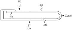
图1是根据一示例性实施例示出的电子设备的结构示意图。如图1所示,该电子设备具有正面110,背面120以及侧面130。其中,侧面130与正面110和背面120相连。电子设备还包括柔性显示屏200,柔性显示屏200的一端固定在电子设备的正面110,另一端由电子设备的侧面130延伸至电子设备的背面120。据此,柔性显示屏200在电子设备的正面110、侧面130和背面120连续分布。FIG. 1 is a schematic structural diagram of an electronic device according to an exemplary embodiment. As shown in FIG. 1 , the electronic device has a
该电子设备在使用时,具有拉伸形态和回缩形态两种使用形态。如图2所示,在拉伸形态下,柔性显示屏200位于电子设备背面120的部分由侧面130翻转至电子设备的正面110,增加电子设备正面110的显示屏尺寸。在回缩形态下,柔性显示屏200位于电子设备正面110的部分由侧面130翻转至电子设备的背面120,减少电子设备正面110的显示屏尺寸。When the electronic device is in use, it has two use forms: a stretched form and a retracted form. As shown in FIG. 2 , in the stretched state, the part of the
图2是根据另一示例性实施例示出的电子设备的结构示意图。如图2所示,柔性显示屏200的一部分设置在电子设备的内部,另一部分设置在电子设备的正面110。在拉伸形态下,将柔性显示屏200设置在电子设备内部的部分拉伸至电子设备外部,增加电子设备正面110的显示屏尺寸。在回缩形态下,将电子设备正面110上的柔性显示屏200的部分回缩至电子设备内,减少电子设备正面110的显示屏尺寸。FIG. 2 is a schematic structural diagram of an electronic device according to another exemplary embodiment. As shown in FIG. 2 , a part of the
基于上述电子设备,本公开实施例提供了一种显示屏伸缩驱动机构,该显示屏伸缩驱动机构用于拉伸或回缩柔性显示屏200,进而实现电子设备不通过使用形态的切换。Based on the above electronic device, an embodiment of the present disclosure provides a display screen telescopic drive mechanism, the display screen telescopic drive mechanism is used to stretch or retract the
图3是根据一示例性实施例示出的显示屏伸缩驱动机构的结构示意图。如图3所示,该显示屏伸缩驱动机构包括:壳体300、驱动组件400和活动组件500。FIG. 3 is a schematic structural diagram of a display screen telescopic drive mechanism according to an exemplary embodiment. As shown in FIG. 3 , the display screen telescopic drive mechanism includes: a
壳体300用于与柔性显示屏200的第一端210相连。可选地,壳体300为电子设备的中框。并且,结合图1和图2所示的两种情况,壳体300具有不同的实现方式。The
在一个示例中,参见图1和图3,壳体300包括相对设置的第一边310和第二边320,第一边310和第二边320之间具有间隔区域300a。驱动组件400设置在间隔区域300a内,并且,驱动组件400与第一边310和第二边320相连。In one example, referring to FIGS. 1 and 3 , the
在一个示例中,参见图2和图3,壳体300形成有安装腔300b,柔性显示屏200中靠近第一端210的部分设置在容纳腔310中,柔性显示屏200的其他部分由容纳腔310延伸至电子设备的正面110上。此时,驱动组件400在安装腔300b内,并与壳体300保持相对固定(例如通过连接件与壳体300固定连接)。In one example, referring to FIG. 2 and FIG. 3 , the
继续参见图3,驱动组件400包括驱动部410、活动部420和支架430。其中,驱动部410与壳体300相连。例如,支架430与壳体300相连,驱动部410安装在支架430上。活动部420与驱动部410传动连接,并且,活动部420可相对驱动部410移动。以此方式,在驱动部410的驱动作用下,活动部420相对壳体300具有远离或靠近的运动行程。Continuing to refer to FIG. 3 , the driving
可选地,图4是根据一示例性实施例示出的驱动组件400的结构示意图。如图4所示,驱动部410包括:驱动件411、减速件412和传动件413。Optionally, FIG. 4 is a schematic structural diagram of a
其中,驱动件411包括至少一个驱动马达411a,以及与驱动马达411a电性连接的电路板411b。通过电路板411b用于将驱动马达411a与控制组件(例如控制芯片)电性连接,以实现驱动马达411a可控设置。驱动马达411a可选为直流步进电机。此时,驱动马达411a将电脉冲信号转变为角位移或线位移。此时,通过脉冲信号控制驱动马达411a按设定的方向转动一个固定的角度,并通过控制脉冲个数来控制角位移量,从而达到准确定位的目的。同时,通过控制脉冲频率来控制驱动马达411a的转动速度和加速度,从而达到调速的目的,输入转动的扭力。The driving
减速件412与驱动件411连接,可选地,减速件412与驱动马达411a的输出轴固定连接。减速件412还与传动件413相连,用于以低于驱动件411直接输出的转速实现传动件413转动。可选地,减速件412包括相啮合的第一减速单元412a和第二减速单元412b。通过第一减速单元412a和第二减速单元412b实现两级减速,以将驱动件411的低扭矩转换成高扭矩。The
图5是根据一示例性实施例示出的减速件中第一减速单元的爆炸图。如图5所示,第一减速单元412a包括:固定件4121、以及安装在固定件4121中的马达齿4122和减速齿轮组合4123。FIG. 5 is an exploded view of a first speed reduction unit in a speed reduction member according to an exemplary embodiment. As shown in FIG. 5 , the
结合图4,固定件4121包括但不限于固齿圈,通过固齿圈形成了第一减速单元412a的外壳体。马达齿4122的一端直接与驱动马达411a固定连接,另一端设置有传动齿,与减速齿轮组合4123啮合。减速齿轮组件4123是第一减速单元412a的核心组成,用于实现转动调节的作用。在本公开实施例中,减速齿轮组件4123包括但不限于至少一个行星齿轮。并且,该减速齿轮组件4123还与第二减速单元412b连接。此外,在马达齿4122和驱动马达411a之间设置有衬套,在减速齿轮组件4123和第二减速单元412b之间设置有衬套。Referring to FIG. 4 , the fixing
采用这样的方式,驱动马达411带动马达齿4122转动,马达齿4122驱动减速齿轮组合4123转动,进而减速齿轮组件4123带动第二减速单元412b转动,进而驱动传动件413。In this way, the driving
继续参见图4,传动件413与减速件412相连,并用于传动连接活动部420。可选地,传动件413为与减速件412啮合的丝杆,且传动件413以可转动的方式与支架430连接。在这样的情况下,通过传动架413带动减速件412相对支架430转动。并且,此时活动部420套接在传动件413上,并与传动件413螺纹连接。此外,驱动组件400还包括与传动件413平行设置的导向部440,活动部420还套接在导向部440上。通过导向部440限定活动件420沿导向部440做线性运动,进而实现活动件420带动活动组件500做线性运动。Continuing to refer to FIG. 4 , the
继续参见图3,活动组件500与活驱动组件400中的活动部420相连。Continuing to refer to FIG. 3 , the
图6是根据一示例性实施例示出的显示屏伸缩驱动机构的局部剖视图。结合图6所示,在活动组件500上设置有插槽500a,活动部420插接在插槽500a中。据此,活动组件500与活动部420保持同步线性运动。FIG. 6 is a partial cross-sectional view of a display screen telescopic drive mechanism according to an exemplary embodiment. Referring to FIG. 6 , a
并且,活动组件500还与柔性显示屏200相连,例如与柔性显示屏200直接连接,或者通过其他机构连接。活动组件500用于受驱动组件400驱动带动柔性显示屏200的第二端220远离或靠近柔性显示屏200的第一端210。In addition, the
采用这样的方式,当活动组件500受驱动组件400驱动带动柔性显示屏200的第二端220远离柔性显示屏200的第一端210时,柔性显示屏200处于拉伸形态。当活动组件500受驱动组件400驱动带动柔性显示屏200的第二端220靠近柔性显示屏200的第一端210时,柔性显示屏200处于回缩形态。据此,通过该显示屏伸缩驱动机构实现柔性显示屏200的拉伸和回缩目的,进而切换电子设备的不同使用形态。In this way, when the
此外,在一个实施例中,显示屏伸缩驱动机构还包括距离检测组件。该距离检测组件包括发射件610和接收件620。其中,发射件610和接收件620中一个设置在壳体300上,另一个设置在活动组件500上。据此,通过距离检测组件能够检测距离壳体300与活动组件500之间的距离,以便于确定柔性显示屏200的伸缩情况。其中,距离检测组件包括但不限于光学距离检测组件(例如红外距离传感器)和磁场检测组件(例如霍尔传感器)。In addition, in one embodiment, the display screen telescopic drive mechanism further includes a distance detection component. The distance detection assembly includes a
在本公开实施例中,基于柔性显示屏200在电子设备中不同的设置方式,该显示屏伸缩驱动机构的具体结构有所差异,以下结合图1和图2进行详细说明。In the embodiment of the present disclosure, based on the different setting methods of the
<第一种方式><The first way>
在图1所示的电子设备中,壳体300与柔性显示屏200的第一端210固定连接。可选地,壳体300包括支撑部310,以及与支撑部310相连的侧边320。以此方式,侧边310形成了电子设备的外边缘,支撑部310位于电子设备内部,用于承载或安装电子设备内的功能模组。例如图1所示,支撑部310具有矩形板状结构,侧边320围绕支撑部310的三边设置。In the electronic device shown in FIG. 1 , the
图7a和图7b是根据不同示例性实施例示出的设置有该显示屏伸缩驱动机构的电子设备的剖视图。7a and 7b are cross-sectional views of an electronic device provided with the display screen telescopic drive mechanism according to different exemplary embodiments.
如图7a和图7b所示,壳体300与柔性显示屏200的第一端210固定连接。例如,第一端210通过屏幕压边条固定在壳体300的支撑部310上。As shown in FIGS. 7 a and 7 b , the
活动组件500抵接柔性显示屏200对应电子设备侧面130的部分。并且,活动组件500与柔性显示屏200的第二端220连接。例如,活动组件500直接与柔性显示屏200的第二端220相连。或者,电子设备还包括伸缩辅助机构。该伸缩辅助机构与活动组件500连接,并与柔性显示屏200的第二端220活动连接。在伸缩辅助机构中设置有弹性件,在第二端220远离第一端210的时候,弹性件拉伸,为第二端220施加回缩作用力。The
采用该可选方式显示屏的伸缩过程如下:The expansion and contraction process of the display screen using this optional method is as follows:
如图7a所示,驱动组件400驱动活动组件500向柔性显示屏200对应侧面130的部分施加向外伸展的作用力。此时,柔性显示屏200的第二端220向远离第一端210方向移动,以增加位于电子设备正面110上的柔性显示屏200的尺寸。As shown in FIG. 7 a , the
如图7b所示,驱动组件400驱动活动组件500向柔性显示屏200对应侧面130的部分施加向内回缩的作用力。此时,柔性显示屏200的第二端220向靠近第一端210的方向移动,以减少位于电子设备正面110上的柔性显示屏200的尺寸。As shown in FIG. 7b , the
图8是根据一示例性实施例示出的显示屏伸缩驱动机构的结构示意图。如图8所示,活动组件500包括用于抵接柔性显示屏200的弧形侧部510。通过该弧形侧部510抵接柔性显示屏200,一方面便于柔性显示屏200相对活动组件500滑动,另一方面保护柔性显示屏200的结构安全。FIG. 8 is a schematic structural diagram of a display screen telescopic drive mechanism according to an exemplary embodiment. As shown in FIG. 8 , the
进一步地,在弧形侧部510上设置有第一传动件511,第一传动件511与柔性显示屏200滚动连接。通过滚动连接进一步降低柔性显示屏200与活动组件500之间的摩擦力。可选地,第一传动件511为设置在弧形侧部510上的滚珠连接件,第一传动件511的滚珠直接接触柔性显示屏。其中,关于第一传动件511的数量不做具体限定,例如2个、3个、4个等。当弧形侧部510上设置有至少两个第一传动件511时,至少两个第一传动件511沿弧形侧部510的长度方向均匀分布。Further, a first transmission member 511 is provided on the arc-shaped
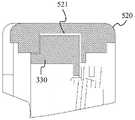
可选地,再次参见图3,壳体300还包括与第一边310和第二边320相连的导向件330。活动组件500包括设置在弧形侧部510上的连接部520。导向件330与连接部520活动连接,用于限位活动组件500沿导向件330移动。图9是根据另一示例性实施例示出的显示屏伸缩驱动机构的局部剖视图。结合图9,沿连接部520的长度方向设置有插槽521,导向件330卡接在插槽中,据此实现活动组件500和壳体300的活动连接。Optionally, referring again to FIG. 3 , the
<第二种方式><Second way>
在图2所示的电子设备中,壳体300形成有容纳腔310,柔性显示屏200的一部分设置在容纳腔310中,另一部分由容纳腔310延伸至电子设备的正面110上。并且,活动组件500与柔性显示屏200的第二端220连接。In the electronic device shown in FIG. 2 , the
采用该可选方式显示屏的伸缩过程如下:The expansion and contraction process of the display screen using this optional method is as follows:
驱动组件400驱动活动组件500带动柔性显示屏200的第二端220向远离第一端210的方向运动。此时,原先位于安装腔300b内的柔性显示屏200拉出至安装腔300b外,以增加位于电子设备正面110上的柔性显示屏200的尺寸。The
驱动组件400驱动活动组件500带动柔性显示屏200的第二端220向靠近第一段210的方向运动。此时,原先位于电子设备正面110上的柔性显示屏200回缩至安装腔300b内,以减少位于电子设备正面110上的柔性显示屏200的尺寸。The
基于上述提供的显示屏伸缩驱动机构,本公开实施例还提供了一种电子设备。该电子设备包括处理器、柔性显示屏,以及上述提供的显示屏伸缩驱动机构。其中,处理器与显示屏伸缩驱动机构的驱动马达的电路板电性连接,通过控制驱动马达实现显示屏在拉伸形态和回缩形态之间的切换。Based on the display screen telescopic drive mechanism provided above, an embodiment of the present disclosure further provides an electronic device. The electronic device includes a processor, a flexible display screen, and the display telescopic drive mechanism provided above. The processor is electrically connected to the circuit board of the drive motor of the display screen telescopic drive mechanism, and the display screen is switched between the stretched state and the retracted state by controlling the drive motor.
在拉伸形态下,电子设备正面110的显示屏尺寸较大。在回缩形态下,电子设备正面110的显示屏尺寸较小。以此方式,为电子设备提供了一种新型的形态切换方式,满足用户使用需求。In the stretched state, the size of the display screen on the
本领域技术人员在考虑说明书及实践这里公开的公开后,将容易想到本公开的其它实施方案。本公开旨在涵盖本公开的任何变型、用途或者适应性变化,这些变型、用途或者适应性变化遵循本公开的一般性原理并包括本公开未公开的本技术领域中的公知常识或惯用技术手段。说明书和实施例仅被视为示例性的,本公开的真正范围和精神由上述权利要求指出。Other embodiments of the present disclosure will readily occur to those skilled in the art upon consideration of the specification and practice of the disclosure disclosed herein. This disclosure is intended to cover any variations, uses, or adaptations of this disclosure that follow the general principles of this disclosure and include common general knowledge or techniques in the technical field not disclosed by this disclosure . The specification and examples are to be regarded as exemplary only, with the true scope and spirit of the disclosure being indicated by the following claims.
Claims (10)
Priority Applications (3)
| Application Number | Priority Date | Filing Date | Title |
|---|---|---|---|
| CN202011438597.XACN114596772B (en) | 2020-12-07 | 2020-12-07 | Display screen telescopic driving mechanism and electronic device |
| US17/328,756US11551585B2 (en) | 2020-12-07 | 2021-05-24 | Display-screen stretch and retraction driving mechanism and electronic apparatus |
| EP21176325.5AEP4009135A1 (en) | 2020-12-07 | 2021-05-27 | Display-screen stretch and retraction driving mechanism and electronic apparatus |
Applications Claiming Priority (1)
| Application Number | Priority Date | Filing Date | Title |
|---|---|---|---|
| CN202011438597.XACN114596772B (en) | 2020-12-07 | 2020-12-07 | Display screen telescopic driving mechanism and electronic device |
Publications (2)
| Publication Number | Publication Date |
|---|---|
| CN114596772Atrue CN114596772A (en) | 2022-06-07 |
| CN114596772B CN114596772B (en) | 2024-05-24 |
Family
ID=76159385
Family Applications (1)
| Application Number | Title | Priority Date | Filing Date |
|---|---|---|---|
| CN202011438597.XAActiveCN114596772B (en) | 2020-12-07 | 2020-12-07 | Display screen telescopic driving mechanism and electronic device |
Country Status (3)
| Country | Link |
|---|---|
| US (1) | US11551585B2 (en) |
| EP (1) | EP4009135A1 (en) |
| CN (1) | CN114596772B (en) |
Cited By (1)
| Publication number | Priority date | Publication date | Assignee | Title |
|---|---|---|---|---|
| CN114598759A (en)* | 2020-12-07 | 2022-06-07 | 北京小米移动软件有限公司 | Electronic equipment |
Families Citing this family (3)
| Publication number | Priority date | Publication date | Assignee | Title |
|---|---|---|---|---|
| EP4246501A4 (en)* | 2021-05-17 | 2024-07-10 | Samsung Electronics Co., Ltd. | ELECTRONIC DEVICE COMPRISING A FLEXIBLE DISPLAY DEVICE |
| CN115529776A (en)* | 2021-06-25 | 2022-12-27 | 北京小米移动软件有限公司 | A slide rail mechanism, telescopic screen structure and electronic equipment |
| EP4276577A4 (en)* | 2022-04-01 | 2024-08-21 | Samsung Electronics Co., Ltd. | Electronic device including flexible display |
Citations (13)
| Publication number | Priority date | Publication date | Assignee | Title |
|---|---|---|---|---|
| US20150153777A1 (en)* | 2013-12-03 | 2015-06-04 | Nvidia Corporation | Electronic device with both inflexible display screen and flexible display screen |
| CN209351130U (en)* | 2018-05-11 | 2019-09-06 | 青岛滨海学院 | A multifunctional blackboard |
| CN110493396A (en)* | 2019-08-12 | 2019-11-22 | 惠州Tcl移动通信有限公司 | A kind of electronic equipment |
| CN110572496A (en)* | 2019-09-23 | 2019-12-13 | 维沃移动通信有限公司 | Electronic equipment |
| CN210223370U (en)* | 2019-06-21 | 2020-03-31 | 深圳市柔宇科技有限公司 | Lifting mechanism, flexible screen display device and electronic device |
| CN111243440A (en)* | 2020-03-11 | 2020-06-05 | 昆山国显光电有限公司 | Flexible display device |
| CN111508374A (en)* | 2020-05-26 | 2020-08-07 | 武汉华星光电半导体显示技术有限公司 | Flexible display device |
| CN111510532A (en)* | 2020-04-27 | 2020-08-07 | 维沃移动通信有限公司 | Electronic equipment |
| US20200264660A1 (en)* | 2019-02-14 | 2020-08-20 | Lg Electronics Inc. | Mobile terminal |
| CN111587016A (en)* | 2020-05-29 | 2020-08-25 | 维沃移动通信有限公司 | Electronic equipment |
| CN111833748A (en)* | 2020-07-13 | 2020-10-27 | Oppo广东移动通信有限公司 | Flexible display device and electronic equipment |
| CN211857346U (en)* | 2020-05-29 | 2020-11-03 | 维沃移动通信有限公司 | Electronic device |
| CN112040033A (en)* | 2019-06-03 | 2020-12-04 | 北京小米移动软件有限公司 | a terminal |
Family Cites Families (16)
| Publication number | Priority date | Publication date | Assignee | Title |
|---|---|---|---|---|
| US8711566B2 (en)* | 2011-09-02 | 2014-04-29 | Microsoft Corporation | Expandable mobile device |
| TWI582640B (en)* | 2013-01-10 | 2017-05-11 | 黃海濤 | Hand-held electronic device having rolled-up screen and display method thereof |
| KR102269135B1 (en)* | 2014-10-06 | 2021-06-25 | 삼성디스플레이 주식회사 | Display apparatus |
| EP3239965A4 (en)* | 2014-12-25 | 2018-07-11 | Shenzhen Royole Technologies Co., Ltd. | Flexible display device |
| KR102468289B1 (en)* | 2016-05-30 | 2022-11-17 | 엘지디스플레이 주식회사 | Rollable display device |
| CN108230937B (en)* | 2018-03-26 | 2024-09-10 | 京东方科技集团股份有限公司 | Flexible display device |
| KR102609502B1 (en) | 2018-10-30 | 2023-12-04 | 삼성디스플레이 주식회사 | Display device |
| CN109257472B (en) | 2018-11-22 | 2024-03-22 | 江苏精研科技股份有限公司 | Telescopic device and mobile phone |
| WO2020166856A1 (en) | 2019-02-14 | 2020-08-20 | Lg Electronics Inc. | Mobile terminal |
| CN111831060B (en)* | 2019-04-19 | 2024-04-26 | 北京小米移动软件有限公司 | Mobile terminal, screen control method, device and storage medium |
| CN111831058A (en)* | 2019-04-19 | 2020-10-27 | 北京小米移动软件有限公司 | Mobile terminal, screen control method, device and storage medium |
| KR102859226B1 (en) | 2019-04-25 | 2025-09-12 | 엘지전자 주식회사 | Roll-slide mobile terminal |
| CN112087540B (en)* | 2019-06-14 | 2021-10-22 | 北京小米移动软件有限公司 | Folding device, display module and mobile terminal |
| CN112991928B (en)* | 2019-12-13 | 2022-08-16 | Oppo广东移动通信有限公司 | Electronic device with a detachable cover |
| CN113851042B (en)* | 2020-06-28 | 2023-06-02 | Oppo广东移动通信有限公司 | Electronic equipment |
| CN114598759A (en)* | 2020-12-07 | 2022-06-07 | 北京小米移动软件有限公司 | Electronic equipment |
- 2020
- 2020-12-07CNCN202011438597.XApatent/CN114596772B/enactiveActive
- 2021
- 2021-05-24USUS17/328,756patent/US11551585B2/enactiveActive
- 2021-05-27EPEP21176325.5Apatent/EP4009135A1/enactivePending
Patent Citations (13)
| Publication number | Priority date | Publication date | Assignee | Title |
|---|---|---|---|---|
| US20150153777A1 (en)* | 2013-12-03 | 2015-06-04 | Nvidia Corporation | Electronic device with both inflexible display screen and flexible display screen |
| CN209351130U (en)* | 2018-05-11 | 2019-09-06 | 青岛滨海学院 | A multifunctional blackboard |
| US20200264660A1 (en)* | 2019-02-14 | 2020-08-20 | Lg Electronics Inc. | Mobile terminal |
| CN112040033A (en)* | 2019-06-03 | 2020-12-04 | 北京小米移动软件有限公司 | a terminal |
| CN210223370U (en)* | 2019-06-21 | 2020-03-31 | 深圳市柔宇科技有限公司 | Lifting mechanism, flexible screen display device and electronic device |
| CN110493396A (en)* | 2019-08-12 | 2019-11-22 | 惠州Tcl移动通信有限公司 | A kind of electronic equipment |
| CN110572496A (en)* | 2019-09-23 | 2019-12-13 | 维沃移动通信有限公司 | Electronic equipment |
| CN111243440A (en)* | 2020-03-11 | 2020-06-05 | 昆山国显光电有限公司 | Flexible display device |
| CN111510532A (en)* | 2020-04-27 | 2020-08-07 | 维沃移动通信有限公司 | Electronic equipment |
| CN111508374A (en)* | 2020-05-26 | 2020-08-07 | 武汉华星光电半导体显示技术有限公司 | Flexible display device |
| CN211857346U (en)* | 2020-05-29 | 2020-11-03 | 维沃移动通信有限公司 | Electronic device |
| CN111587016A (en)* | 2020-05-29 | 2020-08-25 | 维沃移动通信有限公司 | Electronic equipment |
| CN111833748A (en)* | 2020-07-13 | 2020-10-27 | Oppo广东移动通信有限公司 | Flexible display device and electronic equipment |
Cited By (1)
| Publication number | Priority date | Publication date | Assignee | Title |
|---|---|---|---|---|
| CN114598759A (en)* | 2020-12-07 | 2022-06-07 | 北京小米移动软件有限公司 | Electronic equipment |
Also Published As
| Publication number | Publication date |
|---|---|
| US11551585B2 (en) | 2023-01-10 |
| EP4009135A1 (en) | 2022-06-08 |
| US20220180777A1 (en) | 2022-06-09 |
| CN114596772B (en) | 2024-05-24 |
Similar Documents
| Publication | Publication Date | Title |
|---|---|---|
| CN114596772A (en) | Display telescopic drive mechanism and electronic equipment | |
| JP7399908B2 (en) | Electronics | |
| CN109788683B (en) | Electronic device | |
| WO2020215376A1 (en) | Camera device, electronic apparatus, and method for using electronic apparatus | |
| WO2021129132A1 (en) | Electronic apparatus | |
| US20240357757A1 (en) | Electronic Device | |
| TW201447124A (en) | Biaxial pivoting mechanism and portable electronic device thereof | |
| WO2021139095A1 (en) | Camera module lifting device and electronic apparatus | |
| CN112398974A (en) | Camera module, terminal equipment and shooting method | |
| CN110471496A (en) | A kind of terminal device | |
| EP4123416A1 (en) | Flip function component and electronic device | |
| CN209120296U (en) | Camera module and electronic equipment | |
| WO2022089343A1 (en) | Electronic device | |
| CN113114805B (en) | Imaging device and electronic apparatus | |
| CN213342411U (en) | Camera structure and terminal equipment | |
| WO2021127917A1 (en) | Photographing device, electronic apparatus, and method of using electronic apparatus | |
| CN113163040B (en) | Electronic device | |
| CN109995900B (en) | Functional component, electronic device and control method thereof | |
| CN114554033A (en) | Camera structure and terminal equipment | |
| CN112020278A (en) | heat sink | |
| CN110650233A (en) | Electronic equipment | |
| CN110324056B (en) | Electronic device and control method of electronic device | |
| WO2021128241A1 (en) | Photographing device, electronic apparatus, and method of using electronic apparatus | |
| CN113132587B (en) | Camera module and terminal equipment | |
| CN113079277B (en) | Terminal equipment, camera module and shooting method |
Legal Events
| Date | Code | Title | Description |
|---|---|---|---|
| PB01 | Publication | ||
| PB01 | Publication | ||
| SE01 | Entry into force of request for substantive examination | ||
| SE01 | Entry into force of request for substantive examination | ||
| GR01 | Patent grant | ||
| GR01 | Patent grant |