CN114592796A - A PDC bit suitable for tight mudstone formations - Google Patents
A PDC bit suitable for tight mudstone formationsDownload PDFInfo
- Publication number
- CN114592796A CN114592796ACN202210500029.0ACN202210500029ACN114592796ACN 114592796 ACN114592796 ACN 114592796ACN 202210500029 ACN202210500029 ACN 202210500029ACN 114592796 ACN114592796 ACN 114592796A
- Authority
- CN
- China
- Prior art keywords
- seat
- connecting rod
- cutting unit
- blade
- groove
- Prior art date
- Legal status (The legal status is an assumption and is not a legal conclusion. Google has not performed a legal analysis and makes no representation as to the accuracy of the status listed.)
- Granted
Links
- 230000015572biosynthetic processEffects0.000titleclaimsabstractdescription32
- 238000005755formation reactionMethods0.000titleclaimsabstractdescription32
- 230000007246mechanismEffects0.000claimsabstractdescription35
- 239000002131composite materialSubstances0.000claimsabstractdescription6
- 229910003460diamondInorganic materials0.000claimsabstractdescription6
- 239000010432diamondSubstances0.000claimsabstractdescription6
- 239000007788liquidSubstances0.000claimsdescription72
- 238000000926separation methodMethods0.000claimsdescription36
- 239000011435rockSubstances0.000claimsdescription11
- XLYOFNOQVPJJNP-UHFFFAOYSA-NwaterSubstancesOXLYOFNOQVPJJNP-UHFFFAOYSA-N0.000claimsdescription5
- 230000001360synchronised effectEffects0.000claimsdescription4
- 230000000903blocking effectEffects0.000claimsdescription3
- 230000036346tooth eruptionEffects0.000claimsdescription3
- 230000007704transitionEffects0.000claimsdescription3
- 239000007921spraySubstances0.000claims1
- 238000005553drillingMethods0.000abstractdescription16
- 238000000034methodMethods0.000abstractdescription6
- 230000008569processEffects0.000abstractdescription5
- 230000009918complex formationEffects0.000abstractdescription4
- 230000000694effectsEffects0.000description3
- 238000010586diagramMethods0.000description2
- 230000009286beneficial effectEffects0.000description1
- 230000008859changeEffects0.000description1
- 238000001514detection methodMethods0.000description1
- 230000004048modificationEffects0.000description1
- 238000012986modificationMethods0.000description1
- 230000000149penetrating effectEffects0.000description1
- 239000013049sedimentSubstances0.000description1
Images


Classifications
- E—FIXED CONSTRUCTIONS
- E21—EARTH OR ROCK DRILLING; MINING
- E21B—EARTH OR ROCK DRILLING; OBTAINING OIL, GAS, WATER, SOLUBLE OR MELTABLE MATERIALS OR A SLURRY OF MINERALS FROM WELLS
- E21B10/00—Drill bits
- E21B10/26—Drill bits with leading portion, i.e. drill bits with a pilot cutter; Drill bits for enlarging the borehole, e.g. reamers
- E—FIXED CONSTRUCTIONS
- E21—EARTH OR ROCK DRILLING; MINING
- E21B—EARTH OR ROCK DRILLING; OBTAINING OIL, GAS, WATER, SOLUBLE OR MELTABLE MATERIALS OR A SLURRY OF MINERALS FROM WELLS
- E21B10/00—Drill bits
- E21B10/60—Drill bits characterised by conduits or nozzles for drilling fluids
- E21B10/602—Drill bits characterised by conduits or nozzles for drilling fluids the bit being a rotary drag type bit with blades
Landscapes
- Engineering & Computer Science (AREA)
- Life Sciences & Earth Sciences (AREA)
- Geology (AREA)
- Mining & Mineral Resources (AREA)
- Mechanical Engineering (AREA)
- Physics & Mathematics (AREA)
- Environmental & Geological Engineering (AREA)
- Fluid Mechanics (AREA)
- General Life Sciences & Earth Sciences (AREA)
- Geochemistry & Mineralogy (AREA)
- Earth Drilling (AREA)
Abstract
Translated fromChinese
Description
Translated fromChinese技术领域technical field
本发明属于钻井设备领域,具体涉及一种适用于致密泥岩地层的PDC钻头。The invention belongs to the field of drilling equipment, in particular to a PDC drill bit suitable for tight mudstone formations.
背景技术Background technique
PDC钻头也称聚晶金刚石复合钻头,一般包括钻头本体,以及镶嵌在钻头本体端部的聚晶金刚石复合片,聚晶精钢石复合片是以硬质合金为基底,且表面具有聚晶金刚石涂层的切削部件。传统PDC钻头一般为一体式结构,各切削齿的相对位置一般是固定的,然而在实际使用过程中发现,针对不同地质层,钻头的切削效率受切削齿分布情况影响较大,例如在相对蓬松的上层岩层中,采用较小的切削面积能够明显提高钻进速度,采用较大的切削面积则会导致钻进速度降低且容易在钻头端部出现泥包;而对于致密的泥岩地层,采用较大的切削面积则更有利与钻头的稳定进给。由于现有技术中的钻头均为一体式结构,因此在面对不同岩层时需要反复更换钻头,严重影响钻井效率。PDC drill bits are also called polycrystalline diamond composite drill bits, which generally include a drill bit body and a polycrystalline diamond composite sheet embedded in the end of the drill bit body. Coated cutting parts. Traditional PDC bits are generally of one-piece structure, and the relative position of each cutter is generally fixed. However, in actual use, it is found that for different geological layers, the cutting efficiency of the bit is greatly affected by the distribution of cutters. In the upper rock strata, using a smaller cutting area can significantly increase the drilling speed, while using a larger cutting area will lead to a decrease in the drilling speed and easy occurrence of mud bags at the end of the drill bit; while for tight mudstone strata, using a relatively small cutting area will reduce the drilling speed. A large cutting area is more beneficial to the stable feed of the drill. Since the drill bits in the prior art are all of one-piece structure, the drill bits need to be replaced repeatedly when facing different rock formations, which seriously affects the drilling efficiency.
发明内容SUMMARY OF THE INVENTION
鉴于以上所述现有技术的缺点,本发明的目的是提供一种能够提高钻井效率的适用于致密泥岩地层的PDC钻头。In view of the above-mentioned shortcomings of the prior art, the purpose of the present invention is to provide a PDC drill bit suitable for tight mudstone formations which can improve drilling efficiency.
为实现上述目的及其它相关目的,本发明提供了以下技术方案:For achieving the above-mentioned purpose and other related purposes, the present invention provides the following technical solutions:
一种适用于致密泥岩地层的PDC钻头,包括:A PDC bit suitable for tight mudstone formations, comprising:
外切削单元,包括外刀座,所述外刀座的中心设有贯穿所述外刀座的中心孔,所述外刀座的冠部设有外刀翼,所述外刀翼自所述中心孔的边缘延伸至所述外刀座的侧面,所述外刀翼沿所述外刀座的周向间隔设置多个;The outer cutting unit includes an outer blade holder, the center of the outer blade holder is provided with a central hole passing through the outer blade holder, the crown of the outer blade holder is provided with an outer blade wing, and the outer blade blade extends from the The edge of the central hole extends to the side surface of the outer knife seat, and a plurality of the outer knife wings are arranged at intervals along the circumferential direction of the outer knife seat;
内切削单元,包括内刀座,所述内刀座的冠部设有内刀翼,所述内刀翼仅分布于所述内刀座的端面,所述内刀翼沿所述内刀座的周向间隔设置多个;所述内刀座沿轴向活动设置于所述外刀座的中心孔内,以使所述内切削单元和所述外切削单元能够在以下两工位间切换:工位一,所述内刀翼相对于所述外刀翼沿轴向凸伸出预设距离;以及工位二,所述内刀翼与所述外刀翼的冠部平齐;所述内刀座与所述外刀座沿周向同步转动连接;The inner cutting unit includes an inner knife seat, the crown of the inner knife seat is provided with an inner knife wing, the inner knife wing is only distributed on the end face of the inner knife seat, and the inner knife wing is along the inner knife seat. The inner tool seat is movably arranged in the center hole of the outer tool seat in the axial direction, so that the inner cutting unit and the outer cutting unit can be switched between the following two stations : Station 1, the inner blade protrudes out a preset distance in the axial direction relative to the outer blade; and
连接杆,所述连接杆的一端设有用于连接钻杆的连接部,另一端与所述内刀座连接,以驱动所述内刀座沿轴向进给以及沿周向转动;a connecting rod, one end of the connecting rod is provided with a connecting part for connecting the drill rod, and the other end is connected with the inner tool seat, so as to drive the inner tool seat to feed in the axial direction and rotate in the circumferential direction;
锁止机构,设置于所述内刀座与所述外刀座之间,所述锁止机构被装配为具有锁止工位和解锁工位,当所述锁止机构位于锁止工位时,能够将处于所述工位二的所述外切削单元和所述内切削单元保持在所述工位二,以使所述外切削单元能够在工位二状态下与所述内切选单元同步进给;当所述锁止机构位于解锁工位时,所述外切削单元能够沿轴向相对于内切削单元自由活动,以使所述内切削单元进给时,所述外切削单元能够在岩层的阻挡下切换至所述工位一,并保持在所述工位一;a locking mechanism, arranged between the inner tool seat and the outer tool seat, the locking mechanism is assembled to have a locking station and an unlocking station, when the locking mechanism is located at the locking station , the outer cutting unit and the inner cutting unit in the second station can be kept in the second station, so that the outer cutting unit can be in the second station state with the inner cutting unit Synchronous feeding; when the locking mechanism is at the unlocking position, the outer cutting unit can move freely relative to the inner cutting unit in the axial direction, so that when the inner cutting unit feeds, the outer cutting unit can Switch to the station one under the blocking of the rock formation, and keep it at the station one;
所述外刀翼和所述内刀翼上设有金刚石复合切削齿。The outer blade and the inner blade are provided with diamond composite cutting teeth.
在本发明的一可选实施例中,所述内刀座上远离所述内刀翼的一端设有盲孔,所述连接杆插装于所述盲孔内;所述锁止机构包括活动设置于所述内刀座侧壁上的滚珠,以及设置于所述外刀座内壁的环槽,当所述内切削单元和所述外切削单元处于所述工位二时,所述滚珠与所述环槽对齐,所述内刀座的侧壁上开设有贯穿该侧壁设置的径向孔,所述滚珠沿所述内刀座的径向活动设置于所述径向孔内,所述滚珠的直径大于所述内刀座侧壁的厚度,所述连接杆上与所述滚珠对应位置处设有凹槽,所述凹槽的底面与所述连接杆的外壁之间平滑过渡,所述连接杆在预设角度范围内与所述内刀座转动配合,使所述连接杆和所述内刀座能够在第一角度区间和第二角度区间之间进行切换,当所述连接杆与所述内刀座位于第一角度区间时,所述滚珠与所述凹槽相对,此时所述滚珠内侧能够部分收容于所述凹槽内,以使所述滚珠外侧避开所述环槽,此时锁止机构处于所述解锁工位;当所述连接杆与所述内刀座位于第二角度区间时,所述凹槽与所述滚珠沿周向相互错开,以使所述滚珠被所述连接杆挤推至所述环槽内,此时所述锁止机构处于所述锁止工位;当所述连接杆相对于所述内刀座沿第一方向转动时,实现两者从第一角度区间到第二角度区间的切换,所述第一方向是钻头的切削方向。In an optional embodiment of the present invention, a blind hole is provided on an end of the inner knife seat away from the inner knife wing, and the connecting rod is inserted into the blind hole; the locking mechanism includes a movable The ball is arranged on the side wall of the inner tool seat, and the annular groove is arranged on the inner wall of the outer tool seat. When the inner cutting unit and the outer cutting unit are in the second station, the ball and the outer cutting unit are in the second position. The annular grooves are aligned, the side wall of the inner tool seat is provided with a radial hole arranged through the side wall, and the ball is movably arranged in the radial hole along the radial direction of the inner tool seat, so The diameter of the ball is larger than the thickness of the side wall of the inner tool seat, the connecting rod is provided with a groove at the position corresponding to the ball, and the bottom surface of the groove and the outer wall of the connecting rod smoothly transition. The connecting rod is rotatably matched with the inner tool seat within a preset angle range, so that the connecting rod and the inner tool seat can be switched between the first angle interval and the second angle interval. When the rod and the inner cutter seat are located in the first angle section, the ball is opposite to the groove, and the inner side of the ball can be partially accommodated in the groove, so that the outer side of the ball avoids the ring groove, the locking mechanism is in the unlocking position at this time; when the connecting rod and the inner tool seat are located in the second angle range, the groove and the ball are staggered from each other in the circumferential direction, so that all the The ball is pushed into the ring groove by the connecting rod, and the locking mechanism is in the locking position at this time; when the connecting rod rotates in the first direction relative to the inner tool seat, The switching of the two from the first angle interval to the second angle interval is realized, and the first direction is the cutting direction of the drill bit.
在本发明的一可选实施例中,所述连接杆的外壁上设有凸齿,所述内刀座的内壁上设有与所述凸齿配合的第一弧形槽和第二弧形槽,所述第一弧形槽和第二弧形槽沿所述内刀座的轴向间隔设置,且两者之间通过一轴向槽连通,所述连接杆沿轴向与所述内刀座活动连接,以使所述凸齿在所述第一弧形槽和所述第二弧形槽之间进行切换,当所述凸齿位于所述第一弧形槽内时,所述连接杆能够在所述第一角度区间和所述第二角度区间之间活动,当所述凸齿位于所述第二弧形槽内时,所述连接杆仅能在所述第一角度区间内活动;当所述连接杆沿第一直线方向相对于所述内刀座运动时,能够使所述凸齿从所述第一弧形槽移动至所述第二弧形槽,所述第一直线方向是钻头的进给方向。In an optional embodiment of the present invention, the outer wall of the connecting rod is provided with protruding teeth, and the inner wall of the inner tool seat is provided with a first arc-shaped groove and a second arc-shaped groove that cooperate with the protruding teeth The first arc-shaped groove and the second arc-shaped groove are arranged at intervals along the axial direction of the inner tool seat, and are communicated with each other through an axial groove, and the connecting rod is axially connected to the inner tool seat. The tool seat is movably connected, so that the protruding teeth are switched between the first arc-shaped groove and the second arc-shaped groove, and when the protruding teeth are located in the first arc-shaped groove, the The connecting rod can move between the first angle section and the second angle section, and when the protruding teeth are located in the second arc groove, the connecting rod can only move in the first angle section Internal movement; when the connecting rod moves relative to the inner tool seat along the first linear direction, the protruding teeth can be moved from the first arc-shaped groove to the second arc-shaped groove, the The first linear direction is the feed direction of the drill.
在本发明的一可选实施例中,所述连接杆内部设有主水道,所述外刀座的内壁与所述连接杆外壁之间形成有第一分液腔,所述连接杆端部与所述内刀座之间形成有第二分液腔,所述连接杆侧壁上设有分别连通第一分液腔和第二分液腔的第一通孔和第二通孔;所述外刀座内部设有第一流道,所述第一流道的进液口与所述第一分液腔连通,所述第一流道的出液口形成于所述外刀座的冠部,且该出液口位于相邻两外刀翼之间;所述内刀座内部设有第二流道,所述第二流道的进液口与所述第二分液腔连通,所述第二流道的出液口形成于所述内刀座的端部,且该出液口位于相邻两个所述内刀翼之间。In an optional embodiment of the present invention, the connecting rod is internally provided with a main water channel, a first liquid separation chamber is formed between the inner wall of the outer knife holder and the outer wall of the connecting rod, and the end of the connecting rod is A second liquid-separating cavity is formed between it and the inner knife seat, and a first through hole and a second through-hole respectively communicating with the first and second liquid-separating cavity are provided on the side wall of the connecting rod; A first flow channel is arranged inside the outer knife seat, the liquid inlet of the first flow channel is communicated with the first liquid separation chamber, and the liquid outlet of the first flow channel is formed on the crown of the outer knife seat, And the liquid outlet is located between two adjacent outer knife wings; the inner knife seat is provided with a second flow channel, the liquid inlet of the second flow channel is communicated with the second liquid separation cavity, and the The liquid outlet of the second flow channel is formed at the end of the inner blade seat, and the liquid outlet is located between two adjacent inner blade wings.
在本发明的一可选实施例中,所述连接杆上形成有一凸环,所述外刀座内壁上形成有第一台阶部和第二台阶部,所述第一台阶部的内环面与所述连接杆的外壁贴合,所述第二台阶部的内环面与所述连接杆的外壁间隔设置,所述第一台阶部和第二台阶部相对于所述凸环位于靠近所述外刀座冠部的一侧,所述凸环、外刀座内壁、第一台阶部和第二台阶部共同围合成所述第一分液腔,当所述第一分液腔内充入液体时能够对所述外刀座产生第一直线方向的推力。In an optional embodiment of the present invention, a convex ring is formed on the connecting rod, a first step portion and a second step portion are formed on the inner wall of the outer tool holder, and the inner ring surface of the first step portion is formed Fitted with the outer wall of the connecting rod, the inner ring surface of the second step portion is spaced apart from the outer wall of the connecting rod, and the first step portion and the second step portion are located close to each other relative to the convex ring. On one side of the crown portion of the outer knife seat, the convex ring, the inner wall of the outer knife seat, the first step portion and the second step portion together form the first liquid separation chamber, and when the first liquid separation chamber is filled with When liquid is injected, a thrust in the first linear direction can be generated on the outer cutter seat.
在本发明的一可选实施例中,所述第一流道的进液口形成与所述第二台阶部的内环面上。In an optional embodiment of the present invention, the liquid inlet of the first flow channel is formed on the inner annular surface of the second step portion.
在本发明的一可选实施例中,所述连接杆与所述内刀座之间设有闭合机构,所述闭合机构被装配为当所述连接杆与所述内刀座处于第一相对预设角度时,能够使所述主流道与所述第二分液腔之间的水路断开,所述第一相对预设角度位于所述第一角度区间内,且当所述连接杆与所述内刀座处于第一角度区间和第二角度区间内的其它相对角度时,能够使所述主流道与所述第二分液腔之间的水路连通。In an optional embodiment of the present invention, a closing mechanism is provided between the connecting rod and the inner knife seat, and the closing mechanism is assembled so that when the connecting rod and the inner knife seat are in a first opposite position When the angle is preset, the water path between the main channel and the second liquid separation chamber can be disconnected, the first relative preset angle is located in the first angle range, and when the connecting rod is connected to the When the inner cutter seat is at other relative angles within the first angle section and the second angle section, the water channel between the main flow channel and the second liquid separation chamber can be communicated.
在本发明的一可选实施例中,所述闭合机构包括所述内刀座的内壁上开设的轴向条槽,当所述连接杆与所述内刀座处于第一角度区间和第二角度区间内除所述第一相对预设角度以外的其它相对角度时,所述第二通孔与所述轴向条槽相对,此时第二通孔通过所述轴向条槽与所述第二分液腔连通;当所述连接杆与所述内刀座处于所述第一相对预设角度时,所述第二通孔与所述轴向条槽错开,此时第二通孔与所述第二分液腔断开。In an optional embodiment of the present invention, the closing mechanism includes an axial slot opened on the inner wall of the inner tool seat, when the connecting rod and the inner tool seat are in the first angle range and the second angle At other relative angles other than the first relative preset angle within the angle interval, the second through hole is opposite to the axial slot, and at this time, the second through hole passes through the axial slot and the The second liquid separation chamber is communicated; when the connecting rod and the inner cutter seat are at the first relative preset angle, the second through hole and the axial groove are staggered, and at this time the second through hole Disconnected from the second dispensing chamber.
在本发明的一可选实施例中,所述内刀座上自所述内刀翼的外端向所述内刀座的侧壁延伸形成有条形键,所述外刀座的内壁上形成有与所述条形键配合的键槽。In an optional embodiment of the present invention, a bar-shaped key is formed on the inner knife seat extending from the outer end of the inner knife wing to the side wall of the inner knife seat, and the inner wall of the outer knife seat is formed with a bar key. A keyway is formed to cooperate with the bar key.
在本发明的一可选实施例中,所述外刀翼的数量多于所述内刀翼的数量,且每个内刀翼都对应有一个与之沿径向对齐的外刀翼,这些与内刀翼对齐的外刀翼的内端设有辅助喷液口,所述辅助喷液口朝向所述条形键的外壁设置,所述辅助喷液口与所述第一流道连通。In an optional embodiment of the present invention, the number of the outer blades is greater than the number of the inner blades, and each inner blade corresponds to an outer blade aligned with it in the radial direction. The inner end of the outer blade that is aligned with the inner blade is provided with an auxiliary liquid jetting port, the auxiliary liquid jetting port is disposed toward the outer wall of the bar key, and the auxiliary liquid jetting port is communicated with the first flow channel.
本发明的技术效果在于:本发明采用具有活动部件的组合式钻头,其中外切削单元能够相对于内切削单元沿周向活动,并通过锁止机构实现两切削单元之间的锁止和释放,当切削蓬松地层时,内切削单元作为领眼钻头凸伸在外切削单元前方,而外切削单元作为扩孔钻头对内切削单元周围区域进行扩孔,提升了钻头的整体钻进能力,此时内刀翼与外刀翼之间具有较大间隙,能够避免钻头前端出现泥包;当切削致密泥岩地层时,内切削单元与外切削单元能够保持平齐,从而分散切削应力,确保钻进过程稳定,避免崩刃。本发明能够在两种工位之间来回切换,以便适应软硬交错的复杂地层环境。The technical effect of the present invention is that: the present invention adopts a combined drill bit with movable parts, wherein the outer cutting unit can move in the circumferential direction relative to the inner cutting unit, and the locking and releasing between the two cutting units are realized by the locking mechanism, When cutting fluffy formations, the inner cutting unit acts as a pilot bit and protrudes in front of the outer cutting unit, while the outer cutting unit acts as a reaming bit to ream the area around the inner cutting unit, improving the overall drilling capacity of the bit. There is a large gap between the blade and the outer blade, which can avoid the mud bag at the front end of the drill bit; when cutting tight mudstone formations, the inner cutting unit and the outer cutting unit can be kept flush, thereby dispersing the cutting stress and ensuring the stability of the drilling process , to avoid chipping. The invention can switch back and forth between the two working stations, so as to adapt to the complex formation environment where the soft and hard are interlaced.
附图说明Description of drawings
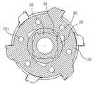
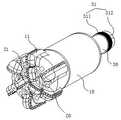
图1是本发明的实施例所提供的PDC钻头位于工位一时的立体图;1 is a perspective view of a PDC drill bit provided by an embodiment of the present invention when it is located at station one;
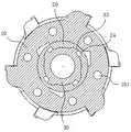
图2是本发明的实施例所提供的PDC钻头位于工位一时的主视图;2 is a front view of the PDC drill bit provided by an embodiment of the present invention when it is located at station one;
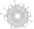
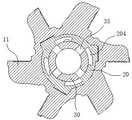
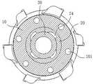
图3是本发明的实施例所提供的PDC钻头的端面视图;3 is an end view of a PDC drill bit provided by an embodiment of the present invention;
图4是图3的A-A剖视图;Fig. 4 is the A-A sectional view of Fig. 3;
图5是图4的B1-B1剖视图;Fig. 5 is B1-B1 sectional view of Fig. 4;
图6是图4的C1-C1剖视图;Fig. 6 is C1-C1 sectional view of Fig. 4;
图7是图4的D1-D1剖视图;Fig. 7 is D1-D1 sectional view of Fig. 4;
图8是图4的E1-E1剖视图;Fig. 8 is the E1-E1 sectional view of Fig. 4;
图9是本发明的实施例所提供的PDC钻头中间状态的剖视图,剖切位置与图5一致;9 is a cross-sectional view of the intermediate state of the PDC drill bit provided by the embodiment of the present invention, and the cutting position is the same as that of FIG. 5;
图10是本发明的实施例所提供的PDC钻头中间状态的剖视图,剖切位置与图6一致;10 is a cross-sectional view of the intermediate state of the PDC drill bit provided by the embodiment of the present invention, and the cutting position is the same as that of FIG. 6;
图11是本发明的实施例所提供的PDC钻头中间状态的剖视图,剖切位置与图7一致;11 is a cross-sectional view of the intermediate state of the PDC drill bit provided by the embodiment of the present invention, and the cutting position is the same as that of FIG. 7;
图12是本发明的实施例所提供的PDC钻头中间状态的剖视图,剖切位置与图8一致;12 is a cross-sectional view of the intermediate state of the PDC drill bit provided by the embodiment of the present invention, and the cutting position is the same as that of FIG. 8;
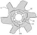
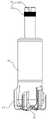
图13是本发明的实施例所提供的PDC钻头位于工位二时的立体图;13 is a perspective view of the PDC drill bit provided by the embodiment of the present invention when it is located at the second station;
图14是本发明的实施例所提供的PDC钻头位于工位二时的主视图;14 is a front view of the PDC drill bit provided by the embodiment of the present invention when it is located at the second station;
图15是本发明的实施例所提供的PDC钻头位于工位二时的剖视图;15 is a cross-sectional view of the PDC drill bit provided by the embodiment of the present invention when it is located at the second station;
图16是图15的B2-B2剖视图;Fig. 16 is the B2-B2 sectional view of Fig. 15;
图17是图15的C2-C2剖视图;Fig. 17 is the C2-C2 sectional view of Fig. 15;
图18是图15的D2-D2剖视图;Fig. 18 is the D2-D2 sectional view of Fig. 15;
图19是图15的E2-E2剖视图;Fig. 19 is the E2-E2 sectional view of Fig. 15;
图20是本发明的实施例所提供的PDC钻头的爆炸图,图中外切削单元和内切削单元为半剖状态;20 is an exploded view of a PDC drill bit provided by an embodiment of the present invention, in which the outer cutting unit and the inner cutting unit are in a half-section state;
各附图标记含义如下:10、外刀座;11、外刀翼;101、第一流道;102、辅助喷液口;103、第一分液腔;12、环槽;13、第一台阶部;14、第二台阶部;20、内刀座;21、内刀翼;201、第二流道;202、条形键;203、第二分液腔;204、轴向条槽;22、滚珠;23、第一弧形槽;24、第二弧形槽;25、轴向槽;30、连接杆;301、主水道;31、连接部;311、外螺纹;312、花键槽;32、凹槽;33、凸齿;34、第一通孔;35、第二通孔;36、凸环。The meanings of the reference symbols are as follows: 10, outer knife seat; 11, outer knife wing; 101, first flow channel; 102, auxiliary liquid ejection port; 103, first liquid separation chamber; 12, ring groove; 13, first step part; 14, the second step part; 20, the inner knife seat; 21, the inner knife wing; 201, the second flow channel; 202, the bar key; 203, the second liquid separation chamber; 204, the axial groove; 22 , ball; 23, first arc groove; 24, second arc groove; 25, axial groove; 30, connecting rod; 301, main water channel; 31, connecting part; 311, external thread; 312, spline groove; 32, groove; 33, convex teeth; 34, first through hole; 35, second through hole; 36, convex ring.
具体实施方式Detailed ways
以下通过特定的具体实例说明本发明的实施方式,本领域技术人员可由本说明书所揭露的内容轻易地了解本发明的其他优点与功效。本发明还可以通过另外不同的具体实施方式加以实施或应用,本说明书中的各项细节也可以基于不同观点与应用,在没有背离本发明的精神下进行各种修饰或改变。需说明的是,在不冲突的情况下,以下实施例及实施例中的特征可以相互组合。The embodiments of the present invention are described below through specific specific examples, and those skilled in the art can easily understand other advantages and effects of the present invention from the contents disclosed in this specification. The present invention can also be implemented or applied through other different specific embodiments, and various details in this specification can also be modified or changed based on different viewpoints and applications without departing from the spirit of the present invention. It should be noted that the following embodiments and features in the embodiments may be combined with each other under the condition of no conflict.
需要说明的是,以下实施例中所提供的图示仅以示意方式说明本发明的基本构想,遂图示中仅显示与本发明中有关的组件而非按照实际实施时的组件数目、形状及尺寸绘制,其实际实施时各组件的型态、数量及比例可为一种随意的改变,且其组件布局型态也可能更为复杂。It should be noted that the diagrams provided in the following embodiments are only used to illustrate the basic concept of the present invention in a schematic way, so the diagrams only show the components related to the present invention rather than the number, shape and For dimension drawing, the type, quantity and proportion of each component can be changed at will in actual implementation, and the component layout may also be more complicated.
请参阅图1-20所示,一种适用于致密泥岩地层的PDC钻头,包括:See Figure 1-20, a PDC bit suitable for tight mudstone formations, including:
外切削单元,包括外刀座10,所述外刀座10的中心设有贯穿所述外刀座10的中心孔,所述外刀座10的冠部设有外刀翼11,所述外刀翼11自所述中心孔的边缘延伸至所述外刀座10的侧面,所述外刀翼11沿所述外刀座10的周向间隔设置多个;The outer cutting unit includes an
内切削单元,包括内刀座20,所述内刀座20的冠部设有内刀翼21,所述内刀翼21仅分布于所述内刀座20的端面,所述内刀翼21沿所述内刀座20的周向间隔设置多个;所述内刀座20沿轴向活动设置于所述外刀座10的中心孔内,以使所述内切削单元和所述外切削单元能够在以下两工位间切换:工位一,所述内刀翼21相对于所述外刀翼11沿轴向凸伸出预设距离;以及工位二,所述内刀翼21与所述外刀翼11的冠部平齐,所述冠部是指钻头进给方向的前端;所述内刀座20与所述外刀座10沿周向同步转动连接;The inner cutting unit includes an
连接杆30,所述连接杆30的一端设有用于连接钻杆的连接部31,另一端与所述内刀座20连接,以驱动所述内刀座20沿轴向进给以及沿周向转动;A connecting
锁止机构,设置于所述内刀座20与所述外刀座10之间,所述锁止机构被装配为具有锁止工位和解锁工位,当所述锁止机构位于锁止工位时,能够将处于所述工位二的所述外切削单元和所述内切削单元保持在所述工位二,以使所述外切削单元能够在工位二状态下与所述内切选单元同步进给;当所述锁止机构位于解锁工位时,所述外切削单元能够沿轴向相对于内切削单元自由活动,以使所述内切削单元进给时,所述外切削单元能够在岩层的阻挡下切换至所述工位一,并保持在所述工位一;The locking mechanism is arranged between the
所述外刀翼11和所述内刀翼21上设有金刚石复合切削齿40。The
本发明采用具有活动部件的组合式钻头,其中外切削单元能够相对于内切削单元沿周向活动,并通过锁止机构实现两切削单元之间的锁止和释放,当切削蓬松地层时,内切削单元作为领眼钻头凸伸在外切削单元前方,而外切削单元作为扩孔钻头对内切削单元周围区域进行扩孔,提升了钻头的整体钻进能力,此时内刀翼21与外刀翼11之间具有较大间隙,能够避免钻头前端出现泥包;当切削致密泥岩地层时,内切削单元与外切削单元能够保持平齐,从而分散切削应力,确保钻进过程稳定,避免崩刃。本发明能够在两种工位之间来回切换,以便适应软硬交错的复杂地层环境。The present invention adopts a combined drill bit with movable parts, wherein the outer cutting unit can move in the circumferential direction relative to the inner cutting unit, and the locking and releasing between the two cutting units are realized through the locking mechanism. The cutting unit acts as a pilot bit and protrudes in front of the outer cutting unit, and the outer cutting unit acts as a reaming bit to ream the area around the inner cutting unit, which improves the overall drilling capacity of the drill bit. At this time, the
如图4、7、11、15、18、20所示,在一具体实施例中,所述内刀座20上远离所述内刀翼21的一端设有盲孔,所述连接杆30插装于所述盲孔内;所述锁止机构包括活动设置于所述内刀座20侧壁上的滚珠22,以及设置于所述外刀座10内壁的环槽12,当所述内切削单元和所述外切削单元处于所述工位二时,所述滚珠22与所述环槽12对齐,所述内刀座20的侧壁上开设有贯穿该侧壁设置的径向孔,所述滚珠22沿所述内刀座20的径向活动设置于所述径向孔内,所述滚珠22的直径大于所述内刀座20侧壁的厚度,所述连接杆30上与所述滚珠22对应位置处设有凹槽32,所述凹槽32的底面与所述连接杆30的外壁之间平滑过渡,所述连接杆30在预设角度范围内与所述内刀座20转动配合,使所述连接杆30和所述内刀座20能够在第一角度区间和第二角度区间之间进行切换,当所述连接杆30与所述内刀座20位于第一角度区间时,所述滚珠22与所述凹槽32相对,此时所述滚珠22内侧能够部分收容于所述凹槽32内,以使所述滚珠22外侧避开所述环槽12,此时锁止机构处于所述解锁工位;当所述连接杆30与所述内刀座20位于第二角度区间时,所述凹槽32与所述滚珠22沿周向相互错开,以使所述滚珠22被所述连接杆30挤推至所述环槽12内,此时所述锁止机构处于所述锁止工位;当所述连接杆30相对于所述内刀座20沿第一方向转动时,实现两者从第一角度区间到第二角度区间的切换,所述第一方向是钻头的切削方向。As shown in FIGS. 4 , 7 , 11 , 15 , 18 , and 20 , in a specific embodiment, a blind hole is provided on the end of the
如图4-6、9、10、15-17、20所示,在一具体实施例中,所述连接杆30的外壁上设有凸齿33,所述内刀座20的内壁上设有与所述凸齿33配合的第一弧形槽23和第二弧形槽24,所述第一弧形槽23和第二弧形槽24沿所述内刀座20的轴向间隔设置,且两者之间通过一轴向槽25连通,所述连接杆30沿轴向与所述内刀座20活动连接,以使所述凸齿33在所述第一弧形槽23和所述第二弧形槽24之间进行切换,当所述凸齿33位于所述第一弧形槽23内时,所述连接杆30能够在所述第一角度区间和所述第二角度区间之间活动,当所述凸齿33位于所述第二弧形槽24内时,所述连接杆30仅能在所述第一角度区间内活动;当所述连接杆30沿第一直线方向相对于所述内刀座20运动时,能够使所述凸齿33从所述第一弧形槽23移动至所述第二弧形槽24,所述第一直线方向是钻头的进给方向。As shown in FIGS. 4-6 , 9 , 10 , 15-17 , and 20 , in a specific embodiment,
如图4所示,在一具体实施例中,所述连接杆30内部设有主水道301,所述外刀座10的内壁与所述连接杆30外壁之间形成有第一分液腔103,所述连接杆30端部与所述内刀座20之间形成有第二分液腔203,所述连接杆30侧壁上设有分别连通第一分液腔103和第二分液腔203的第一通孔34和第二通孔35;所述外刀座10内部设有第一流道101,所述第一流道101的进液口与所述第一分液腔103连通,所述第一流道101的出液口形成于所述外刀座10的冠部,且该出液口位于相邻两外刀翼11之间;所述内刀座20内部设有第二流道201,所述第二流道201的进液口与所述第二分液腔203连通,所述第二流道201的出液口形成于所述内刀座20的端部,且该出液口位于相邻两个所述内刀翼21之间。As shown in FIG. 4 , in a specific embodiment, the connecting
如图4、20所示,在一具体实施例中,所述连接杆30上形成有一凸环36,所述外刀座10内壁上形成有第一台阶部13和第二台阶部14,所述第一台阶部13的内环面与所述连接杆30的外壁贴合,所述第二台阶部14的内环面与所述连接杆30的外壁间隔设置,所述第一台阶部13和第二台阶部14相对于所述凸环36位于靠近所述外刀座10冠部的一侧,所述凸环36、外刀座10内壁、第一台阶部13和第二台阶部14共同围合成所述第一分液腔103,当所述第一分液腔103内充入液体时能够对所述外刀座10产生第一直线方向的推力。As shown in FIGS. 4 and 20 , in a specific embodiment, a
如图4、20所示,在一具体实施例中,所述第一流道101的进液口形成与所述第二台阶部14的内环面上。As shown in FIGS. 4 and 20 , in a specific embodiment, the liquid inlet of the
如图8、12、19所示,在一具体实施例中,所述连接杆30与所述内刀座20之间设有闭合机构,所述闭合机构被装配为当所述连接杆30与所述内刀座20处于第一相对预设角度时,能够使所述主流道与所述第二分液腔203之间的水路断开,所述第一相对预设角度位于所述第一角度区间内,且当所述连接杆30与所述内刀座20处于第一角度区间和第二角度区间内的其它相对角度时,能够使所述主流道与所述第二分液腔203之间的水路连通。As shown in FIGS. 8 , 12 and 19 , in a specific embodiment, a closing mechanism is provided between the connecting
如图8、12、19所示,在一具体实施例中,所述闭合机构包括所述内刀座20的内壁上开设的轴向条槽204,当所述连接杆30与所述内刀座20处于第一角度区间和第二角度区间内除所述第一相对预设角度以外的其它相对角度时,所述第二通孔35与所述轴向条槽204相对,此时第二通孔35通过所述轴向条槽204与所述第二分液腔203连通;当所述连接杆30与所述内刀座20处于所述第一相对预设角度时,所述第二通孔35与所述轴向条槽204错开,此时第二通孔35与所述第二分液腔203断开。As shown in FIGS. 8 , 12 and 19 , in a specific embodiment, the closing mechanism includes an
如图1所示,在一具体实施例中,所述内刀座20上自所述内刀翼21的外端向所述内刀座20的侧壁延伸形成有条形键202,所述外刀座10的内壁上形成有与所述条形键202配合的键槽。As shown in FIG. 1 , in a specific embodiment, a bar-shaped
如图3所示,在一具体实施例中,所述外刀翼11的数量多于所述内刀翼21的数量,且每个内刀翼21都对应有一个与之沿径向对齐的外刀翼11,这些与内刀翼21对齐的外刀翼11的内端设有辅助喷液口102,所述辅助喷液口102朝向所述条形键202的外壁设置,所述辅助喷液口102与所述第一流道101连通。辅助喷液口102能够对条形键202表面进行清洁,以防止泥沙阻碍内刀座20与外刀座10之间的相对运动。As shown in FIG. 3 , in a specific embodiment, the number of the
本发明的具体工作过程和原理如下:The concrete working process and principle of the present invention are as follows:
假设钻头初始状态为工位一,如图1-8所示,此时将钻头下入井中,能够直接对蓬松地层进行切削;当遇到致密地层时,首先停止进给,然后沿第一方向的反向转动钻杆,使连接杆30转动至图9-12所示状态,连接杆30和内刀座20处于第一相对预设角度,此时主流道与第二分液腔203断开参见图12,水压全部作用于第一分液腔103,从而对外刀座10产生较大的推力,使外刀座10产生向下运动的趋势,与此同时,将钻杆向上提拉一段距离,此时由于外刀座10不受内刀座20的轴向限制,因此外刀座10会逐渐向内刀座20的冠部运动,直至二者的端部平齐,连接杆30向上提拉的过程中,同时使凸齿33从第二弧形槽24移动至第一弧形槽23,此时沿第一方向转动钻杆,能够使凸齿33卡入第一弧形槽23内,连接杆30相对于内刀座20旋转的极限位置时能够将滚珠22挤推至环槽12内,从而实现外刀座10与内刀座20的轴向固定,此时钻杆继续向下进给即可使外切削单元和内切削单元在同一截面上实施钻进。当再次遇到蓬松地层时,钻杆再次沿第一方向的反向转动,使连接杆30与内刀座20切换至第一角度区间,然后驱动钻杆向下进给,此时外刀座10和内刀座20均受到岩层阻挡因此会保持不动,进而使连接杆30相对于内刀座20向下运动,凸齿33再次移动到第二弧形槽24内,最后再次驱动钻杆沿第一方向转动,同时驱动钻杆向下进给,此时由于凸齿33位于第二弧形槽24,因此连接杆30和内刀座20能够保持在第一角度区间,从而使锁止机构保持解锁状态,外刀座10失去内刀座20的轴向限制,而被岩层阻挡在原地,直至内刀座20相对于外刀座10凸伸至工位一,此时连接杆30上的凸环36与外刀座10内侧的第二台阶部14挡接,从而再次驱动外刀座10向下进给。基于上述原理,本发明实现了钻头在两个工位之间的反复调节,在复杂地层环境中也无需频繁更换钻头,提高了钻井效率。Assuming that the initial state of the drill bit is station 1, as shown in Figure 1-8, when the drill bit is lowered into the well, it can directly cut the fluffy formation; when encountering tight formations, first stop feeding, and then follow the first direction. Rotate the drill rod in the opposite direction, so that the connecting
需要说明的是,由于本发明需要钻杆能够同时驱动连接杆30正转和反转,因此采用了特殊的连接结构,具体的,所述连接部31包括连接杆30外壁上设置的外螺纹311以及花键槽312,钻杆可以通过花键与连接杆30实现同步正反转,钻杆上转动设置一个螺母块,螺母块与外螺纹311形成螺纹连接,以实现钻杆和连接杆30的轴向拉紧。本发明中,岩层的硬度可以通过钻杆的进给压力和进给速度来判断,例如在同等压力作用下,进给速度越快表示岩层越松软,进给速度越慢表示岩层越坚硬,除此之外也可以通过前期勘探(例如超声波探测)确定不同深度的岩层性质,然后直接根据钻进深度来选择适合的钻头工位。It should be noted that, since the present invention requires the drill rod to be able to drive the connecting
上述实施例仅例示性说明本发明的原理及其功效,而非用于限制本发明。任何熟悉此技术的人士皆可在不违背本发明的精神及范畴下,对上述实施例进行修饰或改变。因此,凡所属技术领域中具有通常知识者在未脱离本发明所揭示的精神与技术思想下所完成的一切等效修饰或改变,仍应由本发明的权利要求所涵盖。The above-mentioned embodiments merely illustrate the principles and effects of the present invention, but are not intended to limit the present invention. Anyone skilled in the art can modify or change the above embodiments without departing from the spirit and scope of the present invention. Therefore, all equivalent modifications or changes made by those with ordinary knowledge in the technical field without departing from the spirit and technical idea disclosed in the present invention should still be covered by the claims of the present invention.
Claims (10)
Translated fromChinesePriority Applications (1)
| Application Number | Priority Date | Filing Date | Title |
|---|---|---|---|
| CN202210500029.0ACN114592796B (en) | 2022-05-10 | 2022-05-10 | PDC drill bit suitable for tight mudstone stratum |
Applications Claiming Priority (1)
| Application Number | Priority Date | Filing Date | Title |
|---|---|---|---|
| CN202210500029.0ACN114592796B (en) | 2022-05-10 | 2022-05-10 | PDC drill bit suitable for tight mudstone stratum |
Publications (2)
| Publication Number | Publication Date |
|---|---|
| CN114592796Atrue CN114592796A (en) | 2022-06-07 |
| CN114592796B CN114592796B (en) | 2022-07-12 |
Family
ID=81821821
Family Applications (1)
| Application Number | Title | Priority Date | Filing Date |
|---|---|---|---|
| CN202210500029.0AActiveCN114592796B (en) | 2022-05-10 | 2022-05-10 | PDC drill bit suitable for tight mudstone stratum |
Country Status (1)
| Country | Link |
|---|---|
| CN (1) | CN114592796B (en) |
Cited By (3)
| Publication number | Priority date | Publication date | Assignee | Title |
|---|---|---|---|---|
| CN116220560A (en)* | 2023-05-10 | 2023-06-06 | 陕西延长石油矿业有限责任公司 | Intelligent drilling tool for weakly cemented stratum |
| CN117948045A (en)* | 2024-03-27 | 2024-04-30 | 山东省煤田地质局第四勘探队 | Reversible double-tube coring bit for tunnel complex stratum |
| CN119914175A (en)* | 2025-04-03 | 2025-05-02 | 中国石油大学(华东) | A variable diameter two-stage drill bit and drilling method suitable for viscoplastic formations |
Citations (12)
| Publication number | Priority date | Publication date | Assignee | Title |
|---|---|---|---|---|
| GB0113771D0 (en)* | 2000-06-07 | 2001-07-25 | Smith International | Drill bit |
| US20060185901A1 (en)* | 2005-02-22 | 2006-08-24 | Sinor L A | Drilling tool equipped with improved cutting element layout to reduce cutter damage through formation changes, methods of design and operation thereof |
| CN101611211A (en)* | 2007-02-16 | 2009-12-23 | 贝克休斯公司 | Be used to collect the method and apparatus of drill bit performance data |
| CN202325250U (en)* | 2011-08-29 | 2012-07-11 | 中国石油集团川庆钻探工程有限公司 | Plastic stratum well drilling tool structure |
| CN104806170A (en)* | 2015-05-13 | 2015-07-29 | 西南石油大学 | Drilling and coal mining large-variable-diameter reaming bit |
| CN207260959U (en)* | 2017-08-14 | 2018-04-20 | 四川弘毅智慧知识产权运营有限公司 | A kind of PDC composite drill bits for improving drill bit center portion efficiency of breaking rock |
| CN109184728A (en)* | 2018-10-30 | 2019-01-11 | 浙江科技学院 | The vertical combined type multidimensional of flank-for soft or hard stratum freezes drilling method |
| CN209308635U (en)* | 2019-01-14 | 2019-08-27 | 成都百施特金刚石钻头有限公司 | PDC drill bit with multiple stage crushing function |
| CN110359852A (en)* | 2018-02-10 | 2019-10-22 | 西南石油大学 | Combined type diamond bit with fixed buffer structure |
| CN210798850U (en)* | 2019-10-17 | 2020-06-19 | 嘉力臣工程设备(深圳)有限公司 | Soil-rock integrated drill bit |
| CN111764832A (en)* | 2020-07-14 | 2020-10-13 | 江苏煤炭地质勘探三队 | PDC drill bit suitable for crushing hard basalt stratum |
| CN114109380A (en)* | 2021-11-30 | 2022-03-01 | 中国矿业大学 | A composite cutter head device suitable for hard rock crushing and using method thereof |
- 2022
- 2022-05-10CNCN202210500029.0Apatent/CN114592796B/enactiveActive
Patent Citations (12)
| Publication number | Priority date | Publication date | Assignee | Title |
|---|---|---|---|---|
| GB0113771D0 (en)* | 2000-06-07 | 2001-07-25 | Smith International | Drill bit |
| US20060185901A1 (en)* | 2005-02-22 | 2006-08-24 | Sinor L A | Drilling tool equipped with improved cutting element layout to reduce cutter damage through formation changes, methods of design and operation thereof |
| CN101611211A (en)* | 2007-02-16 | 2009-12-23 | 贝克休斯公司 | Be used to collect the method and apparatus of drill bit performance data |
| CN202325250U (en)* | 2011-08-29 | 2012-07-11 | 中国石油集团川庆钻探工程有限公司 | Plastic stratum well drilling tool structure |
| CN104806170A (en)* | 2015-05-13 | 2015-07-29 | 西南石油大学 | Drilling and coal mining large-variable-diameter reaming bit |
| CN207260959U (en)* | 2017-08-14 | 2018-04-20 | 四川弘毅智慧知识产权运营有限公司 | A kind of PDC composite drill bits for improving drill bit center portion efficiency of breaking rock |
| CN110359852A (en)* | 2018-02-10 | 2019-10-22 | 西南石油大学 | Combined type diamond bit with fixed buffer structure |
| CN109184728A (en)* | 2018-10-30 | 2019-01-11 | 浙江科技学院 | The vertical combined type multidimensional of flank-for soft or hard stratum freezes drilling method |
| CN209308635U (en)* | 2019-01-14 | 2019-08-27 | 成都百施特金刚石钻头有限公司 | PDC drill bit with multiple stage crushing function |
| CN210798850U (en)* | 2019-10-17 | 2020-06-19 | 嘉力臣工程设备(深圳)有限公司 | Soil-rock integrated drill bit |
| CN111764832A (en)* | 2020-07-14 | 2020-10-13 | 江苏煤炭地质勘探三队 | PDC drill bit suitable for crushing hard basalt stratum |
| CN114109380A (en)* | 2021-11-30 | 2022-03-01 | 中国矿业大学 | A composite cutter head device suitable for hard rock crushing and using method thereof |
Cited By (4)
| Publication number | Priority date | Publication date | Assignee | Title |
|---|---|---|---|---|
| CN116220560A (en)* | 2023-05-10 | 2023-06-06 | 陕西延长石油矿业有限责任公司 | Intelligent drilling tool for weakly cemented stratum |
| CN117948045A (en)* | 2024-03-27 | 2024-04-30 | 山东省煤田地质局第四勘探队 | Reversible double-tube coring bit for tunnel complex stratum |
| CN117948045B (en)* | 2024-03-27 | 2024-06-11 | 山东省煤田地质局第四勘探队 | Reversible double-tube coring bit for tunnel complex stratum |
| CN119914175A (en)* | 2025-04-03 | 2025-05-02 | 中国石油大学(华东) | A variable diameter two-stage drill bit and drilling method suitable for viscoplastic formations |
Also Published As
| Publication number | Publication date |
|---|---|
| CN114592796B (en) | 2022-07-12 |
Similar Documents
| Publication | Publication Date | Title |
|---|---|---|
| CN114592796B (en) | PDC drill bit suitable for tight mudstone stratum | |
| US5220964A (en) | Downhole compaction and stabilization back reamer and drill bit | |
| EP1815103B1 (en) | Rock drill bit | |
| US20110155472A1 (en) | Earth-boring tools having differing cutting elements on a blade and related methods | |
| CN111021964B (en) | Down-the-hole hammer reverse circulation pipe-following drill bit suitable for large-diameter drilling | |
| CA2974093A1 (en) | Adjustable depth of cut control for a downhole drilling tool | |
| CN109611030B (en) | Chip space type variable flow jet flow drill | |
| CA2524189A1 (en) | Downhole tool having radially extendable members | |
| CN105649536A (en) | Active rotary telescopic compound bit applicable to deep difficult-to-drill hard formation | |
| CN110067516B (en) | Quick impact-scraping and cutting combined rock breaking PDC drill bit | |
| EP3315715A1 (en) | Hydraulic pulse valve with improved wear life and performance | |
| EP3303754B1 (en) | Rotary cutting tool | |
| CN114893128A (en) | Drill bit for petroleum drilling and preparation process thereof | |
| CN114198026A (en) | Double-channel side-spraying PDC drill bit for drilling and coring in argillization interlayer stratum | |
| CN215761540U (en) | Dual-channel water channel independent split-flow controllable cave-making device | |
| CN115596363A (en) | A Discontinuous Crown Curved Drill Bit | |
| RU2675615C2 (en) | Drill bit with fixed cutters with flux guide | |
| CN216841447U (en) | Double-channel side-spraying PDC drill bit for drilling and coring in argillization interlayer stratum | |
| CN110617012B (en) | PDC drill bit with rotary oscillation impact function | |
| CN209908428U (en) | A hydraulic and mechanical composite controllable cutting tool for removing cuttings bed | |
| CN212130398U (en) | Variable-diameter while-drilling reamer and variable-diameter adjusting structure thereof | |
| CN209908414U (en) | Quick impact-scraping combined rock breaking PDC drill bit | |
| EP2904186A1 (en) | Blade flow pdc bits | |
| CN115653505A (en) | A kind of coring bit used for geological exploration to quickly obtain rock core | |
| CN114737885B (en) | A variable diameter drill bit based on reversing gear mechanism |
Legal Events
| Date | Code | Title | Description |
|---|---|---|---|
| PB01 | Publication | ||
| PB01 | Publication | ||
| SE01 | Entry into force of request for substantive examination | ||
| SE01 | Entry into force of request for substantive examination | ||
| GR01 | Patent grant | ||
| GR01 | Patent grant |