CN114589422A - Laser processing apparatus - Google Patents
Laser processing apparatusDownload PDFInfo
- Publication number
- CN114589422A CN114589422ACN202011416676.0ACN202011416676ACN114589422ACN 114589422 ACN114589422 ACN 114589422ACN 202011416676 ACN202011416676 ACN 202011416676ACN 114589422 ACN114589422 ACN 114589422A
- Authority
- CN
- China
- Prior art keywords
- laser beam
- laser
- water column
- workpiece
- liquid
- Prior art date
- Legal status (The legal status is an assumption and is not a legal conclusion. Google has not performed a legal analysis and makes no representation as to the accuracy of the status listed.)
- Pending
Links
Images


Classifications
- B—PERFORMING OPERATIONS; TRANSPORTING
- B23—MACHINE TOOLS; METAL-WORKING NOT OTHERWISE PROVIDED FOR
- B23K—SOLDERING OR UNSOLDERING; WELDING; CLADDING OR PLATING BY SOLDERING OR WELDING; CUTTING BY APPLYING HEAT LOCALLY, e.g. FLAME CUTTING; WORKING BY LASER BEAM
- B23K26/00—Working by laser beam, e.g. welding, cutting or boring
- B23K26/50—Working by transmitting the laser beam through or within the workpiece
- B23K26/53—Working by transmitting the laser beam through or within the workpiece for modifying or reforming the material inside the workpiece, e.g. for producing break initiation cracks
- B—PERFORMING OPERATIONS; TRANSPORTING
- B23—MACHINE TOOLS; METAL-WORKING NOT OTHERWISE PROVIDED FOR
- B23K—SOLDERING OR UNSOLDERING; WELDING; CLADDING OR PLATING BY SOLDERING OR WELDING; CUTTING BY APPLYING HEAT LOCALLY, e.g. FLAME CUTTING; WORKING BY LASER BEAM
- B23K26/00—Working by laser beam, e.g. welding, cutting or boring
- B23K26/02—Positioning or observing the workpiece, e.g. with respect to the point of impact; Aligning, aiming or focusing the laser beam
- B23K26/06—Shaping the laser beam, e.g. by masks or multi-focusing
- B23K26/064—Shaping the laser beam, e.g. by masks or multi-focusing by means of optical elements, e.g. lenses, mirrors or prisms
- B23K26/0643—Shaping the laser beam, e.g. by masks or multi-focusing by means of optical elements, e.g. lenses, mirrors or prisms comprising mirrors
- B—PERFORMING OPERATIONS; TRANSPORTING
- B23—MACHINE TOOLS; METAL-WORKING NOT OTHERWISE PROVIDED FOR
- B23K—SOLDERING OR UNSOLDERING; WELDING; CLADDING OR PLATING BY SOLDERING OR WELDING; CUTTING BY APPLYING HEAT LOCALLY, e.g. FLAME CUTTING; WORKING BY LASER BEAM
- B23K26/00—Working by laser beam, e.g. welding, cutting or boring
- B23K26/02—Positioning or observing the workpiece, e.g. with respect to the point of impact; Aligning, aiming or focusing the laser beam
- B23K26/06—Shaping the laser beam, e.g. by masks or multi-focusing
- B23K26/067—Dividing the beam into multiple beams, e.g. multifocusing
- B—PERFORMING OPERATIONS; TRANSPORTING
- B23—MACHINE TOOLS; METAL-WORKING NOT OTHERWISE PROVIDED FOR
- B23K—SOLDERING OR UNSOLDERING; WELDING; CLADDING OR PLATING BY SOLDERING OR WELDING; CUTTING BY APPLYING HEAT LOCALLY, e.g. FLAME CUTTING; WORKING BY LASER BEAM
- B23K26/00—Working by laser beam, e.g. welding, cutting or boring
- B23K26/08—Devices involving relative movement between laser beam and workpiece
- B23K26/0823—Devices involving rotation of the workpiece
- B—PERFORMING OPERATIONS; TRANSPORTING
- B23—MACHINE TOOLS; METAL-WORKING NOT OTHERWISE PROVIDED FOR
- B23K—SOLDERING OR UNSOLDERING; WELDING; CLADDING OR PLATING BY SOLDERING OR WELDING; CUTTING BY APPLYING HEAT LOCALLY, e.g. FLAME CUTTING; WORKING BY LASER BEAM
- B23K26/00—Working by laser beam, e.g. welding, cutting or boring
- B23K26/08—Devices involving relative movement between laser beam and workpiece
- B23K26/083—Devices involving movement of the workpiece in at least one axial direction
- B23K26/0853—Devices involving movement of the workpiece in at least in two axial directions, e.g. in a plane
- B—PERFORMING OPERATIONS; TRANSPORTING
- B23—MACHINE TOOLS; METAL-WORKING NOT OTHERWISE PROVIDED FOR
- B23K—SOLDERING OR UNSOLDERING; WELDING; CLADDING OR PLATING BY SOLDERING OR WELDING; CUTTING BY APPLYING HEAT LOCALLY, e.g. FLAME CUTTING; WORKING BY LASER BEAM
- B23K26/00—Working by laser beam, e.g. welding, cutting or boring
- B23K26/14—Working by laser beam, e.g. welding, cutting or boring using a fluid stream, e.g. a jet of gas, in conjunction with the laser beam; Nozzles therefor
- B23K26/146—Working by laser beam, e.g. welding, cutting or boring using a fluid stream, e.g. a jet of gas, in conjunction with the laser beam; Nozzles therefor the fluid stream containing a liquid
Landscapes
- Physics & Mathematics (AREA)
- Optics & Photonics (AREA)
- Engineering & Computer Science (AREA)
- Plasma & Fusion (AREA)
- Mechanical Engineering (AREA)
- Chemical & Material Sciences (AREA)
- Chemical Kinetics & Catalysis (AREA)
- General Chemical & Material Sciences (AREA)
- Oil, Petroleum & Natural Gas (AREA)
- Laser Beam Processing (AREA)
Abstract
Translated fromChinese
Description
Translated fromChinese技术领域technical field
本发明涉及激光加工装置,该激光加工装置具有:卡盘工作台,其对板状的被加工物进行保持;激光光线照射单元,其向保持在该卡盘工作台上的被加工物照射激光光线而实施加工;以及加工进给机构,其将该卡盘工作台和该激光光线照射单元相对地进行加工进给。The present invention relates to a laser processing apparatus comprising: a chuck table for holding a plate-shaped workpiece; and a laser beam irradiation unit for irradiating laser light on the workpiece held on the chuck table and a processing feeding mechanism for processing and feeding the chuck table and the laser beam irradiation unit relative to each other.
背景技术Background technique
由交叉的多条分割预定线划分而在正面上形成有IC、LSI等多个器件的晶片被激光加工装置分割成一个个器件,分割得到的器件芯片被用于移动电话、个人计算机、照明设备等电气设备。A wafer on which a plurality of devices such as ICs and LSIs are formed on the front surface is divided by a plurality of intersecting planned dividing lines, and is divided into individual devices by a laser processing device, and the divided device chips are used in mobile phones, personal computers, and lighting equipment. and other electrical equipment.
另外,激光加工装置存在如下的类型:照射对于被加工物具有吸收性的波长的激光光线而通过烧蚀加工形成作为分割起点的槽(例如,参照专利文献1);将对于被加工物具有透过性的波长的激光光线的聚光点定位在被加工物的内部而进行照射,在内部形成作为分割起点的改质层(例如,参照专利文献2);将对于被加工物具有透过性的波长的激光光线的聚光点定位在被加工物的内部而进行照射,形成作为分割起点的由各个细孔和围绕细孔的非晶质构成的多个盾构隧道(例如,参照专利文献3),根据被加工物的种类、加工精度等来选择所使用的激光加工装置。In addition, there is a type of laser processing apparatus that irradiates a laser beam having a wavelength that is absorbing to the workpiece to form grooves as a starting point for division by ablation (for example, refer to Patent Document 1); The light-converging point of the laser beam of a transient wavelength is positioned and irradiated inside the workpiece, and a modified layer serving as the starting point of division is formed inside (for example, refer to Patent Document 2); it will be transparent to the workpiece. The converging point of the laser beam of the wavelength is positioned and irradiated inside the workpiece to form a plurality of shield tunnels composed of each fine hole and the amorphous material surrounding the fine hole as the starting point of division (for example, refer to the patent document). 3) Select the laser processing device to be used according to the type and processing accuracy of the workpiece.
此外,在对被加工物实施烧蚀加工的类型中,有可能碎屑从被照射了激光光线的部位飞散而附着在形成于被加工物的正面的器件上,从而使器件的品质降低,因此,还提出了在进行激光加工之前,在晶片的正面上包覆液状树脂而防止碎屑的附着的方案(例如,参照专利文献4)。In addition, in the type of ablation processing on the workpiece, there is a possibility that chips are scattered from the portion irradiated with the laser beam and adhere to the device formed on the front surface of the workpiece, thereby degrading the quality of the device. , it has also been proposed to coat the front surface of the wafer with a liquid resin to prevent adhesion of chips before laser processing (for example, see Patent Document 4).
专利文献1:日本特开平10-305420号公报Patent Document 1: Japanese Patent Application Laid-Open No. 10-305420
专利文献2:日本特许第3408805号公报Patent Document 2: Japanese Patent No. 3408805
专利文献3:日本特开2014-221483号公报Patent Document 3: Japanese Patent Laid-Open No. 2014-221483
专利文献4:日本特开2004-188475号公报Patent Document 4: Japanese Patent Laid-Open No. 2004-188475
如上所述,在对被加工物进行激光加工之前,在包覆液状树脂的情况下,激光加工后的液状树脂不被再利用而被废弃,因此不经济,并且由于需要液状树脂的涂布工序、除去工序,因此存在生产率差的问题。As described above, in the case of coating the liquid resin before the laser processing of the workpiece, the liquid resin after the laser processing is discarded without being reused, which is not economical, and a coating step of the liquid resin is required. , removal process, so there is a problem of poor productivity.
并且,还研究了在使晶片被水淹没的状态下对被加工物照射激光光线而使碎屑漂浮在水中,从而防止碎屑附着在晶片的正面上的情况,但也指出了激光光线由于在水中产生的气泡或气穴而散射,从而不能实施期望的加工的问题,此外,还发现了存在所分割成的各个器件芯片的抗弯强度由于热的影响而降低的问题。In addition, it has also been studied that the workpiece is irradiated with a laser beam in a state where the wafer is submerged in water, and debris is floated in the water to prevent debris from adhering to the front surface of the wafer. Air bubbles and air pockets generated in the water are scattered, and desired processing cannot be performed, and it has also been found that the bending strength of each divided device chip is lowered due to the influence of heat.
发明内容SUMMARY OF THE INVENTION
因此,本发明的目的在于,提供能够在不使生产率恶化的情况下防止碎屑的飞散,并且能够在不使激光光线散射的情况下实施适当的激光加工的激光加工装置。Therefore, an object of the present invention is to provide a laser processing apparatus that can prevent scattering of chips without deteriorating productivity and can perform appropriate laser processing without scattering laser light.
根据本发明,提供激光加工装置,其具有:卡盘工作台,其对板状的被加工物进行保持;激光光线照射单元,其对该卡盘工作台所保持的该被加工物照射激光光线而实施加工;以及加工进给机构,其将该卡盘工作台和该激光光线照射单元相对地进行加工进给,该激光光线照射单元包含:激光振荡器,其射出激光光线;聚光器,其对该激光振荡器射出的激光光线进行聚光并照射在该卡盘工作台所保持的该被加工物上;以及水柱形成器,其配设在该聚光器的下端并在该被加工物的上表面形成线状的水柱,该激光振荡器包含:第1激光振荡器,其射出脉冲宽度短的第1激光光线;以及第2激光振荡器,其射出脉冲宽度长的第2激光光线,从该第1激光振荡器射出的激光光线和从该第2激光振荡器射出的激光光线在由该水柱形成器形成的线状的水柱内传递并照射在该被加工物上之后,由从该第1激光振荡器射出的激光光线产生的等离子体吸收从该第2激光振荡器射出的激光光线的能量而成长,从而对该被加工物实施加工。According to the present invention, there is provided a laser processing apparatus including: a chuck table for holding a plate-shaped workpiece; and a laser beam irradiation unit for irradiating the workpiece held by the chuck table with a laser beam processing; and a processing and feeding mechanism that relatively performs processing and feeding of the chuck table and the laser beam irradiation unit, the laser beam irradiation unit including: a laser oscillator that emits laser beams; and a condenser that The laser beam emitted by the laser oscillator is concentrated and irradiated on the workpiece held by the chuck table; A linear water column is formed on the upper surface, and the laser oscillator includes: a first laser oscillator for emitting a first laser beam with a short pulse width; and a second laser oscillator for emitting a second laser beam with a long pulse width from After the laser beam emitted from the first laser oscillator and the laser beam emitted from the second laser oscillator are transmitted in the linear water column formed by the water column former and irradiated on the workpiece, they are transmitted from the second laser oscillator to the workpiece. The plasma generated by the laser beam emitted from the first laser oscillator absorbs the energy of the laser beam emitted from the second laser oscillator and grows, thereby processing the workpiece.
优选该水柱形成器包含:壳体,其具有构成该聚光器的物镜所面对的顶壁、与该顶壁相对并形成有喷出孔的底壁以及围绕由该顶壁和该底壁形成的空间的侧壁;以及高压水导入部,其向该壳体导入高压水,被引导至从形成于该底壁的该喷出孔喷出的线状的水柱的激光光线照射在该被加工物上。Preferably, the water column former includes: a housing having a top wall facing the objective lens constituting the condenser, a bottom wall opposite the top wall and formed with ejection holes, and a casing surrounded by the top wall and the bottom wall a side wall of the space formed; and a high-pressure water introduction part that introduces high-pressure water into the casing, and is guided to the laser beam of the linear water column ejected from the ejection hole formed in the bottom wall to irradiate the on processed objects.
根据本发明,即使不在晶片的正面上包覆液状树脂,也能够防止碎屑的附着,能够削减液状树脂的成本,并且节省在被加工物的上表面包覆液状树脂的工夫。According to the present invention, even if the liquid resin is not coated on the front surface of the wafer, adhesion of debris can be prevented, the cost of the liquid resin can be reduced, and the time and effort of coating the upper surface of the workpiece with the liquid resin can be saved.
附图说明Description of drawings
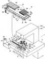
图1是本发明实施方式的激光加工装置的立体图。FIG. 1 is a perspective view of a laser processing apparatus according to an embodiment of the present invention.
图2是将图1所示的激光加工装置的一部分分解而示出的分解立体图。FIG. 2 is an exploded perspective view showing a part of the laser processing apparatus shown in FIG. 1 in an exploded manner.
图3的(a)是安装于图1所示的激光加工装置的水柱形成器的立体图,图3的(b)是将图3的(a)所示的水柱形成器分解而示出的分解立体图。FIG. 3( a ) is a perspective view of a water column former attached to the laser processing apparatus shown in FIG. 1 , and FIG. 3( b ) is an exploded view of the water column former shown in FIG. 3( a ) Stereogram.
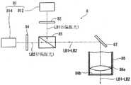
图4是用于对安装于图1所示的激光加工装置的激光光线照射单元的光学系统进行说明的框图。4 is a block diagram for explaining an optical system attached to a laser beam irradiation unit of the laser processing apparatus shown in FIG. 1 .
图5是示出安装于图1所示的激光加工装置的水柱形成构件的加工时的情形的局部放大剖视图。FIG. 5 is a partially enlarged cross-sectional view showing a state during processing of the water column forming member attached to the laser processing apparatus shown in FIG. 1 .
图6是示意性地示出第1激光光线和第2激光光线的脉冲宽度并且示出照射的定时的时序图。6 is a timing chart schematically showing the pulse widths of the first laser beam and the second laser beam and showing the timing of irradiation.
图7的(a)是示出通过图5所示的激光光线对晶片实施加工时产生的等离子体的局部放大剖视图,图7的(b)是示出从图7的(a)的结果得到的加工槽的局部放大剖视图。FIG. 7( a ) is a partially enlarged cross-sectional view showing plasma generated when the wafer is processed by the laser beam shown in FIG. 5 , and FIG. 7( b ) is a result obtained from the results of FIG. 7( a ) A partial enlarged cross-sectional view of the machined groove.
标号说明Label description
2:激光加工装置;4:液体提供机构;8:激光光线照射单元;81:激光振荡器;812:第1激光振荡器;814:第2激光振荡器;82:第一1/2波长板;84:第二1/2波长板;85:偏振光分束器;86:聚光器;86a:物镜;10:晶片;21:基台;22:保持单元;23:移动机构;26:框体;261:垂直壁部;262:水平壁部;30:X方向可动板;31:Y方向可动板;34:卡盘工作台;35:吸附卡盘;40:水柱形成器;42:壳体;421:上部部件(顶壁);422:下部部件;422c:侧壁;422d:底壁;423:喷出孔;424:空间部;43:高压水导入部;44:液体提供泵;45:过滤器;50:X方向移动机构(加工进给机构);52:Y方向移动机构;60:液体回收池;60A:开口;65:液体排出孔;70:液体回收路;90:对准单元;LB1:第1激光光线;LB2:第2激光光线;A:第1脉冲宽度;B:第2脉冲宽度;P1:第1等离子体;P2:第2等离子体;W:液体(纯水);S:水柱形成区域。2: Laser processing apparatus; 4: Liquid supply mechanism; 8: Laser beam irradiation unit; 81: Laser oscillator; 812: First laser oscillator; 814: Second laser oscillator; 82: First 1/2 wavelength plate ; 84: Second 1/2 wavelength plate; 85: Polarizing beam splitter; 86: Condenser; 86a: Objective lens; 10: Wafer; 21: Base; 22: Holding unit; 23: Moving mechanism; 26: Frame; 261: Vertical wall; 262: Horizontal wall; 30: X-direction movable plate; 31: Y-direction movable plate; 34: Chuck table; 35: Adsorption chuck; 40: Water column former; 42: housing; 421: upper part (top wall); 422: lower part; 422c: side wall; 422d: bottom wall; 423: ejection hole; 424: space part; 43: high-pressure water introduction part; Provide pump; 45: filter; 50: X-direction moving mechanism (processing feed mechanism); 52: Y-direction moving mechanism; 60: Liquid recovery pool; 60A: Opening; 65: Liquid discharge hole; 70: Liquid recovery path; 90: Alignment unit; LB1: 1st laser beam; LB2: 2nd laser beam; A: 1st pulse width; B: 2nd pulse width; P1: 1st plasma; P2: 2nd plasma; W: liquid (pure water); S: water column formation area.
具体实施方式Detailed ways
以下,参照附图对本发明实施方式的激光加工装置进行详细说明。Hereinafter, a laser processing apparatus according to an embodiment of the present invention will be described in detail with reference to the accompanying drawings.
图1示出了本实施方式的激光加工装置2的立体图。激光加工装置2具有:液体提供机构4,其配置在基台21上,向被加工物(例如硅制的晶片10)上提供液体;激光光线照射单元8,其对板状的被加工物照射激光光线;保持单元22,其保持该被加工物;移动机构23,其使激光光线照射单元8和保持单元22相对地移动;以及框体26,其由垂直壁部261和水平壁部262构成,该垂直壁部261在基台21上的移动机构23的侧方沿箭头Z所示的Z方向竖立设置,该水平壁部262从垂直壁部261的上端部沿水平方向延伸。FIG. 1 shows a perspective view of the
在框体26的水平壁部262的内部收纳有构成激光光线照射单元8的光学系统(随后详细叙述),该激光光线照射单元8对保持于保持单元22的晶片10照射激光光线。在水平壁部262的前端部下表面侧配设有构成激光光线照射单元8的一部分的聚光器86,并且在与聚光器86沿图中箭头X所示的方向相邻的位置配设有对准单元90。Inside the
对准单元90用于对保持在构成保持单元22的卡盘工作台34上的晶片10进行拍摄而检测待实施激光加工的位置。对准单元90具有对晶片10的正面进行拍摄的使用可见光线的拍摄元件(CCD),但根据构成晶片10的材质,优选包含:红外线照射构件,其照射红外线;光学系统,其捕捉由红外线照射构件照射的红外线;以及拍摄元件(红外线CCD),其输出与该光学系统捕捉到的红外线对应的电信号。The
如图所示,晶片10例如借助粘接带T而被环状框架F支承,并载置在构成卡盘工作台34的上表面的吸附卡盘35上而被吸引保持。另外,为了便于说明,上述激光加工装置2构成为整体上被省略的壳体等覆盖,以防止粉尘、尘埃等进入到内部。As shown in the figure, the
参照图1和图2对本实施方式的激光加工装置2进行详细说明。图2是示出在图1记载的激光加工装置2中将构成液体提供机构4的一部分的液体回收池60从激光加工装置2卸下并且将一部分分解后的状态的立体图。The
如图2所示,保持单元22包含:矩形状的X方向可动板30,其在图中箭头X所示的X方向上移动自如地搭载于基台21;矩形状的Y方向可动板31,其在箭头Y所示的与X方向垂直的Y方向上移动自如地搭载于X方向可动板30;圆筒状的支柱32,其固定于Y方向可动板31的上表面;以及矩形状的罩板33,其固定于支柱32的上端。在盖板33上配设有卡盘工作台34,该卡盘工作台34通过形成在盖板33上的长孔向上方延伸。卡盘工作台34构成为保持圆形状的被加工物,并且能够通过未图示的旋转驱动构件进行旋转。在卡盘工作台34的上表面配置有圆形状的吸附卡盘35,该吸附卡盘35由具有通气性的多孔质材料形成,并且实质上水平延伸。吸附卡盘35通过穿过支柱32的流路而与未图示的吸引构件连接,在吸附卡盘35的周围隔开间隔地配置有4个夹具36。夹具36在将晶片10固定于卡盘工作台34时将保持晶片10的框架F夹紧。由X方向、Y方向规定的平面实质上构成水平面。As shown in FIG. 2 , the
移动机构23包含X方向移动机构50和Y方向移动机构52。X方向移动机构50将电动机50a的旋转运动经由滚珠丝杠50b转换为直线运动并传递给X方向可动板30,使X方向可动板30沿着基台21上的导轨27、27在X方向上进退。Y方向移动机构52将电动机52a的旋转运动经由滚珠丝杠52b转换为直线运动并传递给Y方向可动板31,使Y方向可动板31沿着X方向可动板30上的导轨37、37在Y方向上进退。另外,虽然省略了图示,但在卡盘工作台34、X方向移动机构50以及Y方向移动机构52上分别配设有位置检测构件,准确地检测卡盘工作台34的X方向的位置、Y方向的位置、周向的旋转位置,从而能够对X方向移动机构50、Y方向移动机构52以及未图示的卡盘工作台34的旋转驱动构件进行驱动而将卡盘工作台34准确地定位于任意的位置和角度。上述X方向移动机构50是使保持单元22沿加工进给方向移动的加工进给机构,Y方向移动机构52是使保持单元22沿分度进给方向移动的分度进给构件。The
如图1所示,液体提供机构4具有:水柱形成器40,其在本实施方式中构成水柱形成构件;液体提供泵44;过滤器45;液体回收池60;管46a,其连接水柱形成器40和液体提供泵44;以及管46b,其连接液体回收池60和过滤器45。另外,管46a、管46b优选局部或整体上由挠性软管形成。As shown in FIG. 1, the liquid supply mechanism 4 includes: a water column former 40, which constitutes a water column formation member in this embodiment; a
如图3的(a)所示,水柱形成器40配设在聚光器86的下端部。水柱形成器40的分解图在图3的(b)中示出。从图3的(b)可知,水柱形成器40包含壳体42和向壳体42导入高压水的高压水导入部43。壳体42俯视时呈大致矩形状,由构成本实施方式的顶壁的上部部件421和与上部部件421对置的下部部件422构成。As shown in FIG. 3( a ), the water column former 40 is arranged at the lower end of the
如图3的(b)所示,在上部部件421上形成有圆形的开口部421c,该开口部421c从上表面421a贯通到背面421b侧而供聚光器86插入。下部部件422具有:底壁422d,其在与上部部件421的开口部421c对置的区域形成有贯通到下部部件422的下表面422b侧的喷出孔423;以及侧壁422c,其围绕由上部部件421的下表面421b和底壁422d形成的空间部424。在与高压水导入部43连结的一侧的侧壁422f上形成有用于向空间部424提供液体的液体提供口422e。As shown in FIG.3(b), the
高压水导入部43具有提供液体W的提供口43a,通过从Y方向组装在壳体42的液体提供口422f所开口的侧壁上而形成水柱形成器40。The high-pressure
水柱形成器40具有上述那样的结构,从基于图1说明的液体提供泵44喷出的液体W经由高压水导入部43而被提供到壳体42的液体提供口422e,流过壳体42的空间部424并从形成在底壁422d上的喷出孔423喷出。The water column former 40 has the above-mentioned structure, and the liquid W discharged from the
返回图1和图2,对液体回收池60进行说明。如图2所示,液体回收池60具有外框体61和两个防水罩66。Returning to FIGS. 1 and 2 , the
外框体61具有:一对外侧壁62a,它们在图中箭头X所示的X方向上延伸;一对外侧壁62b,它们在图中箭头Y所示的Y方向上延伸;各一对内侧壁63a、63b,它们在外侧壁62a、62b的内侧隔开规定的间隔平行地配设;以及底壁64,其连结外侧壁62a、62b和内侧壁63a、63b的下端。由外侧壁62a、62b、内侧壁63a、63b以及底壁64形成长度方向沿着X方向且宽度方向沿着Y方向的长方形的液体回收路70。在构成液体回收路70的内侧壁63a、63b的内侧形成有上下贯通的开口。在构成液体回收路70的底壁64上沿X方向和Y方向设置有微小的倾斜,在液体回收路70的作为最低位置的角部(图中左侧的角部)配设有液体排出孔65。液体排出孔65与管46b连接,经由管46b而与过滤器45连接。另外,外框体61优选整体上由耐腐蚀和抗生锈的不锈钢制的板材形成。The
两个防水罩66具有:固定配件66a,其由门型形状构成;以及波纹状的树脂制的罩部件66b,其两端固定于固定配件66a。固定配件66a的尺寸形成为能够横跨在Y方向上对置配置的外框体61的两个内侧壁63a。两个防水罩66的固定配件66a的一方分别固定于以在外框体61的X方向上对置的方式配设的内侧壁63b。这样构成的液体回收池60通过未图示的固定件固定在激光加工装置2的基台21上。保持单元22的盖板33以被两个防水罩66的固定配件66a彼此夹持的方式安装。另外,盖部件33的X方向上的端面呈与固定配件66a相同的门型形状,是与固定配件66a同样在Y方向上横跨外框体61的内侧壁63a的尺寸。因此,在将液体回收池60的外框体61设置在基台21上之后,盖部件33被安装于防水罩66。根据上述结构,当盖板33通过X方向移动机构50在X方向上移动时,盖板33沿着液体回收池60的内侧壁63a移动。另外,防水罩66和盖部件33的安装方法不限于上述步骤,例如,在将两个防水罩66安装于外框架61的内侧壁63b之前,也可以预先安装盖部件33,将防水罩66与盖部件33一起安装于已先安装在基台21上的外框体61。The two
返回图1继续进行说明,液体提供机构4通过具有上述结构,从液体提供泵44的喷出口44a喷出的液体W经由管46a而被提供到水柱形成器40。提供到水柱形成器40的液体W从形成在基于图3的(b)说明的水柱形成器40的壳体42的底壁422d上的喷出孔423向下方喷出。从水柱形成器40喷出的液体W在盖板33和防水罩66上流过并向液体回收池60流下。流下至液体回收池60的液体W流过液体回收路70并汇集在设置于液体回收路70的最低位置的液体排出孔65中。汇集在液体排出孔65中的液体W经由管46b被引导至过滤器45,通过过滤器45将激光加工屑(碎屑)、尘埃等除去而返回到液体提供泵44。这样,由液体提供泵44喷出的液体W在液体提供机构4内循环。Returning to FIG. 1 and continuing the description, the liquid supply mechanism 4 has the above-described structure, and the liquid W ejected from the
图4是示出激光光线照射单元8的光学系统的概略的框图。如图4所示,激光光线照射单元8包含:激光振荡器81,其具有第1激光振荡器812和第2激光振荡器814,该第1激光振荡器812射出脉冲状的激光光线、即脉冲宽度短的第1激光光线LB1,该第2激光振荡器814射出脉冲状的激光光线、即脉冲宽度长的第2激光光线LB2;1/2波长板82,其对入射的第1激光光线LB1赋予相当于1/2波长的量的相位差并使直线偏振光旋转;1/2波长板84,其对入射的第2激光光线LB2赋予相当于1/2波长的量的相位差并使直线偏振光旋转;偏振光分束器85,其反射通过了1/2波长板82的第1激光光线LB1的S偏振光并且使通过了1/2波长板84的第2激光光线LB2的P偏振光通过,对该反射后的该第1激光光线LB1(S偏振光)和该通过后的第2激光光线LB2(P偏振光)以照射到晶片10上的同一部位的方式进行合波,作为激光光线LB1+LB2而输出;反射镜87,其使从偏振光分束器85输出的激光光线LB1+LB2的照射方向变更90°;以及聚光器86,其对激光光线LB1+LB2进行聚光并照射在保持单元22所保持的晶片10上。第1激光振荡器812和第2激光振荡器814例如振荡出对于被加工物具有吸收性的波长的激光。另外,虽然省略了图示,但在激光光线照射单元8的光学系统中可以适当包含变更各激光光线的输出的衰减器、变更各激光光线的光路的反射镜等。FIG. 4 is a block diagram showing the outline of the optical system of the laser
在聚光器86的内部配设有物镜86a,该物镜86a使激光光线LB1+LB2聚光并照射在晶片10上。物镜86a位于上述反射镜87的下方,对被反射镜87反射的激光光线LB1+LB2进行聚光而照射。在聚光器86的下端部配设有玻璃部件86b,聚光器86的下端部被玻璃部件86b封闭。该玻璃部件86b使上述激光光线LB1+LB2透过,并且防止导入到壳体42的空间部424的高压液体W进入到聚光器86内。另外,也可以代替用玻璃部件86b封闭聚光器86的下端部,而是用同样的玻璃部件将形成在壳体42的上部部件421的开口部421c的下表面侧封闭。此外,激光光线照射单元8具有未图示的聚光点位置调整构件,对由聚光器86聚光的激光光线LB1+LB2的聚光点的位置在Z方向上进行调整。An
本发明的激光加工装置2具有大致如上所述的结构,以下对其作用进行说明。The
在通过本实施方式的激光加工装置2实施激光加工时,如图1所示,对于借助粘接带T被环状框架F支承的板状的被加工物,例如准备在正面形成有器件的由硅(Si)构成的晶片10。在准备好晶片10之后,使形成有器件的正面朝上而将晶片10放置在卡盘工作台34的吸附卡盘35上,使未图示的吸引构件进行动作并且通过夹具36等进行固定。When laser processing is performed by the
在将晶片10保持于吸附卡盘35之后,通过移动机构23使卡盘工作台34在X方向和Y方向上适当移动,将卡盘工作台34上的晶片10定位在对准单元90的正下方。在将晶片10定位在对准单元90的正下方之后,通过对准单元90对晶片10上进行拍摄。接着,根据由对准单元90拍摄到的晶片10的图像,通过图案匹配等方法检测晶片10的待加工位置(对准工序)。根据通过该对准工序得到的位置信息而使卡盘工作台34移动,从而将聚光器86定位在晶片10上的加工开始位置的上方。After holding the
在实施了聚光器86与晶片10的对位之后,对液体提供机构4填补足够所需的液体W,并使液体提供泵44动作。作为在液体提供机构4的内部循环的液体W,例如利用纯水。After the alignment of the
图5示出沿图3所示的A-A切断后的水柱形成器40的局部放大剖视图,并且示出一边导入高压的液体W而形成水柱Wp一边照射激光光线LB1+LB2而实施激光加工的方式。从图5可知,液体提供机构4的水柱形成器40配设在聚光器86的下端部,并且被设定为在将聚光点定位于晶片10的正面高度时,由构成水柱形成器40的壳体42的下表面422b和晶片10的正面形成例如10mm~20mm左右的水柱形成区域S。5 shows a partially enlarged cross-sectional view of the water column former 40 cut along the line A-A shown in FIG. 3 , and shows a method of performing laser processing by irradiating laser beams LB1 + LB2 while introducing a high-pressure liquid W to form a water column Wp. As can be seen from FIG. 5 , the water column former 40 of the liquid supply mechanism 4 is arranged at the lower end portion of the
液体提供机构4通过具有上述结构,从液体提供泵44的喷出口44a喷出的液体W被提供到水柱形成器40。提供到水柱形成器40的液体W经由高压水导入部43而导入到壳体42内的空间部424,并从形成于底壁422d的喷出孔423向下方喷出。如图5所示,从喷出孔423喷出的液体W在壳体42的下表面422b与晶片10之间的水柱形成区域S形成线状的水柱Wp,然后在晶片10上流过并向卡盘工作台34外流出,流过上述液体回收池60的液体回收路70并汇集在形成于液体回收路70的液体排出孔65中。汇集于液体排出孔65的液体W经由管46b而被引导至过滤器45,在过滤器45中被净化而返回至液体提供泵44,从而在液体提供机构4内循环。另外,由从液体提供泵44喷出的液体W形成的空间部424内的压力例如为2Mpa~50Mpa,并且从喷出孔423喷出而形成的线状的水柱Wp的直径为20μm~150μm。The liquid supply mechanism 4 has the above-described structure, and the liquid W ejected from the
在液体W在液体提供机构4中稳定地循环并且形成有水柱Wp的状态下,通过使激光光线照射单元8进行动作并使构成移动机构23的X方向移动机构50进行动作,使保持单元22和激光光线照射单元8在加工进给方向(X方向)上从上述加工开始位置以预定的移动速度相对地移动。In a state where the liquid W is stably circulated in the liquid supply mechanism 4 and the water column Wp is formed, the holding
这里,在图5的基础上,参照图6、图7对由本实施方式的激光光线照射单元8实现的激光加工进一步进行详细说明。Here, in addition to FIG. 5 , the laser processing performed by the laser
如图5所示,从聚光器86照射的激光光线LB1+LB2通过充满液体W的水柱形成器40的空间部424和喷出孔423,在水柱Wp内传递并照射在晶片10的被加工位置(分割预定线)。激光光线LB1+LB2是如上所述将第1激光光线LB1和第2激光光线LB2合波而成的激光光线,但如图6所示,第1激光光线LB1被设定为极短的脉冲宽度A,第2激光光线LB2被设定为比第1激光光线LB1长的脉冲宽度B,第2激光光线LB2与第1激光光线LB1同步照射。As shown in FIG. 5 , the laser beams LB1 + LB2 irradiated from the
另外,上述激光加工装置2中的激光加工条件例如可以按照以下的加工条件实施。In addition, the laser processing conditions in the above-mentioned
<第1激光振荡器><1st laser oscillator>
第1激光光线的波长:355nm、532nm、1064nmWavelength of the first laser beam: 355nm, 532nm, 1064nm
平均输出:10W~30WAverage output: 10W~30W
重复频率:1MHz~10MHzRepetition frequency: 1MHz~10MHz
脉冲宽度:50fs~50psPulse width: 50fs~50ps
<第2激光振荡器><Second laser oscillator>
第2激光光线的波长:355nm、532nm、1064nmWavelength of the second laser beam: 355nm, 532nm, 1064nm
平均输出:30WAverage output: 30W
重复频率:1MHz~10MHzRepetition frequency: 1MHz~10MHz
脉冲宽度:50nsPulse width: 50ns
从图6和图7的(a)可知,第2激光光线LB2相对于等离子体P1以导入的方式照射,其中,该等离子体P1是通过第1激光光线LB1照射在晶片10的加工位置而在晶片10的正面附近产生的。在本实施方式中,如基于图6说明的那样,第1激光光线LB1被设定为极短的脉冲宽度,并且第2激光光线LB2被设定为比第1激光光线LB1长的脉冲宽度,进一步来说,第1激光光线LB1被设定为峰值功率密度高,第2激光光线LB2被设定为峰值功率密度比第1激光光线LB1大幅降低。As can be seen from FIG. 6 and FIG. 7( a ), the second laser beam LB2 is irradiated in an introductory manner with respect to the plasma P1 that is irradiated at the processing position of the
当如上所述对晶片10照射激光光线LB1+LB2时,如图7的(a)所示,通过照射峰值功率密度高且脉冲宽度短的第1激光光线LB1而在晶片10的正面产生第1等离子体P1。接着,第2激光光线LB2通过与第1激光光线LB1同步地照射而朝向该第1等离子体P1进行照射。由此,第2激光光线LB2的能量被引导至第1等离子体P1,使第1等离子体P1向第2等离子体P2成长。然后,沿着分割预定线照射激光光线LB1+LB2,如图7的(b)所示,朝向照射位置的下方实施各向同性优异的激光加工而掘进成圆形,沿着分割预定线形成期望深度的加工槽100。而且,通过水柱Wp的压力使由激光光线LB1+LB2的照射而产生的气泡破裂,并且与形成水柱Wp的液体W一起从晶片10的加工区域迅速排出,从而不会妨碍连续照射的激光光线的照射。When the
此外,即使碎屑从晶片10的正面排出到液体W中,也能够与上述气泡一起从晶片10上迅速地释放。包含上述气泡和碎屑的液体W如上所述在盖板33和防水罩66上流过并被引导到液体回收池60的液体回收路70。被引导至液体回收路70的液体W一边将由激光加工产生的气泡向外部释放一边流过液体回收路70,并从形成在液体回收路70的最底部的液体排出孔65排出。从液体排出孔65排出的液体W经由管46b而被引导至过滤器45,并再次被提供到液体提供泵44。这样,通过液体W在液体提供机构4中循环,通过过滤器45来适当捕捉碎屑、灰尘等,将液体W维持为清洁的状态。In addition, even if the debris is discharged into the liquid W from the front surface of the
在对第1方向的分割预定线实施了上述激光加工之后,通过使移动机构23进行动作,将聚光器86定位于在Y方向上与已经实施了激光加工的第1方向的分割预定线相邻的未加工的分割预定线的一端部,实施与上述激光加工相同的激光加工。然后,在对沿该第1方向形成的所有的分割预定线实施了该激光加工之后,通过使卡盘工作台34旋转90度,对在与先前加工的第1方向的分割预定线正交的未加工的第2方向上延伸的分割预定线也实施同样的激光加工。这样,能够对晶片10上的所有的分割预定线实施激光加工,形成作为分割起点的加工槽100。After the above-described laser processing is performed on the line to be divided in the first direction, by operating the moving
在本实施方式中,如上所述,使激光光线LB1+LB2在水柱Wp内传递并照射在期望的照射位置,通过从第1等离子体P1成长的第2等离子体P2实施加工。与此相对,在仅通过第1激光光线LB1那样脉冲宽度短的激光光线实施加工的情况下,由于在加工方向上存在各向异性,所以加工部的截面形状为V型,当从正面起沿深度方向进行加工时,加工速度急剧下降。但是,在如本实施方式那样照射将脉冲宽度短的第1激光光线LB1和脉冲宽度长的第2激光光线LB2合波后的激光光线LB1+LB2的情况下,如基于图7说明的那样,成为各向同性优异的加工,能够朝向该照射位置的下方在加工速度不降低的情况下掘进成圆形,能够以良好的加工速度沿着分割预定线形成期望的深度的加工槽100。In the present embodiment, as described above, the laser beams LB1 + LB2 are transmitted in the water column Wp and irradiated at a desired irradiation position, and processing is performed by the second plasma P2 grown from the first plasma P1. On the other hand, when processing is performed only with a laser beam with a short pulse width, such as the first laser beam LB1, since there is anisotropy in the processing direction, the cross-sectional shape of the processed portion is V-shaped, and when the direction from the front When machining in the depth direction, the machining speed drops sharply. However, when the laser beam LB1+LB2 obtained by combining the first laser beam LB1 with a short pulse width and the second laser beam LB2 with a long pulse width is irradiated as in the present embodiment, as described with reference to FIG. 7 , It becomes a process with excellent isotropy, and it is possible to excavate in a circular shape toward the downward direction of the irradiation position without reducing the process speed, and to form the
根据本实施方式,即使不在晶片10的正面上包覆液状树脂,也能够防止碎屑附着在晶片10的正面,能够削减液状树脂的成本,节省包覆和除去液状树脂的工夫,因此生产率提高。According to the present embodiment, even if the liquid resin is not coated on the front surface of the
并且,第1激光光线LB1在由水柱形成器40形成的水柱Wp内传递并照射在晶片10上,从而产生第1等离子体P1。此时,第1等离子体P1被封入在流下到水柱Wp内的液体W的层中而产生,因此抑制过度膨胀,进而减轻热的影响。然后,第2激光光线LB2被由脉冲宽度短的第1激光光线LB1生成的第1等离子体P1吸收,从而在流下到水柱Wp内的液体W的层中产生第2等离子体而实施加工,与仅利用第2脉冲激光光线LB实施激光加工的情况相比,对晶片10的分割预定线周围造成的热影响有限,提高了将晶片10分割成一个个器件芯片时的抗弯强度。即,通过如本实施方式那样使第1激光光线LB1和第2激光光线LB2合波并在水柱Wp内传递而向被加工物照射激光光线LB1+LB2,与单独地照射第1激光光线LB1和第2激光光线LB2中的任意一个来实施激光加工的情况相比,能够进行优异的激光加工。And the 1st laser beam LB1 is transmitted in the water column Wp formed by the water column former 40, and is irradiated on the
根据本发明,不限于上述实施方式,可提供各种变形例。例如,在上述实施方式中,以第2激光光线LB2是脉冲状的激光光线为前提进行了说明,但本发明不限于此。第2激光光线LB2只要是以比第1激光光线LB2的脉冲宽度长的宽度照射的激光光线即可,因此也可以是连续波(CW)。即,在本发明的“脉冲宽度长的第2激光光线”中还包含作为连续波(CW)的激光光线。According to the present invention, it is not limited to the above-described embodiment, and various modifications can be provided. For example, in the above-mentioned embodiment, the description has been made on the premise that the second laser beam LB2 is a pulsed laser beam, but the present invention is not limited to this. The second laser beam LB2 may be a continuous wave (CW) as long as it is a laser beam irradiated with a width longer than the pulse width of the first laser beam LB2. That is, the "second laser beam with a long pulse width" of the present invention also includes a continuous wave (CW) laser beam.
在上述实施方式中,第2激光光线LB2与第1激光光线LB1同步地射出,如图6所示,第2激光光线LB2被说明成以与第1激光光线LB1同时照射的方式从第1激光振荡器812和第2激光振荡器814射出,但本发明不限于此。例如,还存在如下的情况:在照射了第1激光光线LB1之后,在由第1激光光线LB1产生的第1等离子体P1消灭之前照射第2激光光线LB2。这样,只要在照射了第1激光光线LB1之后且第1等离子体P1消灭之前从第2激光振荡器814射出第2激光光线LB2,就能够起到与上述相同的作用效果。In the above-described embodiment, the second laser beam LB2 is emitted in synchronization with the first laser beam LB1. As shown in FIG. 6, the second laser beam LB2 is described as being emitted from the first laser beam simultaneously with the first laser beam LB1 The
Claims (2)
Priority Applications (1)
| Application Number | Priority Date | Filing Date | Title |
|---|---|---|---|
| CN202011416676.0ACN114589422A (en) | 2020-12-07 | 2020-12-07 | Laser processing apparatus |
Applications Claiming Priority (1)
| Application Number | Priority Date | Filing Date | Title |
|---|---|---|---|
| CN202011416676.0ACN114589422A (en) | 2020-12-07 | 2020-12-07 | Laser processing apparatus |
Publications (1)
| Publication Number | Publication Date |
|---|---|
| CN114589422Atrue CN114589422A (en) | 2022-06-07 |
Family
ID=81802920
Family Applications (1)
| Application Number | Title | Priority Date | Filing Date |
|---|---|---|---|
| CN202011416676.0APendingCN114589422A (en) | 2020-12-07 | 2020-12-07 | Laser processing apparatus |
Country Status (1)
| Country | Link |
|---|---|
| CN (1) | CN114589422A (en) |
Citations (5)
| Publication number | Priority date | Publication date | Assignee | Title |
|---|---|---|---|---|
| JP2006255769A (en)* | 2005-03-18 | 2006-09-28 | Shibuya Kogyo Co Ltd | Hybrid laser beam machining apparatus |
| US20070023691A1 (en)* | 2005-07-12 | 2007-02-01 | Disco Corporation | Laser processing apparatus |
| CN101844274A (en)* | 2009-03-24 | 2010-09-29 | 速技能机械有限公司 | The manufacture method of laser processing device, laser processing device, laser processing |
| CN101992351A (en)* | 2009-08-21 | 2011-03-30 | 株式会社迪思科 | Laser processing machine |
| WO2019156183A1 (en)* | 2018-02-09 | 2019-08-15 | 国立大学法人東京大学 | Processing device, processing method, and transparent substrate |
- 2020
- 2020-12-07CNCN202011416676.0Apatent/CN114589422A/enactivePending
Patent Citations (5)
| Publication number | Priority date | Publication date | Assignee | Title |
|---|---|---|---|---|
| JP2006255769A (en)* | 2005-03-18 | 2006-09-28 | Shibuya Kogyo Co Ltd | Hybrid laser beam machining apparatus |
| US20070023691A1 (en)* | 2005-07-12 | 2007-02-01 | Disco Corporation | Laser processing apparatus |
| CN101844274A (en)* | 2009-03-24 | 2010-09-29 | 速技能机械有限公司 | The manufacture method of laser processing device, laser processing device, laser processing |
| CN101992351A (en)* | 2009-08-21 | 2011-03-30 | 株式会社迪思科 | Laser processing machine |
| WO2019156183A1 (en)* | 2018-02-09 | 2019-08-15 | 国立大学法人東京大学 | Processing device, processing method, and transparent substrate |
Similar Documents
| Publication | Publication Date | Title |
|---|---|---|
| CN109676259B (en) | Laser processing device | |
| CN112108778A (en) | Laser processing apparatus | |
| CN110625275B (en) | Laser processing device | |
| CN101165877B (en) | Laser processing method for gallium arsenide wafer | |
| TW201933467A (en) | Laser processing method | |
| TWI780161B (en) | Laser processing device and laser processing method | |
| CN109746572B (en) | Laser processing apparatus | |
| CN109676248B (en) | Laser processing apparatus | |
| CN114762912A (en) | Laser processing device | |
| TWI887289B (en) | Laser processing equipment | |
| CN114589422A (en) | Laser processing apparatus | |
| CN113178415A (en) | Wafer processing method and wafer processing apparatus | |
| TWI804637B (en) | Laser processing device | |
| JP2013010124A (en) | Laser processing device | |
| JP5511514B2 (en) | Processing method of optical device wafer | |
| JP2024163571A (en) | Processing Equipment | |
| JP2013010123A (en) | Laser processing device |
Legal Events
| Date | Code | Title | Description |
|---|---|---|---|
| PB01 | Publication | ||
| PB01 | Publication | ||
| SE01 | Entry into force of request for substantive examination | ||
| SE01 | Entry into force of request for substantive examination |