CN114576653A - Oil thrower with special-shaped flow disturbing column - Google Patents
Oil thrower with special-shaped flow disturbing columnDownload PDFInfo
- Publication number
- CN114576653A CN114576653ACN202210277285.8ACN202210277285ACN114576653ACN 114576653 ACN114576653 ACN 114576653ACN 202210277285 ACN202210277285 ACN 202210277285ACN 114576653 ACN114576653 ACN 114576653A
- Authority
- CN
- China
- Prior art keywords
- oil
- special
- fuel
- column
- shaped
- Prior art date
- Legal status (The legal status is an assumption and is not a legal conclusion. Google has not performed a legal analysis and makes no representation as to the accuracy of the status listed.)
- Pending
Links
- 238000002485combustion reactionMethods0.000claimsabstractdescription17
- 239000007921spraySubstances0.000claims2
- 238000005507sprayingMethods0.000claims2
- 206010066054DysmorphismDiseases0.000claims1
- 239000000446fuelSubstances0.000abstractdescription35
- 238000000889atomisationMethods0.000abstractdescription15
- 230000000694effectsEffects0.000abstractdescription15
- 238000002347injectionMethods0.000abstractdescription7
- 239000007924injectionSubstances0.000abstractdescription7
- 239000003921oilSubstances0.000abstract5
- 239000010705motor oilSubstances0.000abstract1
- 238000010586diagramMethods0.000description3
- 238000000034methodMethods0.000description2
- 230000009286beneficial effectEffects0.000description1
- 239000003344environmental pollutantSubstances0.000description1
- 239000007788liquidSubstances0.000description1
- 239000003595mistSubstances0.000description1
- 231100000719pollutantToxicity0.000description1
- 239000000243solutionSubstances0.000description1
Images


Classifications
- F—MECHANICAL ENGINEERING; LIGHTING; HEATING; WEAPONS; BLASTING
- F23—COMBUSTION APPARATUS; COMBUSTION PROCESSES
- F23R—GENERATING COMBUSTION PRODUCTS OF HIGH PRESSURE OR HIGH VELOCITY, e.g. GAS-TURBINE COMBUSTION CHAMBERS
- F23R3/00—Continuous combustion chambers using liquid or gaseous fuel
- F23R3/28—Continuous combustion chambers using liquid or gaseous fuel characterised by the fuel supply
- F23R3/38—Continuous combustion chambers using liquid or gaseous fuel characterised by the fuel supply comprising rotary fuel injection means
- Y—GENERAL TAGGING OF NEW TECHNOLOGICAL DEVELOPMENTS; GENERAL TAGGING OF CROSS-SECTIONAL TECHNOLOGIES SPANNING OVER SEVERAL SECTIONS OF THE IPC; TECHNICAL SUBJECTS COVERED BY FORMER USPC CROSS-REFERENCE ART COLLECTIONS [XRACs] AND DIGESTS
- Y02—TECHNOLOGIES OR APPLICATIONS FOR MITIGATION OR ADAPTATION AGAINST CLIMATE CHANGE
- Y02T—CLIMATE CHANGE MITIGATION TECHNOLOGIES RELATED TO TRANSPORTATION
- Y02T10/00—Road transport of goods or passengers
- Y02T10/10—Internal combustion engine [ICE] based vehicles
- Y02T10/12—Improving ICE efficiencies
Landscapes
- Engineering & Computer Science (AREA)
- Chemical & Material Sciences (AREA)
- Combustion & Propulsion (AREA)
- Mechanical Engineering (AREA)
- General Engineering & Computer Science (AREA)
- Nozzles For Spraying Of Liquid Fuel (AREA)
Abstract
Translated fromChinese
Description
Translated fromChinese技术领域technical field
本发明属于燃气轮机燃烧室领域,具体涉及一种带有异形扰流柱的甩油盘。The invention belongs to the field of gas turbine combustion chambers, and in particular relates to an oil slinger with a special-shaped spoiler column.
背景技术Background technique
燃气轮机作为一种常见的动力装置,其性能的改善对诸多行业以及环境都会有巨大的益处。为了提高燃气轮机的燃烧效率、减少污染排放,对燃料的雾化效果研究是其中的重要环节。燃油的雾化效果关系到燃油能否完全燃烧,能否与空气达到良好的掺混效果,从而实现燃油的高效燃烧,提高燃烧效率并降低污染物的排放。因此,甩油盘对燃油的雾化实现效果,显得尤为重要。As a common power plant, the improvement of gas turbine performance will have huge benefits for many industries and the environment. In order to improve the combustion efficiency of gas turbines and reduce pollution emissions, the research on the atomization effect of fuel is an important link. The atomization effect of the fuel is related to whether the fuel can be completely burned and whether it can achieve a good mixing effect with the air, so as to realize the efficient combustion of the fuel, improve the combustion efficiency and reduce the emission of pollutants. Therefore, it is particularly important to realize the atomization effect of the oil thrower on the fuel.
甩油盘是用于小型发动机的供油装置。它通过甩油盘的旋转对燃油做功,使燃油从喷油孔高速喷出,实现燃油的雾化。而甩油盘的转速一般与发动机转轴的转速一致,随其变化。燃油的雾化质量与转轴的转速直接相关,高转速时雾化效果较好,而低转速时质量则较差。较差的燃油雾化效果会带来较低的燃烧效率以及较高的污染排放。因此,提高甩油盘低转速时的雾化效果能有效解决上述问题。A slinger is an oil supply device for small engines. It works on the fuel through the rotation of the oil thrower, so that the fuel is sprayed out from the fuel injection hole at a high speed to realize the atomization of the fuel. The speed of the oil slinger is generally consistent with the speed of the engine shaft, and changes with it. The atomization quality of the fuel is directly related to the speed of the rotating shaft. The atomization effect is better at high speed, and the quality is poor at low speed. Poor fuel atomization results in lower combustion efficiency and higher pollution emissions. Therefore, improving the atomization effect of the oil slinger at low rotation speed can effectively solve the above problems.
发明内容SUMMARY OF THE INVENTION
本发明要解决的技术问题是提出一种带有异形扰流柱的甩油盘,通过设置狭长的进油孔,提高燃油进入甩油盘盘腔的速度。通过设置两种扰流柱,提高燃油经过甩油盘的雾化效果,并强化燃油与燃烧室内空气的掺混效果。最终达到提高燃油雾化效果,提高燃烧室内的燃烧效率,减少污染排放的目的。The technical problem to be solved by the present invention is to provide an oil slinger with a special-shaped spoiler column. By setting narrow and long oil inlet holes, the speed of fuel entering into the cavity of the oil slinger is increased. By setting up two kinds of spoiler columns, the atomization effect of fuel passing through the oil slinger is improved, and the mixing effect of fuel and the air in the combustion chamber is enhanced. Finally, the purpose of improving the fuel atomization effect, improving the combustion efficiency in the combustion chamber and reducing pollution emissions is achieved.
技术方案Technical solutions
本发明的目的在于提供一种带有异形扰流柱的甩油盘。The purpose of the present invention is to provide an oil throwing pan with a special-shaped spoiler column.
本发明技术方案如下:The technical scheme of the present invention is as follows:
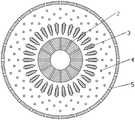
为解决其技术问题,所述的一种带有异形扰流柱的甩油盘,其特征在于:所述甩油盘包括甩油盘主体、进油口、异形扰流柱、外侧扰流柱、喷油孔。In order to solve the technical problem, the oil slinger with a special-shaped spoiler column is characterized in that: the oil slinger includes a main body of the oil thrower, an oil inlet, a special-shaped spoiler column, and an outer spoiler column. , fuel injection hole.
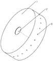
所述的一种带有异形扰流柱的甩油盘,其特征在于:甩油盘主体呈扁圆柱状,中部为半贯通状态,可直接安装于转轴之上。甩油盘的直径为200~240mm,厚度为50~70mm,具体尺寸按燃烧室尺寸确定。The oil slinger with a special-shaped spoiler is characterized in that: the main body of the oil slinger is in the shape of a flat cylinder, and the middle part is in a semi-through state, which can be directly installed on the rotating shaft. The diameter of the oil throwing pan is 200-240mm and the thickness is 50-70mm, and the specific size is determined according to the size of the combustion chamber.
所述的一种带有异形扰流柱的甩油盘,其特征在于:进油孔为细长的圆柱形,沿径向布置,进油孔内侧连接输油通道,外侧通入甩油盘腔体内。输油孔直径为1~3mm,长度为20~40mm,具体数量可根据发动机功率确定。The oil slinger with special-shaped spoiler is characterized in that: the oil inlet hole is a slender cylindrical shape, arranged along the radial direction, the inner side of the oil inlet hole is connected to the oil conveying channel, and the outer side is connected to the oil slinger pan inside the cavity. The diameter of the oil delivery hole is 1~3mm, and the length is 20~40mm. The specific number can be determined according to the engine power.
所述的一种带有异形扰流柱的甩油盘,其特征在于:异形扰流柱呈锯齿状,沿圆周均匀布置在进油孔外侧,共18个。锯齿尖方向与径向夹角为30~45°。The oil slinger with special-shaped spoiler column is characterized in that: the special-shaped spoiler column is in a zigzag shape, and is evenly arranged outside the oil inlet hole along the circumference, with a total of 18. The angle between the direction of the sawtooth tip and the radial direction is 30 to 45°.
所述的一种带有异形扰流柱的甩油盘,其特征在于:外侧扰流柱为圆柱形,沿周向均匀布置在异形扰流柱外侧,共分为三层,每层交错布置,直径为2~5mm。The oil slinger with a special-shaped spoiler column is characterized in that: the outer spoiler column is cylindrical, and is evenly arranged outside the special-shaped spoiler column along the circumferential direction. It is divided into three layers, and each layer is arranged in a staggered manner. , the diameter is 2 ~ 5mm.
所述的一种带有异形扰流柱的甩油盘,其特征在于:喷油孔直径为1~3mm,喷射方向为径向,沿周向均匀布置,共24个。The oil slinger with special-shaped spoiler column is characterized in that: the diameter of the oil injection holes is 1-3 mm, the injection direction is radial, and there are 24 evenly arranged along the circumferential direction.
本发明具有以下有益效果:The present invention has the following beneficial effects:
本发明提出了一种带有异形扰流柱的甩油盘,通过设置狭长的进油孔,提高燃油进入甩油盘盘腔的速度。通过设置两种扰流柱,提高燃油经过甩油盘的雾化效果,并强化燃油与燃烧室内空气的掺混效果。最终达到提高燃油雾化效果,提高燃烧室内的燃烧效率,减少污染排放的目的。The invention proposes an oil slinger with a special-shaped spoiler column. By arranging narrow and long oil inlet holes, the speed of fuel entering into the cavity of the oil slinger is improved. By setting up two kinds of spoiler columns, the atomization effect of fuel passing through the oil slinger is improved, and the mixing effect of fuel and the air in the combustion chamber is enhanced. Finally, the purpose of improving the fuel atomization effect, improving the combustion efficiency in the combustion chamber and reducing pollution emissions is achieved.
附图说明Description of drawings
图1:一种带有异形扰流柱的甩油盘剖视图Figure 1: A cross-sectional view of an oil slinger with a special-shaped spoiler column
图2:一种带有异形扰流柱的甩油盘整体示意图Figure 2: An overall schematic diagram of an oil slinger with a special-shaped spoiler column
图3:一种带有异形扰流柱的甩油盘进油孔结构示意图Figure 3: Schematic diagram of the oil inlet hole structure of an oil slinger with a special-shaped spoiler column
图4:一种带有异形扰流柱的甩油盘异形扰流柱局部示意图Figure 4: Partial schematic diagram of a special-shaped spoiler column of an oil slinger with a special-shaped spoiler column
图中:1、甩油盘主体;2、进油孔;3、异形扰流柱;4、外侧扰流柱;5、喷油孔。In the figure: 1. The main body of the oil thrower; 2. The oil inlet hole; 3. The special-shaped spoiler column; 4. The outer spoiler column; 5. The fuel injection hole.
具体实施方式Detailed ways
现结合附图对本发明作进一步描述:Now in conjunction with the accompanying drawings, the present invention will be further described:
结合图1,2,本发明提供了一种带有异形扰流柱的甩油盘。With reference to Figures 1 and 2, the present invention provides an oil slinger with a special-shaped spoiler column.
具体过程:燃油经进油孔2进入甩油盘腔体,细长的进油孔2使得燃油进入盘腔时具有更高的速度。高速的燃油射流经异形扰流柱3,被迅速撕裂破碎成大量小液滴。然后燃油小液滴进入外侧扰流柱5区域,在此区域内,大量的小液滴及液雾与外侧扰流柱5进行强烈密集的碰撞,并附带有液滴自身之间的相互碰撞,使得燃油液滴尺寸更小。然后,燃油经喷油孔6被甩入燃烧室内,实现更高质量的雾化效果,使得燃烧更充分,提高了燃烧效率。The specific process: the fuel enters the oil throwing pan cavity through the
Claims (6)
Priority Applications (1)
| Application Number | Priority Date | Filing Date | Title |
|---|---|---|---|
| CN202210277285.8ACN114576653A (en) | 2022-03-15 | 2022-03-15 | Oil thrower with special-shaped flow disturbing column |
Applications Claiming Priority (1)
| Application Number | Priority Date | Filing Date | Title |
|---|---|---|---|
| CN202210277285.8ACN114576653A (en) | 2022-03-15 | 2022-03-15 | Oil thrower with special-shaped flow disturbing column |
Publications (1)
| Publication Number | Publication Date |
|---|---|
| CN114576653Atrue CN114576653A (en) | 2022-06-03 |
Family
ID=81782078
Family Applications (1)
| Application Number | Title | Priority Date | Filing Date |
|---|---|---|---|
| CN202210277285.8APendingCN114576653A (en) | 2022-03-15 | 2022-03-15 | Oil thrower with special-shaped flow disturbing column |
Country Status (1)
| Country | Link |
|---|---|
| CN (1) | CN114576653A (en) |
Citations (3)
| Publication number | Priority date | Publication date | Assignee | Title |
|---|---|---|---|---|
| US20160177905A1 (en)* | 2013-08-19 | 2016-06-23 | Kangmei Wang | Centrifugal Conical-Spray Nozzle |
| CN111609424A (en)* | 2020-04-24 | 2020-09-01 | 西北工业大学 | Combined oil thrower |
| CN113028452A (en)* | 2021-04-09 | 2021-06-25 | 西北工业大学 | Dual-turbulence combined oil slinger |
- 2022
- 2022-03-15CNCN202210277285.8Apatent/CN114576653A/enactivePending
Patent Citations (3)
| Publication number | Priority date | Publication date | Assignee | Title |
|---|---|---|---|---|
| US20160177905A1 (en)* | 2013-08-19 | 2016-06-23 | Kangmei Wang | Centrifugal Conical-Spray Nozzle |
| CN111609424A (en)* | 2020-04-24 | 2020-09-01 | 西北工业大学 | Combined oil thrower |
| CN113028452A (en)* | 2021-04-09 | 2021-06-25 | 西北工业大学 | Dual-turbulence combined oil slinger |
Similar Documents
| Publication | Publication Date | Title |
|---|---|---|
| CN201225656Y (en) | Air atomizing nozzle | |
| CN111981512B (en) | Fuel air atomization device | |
| CN109780571B (en) | An evaporative combined flame stabilizer | |
| CN105783030B (en) | A kind of aerospace engine fuel nozzle cylindrical screw atomizer and its atomization method | |
| CN113028452A (en) | Dual-turbulence combined oil slinger | |
| CN114576653A (en) | Oil thrower with special-shaped flow disturbing column | |
| CN103883379B (en) | Ship machine SCR system | |
| CN109340819A (en) | A Venturi device with enhanced atomization effect | |
| CN201028515Y (en) | High energy efficiency ratio gas burner | |
| CN221279500U (en) | A corrugated pre-film nozzle for main stage fuel injection in a low-pollution combustion chamber | |
| CN113530713B (en) | A gas generator | |
| CN111256167A (en) | Rotary oil injection rod structure | |
| CN112922701A (en) | Rotary urea mixed flow structure for engine tail gas treatment system | |
| JP2008533347A (en) | Fuel injection system and fuel injector having improved spray generator | |
| CN116293807A (en) | A New Type of Combustor Air Atomizing Nozzle | |
| CN114838387A (en) | Oil thrower with impact jet flow disturbing column | |
| CN205579641U (en) | Aerospace engine is with firing oil spraying mouth cylindrical screw atomizer | |
| CN109751621A (en) | A direct-shot nozzle for inducing crushing | |
| CN210106033U (en) | Air atomization combustion-supporting device of engine | |
| CN114992675A (en) | Aeroengine combustion chamber and method for organizing combustion thereof | |
| CN114704852A (en) | An oil slinger pan with tapered hedging oil equalizing holes | |
| CN101382109B (en) | Fuel injector and intake duct for directly jetting diesel engine | |
| CN114688524A (en) | Wave-shaped pre-film type gas-assisted atomizing nozzle with boss | |
| CN105526035A (en) | Oil injection nozzle with slightly-protruding structures in spraying hole | |
| CN106090914B (en) | Combustion nozzle and injection method thereof |
Legal Events
| Date | Code | Title | Description |
|---|---|---|---|
| PB01 | Publication | ||
| PB01 | Publication | ||
| SE01 | Entry into force of request for substantive examination | ||
| SE01 | Entry into force of request for substantive examination | ||
| RJ01 | Rejection of invention patent application after publication | Application publication date:20220603 | |
| RJ01 | Rejection of invention patent application after publication |