CN114568016A - Fluid collection assembly including a reusable fluid impermeable barrier and at least one disposable wicking cartridge - Google Patents
Fluid collection assembly including a reusable fluid impermeable barrier and at least one disposable wicking cartridgeDownload PDFInfo
- Publication number
- CN114568016A CN114568016ACN202080073598.0ACN202080073598ACN114568016ACN 114568016 ACN114568016 ACN 114568016ACN 202080073598 ACN202080073598 ACN 202080073598ACN 114568016 ACN114568016 ACN 114568016A
- Authority
- CN
- China
- Prior art keywords
- fluid
- cartridge
- impermeable barrier
- wicking
- reusable
- Prior art date
- Legal status (The legal status is an assumption and is not a legal conclusion. Google has not performed a legal analysis and makes no representation as to the accuracy of the status listed.)
- Granted
Links
Images


Classifications
- A—HUMAN NECESSITIES
- A61—MEDICAL OR VETERINARY SCIENCE; HYGIENE
- A61F—FILTERS IMPLANTABLE INTO BLOOD VESSELS; PROSTHESES; DEVICES PROVIDING PATENCY TO, OR PREVENTING COLLAPSING OF, TUBULAR STRUCTURES OF THE BODY, e.g. STENTS; ORTHOPAEDIC, NURSING OR CONTRACEPTIVE DEVICES; FOMENTATION; TREATMENT OR PROTECTION OF EYES OR EARS; BANDAGES, DRESSINGS OR ABSORBENT PADS; FIRST-AID KITS
- A61F5/00—Orthopaedic methods or devices for non-surgical treatment of bones or joints; Nursing devices ; Anti-rape devices
- A61F5/44—Devices worn by the patient for reception of urine, faeces, catamenial or other discharge; Colostomy devices
- A61F5/451—Genital or anal receptacles
- A—HUMAN NECESSITIES
- A61—MEDICAL OR VETERINARY SCIENCE; HYGIENE
- A61B—DIAGNOSIS; SURGERY; IDENTIFICATION
- A61B10/00—Instruments for taking body samples for diagnostic purposes; Other methods or instruments for diagnosis, e.g. for vaccination diagnosis, sex determination or ovulation-period determination; Throat striking implements
- A61B10/0045—Devices for taking samples of body liquids
- A61B10/007—Devices for taking samples of body liquids for taking urine samples
- A—HUMAN NECESSITIES
- A61—MEDICAL OR VETERINARY SCIENCE; HYGIENE
- A61F—FILTERS IMPLANTABLE INTO BLOOD VESSELS; PROSTHESES; DEVICES PROVIDING PATENCY TO, OR PREVENTING COLLAPSING OF, TUBULAR STRUCTURES OF THE BODY, e.g. STENTS; ORTHOPAEDIC, NURSING OR CONTRACEPTIVE DEVICES; FOMENTATION; TREATMENT OR PROTECTION OF EYES OR EARS; BANDAGES, DRESSINGS OR ABSORBENT PADS; FIRST-AID KITS
- A61F5/00—Orthopaedic methods or devices for non-surgical treatment of bones or joints; Nursing devices ; Anti-rape devices
- A61F5/44—Devices worn by the patient for reception of urine, faeces, catamenial or other discharge; Colostomy devices
- A61F5/4401—Devices worn by the patient for reception of urine, faeces, catamenial or other discharge; Colostomy devices with absorbent pads
- A—HUMAN NECESSITIES
- A61—MEDICAL OR VETERINARY SCIENCE; HYGIENE
- A61F—FILTERS IMPLANTABLE INTO BLOOD VESSELS; PROSTHESES; DEVICES PROVIDING PATENCY TO, OR PREVENTING COLLAPSING OF, TUBULAR STRUCTURES OF THE BODY, e.g. STENTS; ORTHOPAEDIC, NURSING OR CONTRACEPTIVE DEVICES; FOMENTATION; TREATMENT OR PROTECTION OF EYES OR EARS; BANDAGES, DRESSINGS OR ABSORBENT PADS; FIRST-AID KITS
- A61F5/00—Orthopaedic methods or devices for non-surgical treatment of bones or joints; Nursing devices ; Anti-rape devices
- A61F5/44—Devices worn by the patient for reception of urine, faeces, catamenial or other discharge; Colostomy devices
- A61F5/4404—Details or parts
- A—HUMAN NECESSITIES
- A61—MEDICAL OR VETERINARY SCIENCE; HYGIENE
- A61F—FILTERS IMPLANTABLE INTO BLOOD VESSELS; PROSTHESES; DEVICES PROVIDING PATENCY TO, OR PREVENTING COLLAPSING OF, TUBULAR STRUCTURES OF THE BODY, e.g. STENTS; ORTHOPAEDIC, NURSING OR CONTRACEPTIVE DEVICES; FOMENTATION; TREATMENT OR PROTECTION OF EYES OR EARS; BANDAGES, DRESSINGS OR ABSORBENT PADS; FIRST-AID KITS
- A61F5/00—Orthopaedic methods or devices for non-surgical treatment of bones or joints; Nursing devices ; Anti-rape devices
- A61F5/44—Devices worn by the patient for reception of urine, faeces, catamenial or other discharge; Colostomy devices
- A61F5/451—Genital or anal receptacles
- A61F5/453—Genital or anal receptacles for collecting urine or other discharge from male member
- A—HUMAN NECESSITIES
- A61—MEDICAL OR VETERINARY SCIENCE; HYGIENE
- A61F—FILTERS IMPLANTABLE INTO BLOOD VESSELS; PROSTHESES; DEVICES PROVIDING PATENCY TO, OR PREVENTING COLLAPSING OF, TUBULAR STRUCTURES OF THE BODY, e.g. STENTS; ORTHOPAEDIC, NURSING OR CONTRACEPTIVE DEVICES; FOMENTATION; TREATMENT OR PROTECTION OF EYES OR EARS; BANDAGES, DRESSINGS OR ABSORBENT PADS; FIRST-AID KITS
- A61F5/00—Orthopaedic methods or devices for non-surgical treatment of bones or joints; Nursing devices ; Anti-rape devices
- A61F5/44—Devices worn by the patient for reception of urine, faeces, catamenial or other discharge; Colostomy devices
- A61F5/451—Genital or anal receptacles
- A61F5/455—Genital or anal receptacles for collecting urine or discharge from female member
Landscapes
- Health & Medical Sciences (AREA)
- Life Sciences & Earth Sciences (AREA)
- General Health & Medical Sciences (AREA)
- Animal Behavior & Ethology (AREA)
- Engineering & Computer Science (AREA)
- Biomedical Technology (AREA)
- Heart & Thoracic Surgery (AREA)
- Veterinary Medicine (AREA)
- Public Health (AREA)
- Vascular Medicine (AREA)
- Epidemiology (AREA)
- Nursing (AREA)
- Orthopedic Medicine & Surgery (AREA)
- Hematology (AREA)
- Pathology (AREA)
- Medical Informatics (AREA)
- Molecular Biology (AREA)
- Surgery (AREA)
- Reproductive Health (AREA)
- External Artificial Organs (AREA)
- Sampling And Sample Adjustment (AREA)
- Orthopedics, Nursing, And Contraception (AREA)
Abstract
Translated fromChinese
Description
Translated fromChinese相关申请的交叉引用CROSS-REFERENCE TO RELATED APPLICATIONS
本申请要求于2019年8月20日提交的第62/889,149号美国临时专利申请的优先权,其公开内容通过引用整体并入本文。This application claims priority to US Provisional Patent Application No. 62/889,149, filed August 20, 2019, the disclosure of which is incorporated herein by reference in its entirety.
背景技术Background technique
人或动物的活动能力可能受到限制或受损,使得典型的排尿过程是具有挑战性的或不可能的。例如,人可能经历或患有损害活动能力的残疾。人可能具有受限的行进条件,例如飞行员、司机和危险区域中工人所经历的那些行进条件。此外,有时为了监测目的或临床试验需要收集尿液。The mobility of a person or animal may be restricted or impaired, making the typical process of urination challenging or impossible. For example, a person may experience or suffer from a disability that impairs mobility. People may have restricted travel conditions, such as those experienced by pilots, drivers, and workers in hazardous areas. In addition, urine collection is sometimes required for monitoring purposes or for clinical trials.
导尿管,如弗利(Foley)导尿管,能够用于处理其中一些情况,诸如尿失禁。不幸的是,导尿管可能是不舒服的、痛苦的,并可能导致并发症,诸如感染。此外,有时会使用便盆,便盆是卧床不起的病人用于如厕的容器。然而,便盆可能易于引起不适、溢出和其他卫生问题。Urinary catheters, such as Foley catheters, can be used to manage some of these conditions, such as urinary incontinence. Unfortunately, catheters can be uncomfortable, painful, and can lead to complications such as infection. In addition, bedpans, which are containers used by bedridden patients to go to the toilet, are sometimes used. However, bedpans can be prone to discomfort, spills, and other hygiene issues.
发明内容SUMMARY OF THE INVENTION
在一个实施例中,公开了一种流体收集组件。流体收集组件包括可重复使用的流体不可渗透阻挡件,该可重复使用的流体不可渗透阻挡件包括第一端和与第一端相对的第二端。该可重复使用的流体不可渗透阻挡件包括至少一个内表面,该至少一个内表面限定在第一端和第二端之间延伸的腔室。该可重复使用的流体不可渗透阻挡件还限定出口和与出口间隔开的至少一个开口,出口和至少一个开口都提供通向腔室的通路。流体收集组件还包括至少一个一次性使用的芯吸筒,该至少一个一次性使用的芯吸筒配置为接收流体。该可重复使用的流体不可渗透阻挡件配置为在第一配置和第二配置之间转换。当该可重复使用的流体不可渗透阻挡件处于该第一配置时,该可重复使用的流体不可渗透阻挡件不允许该至少一个一次性使用的芯吸筒插入该腔室和/或从该腔室中移除;当该可重复使用的流体不可渗透阻挡件处于该第二配置时,该可重复使用的流体不可渗透阻挡件允许该至少一个一次性使用的芯吸筒插入该腔室和/或从该腔室中移除。In one embodiment, a fluid collection assembly is disclosed. The fluid collection assembly includes a reusable fluid-impermeable barrier including a first end and a second end opposite the first end. The reusable fluid-impermeable barrier includes at least one inner surface that defines a chamber extending between the first end and the second end. The reusable fluid-impermeable barrier also defines an outlet and at least one opening spaced from the outlet, both of the outlet and the at least one opening providing access to the chamber. The fluid collection assembly also includes at least one disposable wicking cartridge configured to receive fluid. The reusable fluid-impermeable barrier is configured to transition between a first configuration and a second configuration. When the reusable fluid-impermeable barrier is in the first configuration, the reusable fluid-impermeable barrier does not allow the at least one single-use wicking cartridge to be inserted into and/or from the cavity removal from the chamber; when the reusable fluid-impermeable barrier is in the second configuration, the reusable fluid-impermeable barrier allows insertion of the at least one single-use wicking cartridge into the chamber and/or or removed from the chamber.
在一个实施例中,公开了使用流体收集组件的方法。该方法包括提供流体收集组件,该流体收集组件包括可重复使用的流体不可渗透阻挡件和第一一次性使用的芯吸筒。该可重复使用的流体不可渗透阻挡件包括第一端和与第一端相对的第二端。该可重复使用的流体不可渗透阻挡件包括至少一个内表面,该至少一个内表面限定在第一端和第二端之间延伸的腔室。该可重复使用的流体不可渗透阻挡件还限定出口和与出口间隔开的至少一个开口,出口和至少一个开口都提供通向腔室的通路。该可重复使用的流体不可渗透阻挡件配置为在第一配置和第二配置之间转换。该第一一次性使用的芯吸筒配置为接收流体。该方法还包括,当该可重复使用的流体不可渗透阻挡件处于第二配置时,将该第一一次性使用的芯吸筒插入该腔室中。该方法还包括,在将该至少一个一次性的使用芯吸筒插入该腔室后,将该可重复使用的流体不可渗透阻挡件从该第二配置转换为该第一配置。In one embodiment, a method of using a fluid collection assembly is disclosed. The method includes providing a fluid collection assembly including a reusable fluid impermeable barrier and a first disposable wicking cartridge. The reusable fluid-impermeable barrier includes a first end and a second end opposite the first end. The reusable fluid-impermeable barrier includes at least one inner surface that defines a chamber extending between the first end and the second end. The reusable fluid-impermeable barrier also defines an outlet and at least one opening spaced from the outlet, both of the outlet and the at least one opening providing access to the chamber. The reusable fluid-impermeable barrier is configured to transition between a first configuration and a second configuration. The first single-use wicking cartridge is configured to receive fluid. The method also includes inserting the first single-use wicking cartridge into the chamber when the reusable fluid-impermeable barrier is in the second configuration. The method also includes, after inserting the at least one single-use wicking cartridge into the chamber, converting the reusable fluid-impermeable barrier from the second configuration to the first configuration.
在一个实施例中,公开了一种系统。该系统包括流体收集组件。该流体收集组件包括第一端和与该第一端相对的第二端。该可重复使用的流体不可渗透阻挡件包括至少一个内表面,该至少一个内表面限定在第一端和第二端之间延伸的腔室。该可重复使用的流体不可渗透阻挡件还限定出口和与出口间隔开的至少一个开口,出口和至少一个开口都提供通向腔室的通路。流体收集组件还包括至少一个一次性使用的芯吸筒,该至少一个一次性使用的芯吸筒配置为接收流体。该可重复使用的流体不可渗透阻挡件配置为在第一配置和第二配置之间转换。当该可重复使用的流体不可渗透阻挡件处于该第一配置时,该可重复使用的流体不可渗透阻挡件不允许该至少一个一次性使用的芯吸筒插入该腔室和/或从该腔室中移除;当该可重复使用的流体不可渗透阻挡件处于该第二配置时,该可重复使用的流体不可渗透阻挡件允许该至少一个一次性使用的芯吸筒插入该腔室和/或从该腔室中移除。该系统还包括:流体储存容器,其定位在该流体收集组件的下游;真空源,其定位在该流体储存容器的下游;至少一个第一管,其在该流体收集组件和该流体储存容器之间延伸,并且将该流体收集组件流体连接至该流体储存容器;以及至少一个第二管,其在该流体储存容器和该真空源之间延伸,并且将该流体储存容器流体连接至该真空源。In one embodiment, a system is disclosed. The system includes a fluid collection assembly. The fluid collection assembly includes a first end and a second end opposite the first end. The reusable fluid-impermeable barrier includes at least one inner surface that defines a chamber extending between the first end and the second end. The reusable fluid-impermeable barrier also defines an outlet and at least one opening spaced from the outlet, both of the outlet and the at least one opening providing access to the chamber. The fluid collection assembly also includes at least one disposable wicking cartridge configured to receive fluid. The reusable fluid-impermeable barrier is configured to transition between a first configuration and a second configuration. When the reusable fluid-impermeable barrier is in the first configuration, the reusable fluid-impermeable barrier does not allow the at least one single-use wicking cartridge to be inserted into and/or from the cavity removal from the chamber; when the reusable fluid-impermeable barrier is in the second configuration, the reusable fluid-impermeable barrier allows insertion of the at least one single-use wicking cartridge into the chamber and/or or removed from the chamber. The system also includes: a fluid storage vessel positioned downstream of the fluid collection assembly; a vacuum source positioned downstream of the fluid storage vessel; at least one first tube between the fluid collection assembly and the fluid storage vessel extending between and fluidly connecting the fluid collection assembly to the fluid storage vessel; and at least one second tube extending between the fluid storage vessel and the vacuum source and fluidly connecting the fluid storage vessel to the vacuum source .
任意的公开的实施例中的特征可以不受限制地相互结合使用。此外,通过考虑以下详细描述和附图,本公开的其他特征和优点对于本领域普通技术人员将是明显的。The features of any of the disclosed embodiments may be used in combination with each other without limitation. Furthermore, other features and advantages of the present disclosure will become apparent to those of ordinary skill in the art from consideration of the following detailed description and accompanying drawings.
附图说明Description of drawings
附图示出了本发明的若干实施方式,其中,在附图中所示的不同视图或实施例中,相同的附图标记指代相同或相似的元件或特征。The drawings illustrate several embodiments of the invention, wherein like reference numerals refer to the same or similar elements or features throughout the different views or embodiments shown in the drawings.
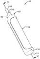
图1A和图1B是根据一个实施例的分别处于第一状态和第二状态的流体收集组件的等距视图。1A and 1B are isometric views of a fluid collection assembly in a first state and a second state, respectively, according to one embodiment.
图1C是根据一个实施例的如图1B所示的流体收集组件在第二状态下的示意性横截面图。Figure 1C is a schematic cross-sectional view of the fluid collection assembly shown in Figure IB in a second state, according to one embodiment.
图2A至2F是根据一个实施例的使用流体收集组件的方法的示意图。2A-2F are schematic diagrams of a method of using a fluid collection assembly, according to one embodiment.
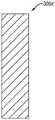
图3A至图3D是根据不同实施例的可用于本文公开的任意流体收集组件中的不同的一次性使用的芯吸筒的剖视图。3A-3D are cross-sectional views of various single-use wicking cartridges that may be used in any of the fluid collection assemblies disclosed herein, according to various embodiments.
图4A和图4B是根据不同实施例的具有不同标记的处于第一状态下的不同流体收集组件的等距视图。4A and 4B are isometric views of different fluid collection assemblies in a first state with different markings, according to different embodiments.
图5A和图5B是根据不同实施例的管的入口的等距视图,该管上形成有一个或多个槽。5A and 5B are isometric views of an inlet of a tube having one or more grooves formed thereon, according to various embodiments.
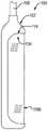
图6是根据一个实施例的流体收集组件的示意性横截面图,该流体收集组件配置为从男性尿道接收尿液。6 is a schematic cross-sectional view of a fluid collection assembly configured to receive urine from a male urethra, according to one embodiment.
图7是根据一个实施例的包括流体收集组件的系统的示意图。7 is a schematic diagram of a system including a fluid collection assembly, according to one embodiment.
具体实施方式Detailed ways
本文公开了流体收集组件、使用流体收集组件的方法以及包括流体收集组件的系统。示例性的流体收集组件包括:可重复使用的流体不可渗透阻挡件,其配置为是可重复使用的;以及至少一个一次性使用的芯吸筒,其可以不配置为是可重复使用的。在可重复使用的流体不可渗透阻挡件中限定有腔室。可重复使用的流体不可渗透阻挡件和一次性使用的芯吸筒配置为使得该一次性使用的芯吸筒设置在由该可重复使用的流体不可渗透阻挡件限定的腔室中。流体收集组件还可以包括至少一个管,该至少一个管至少部分地设置在腔室中或者以其他方式与腔室流体连通。该管配置为从该腔室移除其他体液(例如,尿液)。应该注意,该管也可形成包括流体收集组件的系统的一部分。Disclosed herein are fluid collection assemblies, methods of using fluid collection assemblies, and systems including fluid collection assemblies. Exemplary fluid collection assemblies include: a reusable fluid impermeable barrier that is configured to be reusable; and at least one disposable wicking cartridge that may not be configured to be reusable. A chamber is defined in the reusable fluid impermeable barrier. The reusable fluid-impermeable barrier and the single-use wicking cartridge are configured such that the single-use wicking cartridge is disposed within the chamber defined by the reusable fluid-impermeable barrier. The fluid collection assembly may also include at least one tube disposed at least partially within the chamber or otherwise in fluid communication with the chamber. The tube is configured to remove other bodily fluids (eg, urine) from the chamber. It should be noted that the tube may also form part of a system including a fluid collection assembly.
该流体收集组件配置为在第一状态和第二状态之间转换。当该流体收集组件处于第一状态时,一次性使用的芯吸筒没有设置在(例如,与之间隔开)可重复使用的流体不可渗透阻挡件的腔室中(图1A)。在一个实施例中,当一次性使用的芯吸筒最初没有设置在腔室中、与可重复使用的流体不可渗透阻挡件分开包装等时,流体收集组件可以最初处于第一状态(例如,在使用流体收集组件之前)。在一个实施例中,在使用过的一次性使用的芯吸筒从可重复使用的流体不可渗透阻挡件移除之后以及在未使用过的一次性使用的芯吸筒定位在腔室中之前,流体收集组件可以处于第一状态。The fluid collection assembly is configured to transition between a first state and a second state. When the fluid collection assembly is in the first state, the single-use wicking cartridge is not disposed (eg, spaced apart therefrom) within the chamber of the reusable fluid-impermeable barrier (FIG. 1A). In one embodiment, the fluid collection assembly may be initially in a first state (eg, at before using the fluid collection assembly). In one embodiment, after the used single-use wicking cartridge is removed from the reusable fluid-impermeable barrier and before the unused single-use wicking cartridge is positioned in the chamber, The fluid collection assembly may be in the first state.
当一次性使用的芯吸筒设置在腔室中时,流体收集组件处于第二状态(图1B)。至少当流体收集组件在使用中时,流体收集组件可以处于第二状态。流体收集组件可以使用在流体收集组件设置在邻近女性使用者的尿道开口的情况。在一个实施例中,在使用流体收集组件之前,流体收集组件在一段时间处于第二状态。在这样的实施例中,在使用流体收集组件之前,一次性使用的芯吸筒可以包装在可重复使用的流体不可渗透阻挡件的腔室中或者以其他方式设置在腔室中。在一个实施例中,在使用流体收集组件之后,流体收集组件在一段时间处于第二状态。然而,一般地,在出于卫生原因使用流体收集组件之后,流体收集组件仅在短时间(例如,几分钟或更短时间)处于第二状态。When the single-use wicking cartridge is disposed in the chamber, the fluid collection assembly is in the second state (FIG. IB). The fluid collection assembly may be in the second state at least when the fluid collection assembly is in use. The fluid collection assembly may be used where the fluid collection assembly is positioned adjacent the opening of the female user's urethra. In one embodiment, the fluid collection assembly is in the second state for a period of time prior to use of the fluid collection assembly. In such an embodiment, the single-use wicking cartridge may be packaged or otherwise disposed in the chamber of the reusable fluid-impermeable barrier prior to use of the fluid collection assembly. In one embodiment, the fluid collection assembly is in the second state for a period of time after use of the fluid collection assembly. Typically, however, the fluid collection assembly is only in the second state for a short time (eg, minutes or less) after the fluid collection assembly is used for hygienic reasons.
为了使流体收集组件在第一状态和第二状态之间转换,可重复使用的流体不可渗透阻挡件可在第一配置和第二配置之间转换。当可重复使用的流体不可渗透阻挡件处于第一配置时,可重复使用的流体不可渗透阻挡件可防止一次性使用的芯吸筒在一次性使用的芯吸筒在腔室外时被插入腔室中,和/或可防止一次性使用的芯吸筒在一次性使用的芯吸筒在腔室中时从腔室中移除。当可重复使用的流体不可渗透阻挡件处于第二配置时,一次性使用的芯吸筒可被插入腔室和/或从腔室中移除。To convert the fluid collection assembly between the first state and the second state, the reusable fluid-impermeable barrier is convertible between the first configuration and the second configuration. When the reusable fluid-impermeable barrier is in the first configuration, the reusable fluid-impermeable barrier prevents the single-use wicking cartridge from being inserted into the chamber while the single-use wicking cartridge is outside the chamber and/or may prevent the single-use wicking cartridge from being removed from the chamber while the single-use wicking cartridge is in the chamber. When the reusable fluid-impermeable barrier is in the second configuration, the single-use wicking cartridge can be inserted into and/or removed from the chamber.
在一个实施例中,将可重复使用的流体不可渗透阻挡件在第一配置和第二配置之间转换包括改变可重复使用的流体不可渗透阻挡件的开口的尺寸。例如,当可重复使用的流体不可渗透阻挡件处于第一配置时,可重复使用的流体不可渗透阻挡件的开口关闭或太小,使得一次性使用的芯吸筒不能穿过,而当可重复使用的流体不可渗透阻挡件处于第二配置时,可重复使用的流体不可渗透阻挡件的开口足够大,使得一次性使用的芯吸筒能够穿过。在一个示例中,通过弯曲、伸缩或以其他方式改变可重复使用的流体不可渗透阻挡件的形状,可重复使用的流体不可渗透阻挡件在第一配置和第二配置之间转换(例如,可重复使用的流体不可渗透阻挡件的开口在尺寸上发生改变)。In one embodiment, converting the reusable fluid-impermeable barrier between the first configuration and the second configuration includes changing the size of the opening of the reusable fluid-impermeable barrier. For example, when the reusable fluid-impermeable barrier is in the first configuration, the opening of the reusable fluid-impermeable barrier is closed or too small for a single-use wicking cartridge to pass through, and when the reusable fluid-impermeable barrier is in the first configuration, the opening of the reusable fluid-impermeable barrier is closed or too small When the fluid-impermeable barrier is used in the second configuration, the opening of the reusable fluid-impermeable barrier is large enough to allow a single-use wicking cartridge to pass through. In one example, the reusable fluid-impermeable barrier is converted between the first configuration and the second configuration by bending, stretching, or otherwise changing the shape of the reusable fluid-impermeable barrier (eg, may The openings of the fluid-impermeable barriers that are reused vary in size).
配置流体收集组件使其在第一状态和第二状态之间转换,以允许可重复使用的流体不可渗透阻挡件被重复使用,诸如与多个一次性使用的芯吸筒一起使用可重复使用的流体不可渗透阻挡件。例如,可重复使用的流体不可渗透阻挡件通常由硅酮、其他热固性聚合物、其他类型的聚合物或它们的组合形成。在这样的示例中,可重复使用的流体不可渗透阻挡件可能导致与它的低生物降解性和用于形成可重复使用的流体不可渗透阻挡件的稀有自然资源有关的若干环境问题。然而,重复使用可重复使用的流体不可渗透阻挡件降低了使用可重复使用的流体不可渗透阻挡件的环境影响,例如通过减少在使用流体收集组件时产生的废物量。这还降低了使用流体收集组件的成本。Configuring the fluid collection assembly to switch between the first state and the second state to allow the reusable fluid impermeable barrier to be reused, such as with a plurality of disposable wicking cartridges Fluid impermeable barrier. For example, reusable fluid-impermeable barriers are typically formed from silicone, other thermoset polymers, other types of polymers, or combinations thereof. In such an example, the reusable fluid impermeable barrier may cause several environmental issues related to its low biodegradability and the scarce natural resources used to form the reusable fluid impermeable barrier. However, reusing the reusable fluid impermeable barrier reduces the environmental impact of using the reusable fluid impermeable barrier, for example by reducing the amount of waste generated when the fluid collection assembly is used. This also reduces the cost of using the fluid collection assembly.
在一个实施例中,可重复使用的流体不可渗透阻挡件可以仅伴随同一个体重复使用。例如,可重复使用的流体不可渗透阻挡件可以伴随同一个体使用,并且可以伴随该个体使用时接收一个以上(例如,多个)一次性使用的芯吸筒。然而,一旦该个体对该流体收集组件的使用结束,那么该可重复使用的流体不可渗透阻挡件被丢弃。在一个实施例中,可重复使用的流体不可渗透阻挡件可伴随多个个体使用。在这样的实施例中,可重复使用的流体不可渗透阻挡件可以伴随第一个体使用,并且可以在被第一个体使用时接收一个以上(例如,多个)一次性使用的芯吸筒。一旦使用第一个体对该流体收集组件的使用结束,例如用消毒液(例如,抗菌清洁剂、抗微生物清洁剂或防腐剂清洁剂中的至少一种)和/或用高压灭菌器清洗可重复使用的流体不可渗透阻挡件。因为可重复使用的流体不可渗透阻挡件由硅酮或其他高温材料形成,所以清洗可重复使用的流体不可渗透阻挡件不会损坏该可重复使用的流体不可渗透阻挡件。然后该可重复使用的流体不可渗透阻挡件可以伴随第二个体使用。应当注意,当可重复使用的流体不可渗透阻挡件仅伴随单一个体使用时,例如当可重复使用的流体不可渗透阻挡件长时间伴随单一个体使用,并且例如可重复使用的流体不可渗透阻挡件中的微生物的生长成为关注的问题时,可重复使用的流体不可渗透阻挡件可以被清洗。In one embodiment, the reusable fluid-impermeable barrier can only be reused with the same individual. For example, a reusable fluid-impermeable barrier can be used with the same individual, and can receive more than one (eg, multiple) single-use wicking cartridges as used with the individual. However, once the individual's use of the fluid collection assembly is over, the reusable fluid impermeable barrier is discarded. In one embodiment, the reusable fluid impermeable barrier can be used with multiple individuals. In such embodiments, the reusable fluid-impermeable barrier may be used with the first individual and may receive one or more (eg, multiple) single-use wicking cartridges when used by the first individual . Once use of the fluid collection assembly with the first individual is complete, cleaning, eg, with a disinfectant (eg, at least one of an antibacterial, antimicrobial, or antiseptic cleaner) and/or with an autoclave Reusable fluid impermeable barrier. Because the reusable fluid impermeable barrier is formed of silicone or other high temperature material, cleaning the reusable fluid impermeable barrier will not damage the reusable fluid impermeable barrier. The reusable fluid-impermeable barrier can then be used with a second individual. It should be noted that when the reusable fluid-impermeable barrier is used with only a single individual, such as when the reusable fluid-impermeable barrier is used with a single individual for an extended period of time, and such as in the reusable fluid-impermeable barrier When microbial growth becomes a concern, reusable fluid-impermeable barriers can be cleaned.
图1A和图1B是根据一个实施例的分别处于第一状态(即,一次性使用的芯吸筒106未设置在可重复使用的流体不可渗透阻挡件102中)和第二状态(即,一次性使用的芯吸筒106设置在可重复使用的流体不可渗透阻挡件102中)的流体收集组件100的等距视图。流体收集组件100包括:可重复使用的流体不可渗透阻挡件102,其限定腔室104;一次性使用的芯吸筒106;并且可选地包括:与腔室104流体连通的至少一个管108。腔室104和一次性使用的芯吸筒106的尺寸和形状允许一次性使用的芯吸筒106设置在腔室104中。换句话说,腔室104和一次性使用的芯吸筒106的尺寸和形状(例如,垂直于流体收集组件100的纵向轴线的横截面的尺寸和形状)通常彼此对应。FIGS. 1A and 1B are respectively in a first state (ie, the single-
可重复使用的流体不可渗透阻挡件102在第一端110和相对的第二端112之间纵向延伸。可重复使用的流体不可渗透阻挡件102限定至少一个开口114,该至少一个开口114位于第一端110和第二端112之间。开口114配置为定位在邻近女性尿道开口处,并且配置为当开口114定位在邻近女性尿道开口处时允许女性尿道开口与腔室104流体连通。例如,由女性尿道开口排出的体液(例如尿液)经由开口114进入腔室104。The reusable fluid
一般地,开口114沿着可重复使用的流体不可渗透阻挡件102的长度的显著部分(例如,至少20%、至少50%、至少75%、20%至60%、50%至75%或60%至90%)延伸,以增加进入腔室104的流体的量。在一个示例中,开口114包括细长开口。在一个示例中,开口114包括多个狭缝。Typically, the
在一个实施例中,如上文讨论的,开口114可以配置为改变开口114的尺寸,从而允许可重复使用的流体不可渗透阻挡件102在第一配置和第二配置之间转换。例如,如图1A和图1B所示,可重复使用的流体不可渗透阻挡件102处于第一配置,因为开口114不具有够大的尺寸以允许一次性使用的芯吸筒106插入腔室104或从腔室104中移除。然而,如将参照图2A至图2F更详细地讨论的,以弯曲或以其他方式改变(例如,伸缩)可重复使用的流体不可渗透阻挡件102可以增加开口114的尺寸,使得一次性使用的芯吸筒106可以插入腔室104或从腔室104中移除。在一个实施例中,开口114可以不被配置为改变尺寸。在这样的实施例中,可重复使用的流体不可渗透阻挡件102可以包括另一个开口(未图示),例如形成在第一端110中的开口,该开口配置为改变尺寸。例如,当可重复使用的流体不可渗透阻挡件102处于第一配置时,形成在第一端110中的开口可被关闭,以防止流体通过形成在第一端110中的开口从腔室104泄漏。In one embodiment, as discussed above, the
可重复使用的流体不可渗透阻挡件102可以配置为以弯曲或以其他方式改变其形状,从而允许可重复使用的流体不可渗透阻挡件102在第一配置和第二配置之间转换。在一个实施例中,可重复使用的流体不可渗透阻挡件102的至少一部分可以由可弯曲和/或可伸缩的材料形成,例如硅酮或其他合适的聚合物,从而允许可重复使用的流体不可渗透阻挡件102弯曲和/或伸缩。在一个实施例中,可重复使用的流体不可渗透阻挡件102可以包括一个或多个铰链或其他机械装置,一个或多个铰链或其他机械装置允许可重复使用的流体不可渗透阻挡件102以弯曲或以其他方式改变其形状。The reusable fluid-
可重复使用的流体不可渗透阻挡件102可以配置为在特定位置以弯曲或以其他方式改变其形状。在一个实施例中,当开口114配置为改变尺寸时,特定位置(即,配置为以弯曲或以其他方式改变其形状的可重复使用的流体不可渗透阻挡件102的部分)位于更靠近第一端110而非第二端112的位置。选择更靠近第一端110而非第二端112的特定位置可以使得在一次性使用的芯吸筒106定位在腔室104中时更容易围绕一次性使用的芯吸筒106的第一末端121操纵第一端110,并且更容易围绕管108定位一次性使用的芯吸筒106。在一个示例中,特定位置可以比可重复使用的流体不可渗透阻挡件102的至少一部分更易弯曲(例如,柔软、可伸缩、较低刚性),该可重复使用的流体不可渗透阻挡件102的至少一部分位于特定位置和第二端112之间,这使得可重复使用的流体不可渗透阻挡件102在特定位置处优先以弯曲或以其他方式改变其形状。例如,该特定位置可以包括减薄区域120(如图1C所示),减薄区域120的厚度小于位于特定位置和第二端112之间的可重复使用的流体不可渗透阻挡件102的至少一部分的厚度。可选地或除了减薄区域120之外,特定位置可以包括由该特定位置限定的缺口、由该特定位置限定的凹部、形成在该特定位置中的缝,特定位置可以包括比可重复使用的流体不可渗透阻挡件102的其余部分更易弯曲的材料,或引起特定位置优先以弯曲或以其他方式改变其形状的任何其他合适机构。应该注意的是,第一端110和/或在特定位置和第一端110之间的可重复使用的流体不可渗透阻挡件102的部分可以比在特定位置和第二端112之间的可重复使用的流体不可渗透阻挡件102的至少一部分更易弯曲(例如,与特定位置相同或略小的弯曲能力),以有助于围绕一次性使用的芯吸筒106的第一末端121操纵第一端110。The reusable fluid-
可重复使用的流体不可渗透阻挡件102还限定出口116,例如在可重复使用的流体不可渗透阻挡件102的第二端112处。出口116配置为连接至管108和/或具有设置在出口116中的管108。这样,出口116允许管108与腔室104流体连通。在所示的实施例中,管108也设置在腔室104中。在这样的实施例中,管108可以定位在基本上空置的流体储存器118处或附近(如图1C所示),这有助于移除存在于流体储存器118中的任何流体(例如,尿液)。The reusable fluid-
参考图1A,一次性使用的芯吸筒106包括第一末端121、与第一末端121相对的第二末端122、以及在第一末端121和第二末端122之间延伸的至少一个外表面124。一次性使用的芯吸筒10配置为,当定位在腔室104中时,接收流体并且芯吸流体使流体远离开口114。例如,一次性使用的芯吸筒106可以配置为(特别是在存在吸力的情况下)芯吸流体使流体朝向管108的入口,使得流体可以从腔室104中移除。因此,一般地,一次性使用的芯吸筒106由允许流体从中流过的多孔材料形成。一次性使用的芯吸筒106由可以接收(例如,吸收、吸附或芯吸)流体的任何合适的材料(例如,棉纱)形成。然而,一次性使用的芯吸筒106由配置为主要芯吸(而不是主要吸收或吸附)流体的材料形成。可以主要芯吸材料的示例包括尼龙(例如,纺尼龙纤维)或聚烯烃。在一个实施例中,一次性使用的芯吸筒106由无纺材料(例如,无纺纤维)形成,无纺材料可以有助于通过挤出工艺形成一次性使用的芯吸筒106。Referring to FIG. 1A , the
在一个实施例中,一次性使用的芯吸筒106可以包括设计成芯吸流体或使流体从中流过的可渗透材料。本文所指的可渗透性质可以是芯吸、毛细管作用、扩散或其他类似的性质或过程,并且在本文中称为“可渗透”和/或“芯吸”。这种“芯吸”可以不包括将流体吸收到芯吸材料中。换句话说,在材料暴露于流体并从流体移除一段时间之后,基本上不会发生流体吸收到材料中。虽然不需要吸收,但是术语“基本上不吸收”可允许标称量的流体吸收到芯吸材料中(例如,吸收性),例如小于芯吸材料干重的约10wt%、小于芯吸材料干重的约7wt%、小于芯吸材料干重的约5wt%、小于芯吸材料干重的约3wt%、小于芯吸材料干重的约2wt%、小于芯吸材料干重的约1wt%、或小于芯吸材料干重的约0.5wt%。In one embodiment, the single-
芯吸材料可以包括天然纤维。在这样的示例中,材料可以具有防止或限制流体吸收到材料中的涂层,例如防水涂层。The wicking material may include natural fibers. In such an example, the material may have a coating that prevents or limits the absorption of fluids into the material, such as a water repellent coating.
在使用期间,一次性使用的芯吸筒106可在一段时间期间接收来自个体的体液,如将在下文更详细地讨论的。在使用之后,一次性使用的芯吸筒106从流体不可渗透阻挡件102移出并丢弃。一次性使用的芯吸筒106可以不重复使用,因为一次性使用的芯吸筒106需要清洁才能重复使用。清洁一次性使用的芯吸筒106包括从一次性使用的芯吸筒的所有表面去除所有体液并进行消毒。然而,一次性使用的芯吸筒的多孔性使得去除所有体液和对一次性使用的芯吸筒的所有表面进行消毒是困难且昂贵的。此外,由于需要从一次性使用的芯吸筒的所有表面去除所有体液并进行消毒的极端清洁措施,清洁一次性使用的芯吸筒可能会损坏一次性使用的芯吸筒106并增加一次性使用的芯吸筒106的体积。一次性使用的芯吸筒106的增大的体积可能会妨碍一次性使用的芯吸筒106插入腔室104中。During use, the single-
当管108设置在腔室104中时,一次性使用的芯吸筒106限定至少一个通道126,该通道126至少部分地延伸穿过一次性使用的芯吸筒106。例如,第二末端122限定通道126的入口(未图示,遮挡)。通道126的尺寸和形状允许通道126接收管108(例如,通道126的尺寸和形状对应于或略大于管108)。通道126的长度取决于延伸至腔室104中的管108的长度。尤其地,一般地,通道126的长度等于或大于延伸至腔室104中的管108的一部分的长度。在一个实施例中,通道126仅部分地延伸通过一次性使用的芯吸筒106。在一个实施例中,如图所示,通道126完全延伸通过一次性使用的芯吸筒106,使得第一末端121部分地限定通道126的相对入口。The single-
外表面124和一次性使用的芯吸筒106作为整体可以具有任何合适的形状。例如,外表面124和一次性使用的芯吸筒106作为整体可以具有大致圆柱形的形状(如图所示)、大致箱形的形状(例如,细长的大致箱形的形状)、大致三棱柱的形状(例如,细长的大致棱柱的形状)、弯曲的形状(例如,弯曲的大致圆柱形的形状)或任何其他合适的形状。然而,外表面124和一次性使用的芯吸筒106的形状和尺寸可以取决于腔室104的尺寸和形状。例如,图1C是根据一个实施例的如图1B所示的流体收集组件100在第二状态下的示意性横截面图。可重复使用的流体不可渗透阻挡件102包括至少一个内表面128,该至少一个内表面128部分地限定腔室104。可重复使用的流体不可渗透阻挡件102的内表面128的至少一部分和一次性使用的芯吸筒106的外表面124的相应部分被选择为具有彼此对应的横截面形状(垂直于可重复使用的流体不可渗透阻挡件102的纵向轴线和一次性使用的芯吸筒106的平行轴线测量)。当一次性使用的芯吸筒106的外表面124的横截面形状在尺寸上等于、略大于(例如至多大10%、至少至多大5%或至多大2%)、或略小于(例如至多小10%、至少至多小5%或至多小2%)可重复使用的流体不可渗透阻挡件102的内表面128的横截面形状时,内表面128和外表面124的横截面形状彼此对应。这种横截面形状抑制在可重复使用的流体不可渗透阻挡件102的内表面128和一次性使用的芯吸筒106的外表面124之间形成大的空气间隙,该空气间隙会导致流体积聚和/或抑制流体朝向管108的流动。此外,这种横截面形状允许一次性使用的芯吸筒106容易地插入腔室104插入和/或从腔室104中移除,因为当流体收集组件100处于第二状态时,至多地,一次性使用的芯吸筒106仅被轻微地压配合到可重复使用的流体不可渗透阻挡件102中。The
在一个实施例中,一次性使用的芯吸筒106的长度可以小于腔室104的长度。在这样的实施例中,流体收集组件100可以限定在可重复使用的流体不可渗透阻挡件102的第一端110处和/或附近的第一间隙130或可重复使用的流体不可渗透阻挡件102的第二端112处和/或附近的第二间隙132中的至少一者。第一间隙130和/或第二间隙132可有助于流体收集组件100的操作。例如,第一间隙130可以在可重复使用的流体不可渗透阻挡件102的第一端110处和/或附近形成基本上未被占用的间隙。因为在操作中,第一端110趋向于是流体收集组件100的低点,所以流体很可能在经由管108从腔室104移除之前收集在第一间隙130中。这样,第一间隙130形成流体储存器118的一部分。此外,当将可重复使用的流体不可渗透阻挡件102在它的第一配置和第二配置之间转换时,第一间隙130使得更容易围绕一次性使用的芯吸筒106的第一末端121操纵可重复使用的流体不可渗透阻挡件102的第一端110。In one embodiment, the length of the single-
此外,如图1C所示,在可重复使用的流体不可渗透阻挡件102的第二端112处和/或附近的腔室104通常例如朝向出口116逐渐变细(例如,内表面128的直径减小)。一次性使用的芯吸筒106可以不具有类似逐渐变细的形状,因为例如一次性使用的芯吸筒106可以通过挤压形成。因此,使一次性使用的芯吸筒106具有小于腔室104的长度(由此形成第二间隙132)表示一次性使用的芯吸筒106不必插入或完全插入腔室104的逐渐变细的部分中。因此,在一次性使用的芯吸筒106不是类似逐渐变细时,第二间隙132防止一次性使用的芯吸筒106的第二末端122被腔室104的逐渐变细的部分压缩。例如,压缩一次性使用的芯吸筒106的第二末端可阻止一次性使用的芯吸筒106容易地插入到腔室104中和/或从腔室104中移除。Furthermore, as shown in FIG. 1C , the
图2A至图2F是根据一个实施例的使用流体收集组件的方法的示意图。图2A至图2F中所示的流体收集组件是图1A至图1C中所示的流体收集组件100。然而,应该注意,图2A至图2F示出的方法可以与本文公开的任意流体收集组件一起使用。2A-2F are schematic diagrams of a method of using a fluid collection assembly, according to one embodiment. The fluid collection assembly shown in FIGS. 2A-2F is the
参考图2A,提供流体收集组件100。流体收集组件100包括可重复使用的流体不可渗透阻挡件102和第一一次性使用的芯吸筒106a。在一个实施例中,如图所示,流体收集组件100设置在第二状态,即第一一次性使用的芯吸筒106a设置在由可重复使用的流体不可渗透阻挡件102限定的腔室104中(如图2C至图2D所示)。然而,在一个实施例中,流体收集组件100可以最初设置在第一状态,即第一一次性使用的芯吸筒106a最初与腔室104间隔开。在这样的实施例中,该方法包括将第一一次性使用的芯吸筒106a插入到可重复使用的流体不可渗透阻挡件102中,如图2D至图2F所示。Referring to Figure 2A, a
流体收集组件100最初可以在第一一次性使用的芯吸筒106a处于未使用状态(例如,第一一次性使用的芯吸筒106a没有接收任何流体)时提供。然后,流体收集组件100可以定位成使得开口114邻近尿道开口(例如,所示的流体收集组件100的开口114配置成邻近女性尿道开口),从而允许第一一次性使用的芯吸筒106a接收来自尿道开口的体液。从尿道开口接收体液导致第一一次性使用的芯吸筒106a处于使用状态。在一个实施例中,例如在第一一次性使用的芯吸筒106a处于使用状态之后或者在第一一次性使用的芯吸筒106a最初进入使用状态之后的某个时间,第一一次性使用的芯吸筒106a可以从腔室104中移除。在一个实施例中,出于卫生的原因和/或减少流体在第一一次性使用的芯吸筒106a中沉积的残留材料造成的堵塞,在将开口114定位在邻近尿道开口处之后的某个预定时间,第一一次性使用的芯吸筒106a从腔室104中移除。该预定时间可以是至少约1小时、至少约2小时、至少约4小时、至少约6小时、至少约8小时、至少约10小时、至少约12小时、至少约14小时、至少约16小时、至少约18小时、至少约20小时、至少约22小时、至少约24小时,或者在约1小时至约4小时的范围内、在约2小时至约6小时的范围内、在约4小时至约8小时的范围内、在约6小时至约10小时的范围内、在约8小时至约12小时的范围内、在约10小时至约14小时的范围内、在约12小时至约16小时的范围内、在约14小时至约18小时的范围内、在约16小时至约20小时的范围内、在约18小时至约22小时的范围内,或在约20小时至约24小时的范围内。The
图2B和图2C示出了如何将第一一次性使用的芯吸筒106a从腔室104中移除。参考图2B,可重复使用的流体不可渗透阻挡件102从第一配置转换为第二配置。在所示实施例中,通过弯曲位于第一端110上或附近的可重复使用的流体不可渗透阻挡件102的一部分以及围绕第一一次性使用的芯吸筒106a的第一末端121a操纵第一端部110,可重复使用的流体不可渗透阻挡件102从第一配置转换为第二配置。一旦可重复使用的流体不可渗透阻挡件102处于第二配置,第一一次性使用的芯吸筒106a可以沿着管108滑动(如果管108设置在腔室104中)并且容易地从腔室104中移除,如图2C所示。第一一次性使用的芯吸筒106a可以以任何合适的方式处置。FIGS. 2B and 2C illustrate how the first single-
参考图2D,如果可重复使用的流体不可渗透阻挡件102被重复使用,则第二一次性使用的芯吸筒106b可定位在腔室104中。例如,可以提供处于未使用状态的第二一次性使用的芯吸筒106b。第二一次性使用的芯吸筒106b可以与本文公开的任何一次性使用的芯吸筒相同或基本相似(例如,可以与第一一次性使用的芯吸筒106a相同或基本相似)。当可重复使用的流体不可渗透阻挡件102处于第二配置时,第二一次性使用的芯吸筒106b可以插入到腔室104中。例如,在所示的实施例中,通过将管108定位在由第二一次性使用的芯吸筒106b限定的通道(未图示)中,然后使第二一次性使用的芯吸筒106b沿着管108滑动直到第二一次性使用的芯吸筒106b适当地定位到腔室104中,第二一次性使用的芯吸筒106b可以插入到腔室104中。Referring to FIG. 2D , if the reusable fluid-
一旦第二一次性使用的芯吸筒106b适当地定位到腔室104中,可重复使用的流体不可渗透阻挡件102从第二配置转换为第一配置。例如,在所示的实施例中,通过弯曲可重复使用的流体不可渗透阻挡件102以及围绕第二一次性使用的芯吸筒106b的第一末端121b操纵可重复使用的流体不可渗透阻挡件102的第一端110,可重复使用的流体不可渗透阻挡件102可以从第一配置转换为第二配置,如图2E所示。然后,完全组装的流体收集组件100准备好使用(例如,流体收集组件100的开口114准备好被定位在尿道开口附近),如图2F所示。Once the second single-
应当注意,该方法可以包括图2A至图2F中未示出的额外步骤。例如,该方法可以包括在图2C至图2D所示的动作之间清洗可重复使用的流体不可渗透阻挡件102。清洗可重复使用的流体不可渗透阻挡件102可以包括仅冲洗可重复使用的流体不可渗透阻挡件,以在移除第一一次性使用的芯吸筒106a之后去除可能残留在可重复使用的流体不可渗透阻挡件102上的流体中的至少一些,和/或可以包括至少部分地对可重复使用的流体不可渗透阻挡件102进行消毒。对可重复使用的流体不可渗透阻挡件102进行消毒可以包括用消毒液(例如,抗菌肥皂)清洗可重复使用的流体不可渗透阻挡件102或对可重复使用的流体不可渗透阻挡件102进行高压灭菌。It should be noted that the method may include additional steps not shown in Figures 2A-2F. For example, the method may include cleaning the reusable fluid-
在一个实施例中,图2A至图2F所示的方法可以根据需要重复多次。例如,图2A至图2F所示的方法可以重复,以移除第二一次性使用的芯吸筒106b并添加额外的一次性使用的芯吸筒。此外,图2A至图2F所示的方法可以重复,以移除额外的的一次性使用的芯吸筒等。In one embodiment, the method shown in FIGS. 2A-2F may be repeated as many times as necessary. For example, the method shown in FIGS. 2A-2F may be repeated to remove the second single-
图3A至图3D是根据不同实施例的可用于本文公开的任意流体收集组件中的不同的一次性使用的芯吸筒的横截面图。除非本文另有公开,图3A至图3D所示的一次性使用的芯吸筒与本文公开的任意一次性使用的芯吸筒(包括彼此)相同或基本相似。例如,一次性使用的芯吸筒可以包括第一末端、相对的第二末端、在第一末端和第二末端之间延伸的外表面,以及可选地,包括通道。3A-3D are cross-sectional views of various single-use wicking cartridges that may be used in any of the fluid collection assemblies disclosed herein, according to various embodiments. Unless otherwise disclosed herein, the single-use wicking cartridges shown in FIGS. 3A-3D are identical or substantially similar to any single-use wicking cartridges disclosed herein, including each other. For example, a single-use wicking cartridge may include a first end, an opposing second end, an outer surface extending between the first end and the second end, and, optionally, a channel.
参考图3A,一次性使用的芯吸筒306a由单个部件形成(例如,是一体的)并且限定通道326a。一次性使用的芯吸筒306a的厚度沿着一次性使用的芯吸筒306a的整个长度基本是均匀的。一次性使用的芯吸筒306a具有基本均匀的厚度,因为一次性使用的芯吸筒306a使用挤出工艺形成。然而,应当注意,一次性使用的芯吸筒306a可以使用除了挤出工艺之外的任何合适的方法形成,例如轧制多孔材料的片材并且将片材的相对端粘合(例如,用粘合剂)在一起。还应该注意,本文公开的任意一次性使用的芯吸筒可以具有不均匀的厚度。Referring to Figure 3A, a single-
参考图3B,一次性使用的芯吸筒306b由两个以上部件形成。例如,一次性使用的芯吸筒306b可以包括流体可渗透支撑件334和流体可渗透膜336。流体可渗透支撑件334可以限定通道326b,并且可以将流体可渗透膜336支撑在通道326b上方。当流体可渗透膜336延伸穿过可重复使用的流体不可渗透阻挡件的开口时,流体可渗透支撑件334也可以支撑流体可渗透膜336。在一个实施例中,流体可渗透膜336被选择为比流体可渗透支撑件334更舒适地抵靠女性尿道。在一个实施例中,流体可渗透支撑件334被选择为比流体可渗透膜336更好地芯吸流体(例如,吸收性或吸附性更差)。在任一实施例中,流体可渗透膜336可选择为纱布或布,流体可渗透支撑件334可选择为纺尼龙纤维和/或聚烯烃。应当注意,流体可渗透膜336可以包括纱布或布之外的材料,流体可渗透支撑件334可以包括除纺尼龙纤维或聚烯烃之外的材料,这些材料仅作为示例提供。Referring to Figure 3B, a single-
一次性使用的芯吸筒306b还可以包括粘合剂层338,该粘合剂层338处于流体可渗透支撑件334的至少一部分与流体可渗透膜336的相应部分之间。当一次性使用的芯吸筒306b被插入腔室和/或从腔室中移除时,粘合剂层338维持流体可渗透支撑件334和流体可渗透膜336相对于彼此的位置。例如,在没有粘合剂层338的情况下,流体可渗透支撑件334和流体可渗透膜336可能易于相对彼此移动,这使得一次性使用的芯吸筒306b的插入和/或移除更加困难。此外,允许流体可渗透支撑件334和流体可渗透膜336相对于彼此移动可能会形成不期望的空气间隙,空气间隙可以允许流体积聚和滞留。The single-
一次性使用的芯吸筒306b可以使用任何合适的方法形成。在一个示例中,一次性使用的芯吸筒306b可以使用双挤压工艺形成。在一个示例中,一次性使用的芯吸筒306b可以通过轧制或挤压流体可渗透支撑件334,然后将流体可渗透膜336围绕流体可渗透支撑件334定位来形成。形成一次性使用的芯吸筒306的方法还可以包括将粘合剂施加到流体可渗透支撑件334的外表面的至少一部分,并且将流体可渗透膜336围绕流体可渗透支撑件334定位还包括将流体可渗透膜336围绕粘合剂层338定位。The single-
参考图3C,一次性使用的芯吸筒306c限定通道326c,该通道326c仅部分延伸穿过一次性使用的芯吸筒306c。当例如管(例如图1A的管108)不延伸至或靠近流体储存器时,通道326c可以仅部分地延伸穿过一次性使用的芯吸筒306c。在一个实施例中,管可以仅部分地延伸穿过一次性使用的芯吸筒306c,因为例如当管完全延伸穿过一次性使用的芯吸筒306c时,管可能妨碍将可重复使用的流体不可渗透阻挡件在第一配置和第二配置之间转换。使管仅部分地延伸穿过一次性使用的芯吸筒306c可导致管与流体收集组件的流体储存器(例如,图1C中所示的流体储存器118)间隔开,这可以抑制管接收流体。为了解决这个问题,一次性使用的芯吸筒306c可以包括多孔部分,该多孔部分定位在通道326c和一次性使用的芯吸筒306b的第一末端321(“多孔部分”)之间。多孔部分可以配置为将流体从第一末端321(例如,从流体储存器)芯吸到通道326c,从而允许管接收存在于流体储存器中的流体。Referring to Figure 3C, the single-
在一个实施例中,一次性使用的芯吸筒306c的多孔部分与一次性使用的芯吸筒306c的至少一个其他部件一体地形成。然而,根据用于形成一次性使用的芯吸筒306c的方法,与一次性使用的芯吸筒306c的至少一个其他部件一体地形成的多孔部分可能难以形成。例如,一次性使用的芯吸筒306c当通过挤出工艺形成时,与一次性使用的芯吸筒306c的至少一个其他部件一体地形成的多孔部分可能难以形成。这样,在一个实施例中,一次性使用的芯吸筒306c可以包括塞子340(例如,多孔部分是塞子340),该塞子340与一次性使用的芯吸筒306c的其余部分是不同的。塞子340可以定位成使得塞子340在通道326c和第一末端321之间延伸,并且塞子340将材料从第一末端321芯吸到通道326c。塞子340的尺寸可以允许塞子340插入通道326c中。塞子340可以由与一次性使用的芯吸筒306c的其余部分相同或不同的材料形成。在一个示例中,塞子340可以粘附到一次性使用的芯吸筒306c的其余部分。In one embodiment, the porous portion of the single-
参考图3D,一次性使用的芯吸筒306d不限定通道。例如,当管不定位在腔室内或者仅延伸到腔室内一段较短距离(例如,仅延伸到图1C中所示的第二间隙132)时,一次性使用的芯吸筒306d不限定通道。Referring to Figure 3D, the single-
在一些实施例中,一次性使用的芯吸筒在可重复使用的流体不可渗透阻挡件中的正确定位可能是重要的。在一个示例中,将一次性使用的芯吸筒太远地插入可重复使用的流体不可渗透阻挡件中,可能出现以下情况中的至少一种:形成低效的大的第一间隙,这会导致流体的过度积聚和滞留;或者压缩靠近可重复使用的流体不可渗透阻挡件的第二端的一次性使用的芯吸筒的部分,这会使得一次性使用的芯吸筒的移除困难。在一个示例中,如果未能将单一使用芯吸筒完全插入到可重复使用的流体不可渗透阻挡件中,可能出现以下情况中的至少一种:防止流体储存器的形成;使可重复使用的流体不可渗透阻挡件难以在第一配置和第二配置之间转换;或者导致形成低效的大的第二间隙,这会导致流体的过度积聚和滞留。这样,本文公开的一次性使用的芯吸筒可以包括有助于一次性使用的芯吸筒的正确放置的一个或多个特征。In some embodiments, proper positioning of the single-use wicking cartridge in the reusable fluid-impermeable barrier may be important. In one example, inserting a single-use wicking cartridge too far into a reusable fluid-impermeable barrier may result in at least one of the following: creating an inefficient large first gap, which can cause Causes excessive accumulation and retention of fluid; or compresses the portion of the single-use wicking cartridge near the second end of the reusable fluid-impermeable barrier, which can make removal of the single-use wicking cartridge difficult. In one example, failing to fully insert the single-use wicking cartridge into the reusable fluid-impermeable barrier, at least one of the following may occur: prevent the formation of a fluid reservoir; enable the reusable Fluid impermeable barriers are difficult to transition between the first and second configurations; or result in the formation of inefficient large second gaps, which can lead to excessive accumulation and retention of fluid. As such, the single-use wicking cartridges disclosed herein may include one or more features that facilitate proper placement of the single-use wicking cartridge.
在一个实施例中,有助于一次性使用的芯吸筒在可重复使用的流体不可渗透阻挡件中的正确放置的特征包括形成在可重复使用的流体不可渗透阻挡件或一次性使用的芯吸筒的至少一个上的一个或多个标记。可重复使用的流体不可渗透阻挡件或一次性使用的芯吸筒中的一个上的标记可对应于可重复使用的流体不可渗透阻挡件或一次性使用的芯吸筒中的另一个上的特征(例如,其他标记)。图4A和图4B是根据不同实施例的具有不同标记的处于第一状态下的不同流体收集组件的等距视图。除非本文另有公开,图4A和图4B中所示的流体收集组件与本文公开的任意流体收集组件相同或基本相似。In one embodiment, features that facilitate proper placement of a single-use wicking cartridge in a reusable fluid-impermeable barrier include being formed in a reusable fluid-impermeable barrier or a single-use wick One or more markings on at least one of the suction cartridges. The indicia on one of the reusable fluid-impermeable barrier or the single-use wicking cartridge may correspond to features on the other of the reusable fluid-impermeable barrier or the single-use wicking cartridge (eg, , other marks). 4A and 4B are isometric views of different fluid collection assemblies in a first state with different markings, according to different embodiments. Unless otherwise disclosed herein, the fluid collection assemblies shown in FIGS. 4A and 4B are the same as or substantially similar to any of the fluid collection assemblies disclosed herein.
参考图4A,流体收集组件400a包括限定开口414a的可重复使用的流体不可渗透阻挡件402a。流体收集组件400a还包括一次性使用的芯吸筒406a。一次性使用的芯吸筒406a包括形成在其上的至少一个标记442a。标记442a可以包括线和/或阴影区域。标记442a可以呈现开口414a的至少一部分的形状。在所示的实施例中,标记442a呈现整个开口414a的形状。然而,应该注意,标记442a可以仅对应于开口414a的一部分。例如,标记442a可以仅对应于靠近第二端412的开口414a的部分,因为当可重复使用的流体不可渗透阻挡件402a处于第二配置时,靠近第一端410a的可重复使用的流体不可渗透阻挡件402a的部分可以弯曲或以其他方式变形。Referring to Figure 4A, the
参考图4B,流体收集组件400b包括可重复使用的流体不可渗透阻挡件402b和一次性使用的芯吸筒406b。可重复使用的流体不可渗透阻挡件402b包括第一标记442b,一次性使用的芯吸筒406b包括第二标记444。第一标记442b和第二标记444位于可重复使用的流体不可渗透阻挡件402b和一次性使用的芯吸筒406b的相应部分上,使得当第一标记442b和第二标记444对齐时,一次性使用的芯吸筒406b被正确定位。Referring to Figure 4B, the
为了便于正确定位一次性使用的芯吸筒406b,第一标记442b可以位于可重复使用的流体不可渗透阻挡件402b的开口414b附近。第一标记442b也可以定位在更靠近可重复使用的流体不可渗透阻挡件402b的第二端412b而非第一端410b的位置,使得弯曲或以其他方式修改可重复使用的流体不可渗透阻挡件402b的形状不太可能改变第一标记442b的位置。To facilitate proper positioning of the single-use wicking cartridge 406b, the
在一个实施例中,如图所示,第二标记444围绕一次性使用的芯吸筒406b的圆周延伸。这允许一次性使用的芯吸筒406b被正确定位,而不管一次性使用的芯吸筒406b的旋转。然而,应当注意,例如,当一次性使用的芯吸筒406b不能相对于可重复使用的流体不可渗透阻挡件402b自由旋转时,第二标记444可以不围绕一次性使用的芯吸筒406b的圆周延伸。In one embodiment, as shown, the
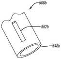
一次性使用的芯吸筒在腔室中的不当放置可以导致一次性使用的芯吸筒阻塞或以其他方式遮挡管的入口。在一个示例中,将一次性使用的芯吸筒太远地插入腔室中可能导致一次性使用的芯吸筒的多孔部分(例如,图中3C中所示的塞子340)阻塞或以其他方式遮挡管的入口。在一个示例中,未将一次性使用的芯吸筒足够远地插入腔室中会导致一次性使用的芯吸筒在一次性使用的芯吸筒的第一端部或附近聚成一团,这可能导致一次性使用的芯吸筒的某些通道塌陷,从而阻塞或以其他方式遮挡管的入口。堵塞或以其他方式遮挡管的入口可以劣化流体收集组件的功能性,因为堵塞或遮挡管的入口会减少或抑制流体流出腔室。为了缓和这个问题,管可以包括形成在管中的一个或多个狭槽,一个或多个狭槽不太可能被一次性使用的芯吸筒的不正确放置所堵塞或遮挡。图5A和图5B是根据不同实施例的管的入口的等距视图,该管上形成有一个或多个槽。图中5A至图5B所示的管可以用于本文公开的任意流体收集组件。Improper placement of the single-use wicking cartridge in the chamber can cause the single-use wicking cartridge to block or otherwise obstruct the access to the tube. In one example, inserting the single-use wicking cartridge too far into the chamber may cause a porous portion of the single-use wicking cartridge (eg, plug 340 shown in FIG. 3C ) to block or otherwise Block the entrance to the tube. In one example, not inserting the single-use wicking cartridge far enough into the chamber can cause the single-use wicking cartridge to clump at or near the first end of the single-use wicking cartridge, which Some channels of the single-use wicking cartridge may collapse, thereby blocking or otherwise obscuring the access to the tube. Blocking or otherwise blocking the inlet to the tube can degrade the functionality of the fluid collection assembly because blocking or blocking the access to the tube reduces or inhibits fluid flow out of the chamber. To alleviate this problem, the tube may include one or more slots formed in the tube that are less likely to be blocked or obstructed by improper placement of the single-use wicking cartridge. 5A and 5B are isometric views of an inlet of a tube having one or more grooves formed thereon, according to various embodiments. The tubes shown in Figures 5A-5B can be used with any of the fluid collection assemblies disclosed herein.
参考图5A,管508a限定在管508a的末端548a处的入口546和从末端548a延伸的至少一个壁550。管508a还限定从终端548a延伸任意合适距离的至少一个狭槽552a。应该注意,至少一个狭槽552a不必从终端548a延伸。例如,如图5B所示,管508b可以包括至少一个狭槽552b,该狭槽552b在终端548b上方间隔开。狭槽552b在终端548b上方间隔开可以降低狭槽552b被遮挡或者阻塞的可能性。Referring to Figure 5A,
关于以上公开的流体收集组件的特征和原理也可以应用于配置为从男性尿道开口(例如,阴茎)接收尿液的流体收集组件。例如,图6是根据一个实施例的流体收集组件600的示意性剖视图截图,该流体收集组件600配置为从男性尿道接收尿液。除非本文另有公开,流体收集组件600与本文公开的任意流体收集组件相同或基本相似。例如,流体收集组件600包括可重复使用的流体不可渗透阻挡件602,该可重复使用的流体不可渗透阻挡件602限定腔室604和一次性使用的芯吸筒606。流体收集组件600还可以包括至少一个管608,该至少一个管608与腔室604流体连通。Features and principles related to the fluid collection assemblies disclosed above may also be applied to fluid collection assemblies configured to receive urine from a male urethral opening (eg, penis). For example, FIG. 6 is a schematic cross-sectional view screenshot of a
可重复使用的流体不可渗透阻挡件602包括第一端610和相对的第二端612。可重复使用的流体不可渗透阻挡件602的第一端610限定开口614,可重复使用的流体不可渗透阻挡件602的第二端612可以限定出口616,该出口616与管608流体连通(例如,管608定位为穿过出口616)。开口614和出口616提供通向腔室604的通路。如图所示,开口614配置为接收男性阳尿道开口,使得男性尿道开口设置在腔室604中。然而,应该注意,在一些实施例中,开口614可以配置为定位在男性尿道开口附近(例如,埋入阴茎),而不是接收男性尿道开口。The reusable fluid-
该可重复使用的流体不可渗透阻挡件602配置为在第一配置和第二配置之间转换。在所示的实施例中,可重复使用的流体不可渗透阻挡件602可以包括至少一个翻板654,该翻板654位于可重复使用的流体不可渗透阻挡件602的第一端610处。翻板654可以配置为调节开口614的尺寸。例如,翻板654可以配置为当可重复使用的流体不可渗透阻挡件602处于第一配置时向内弯曲,从而减小开口614的尺寸并防止一次性使用的芯吸筒606插入腔室604和/或从腔室604中移除,如图所示。但是,翻板654可以是柔性的和/或可伸缩的,使得当可重复使用的流体不可渗透阻挡件602处于第二配置时,翻板654可以配置为通过一些操作向外弯曲,从而增加开口614的尺寸,使得一次性使用的芯吸筒606可以插入腔室604和/或从腔室604中移除。应该注意,可以使用其他机构来代替翻板654。例如,可重复使用的流体不可渗透阻挡件602可以包括帽或销,帽或销可用于使得可重复使用的流体不可渗透阻挡件602在第一配置和第二配置之间转换。The reusable fluid-
一次性使用的芯吸筒606可以基本上类似于本文公开的任意一次性使用的芯吸筒。在一个示例中,一次性的使用芯吸筒606配置为朝向流体储存器618芯吸流体,该流体储存器618位于可重复使用的流体不可渗透阻挡件602的第二端612处或附近。在一个示例中,如图所示,一次性使用的芯吸筒606可以包括单一材料,类似于图3A的一次性使用的芯吸筒306a。但是,一次性使用的芯吸筒606可以包括两种以上材料,类似于图3B的一次性使用的芯吸筒306b。在一个示例中,一次性使用的芯吸筒606限定通道626。但是,通道626的尺寸和形状设计为接收男性尿道开口。此外,通道626可以仅部分地延伸穿过一次性使用的芯吸筒606,使得一次性使用的芯吸筒606的多孔部分位于男性尿道开口和出口616之间。通道626仅部分地延伸穿过一次性使用的芯吸筒606防止男性尿道开口被吸入出口616。The single-
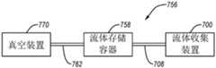
图7是根据一个实施例的包括流体收集组件700的系统756的示意图。流体收集组件700可以包括本文公开的任意流体收集组件。流体收集组件700可经由至少一个第一管708(例如,图1A的管108和图6的管608)与流体储存容器758流体连通。流体储存容器758定位在流体收集组件700的下游。流体储存容器758可以经由至少一个第二管762与真空源760流体连通。真空源760定位在流体储存容器758的下游。在操作期间,真空源760向流体收集组件700提供吸力。吸力将流体牵引进入腔室中并朝向第一管708牵引流体。进入第一管708的流体被吸力拉向流体储存容器758,使得流体储存容器758接收流体。流体储存容器758可以配置为抑制流体从流体储存容器758流至真空源760。FIG. 7 is a schematic diagram of a
虽然本文已经公开了各个方面和实施例,但是其他方面和实施例可以预期。本文公开的各个方面和实施例是出于说明的目的而非旨在进行限制。While various aspects and embodiments have been disclosed herein, other aspects and embodiments are contemplated. The various aspects and embodiments disclosed herein are for purposes of illustration and are not intended to be limiting.
程度的术语(例如,“大约”、“基本上”、“一般”等)表示结构或功能上的不显著变化。在一个示例中,当程度的术语包括指示量的术语时,程度的术语被解释为表示指示量的术语的±10%、±5%、+2%或0%。在一个示例中,当程度的术语用于修改形状时,程度的术语指示以程度的术语修改的形状具有所公开的形状的外观。例如,程度的术语可用于指示形状可以具有圆角而不是尖角、形状可以具有弯曲边缘而不是直边缘、形状可以具有从其延伸的一个或多个突起、形状可以是椭圆形的、形状与所公开的形状相同,等。Terms of degree (eg, "about", "substantially", "generally", etc.) mean insignificant changes in structure or function. In one example, when a term of degree includes a term indicating an amount, the term of degree is interpreted to mean ±10%, ±5%, +2%, or 0% of the term indicating an amount. In one example, when the term of degree is used to modify a shape, the term of degree indicates that the shape modified in the term of degree has the appearance of the disclosed shape. For example, the term degree may be used to indicate that a shape may have rounded corners rather than sharp corners, a shape may have curved edges rather than straight edges, a shape may have one or more protrusions extending therefrom, a shape may be oval, a shape similar to The disclosed shapes are the same, etc.
Claims (20)
Applications Claiming Priority (3)
| Application Number | Priority Date | Filing Date | Title |
|---|---|---|---|
| US201962889149P | 2019-08-20 | 2019-08-20 | |
| US62/889,149 | 2019-08-20 | ||
| PCT/US2020/046914WO2021034886A1 (en) | 2019-08-20 | 2020-08-19 | A fluid collection assembly including a reusable fluid impermeable barrier and at least one single use wicking cartridge |
Publications (2)
| Publication Number | Publication Date |
|---|---|
| CN114568016Atrue CN114568016A (en) | 2022-05-31 |
| CN114568016B CN114568016B (en) | 2024-12-17 |
Family
ID=72340413
Family Applications (1)
| Application Number | Title | Priority Date | Filing Date |
|---|---|---|---|
| CN202080073598.0AActiveCN114568016B (en) | 2019-08-20 | 2020-08-19 | Fluid collection assembly comprising a reusable fluid impermeable barrier and at least one disposable wicking cartridge |
Country Status (5)
| Country | Link |
|---|---|
| US (1) | US20220296408A1 (en) |
| EP (1) | EP4017434B1 (en) |
| CN (1) | CN114568016B (en) |
| ES (1) | ES2950275T3 (en) |
| WO (1) | WO2021034886A1 (en) |
Families Citing this family (41)
| Publication number | Priority date | Publication date | Assignee | Title |
|---|---|---|---|---|
| US10226376B2 (en) | 2014-03-19 | 2019-03-12 | Purewick Corporation | Apparatus and methods for receiving discharged urine |
| US10952889B2 (en) | 2016-06-02 | 2021-03-23 | Purewick Corporation | Using wicking material to collect liquid for transport |
| US10390989B2 (en) | 2014-03-19 | 2019-08-27 | Purewick Corporation | Apparatus and methods for receiving discharged urine |
| US11376152B2 (en) | 2014-03-19 | 2022-07-05 | Purewick Corporation | Apparatus and methods for receiving discharged urine |
| US11806266B2 (en) | 2014-03-19 | 2023-11-07 | Purewick Corporation | Apparatus and methods for receiving discharged urine |
| US10973678B2 (en) | 2016-07-27 | 2021-04-13 | Purewick Corporation | Apparatus and methods for receiving discharged urine |
| US10376406B2 (en) | 2016-07-27 | 2019-08-13 | Purewick Corporation | Male urine collection device using wicking material |
| JP2020510464A (en) | 2017-01-31 | 2020-04-09 | ピュアウィック コーポレイション | Apparatus and method for receiving excreted urine |
| WO2019212952A1 (en) | 2018-05-01 | 2019-11-07 | Purewick Corporation | Fluid collection devices, related systems, and related methods |
| KR102492111B1 (en) | 2018-05-01 | 2023-01-27 | 퓨어윅 코포레이션 | Fluid Collection Devices and Methods of Using The Same |
| KR102513810B1 (en) | 2018-05-01 | 2023-03-24 | 퓨어윅 코포레이션 | Fluid collection devices, systems and methods |
| WO2019212950A1 (en) | 2018-05-01 | 2019-11-07 | Purewick Corporation | Fluid collection devices, related systems, and related methods |
| JP7093851B2 (en) | 2018-05-01 | 2022-06-30 | ピュアウィック コーポレイション | Fluid collecting clothing |
| WO2020256865A1 (en) | 2019-06-21 | 2020-12-24 | Purewick Corporation | Fluid collection devices including a base securement area, and related systems and methods |
| US12329364B2 (en) | 2019-07-19 | 2025-06-17 | Purewick Corporation | Fluid collection devices including at least one shape memory material |
| US12350190B2 (en) | 2020-01-03 | 2025-07-08 | Purewick Corporation | Urine collection devices having a relatively wide portion and an elongated portion and related methods |
| ES2969642T3 (en) | 2020-04-10 | 2024-05-21 | Purewick Corp | Fluid collection assemblies that include one or more leak prevention features |
| US12048643B2 (en) | 2020-05-27 | 2024-07-30 | Purewick Corporation | Fluid collection assemblies including at least one inflation device and methods and systems of using the same |
| USD967409S1 (en) | 2020-07-15 | 2022-10-18 | Purewick Corporation | Urine collection apparatus cover |
| US20220047410A1 (en) | 2020-08-11 | 2022-02-17 | Purewick Corporation | Fluid collection assemblies defining waist and leg openings |
| US12156792B2 (en) | 2020-09-10 | 2024-12-03 | Purewick Corporation | Fluid collection assemblies including at least one inflation device |
| US11801186B2 (en) | 2020-09-10 | 2023-10-31 | Purewick Corporation | Urine storage container handle and lid accessories |
| GB2620326B (en)* | 2020-09-29 | 2024-06-26 | Martin Baker Aircraft Co Ltd | A urine collection system |
| US12042423B2 (en) | 2020-10-07 | 2024-07-23 | Purewick Corporation | Fluid collection systems including at least one tensioning element |
| US12257174B2 (en) | 2020-10-21 | 2025-03-25 | Purewick Corporation | Fluid collection assemblies including at least one of a protrusion or at least one expandable material |
| US12208031B2 (en) | 2020-10-21 | 2025-01-28 | Purewick Corporation | Adapters for fluid collection devices |
| US12048644B2 (en) | 2020-11-03 | 2024-07-30 | Purewick Corporation | Apparatus for receiving discharged urine |
| US12070432B2 (en) | 2020-11-11 | 2024-08-27 | Purewick Corporation | Urine collection system including a flow meter and related methods |
| US12245967B2 (en) | 2020-11-18 | 2025-03-11 | Purewick Corporation | Fluid collection assemblies including an adjustable spine |
| US12268627B2 (en) | 2021-01-06 | 2025-04-08 | Purewick Corporation | Fluid collection assemblies including at least one securement body |
| CA3162613A1 (en) | 2021-01-19 | 2022-07-19 | Purewick Corporation | Variable fit fluid collection devices, systems, and methods |
| US12178735B2 (en) | 2021-02-09 | 2024-12-31 | Purewick Corporation | Noise reduction for a urine suction system |
| EP4274524B1 (en) | 2021-02-26 | 2024-08-28 | Purewick Corporation | A male fluid collection device configured as a male urine collection device |
| US11938054B2 (en) | 2021-03-10 | 2024-03-26 | Purewick Corporation | Bodily waste and fluid collection with sacral pad |
| US12029677B2 (en) | 2021-04-06 | 2024-07-09 | Purewick Corporation | Fluid collection devices having a collection bag, and related systems and methods |
| US12233003B2 (en) | 2021-04-29 | 2025-02-25 | Purewick Corporation | Fluid collection assemblies including at least one length adjusting feature |
| US12251333B2 (en) | 2021-05-21 | 2025-03-18 | Purewick Corporation | Fluid collection assemblies including at least one inflation device and methods and systems of using the same |
| US12324767B2 (en) | 2021-05-24 | 2025-06-10 | Purewick Corporation | Fluid collection assembly including a customizable external support and related methods |
| US12150885B2 (en) | 2021-05-26 | 2024-11-26 | Purewick Corporation | Fluid collection system including a cleaning system and methods |
| WO2023018475A2 (en)* | 2021-06-11 | 2023-02-16 | Triton Systems, Inc. | Bladder collection system |
| WO2025048790A1 (en)* | 2023-08-29 | 2025-03-06 | Purewick Corporation | Fluid collection device having a conduit including a flow retainer |
Citations (7)
| Publication number | Priority date | Publication date | Assignee | Title |
|---|---|---|---|---|
| CN2455228Y (en)* | 2000-12-04 | 2001-10-24 | 李瑛� | Defecation aid |
| CN1367674A (en)* | 1998-10-02 | 2002-09-04 | 金伯利-克拉克环球有限公司 | Absorbent article having integral wicking barriers |
| CN201139671Y (en)* | 2007-12-21 | 2008-10-29 | 山东大学 | Minimally invasive negative pressure cystostomy indwelling device |
| WO2017210524A1 (en)* | 2016-06-02 | 2017-12-07 | Purewick Corporation | Apparatus and methods for receiving discharged urine |
| US20180028348A1 (en)* | 2016-07-27 | 2018-02-01 | Purewick Corporation | Male urine collection device using wicking material |
| US20190142624A1 (en)* | 2014-03-19 | 2019-05-16 | Purewick Corporation | Apparatus and methods for receiving discharged urine |
| CN110072494A (en)* | 2016-07-27 | 2019-07-30 | 普利维克公司 | Apparatus and method for receiving excreted urine |
Family Cites Families (7)
| Publication number | Priority date | Publication date | Assignee | Title |
|---|---|---|---|---|
| US4747166A (en)* | 1987-05-15 | 1988-05-31 | Kuntz David H | Fluid aspiration system for the management of urinary incontinence |
| US4886508A (en)* | 1988-07-11 | 1989-12-12 | Washington Douglas L | Ladies external catheter assembly |
| US6764477B1 (en)* | 1999-10-01 | 2004-07-20 | Kimberly-Clark Worldwide, Inc. | Center-fill absorbent article with reusable frame member |
| US20140257231A1 (en)* | 2013-03-08 | 2014-09-11 | The Procter & Gamble Company | Outer covers and disposable absorbent inserts for pants |
| US10390989B2 (en)* | 2014-03-19 | 2019-08-27 | Purewick Corporation | Apparatus and methods for receiving discharged urine |
| GB201417457D0 (en)* | 2014-10-02 | 2014-11-19 | Kalitasha Ltd | Hygiene device |
| US9308118B1 (en)* | 2014-10-27 | 2016-04-12 | Charles B. Dupree | Urine collection device |
- 2020
- 2020-08-19WOPCT/US2020/046914patent/WO2021034886A1/ennot_activeCeased
- 2020-08-19EPEP20765404.7Apatent/EP4017434B1/enactiveActive
- 2020-08-19ESES20765404Tpatent/ES2950275T3/enactiveActive
- 2020-08-19USUS17/635,866patent/US20220296408A1/enactivePending
- 2020-08-19CNCN202080073598.0Apatent/CN114568016B/enactiveActive
Patent Citations (7)
| Publication number | Priority date | Publication date | Assignee | Title |
|---|---|---|---|---|
| CN1367674A (en)* | 1998-10-02 | 2002-09-04 | 金伯利-克拉克环球有限公司 | Absorbent article having integral wicking barriers |
| CN2455228Y (en)* | 2000-12-04 | 2001-10-24 | 李瑛� | Defecation aid |
| CN201139671Y (en)* | 2007-12-21 | 2008-10-29 | 山东大学 | Minimally invasive negative pressure cystostomy indwelling device |
| US20190142624A1 (en)* | 2014-03-19 | 2019-05-16 | Purewick Corporation | Apparatus and methods for receiving discharged urine |
| WO2017210524A1 (en)* | 2016-06-02 | 2017-12-07 | Purewick Corporation | Apparatus and methods for receiving discharged urine |
| US20180028348A1 (en)* | 2016-07-27 | 2018-02-01 | Purewick Corporation | Male urine collection device using wicking material |
| CN110072494A (en)* | 2016-07-27 | 2019-07-30 | 普利维克公司 | Apparatus and method for receiving excreted urine |
Also Published As
| Publication number | Publication date |
|---|---|
| CN114568016B (en) | 2024-12-17 |
| EP4017434A1 (en) | 2022-06-29 |
| WO2021034886A1 (en) | 2021-02-25 |
| ES2950275T3 (en) | 2023-10-06 |
| EP4017434B1 (en) | 2023-06-14 |
| US20220296408A1 (en) | 2022-09-22 |
Similar Documents
| Publication | Publication Date | Title |
|---|---|---|
| CN114568016B (en) | Fluid collection assembly comprising a reusable fluid impermeable barrier and at least one disposable wicking cartridge | |
| EP4009877B1 (en) | Fluid collection assemblies incluidng a sample port | |
| CN112384178B (en) | Fluid collection device and method of use | |
| CN120187387A (en) | Urine collecting assembly including porous material and method of making a urine collecting assembly | |
| JP2024537729A (en) | Liquid collection assembly comprising a porous material having a first porous layer, a second porous layer, and a support layer - Patents.com | |
| CN114430676A (en) | Fluid collection assembly including one or more fluid flow features | |
| CN118302137A (en) | Fluid collection assembly including one or more leak-proof features | |
| JP2024512030A (en) | Fluid collection device with multi-part adhesive cover and related systems and methods | |
| JP2024528975A (en) | Molded or extruded fluid collection devices and related systems and methods - Patents.com | |
| CN116615162A (en) | Fluid collection device with reservoir between spout and barrier, and related systems and methods | |
| AU665008B2 (en) | Improved pad and pad tube connector for the management of urinary incontinence | |
| JP2024507424A (en) | Men's fluid collection assemblies and systems, methods of use thereof, and methods of manufacture thereof | |
| CA2138668C (en) | Vaginal discharge collection and drug delivery device | |
| JP2013501572A (en) | CATHETER HAVING HYDRAULIC FLUID STORAGE LOCATION AND / OR CATHETER PACKAGE USING THE CATHETER AND METHOD FOR PRODUCING AND / OR USING THE CATHETER | |
| EP0504301A1 (en) | Feminine hygiene device | |
| US20230190512A1 (en) | Female external catheter devices having a urethral cup, and related systems and methods | |
| JP2025504093A (en) | HAND-HELD URINARY COLLECTION PUMP DEVICE AND ASSOCIATED SYSTEMS AND METHODS | |
| US12016755B2 (en) | Tampon | |
| US20250170323A1 (en) | External female catheter system and method of use | |
| US20120116356A1 (en) | Cleansing Device |
Legal Events
| Date | Code | Title | Description |
|---|---|---|---|
| PB01 | Publication | ||
| PB01 | Publication | ||
| SE01 | Entry into force of request for substantive examination | ||
| SE01 | Entry into force of request for substantive examination | ||
| GR01 | Patent grant | ||
| GR01 | Patent grant |