CN114565550A - Identification code engraving quality detection method and terminal equipment - Google Patents
Identification code engraving quality detection method and terminal equipmentDownload PDFInfo
- Publication number
- CN114565550A CN114565550ACN202110287977.6ACN202110287977ACN114565550ACN 114565550 ACN114565550 ACN 114565550ACN 202110287977 ACN202110287977 ACN 202110287977ACN 114565550 ACN114565550 ACN 114565550A
- Authority
- CN
- China
- Prior art keywords
- identification code
- engraving
- vehicle identification
- code area
- vehicle
- Prior art date
- Legal status (The legal status is an assumption and is not a legal conclusion. Google has not performed a legal analysis and makes no representation as to the accuracy of the status listed.)
- Pending
Links
Images


Classifications
- G—PHYSICS
- G06—COMPUTING OR CALCULATING; COUNTING
- G06T—IMAGE DATA PROCESSING OR GENERATION, IN GENERAL
- G06T7/00—Image analysis
- G06T7/0002—Inspection of images, e.g. flaw detection
- G06T7/0004—Industrial image inspection
- G—PHYSICS
- G06—COMPUTING OR CALCULATING; COUNTING
- G06T—IMAGE DATA PROCESSING OR GENERATION, IN GENERAL
- G06T5/00—Image enhancement or restoration
- G06T5/70—Denoising; Smoothing
- G—PHYSICS
- G06—COMPUTING OR CALCULATING; COUNTING
- G06T—IMAGE DATA PROCESSING OR GENERATION, IN GENERAL
- G06T2207/00—Indexing scheme for image analysis or image enhancement
- G06T2207/20—Special algorithmic details
- G06T2207/20024—Filtering details
- G06T2207/20032—Median filtering
- G—PHYSICS
- G06—COMPUTING OR CALCULATING; COUNTING
- G06T—IMAGE DATA PROCESSING OR GENERATION, IN GENERAL
- G06T2207/00—Indexing scheme for image analysis or image enhancement
- G06T2207/30—Subject of image; Context of image processing
- G06T2207/30108—Industrial image inspection
- G06T2207/30164—Workpiece; Machine component
- Y—GENERAL TAGGING OF NEW TECHNOLOGICAL DEVELOPMENTS; GENERAL TAGGING OF CROSS-SECTIONAL TECHNOLOGIES SPANNING OVER SEVERAL SECTIONS OF THE IPC; TECHNICAL SUBJECTS COVERED BY FORMER USPC CROSS-REFERENCE ART COLLECTIONS [XRACs] AND DIGESTS
- Y02—TECHNOLOGIES OR APPLICATIONS FOR MITIGATION OR ADAPTATION AGAINST CLIMATE CHANGE
- Y02P—CLIMATE CHANGE MITIGATION TECHNOLOGIES IN THE PRODUCTION OR PROCESSING OF GOODS
- Y02P90/00—Enabling technologies with a potential contribution to greenhouse gas [GHG] emissions mitigation
- Y02P90/30—Computing systems specially adapted for manufacturing
Landscapes
- Engineering & Computer Science (AREA)
- Physics & Mathematics (AREA)
- General Physics & Mathematics (AREA)
- Theoretical Computer Science (AREA)
- Quality & Reliability (AREA)
- Computer Vision & Pattern Recognition (AREA)
- General Factory Administration (AREA)
Abstract
Translated fromChinese
Description
Translated fromChinese技术领域technical field
本发明涉及汽车制造技术领域,特别涉及一种识别码打刻质量检测方法及终端设备。The invention relates to the technical field of automobile manufacturing, in particular to a method and terminal equipment for detecting the quality of an identification code engraving.
背景技术Background technique
在汽车生产中,车辆识别码(Vehicle Identification Number,VIN)相当于汽车的身份证,其具有唯一性。车辆识别码一般通过打标机打刻在车身的主要承载部位上,其打刻质量直接影响车辆上牌等一系列后续流程,因而需要保证车辆识别码的打刻质量。In automobile production, the Vehicle Identification Number (VIN) is equivalent to the identity card of the automobile, which is unique. The vehicle identification code is generally engraved on the main bearing parts of the body by a marking machine, and its engraving quality directly affects a series of subsequent processes such as vehicle registration, so it is necessary to ensure the engraving quality of the vehicle identification code.
现有技术中,VIN打刻后一般采用人工拓印形式验证VIN打刻质量,不仅人工成本较高、效率低下,且人员检验容易发生误检,造成问题车辆流入市场,影响机动车上牌,对品牌形象和用户口碑都是极大的伤害。In the prior art, after the VIN is engraved, manual rubbing is generally used to verify the quality of the VIN engraving, which not only has high labor costs and low efficiency, but also is prone to false detections in personnel inspections, causing problem vehicles to flow into the market and affecting the registration of motor vehicles. Brand image and user word of mouth are both great harm.
发明内容SUMMARY OF THE INVENTION
有鉴于此,本发明旨在提出一种识别码打刻质量检测方法及终端设备,以解决现有车辆识别码打刻质量检验方式效率较低、且容易发生误检的问题。In view of this, the present invention aims to provide an identification code engraving quality detection method and a terminal device, so as to solve the problems that the existing vehicle identification code engraving quality inspection methods are inefficient and prone to false detection.
为达到上述目的,本发明的技术方案是这样实现的:In order to achieve the above object, the technical scheme of the present invention is achieved in this way:
一种识别码打刻质量检测方法,应用于终端设备,所述终端设备包括打标机,其中,所述打标机安装有视觉传感器,所述方法包括:A method for detecting quality of identification code engraving is applied to terminal equipment, wherein the terminal equipment includes a marking machine, wherein the marking machine is installed with a visual sensor, and the method includes:
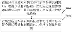
在所述打标机对车辆工件打刻完车辆识别码后,根据预设打刻标准,控制所述视觉传感器对所述车辆工件的车辆识别码区域进行视觉检验;After the marking machine finishes marking the vehicle identification code on the vehicle workpiece, control the visual sensor to perform visual inspection on the vehicle identification code area of the vehicle workpiece according to the preset marking standard;
在确定所述车辆识别码区域中的打刻信息不符合所述预设打刻标准时,进行打刻异常提醒。When it is determined that the marking information in the vehicle identification code area does not meet the preset marking standard, a marking abnormality reminder is performed.
进一步地,所述的识别码打刻质量检测方法中,所述在所述打标机对车辆工件打刻完车辆识别码后,根据预设打刻标准,控制所述视觉传感器对所述车辆工件的车辆识别码区域进行视觉检验的步骤,包括:Further, in the identification code engraving quality detection method, after the marking machine completes engraving the vehicle identification code on the vehicle workpiece, the visual sensor is controlled to detect the vehicle identification code according to a preset engraving standard. The steps for visual inspection of the VIN area of the workpiece include:
在所述打标机对车辆工件打刻完车辆识别码后,控制所述视觉传感器对所述车辆工件的车辆识别码区域进行拍摄,以获取车辆识别码区域图像;After the marking machine finishes marking the vehicle identification code on the vehicle workpiece, control the visual sensor to photograph the vehicle identification code area of the vehicle workpiece to obtain the vehicle identification code area image;
根据所述车辆识别码区域图像,确定实际的打刻信息,所述打刻信息至少包括字符个数、字符内容、每个字符的清晰度及打刻深度;According to the image of the vehicle identification code area, the actual engraving information is determined, and the engraving information at least includes the number of characters, the content of the characters, the definition and depth of each character;
根据所述打刻信息与所述预设打刻标准,对所述车辆工件的车辆识别码区域进行视觉检验。Visual inspection is performed on the vehicle identification code area of the vehicle workpiece according to the engraving information and the preset engraving standard.
进一步地,所述的识别码打刻质量检测方法中,所述根据所述打刻信息与所述预设打刻标准,对所述车辆工件的车辆识别码区域进行视觉检验的步骤,包括:Further, in the described identification code engraving quality detection method, the step of visually inspecting the vehicle identification code area of the vehicle workpiece according to the engraving information and the preset engraving standard includes:
在所述字符个数与打刻标准数量不同,和/或所述字符内容与目标车辆识别码不匹配,和/或任意一个字符的清晰度低于清晰度阈值,和/或任意一个字符的打刻深度低于深度阈值的情况下,确定所述打刻信息不符合预设打刻标准。When the number of characters is different from the standard number of engravings, and/or the content of the characters does not match the target vehicle identification code, and/or the definition of any one character is lower than the definition threshold, and/or the definition of any one character When the engraving depth is lower than the depth threshold, it is determined that the engraving information does not meet the preset engraving standard.
进一步地,所述的识别码打刻质量检测方法中,所述视觉传感器配置有多个角度不同的光源;Further, in the identification code engraving quality detection method, the vision sensor is configured with a plurality of light sources with different angles;
所述控制所述视觉传感器对所述车辆工件的车辆识别码区域进行拍摄,以获取车辆识别码区域图像的步骤,包括:The step of controlling the visual sensor to photograph the vehicle identification code area of the vehicle workpiece to obtain an image of the vehicle identification code area includes:
依次控制不同角度的光源对所述车辆识别码区域进行照射;Controlling light sources at different angles in turn to illuminate the vehicle identification code area;
针对每个对所述车辆识别码区域进行照射的所述光源,控制所述视觉传感器对所述车辆识别码区域进行拍摄,获得与所述光源对应角度的车辆识别码区域图像;For each of the light sources illuminating the vehicle identification code area, controlling the visual sensor to photograph the vehicle identification code area to obtain an image of the vehicle identification code area at an angle corresponding to the light source;
所述根据所述车辆识别码区域图像,确定实际的打刻信息的步骤,包括:The step of determining the actual engraving information according to the vehicle identification code area image includes:
根据各个补光灯对应角度的车辆识别码区域图像,确定实际的打刻信息。The actual engraving information is determined according to the image of the vehicle identification code area at the corresponding angle of each fill light.
进一步地,所述的识别码打刻质量检测方法中,所述终端设备建立有三维坐标与图像坐标的映射关系;Further, in the identification code engraving quality detection method, the terminal device establishes a mapping relationship between three-dimensional coordinates and image coordinates;
根据所述车辆识别码区域图像,确定实际的打刻信息的步骤,包括:According to the image of the vehicle identification code area, the steps of determining the actual engraving information include:
根据所述车辆识别码区域图像的图像坐标及所述映射关系,确定所述车辆识别码区域图像的三维坐标;determining the three-dimensional coordinates of the vehicle identification code area image according to the image coordinates of the vehicle identification code area image and the mapping relationship;
根据所述三维坐标,对所述车辆识别码区域图像进行矫正;correcting the image of the vehicle identification code area according to the three-dimensional coordinates;
根据矫正后的所述车辆识别码区域图像,确定实际的打刻信息。According to the corrected image of the vehicle identification code area, the actual engraving information is determined.
本发明的另一目的在于提出一种终端设备,其中,包括打标机及安装于所述打标机上的视觉传感器,所述终端设备还包括:Another object of the present invention is to provide a terminal device, which includes a marking machine and a visual sensor installed on the marking machine, and the terminal device further includes:
控制模块,用于在对车辆工件打刻完车辆识别码后,根据预设打刻标准,控制所述视觉传感器对所述车辆工件的识别码区域进行视觉检验;a control module, configured to control the visual sensor to perform visual inspection on the identification code area of the vehicle workpiece according to a preset marking standard after the vehicle identification code is engraved on the vehicle workpiece;
提醒模块,用于在确定所述识别码区域中的打刻信息不符合所述预设打刻标准时,进行打刻异常提醒。The reminding module is used to remind the abnormal engraving when it is determined that the engraving information in the identification code area does not meet the preset engraving standard.
进一步地,所述的终端设备中,所述控制模块包括:Further, in the terminal device, the control module includes:
控制单元,用于在所述打标机对车辆工件打刻完车辆识别码后,控制所述视觉传感器对所述车辆工件的车辆识别码区域进行拍摄,以获取车辆识别码区域图像;a control unit, configured to control the vision sensor to photograph the vehicle identification code area of the vehicle workpiece after the marking machine has finished marking the vehicle identification code on the vehicle workpiece, so as to obtain an image of the vehicle identification code area;
确定单元,用于根据所述车辆识别码区域图像,确定实际的打刻信息,所述打刻信息至少包括字符个数、字符内容、每个字符的清晰度及打刻深度;a determining unit, configured to determine the actual engraving information according to the image of the vehicle identification code area, the engraving information at least includes the number of characters, the content of the characters, the definition and the engraving depth of each character;
校验单元,用于根据所述打刻信息与所述预设打刻标准,对所述车辆工件的车辆识别码区域进行视觉检验。A verification unit, configured to perform visual inspection on the vehicle identification code area of the vehicle workpiece according to the engraving information and the preset engraving standard.
进一步地,所述的终端设备中,所述校验单元,具体用于在所述字符个数与打刻标准数量不同,和/或所述字符内容与目标车辆识别码不匹配,和/或任意一个字符的清晰度低于清晰度阈值,和/或任意一个字符的打刻深度低于深度阈值的情况下,确定所述打刻信息不符合预设打刻标准。Further, in the described terminal device, the verification unit is specifically configured to be used when the number of characters is different from the standard number of engravings, and/or the content of the characters does not match the target vehicle identification code, and/or When the definition of any character is lower than the definition threshold, and/or the engraving depth of any character is lower than the depth threshold, it is determined that the engraving information does not meet the preset engraving standard.
进一步地,所述的终端设备中,所述视觉传感器配置有多个角度不同的补光灯;所述控制单元包括:Further, in the terminal device, the visual sensor is configured with a plurality of fill lights with different angles; the control unit includes:
第一控制子单元,用于依次控制不同角度的补光灯对所述车辆识别码区域进行照射;a first control sub-unit, configured to sequentially control fill lights of different angles to illuminate the vehicle identification code area;
第二控制子单元,用于针对每个对所述车辆识别码区域进行照射的所述补光灯,控制所述视觉传感器对所述车辆识别码区域进行拍摄,获得与所述补光灯对应角度的车辆识别码区域图像;The second control subunit is configured to control the visual sensor to photograph the vehicle identification code area for each of the supplementary lights illuminating the vehicle identification code area, and obtain a corresponding light source corresponding to the supplementary light. Angled VIN area image;
所述确定单元,具体用于根据各个补光灯对应角度的车辆识别码区域图像,确定实际的打刻信息。The determining unit is specifically configured to determine the actual engraving information according to the image of the vehicle identification code area at the corresponding angle of each fill light.
进一步地,所述的终端设备中,所述终端设备建立有三维坐标与图像坐标的映射关系;所述确定单元包括:Further, in the terminal device, the terminal device establishes a mapping relationship between three-dimensional coordinates and image coordinates; the determining unit includes:
第一确定子单元,用于根据所述车辆识别码区域图像的图像坐标及所述映射关系,确定所述车辆识别码区域图像的三维坐标;a first determining subunit, configured to determine the three-dimensional coordinates of the vehicle identification code area image according to the image coordinates of the vehicle identification code area image and the mapping relationship;
矫正子单元,用于根据所述三维坐标,对所述车辆识别码区域图像进行矫正;a correction subunit, configured to correct the image of the vehicle identification code area according to the three-dimensional coordinates;
第二确定子单元,用于根据矫正后的所述车辆识别码区域图像,确定实际的打刻信息。The second determination subunit is used for determining the actual engraving information according to the corrected image of the vehicle identification code area.
进一步地,所述的终端设备中,所述视觉传感器通过连接装置集成于所述打标机的打刻针总成上。Further, in the terminal equipment, the visual sensor is integrated on the marking needle assembly of the marking machine through a connecting device.
进一步地,所述的终端设备中,所述打刻针总成包括打刻针安装板、固定于所述安装板上的打刻针固定装置及固定在所述打刻针固定装置处的打刻针;Further, in the terminal equipment, the engraving needle assembly includes an engraving needle mounting plate, an engraving needle fixing device fixed on the mounting plate, and a marking needle fixed device at the engraving needle fixing device. engraved needle;
所述连接装置套设于所述打刻针固定装置四周,并固定在所述安装板上;The connecting device is sleeved around the engraving needle fixing device and fixed on the mounting plate;
所述视觉传感器及所述补光灯固定在所述连接装置上,并绕所述打刻针分布。The visual sensor and the fill light are fixed on the connecting device and distributed around the engraving needle.
相对于在先技术,本发明所述的识别码打刻质量检测方法及终端设备具有以下优势:Compared with the prior art, the identification code engraving quality detection method and terminal device of the present invention have the following advantages:
预先在打标机上安装视觉传感器,并在打标机对车辆工件打刻完车辆识别码后,根据预设打刻标准,驱动视觉传感器对车辆工件的车辆识别码区域进行视觉检验;然后在确定车辆识别码区域中的打刻信息不符合预设打刻标准时,进行打刻异常提醒,不仅可以实现VIN打刻质量的智能自动质检,极大提升打刻质量检测效率,也减小了因误检导致不合格打刻质量的产品流入后续流程的概率,保证了产品质量。Install a vision sensor on the marking machine in advance, and after the marking machine has engraved the vehicle identification code on the vehicle workpiece, drive the vision sensor to visually inspect the vehicle identification code area of the vehicle workpiece according to the preset marking standard; When the engraving information in the vehicle identification code area does not meet the preset engraving standards, an abnormal engraving reminder will be given, which can not only realize the intelligent automatic quality inspection of the VIN engraving quality, greatly improve the engraving quality inspection efficiency, but also reduce the cause of the engraving. False detection leads to the probability of unqualified engraving quality products flowing into the subsequent process, ensuring product quality.
附图说明Description of drawings
构成本发明的一部分的附图用来提供对本发明的进一步理解,本发明的示意性实施例及其说明用于解释本发明,并不构成对本发明的不当限定。在附图中:The accompanying drawings constituting a part of the present invention are used to provide further understanding of the present invention, and the exemplary embodiments of the present invention and their descriptions are used to explain the present invention and do not constitute an improper limitation of the present invention. In the attached image:
图1为本发明一实施例所提出的识别码打刻质量检测方法的流程示意图;1 is a schematic flowchart of a method for detecting quality of identification code engraving proposed by an embodiment of the present invention;
图2为本发明实施例中的视觉校验软件框架示意图;2 is a schematic diagram of a visual verification software framework in an embodiment of the present invention;
图3为本发明实施例所提供的终端设备的控制过程示意图;3 is a schematic diagram of a control process of a terminal device provided by an embodiment of the present invention;
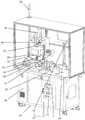
图4为本发明实施例所提出所提供的终端设备的结构示意图;FIG. 4 is a schematic structural diagram of a terminal device provided by an embodiment of the present invention;
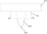
图5为本发明实施例中打刻针总成与视觉传感器的结构示意图;5 is a schematic structural diagram of a marking needle assembly and a vision sensor in an embodiment of the present invention;
图6为图5的A向剖视图。FIG. 6 is a cross-sectional view taken along the line A of FIG. 5 .
具体实施方式Detailed ways
下面将参考附图更详细地描述本申请的实施例。虽然附图中显示了本申请的实施例,然而应当理解,可以以各种形式实现本申请而不应被这里阐述的实施例所限制。相反,提供这些实施例是为了能够更彻底地理解本申请,并且能够将本申请的范围完整地传达给本领域的技术人员。Embodiments of the present application will be described in more detail below with reference to the accompanying drawings. Although embodiments of the present application are shown in the drawings, it should be understood that the present application may be embodied in various forms and should not be limited by the embodiments set forth herein. Rather, these embodiments are provided so that the present application will be more thoroughly understood, and will fully convey the scope of the present application to those skilled in the art.
需要说明的是,在不冲突的情况下,本发明中的实施例及实施例中的特征可以相互组合。It should be noted that the embodiments of the present invention and the features of the embodiments may be combined with each other under the condition of no conflict.
下面将参考附图并结合实施例来详细说明本发明。The present invention will be described in detail below with reference to the accompanying drawings and in conjunction with the embodiments.
请参阅图1,示出了本发明实施例所提供的一种识别码打刻质量检测方法的流程示意图,本发明实施例所提供的识别码打刻质量检测方法,应用于终端设备,所述终端设备包括打标机,所述打标机安装有视觉传感器,其中,所述方法包括步骤S100~S200。Please refer to FIG. 1, which shows a schematic flowchart of an identification code engraving quality detection method provided by an embodiment of the present invention. The identification code engraving quality detection method provided by the embodiment of the present invention is applied to a terminal device. The terminal device includes a marking machine, and the marking machine is installed with a vision sensor, wherein the method includes steps S100-S200.
在本发明实施例中,上述终端设备可以与制造执行系统(manufacturingexecution system,MSN),下载生产计划信息,并按照接收到的计划控制打标机对车辆工件进行打刻。In the embodiment of the present invention, the above-mentioned terminal device may work with a manufacturing execution system (manufacturing execution system, MSN) to download production plan information, and control the marking machine to mark the vehicle workpiece according to the received plan.
上述打标机可以未打标机分为划刻打标机、气动打标机、激光打标机等。其中,打标机的打刻深度大于0.3mm,打刻速度为10~100字/分钟,打刻范围为80×150mm,打刻硬度小于HRC60,打刻方向可在上下左右任意选择,打刻精度在0~0.04mm。The above-mentioned marking machines can be classified into non-marking machines into scribing marking machines, pneumatic marking machines, laser marking machines, and the like. Among them, the marking depth of the marking machine is greater than 0.3mm, the marking speed is 10-100 words/min, the marking range is 80×150mm, the marking hardness is less than HRC60, and the marking direction can be arbitrarily selected up, down, left and right. The accuracy is 0~0.04mm.
S100、在所述打标机对车辆工件打刻完车辆识别码后,根据预设打刻标准,控制所述视觉传感器对所述车辆工件的车辆识别码区域进行视觉检验。S100. After the marking machine has finished marking the vehicle identification code on the vehicle workpiece, control the visual sensor to perform visual inspection on the vehicle identification code area of the vehicle workpiece according to a preset marking standard.
上述步骤S100中,预设打刻标准为预先设置的车辆识别码打刻标准,也即需要达到的车辆识别码打刻效果,该预设打刻标准包括但不限于完整性标准、字符正确性标准、打刻字符残缺及重影标准、打开深度标准;车辆识别码区域为车辆工件上用于打刻车辆识别码的区域。In the above step S100, the preset engraving standard is the preset vehicle identification code engraving standard, that is, the vehicle identification code engraving effect that needs to be achieved. The preset engraving standard includes but is not limited to integrity standards, character correctness. Standard, incomplete engraved characters and ghosting standard, open depth standard; the vehicle identification code area is the area used to engrave the vehicle identification code on the vehicle workpiece.
上述步骤S100,即在打标机根据从MES系统提取的车辆识别码对工件放置区的车辆工件完成打刻后,控制视觉传感器对车辆工件上打刻有车辆识别码的区域进行视觉校验,以确定该车辆识别码区域的打刻效果是否达到目标要求。In the above step S100, after the marking machine completes marking the vehicle workpiece in the workpiece placement area according to the vehicle identification code extracted from the MES system, the visual sensor is controlled to perform visual verification on the area where the vehicle identification code is engraved on the vehicle workpiece, To determine whether the engraving effect of the vehicle identification code area meets the target requirements.
其中,打标机对车辆工件进行车辆识别码的打刻流程如下:操作人员将车辆工件放置到打标机的定位夹具上,放件完毕后按下夹紧按钮,将车辆工件一次装夹;双手按下开始按钮,上升气缸带动打标机自动下降到打刻位置并固定工件;打标机按照MES系统提取号码自动进行打刻;打刻完毕后,上升气缸带动打标机自动上升离开打刻位置。Among them, the marking process of marking the vehicle identification code on the vehicle workpiece by the marking machine is as follows: the operator places the vehicle workpiece on the positioning fixture of the marking machine, and presses the clamping button after placing the workpiece to clamp the vehicle workpiece at one time; Press the start button with both hands, and the ascending cylinder drives the marking machine to automatically descend to the marking position and fix the workpiece; the marking machine automatically marks according to the number extracted by the MES system; after marking, the ascending cylinder drives the marking machine to automatically rise and leave the marking engraved location.
步骤S200、在确定所述车辆识别码区域中的打刻信息不符合所述预设打刻标准时,进行打刻异常提醒。Step S200, when it is determined that the engraving information in the vehicle identification code area does not meet the preset engraving standard, an abnormal engraving reminder is performed.
在上述步骤S200中,利用视觉传感器获取车辆识别码区域中的打刻信息,并将该打开信息与上述预设打刻标准进行对比,在确定上述打刻信息不符合所述预设打刻标准时,说明打刻信息未能达到目标效果,需要人为干预进行处理,因而进行打刻异常提醒,以告知操作人员及时进行处理,同时自动进行系统记录;而在确定车辆识别码区域中的打刻信息符合预设打刻标准时,则控制打标机自动对打刻后的车辆工件进行取件操作,获取由操作人员进行手动取件。In the above-mentioned step S200, the engraving information in the vehicle identification code area is obtained by using a visual sensor, and the opening information is compared with the above-mentioned preset engraving standard. When it is determined that the above-mentioned engraving information does not meet the preset engraving standard , indicating that the engraving information fails to achieve the target effect and requires human intervention for processing, so an abnormal engraving reminder is issued to inform the operator to deal with it in time and automatically record the system; while the engraving information in the vehicle identification code area is determined. When the preset marking standard is met, the marking machine will be controlled to automatically pick up the engraved vehicle workpiece, and the operator will manually pick up the piece.
在实际应用中,在进行打刻异常提醒时,具体可以利用三色柱状灯进行声光报警,并在打标机的显示屏及安东屏上显示报警信息,告知操作人员进行故障处理,操作人员人工判断后进行修复或报废。In practical applications, when the marking abnormality is reminded, the three-color column lamp can be used to give sound and light alarm, and the alarm information can be displayed on the display screen of the marking machine and the Anton screen to inform the operator to troubleshoot and operate Repair or scrap it after manual judgment.
另外,在对车辆识别码区域图像进行视觉校验后,还需对各个车辆工件的车辆识别码打刻情况进行记录,以便于后续查询。In addition, after the visual verification of the image of the vehicle identification code area, it is necessary to record the engraving of the vehicle identification code of each vehicle workpiece to facilitate subsequent inquiries.
相对于现有技术,本发明所述的识别码打刻质量检测方法具有以下优势:Compared with the prior art, the identification code engraving quality detection method of the present invention has the following advantages:
预先在打标机上安装视觉传感器,并在打标机对车辆工件打刻完车辆识别码后,根据预设打刻标准,控制视觉传感器对车辆工件的车辆识别码区域进行视觉检验;然后在确定车辆识别码区域中的打刻信息不符合预设打刻标准时,进行打刻异常提醒,不仅可以实现VIN打刻质量的智能自动质检,极大提升打刻质量检测效率,也减小了因误检导致不合格打刻质量的产品流入后续流程的概率,保证了产品质量。Install a vision sensor on the marking machine in advance, and after the marking machine has engraved the vehicle identification code on the vehicle workpiece, control the vision sensor to visually inspect the vehicle identification code area of the vehicle workpiece according to the preset marking standard; When the engraving information in the vehicle identification code area does not meet the preset engraving standards, an abnormal engraving reminder will be given, which can not only realize the intelligent automatic quality inspection of the VIN engraving quality, greatly improve the engraving quality inspection efficiency, but also reduce the cause of the engraving. False detection leads to the probability of unqualified engraving quality products flowing into the subsequent process, ensuring product quality.
可选地,在一种实施方式中,上述步骤S100,具体包括步骤S101~S103:Optionally, in an implementation manner, the above step S100 specifically includes steps S101 to S103:
步骤S101、在所述打标机对车辆工件打刻完车辆识别码后,控制所述视觉传感器对所述车辆工件的车辆识别码区域进行拍摄,以获取车辆识别码区域图像。Step S101 , after the marking machine completes marking the vehicle identification code on the vehicle workpiece, control the vision sensor to photograph the vehicle identification code area of the vehicle workpiece to obtain an image of the vehicle identification code area.
在上述步骤S101中,在打标机根据从MES系统接收的VIN信息,对车辆共计进行打刻完成后,控制视觉传感器对车辆工件的车辆识别码区域进行拍摄,从而获取打刻完车辆识别码的车辆工件的车辆识别码区域图像。In the above step S101, after the marking machine completes the engraving of the vehicle according to the VIN information received from the MES system, the visual sensor is controlled to photograph the vehicle identification code area of the vehicle workpiece, so as to obtain the engraved vehicle identification code. The VIN area image of the vehicle workpiece.
步骤S102、根据所述车辆识别码区域图像,确定实际的打刻信息,所述打刻信息至少包括字符个数、字符内容、每个字符的清晰度及打刻深度。Step S102: Determine actual engraving information according to the image of the vehicle identification code area, where the engraving information at least includes the number of characters, the content of the characters, the definition and depth of each character.
在上述步骤S102中,上述实际的打刻信息为上述车辆识别码区域图像所包含的与车辆识别码打刻相关的信息,具体包括字符个数、字符内容、每个字符的清晰度及打刻深度等。In the above step S102, the actual engraving information is the information related to the engraving of the vehicle identification code contained in the image of the vehicle identification code area, which specifically includes the number of characters, the content of the characters, the definition and engraving of each character. depth etc.
在上述步骤S102中,即利用图像识别处理技术,对通过视觉传感器获取的车辆识别码区域图像进行识别处理,从而获得打标机在车辆工件的车辆识别码区域实际的打刻信息。In the above step S102, the image recognition processing technology is used to recognize and process the VIC area image obtained by the visual sensor, thereby obtaining the actual marking information of the marking machine in the VIC area of the vehicle workpiece.
步骤S103、根据所述打刻信息与所述预设打刻标准,对所述车辆工件的车辆识别码区域进行视觉检验。Step S103: Visually inspect the vehicle identification code area of the vehicle workpiece according to the engraving information and the preset engraving standard.
在上述步骤S103中,将步骤S102所识别确定的打刻信息与上述预设打刻标准进行比对,确定上述打标机对车辆工件进行的车辆识别码打刻操作是否达到了目标效果,也即确定车辆识别码的打刻质量是否合格,从而实现对车辆识别码区域进行视觉检验。In the above step S103, the marking information identified and determined in the step S102 is compared with the above-mentioned preset marking standard to determine whether the vehicle identification code marking operation performed by the marking machine on the vehicle workpiece has reached the target effect, and also That is, it is determined whether the engraving quality of the vehicle identification code is qualified, so as to realize the visual inspection of the vehicle identification code area.
在本实施方式中,通过控制视觉传感器对车辆工件的车辆识别码区域进行拍摄,然后根据拍摄获得的车辆识别码区域图像进行实际的打刻信息,再利用打刻信息与预设打刻标准进行比对,即可以快速、准确地实现对车辆识别码区域的自动化、智能化视觉检验。In this embodiment, the vehicle identification code area of the vehicle workpiece is photographed by controlling the visual sensor, and then the actual engraving information is carried out according to the image of the vehicle identification code area obtained by shooting, and then the engraving information and the preset engraving standard are used to carry out the engraving information. By comparison, the automatic and intelligent visual inspection of the vehicle identification code area can be quickly and accurately realized.
可选地,在一种实施方式中,本发明实施例步骤S103具体包括步骤S1031:Optionally, in an implementation manner, step S103 in this embodiment of the present invention specifically includes step S1031:
步骤S1031、在所述字符个数与打刻标准数量不同,和/或所述字符内容与目标车辆识别码不匹配,和/或任意一个字符的清晰度低于清晰度阈值,和/或任意一个字符的打刻深度低于深度阈值的情况下,确定所述打刻信息不符合预设打刻标准。Step S1031, when the number of characters is different from the standard number for engraving, and/or the content of the characters does not match the target vehicle identification code, and/or the definition of any character is lower than the definition threshold, and/or any When the engraving depth of a character is lower than the depth threshold, it is determined that the engraving information does not meet the preset engraving standard.
在上述步骤S1031中,打刻标准数量指的是需要打刻的目标车辆识别码对应的字符数量,该目标车辆识别码由从MES数据库中接收的打刻计划中VIN条码信息获取,或者从打刻记录中的VIN条码信息获取,为本次打标机需要打刻在车辆工件上的车辆识别码;上述字符内容即实际打刻在车辆工件上的实际车辆识别码;上述清晰度由实际打刻的车辆识别码中每个字符的清晰程度、完整程度、有无重影等情况确定,用以保证单一字符的打刻质量;上述打刻深度指的是实际打刻的车辆识别码中字符的深度。In the above step S1031, the standard number of engraving refers to the number of characters corresponding to the target vehicle identification code to be engraved, and the target vehicle identification code is obtained from the VIN barcode information in the engraving plan received from the MES database, or obtained from the marking plan. The VIN barcode information obtained in the engraving record is the vehicle identification code that the marking machine needs to engrave on the vehicle workpiece; the above character content is the actual vehicle identification code actually engraved on the vehicle workpiece; the above clarity is determined by the actual marking The clarity, completeness and ghosting of each character in the engraved VIN are determined to ensure the engraving quality of a single character; the above engraving depth refers to the characters in the actual engraved VIN. depth.
在上述步骤S1031中,即在车辆工件中实际打刻的车辆识别码满足字符个数与打刻标准数量不同、字符内容与目标车辆识别码不匹配、字符的清晰度低于清晰度阈值、任意一个字符的打刻深度低于深度阈值中的任意一个情况时,即可以确定实际的打刻信息不符合预设打刻标准。In the above step S1031, that is, the vehicle identification code actually engraved in the vehicle workpiece satisfies that the number of characters is different from the standard number for engraving, the content of the characters does not match the target vehicle identification code, the definition of the characters is lower than the definition threshold, any When the engraving depth of a character is lower than any one of the depth thresholds, it can be determined that the actual engraving information does not meet the preset engraving standard.
优选地,在本实施方式中,上述视觉传感器配置有多个角度不同的补光灯,上述步骤S101包括步骤S1011~1012,上述步骤S102包括步骤S1021:Preferably, in this embodiment, the above-mentioned visual sensor is configured with a plurality of fill lights with different angles, the above-mentioned step S101 includes steps S1011-1012, and the above-mentioned step S102 includes step S1021:
步骤S1011、依次控制不同角度的补光灯对所述车辆识别码区域进行照射。Step S1011 , sequentially controlling fill lights of different angles to illuminate the vehicle identification code area.
上述步骤S1011中、多个补光灯的角度不同,通过依次控制不同角度的补光灯点亮,即可以实现从不同角度对车辆识别码区域进行照射。In the above step S1011, the angles of the plurality of supplementary lights are different, and by sequentially controlling the lighting of the supplementary lights at different angles, the vehicle identification code area can be illuminated from different angles.
步骤S1012、针对每个对所述车辆识别码区域进行照射的所述补光灯,控制所述视觉传感器对所述车辆识别码区域进行拍摄,获得与所述补光灯对应角度的车辆识别码区域图像。Step S1012, for each of the supplementary lights that illuminate the vehicle identification code area, control the vision sensor to photograph the vehicle identification code area, and obtain a vehicle identification code corresponding to the angle of the supplementary light. area image.
上述步骤S1012中、在保持视觉传感器与车辆工件的相对位置不变的前提下,在多个补光灯中的任意一个补光灯照射车辆识别码区域时,均控制视觉传感器对车辆共计的车辆识别码区域进行拍摄,从而获得该补光灯对应角度的车辆识别码区域图像。In the above-mentioned step S1012, on the premise that the relative position of the visual sensor and the vehicle workpiece is kept unchanged, when any one of the plurality of supplementary lights illuminates the vehicle identification code area, the visual sensor is controlled to the total number of vehicles of the vehicle. The identification code area is photographed, so as to obtain the vehicle identification code area image corresponding to the angle of the fill light.
步骤S1021、根据各个补光灯对应角度的车辆识别码区域图像,确定实际的打刻信息。Step S1021: Determine the actual engraving information according to the image of the vehicle identification code area at the corresponding angle of each fill light.
上述步骤S1021中、利用图像识别处理技术,对由视觉传感器在不同角度进行补光灯照射拍摄得到的多张车辆识别码区域图像进行识别处理,从而获得打标机在车辆工件的车辆识别码区域实际的打刻信息;上述打刻信息至少包括字符个数、字符内容、每个字符的清晰度及打刻深度,其中,将各个补光灯对应角度的车辆识别码区域图像通过算法合成深度图,实现打刻深度的检测,进而将该打刻深度与设定标准深度图像进行比较,判定打刻深度是否合格。In the above-mentioned step S1021, the image recognition processing technology is used to identify and process a plurality of vehicle identification code area images obtained by the visual sensor performing fill light illumination and shooting at different angles, so as to obtain the vehicle identification code area of the marking machine on the vehicle workpiece. The actual engraving information; the above engraving information includes at least the number of characters, the content of the characters, the clarity of each character and the engraving depth, wherein the image of the vehicle identification code area at the corresponding angle of each fill light is synthesized through an algorithm. , to realize the detection of the engraving depth, and then compare the engraving depth with the set standard depth image to determine whether the engraving depth is qualified.
在该实施方式中,通过为视觉传感器配置多个角度不同的补光灯,在进行打刻信息确定时,依次控制不同角度的补光灯对车辆识别码区域进行照射,并逐一驱动视觉传感器对车辆识别码区域进行拍摄,获得与补光灯对应角度的车辆识别码区域图像,不仅可以确定实际打刻的字符个数、字符内容及字符的清晰度,还可以通过算法合成深度图,实现打刻深度的检测。In this embodiment, by configuring a plurality of supplementary lights with different angles for the visual sensor, when the engraving information is determined, the supplementary lights of different angles are sequentially controlled to illuminate the vehicle identification code area, and the visual sensor is driven one by one Taking pictures of the vehicle identification code area, and obtaining the image of the vehicle identification code area corresponding to the angle of the fill light, not only the number of characters actually engraved, the content of the characters and the clarity of the characters can be determined, but also the depth map can be synthesized through an algorithm to realize the printing process. Engraving depth detection.
可选地,在一种实施方式中,终端设备建立有三维坐标与图像坐标的映射关系,上述步骤S102包括步骤S1022~S1024。Optionally, in an implementation manner, the terminal device establishes a mapping relationship between three-dimensional coordinates and image coordinates, and the foregoing step S102 includes steps S1022 to S1024.
本实施方式中,图像坐标为拍摄的图像实际显示在视觉传感器中时的坐标,三位坐标则为图像对应的拍摄对象在三位坐标系中的坐标。In this embodiment, the image coordinates are the coordinates when the captured image is actually displayed in the vision sensor, and the three-dimensional coordinates are the coordinates of the photographed object corresponding to the image in the three-dimensional coordinate system.
因为拍摄采集的图像与原始图像存在几何畸变误差,这种误差不能通过硬件的优化彻底消除,但可以利用标定软件算法来减弱这种误差对测量精度的影响。具体地,设置视觉传感器与工件放置区的相对位置不变,上述相对位置对应了较佳拍摄距离和拍摄角度,而视觉传感器对车辆工件的车辆识别码区域进行视觉校验时,车辆工件均放置在上述工件放置区内,因而可以预先通过视觉传感器对视场内不同角度的棋盘格标定板等标准图像的拍摄,结合标准图像对应的拍摄图像,求出视觉传感器的内参数、外参数以及畸变参数,从而建立三维坐标与图像坐标的映射关系。Because there is a geometric distortion error between the captured image and the original image, this error cannot be completely eliminated by hardware optimization, but a calibration software algorithm can be used to reduce the impact of this error on the measurement accuracy. Specifically, the relative position between the vision sensor and the workpiece placement area is set to remain unchanged, and the above-mentioned relative positions correspond to the preferred shooting distance and shooting angle. When the vision sensor visually checks the vehicle identification code area of the vehicle workpiece, the vehicle workpiece is placed In the above-mentioned workpiece placement area, standard images such as checkerboard calibration plates at different angles in the field of view can be photographed in advance through the vision sensor, and the internal parameters, external parameters and distortion of the vision sensor can be obtained by combining the photographed images corresponding to the standard images. parameters, so as to establish the mapping relationship between the three-dimensional coordinates and the image coordinates.
S1022、根据所述车辆识别码区域图像的图像坐标及所述映射关系,确定所述车辆识别码区域图像的三维坐标。S1022. Determine the three-dimensional coordinates of the vehicle identification code area image according to the image coordinates of the vehicle identification code area image and the mapping relationship.
上述步骤S1022中,在获取了车辆识别码区域图像后,即可确定出该车辆识别码区域图像的图像坐标,而上述映射关系确定了图像坐标与三位坐标之间的对应关系,也即可以确定出上述车辆识别码区域图像对应的三维坐标。In the above step S1022, after the vehicle identification code area image is obtained, the image coordinates of the vehicle identification code area image can be determined, and the above mapping relationship determines the corresponding relationship between the image coordinates and the three-dimensional coordinates, that is, the image coordinates can be determined. The three-dimensional coordinates corresponding to the above-mentioned vehicle identification code area image are determined.
S1023、根据所述三维坐标,对所述车辆识别码区域图像进行矫正。S1023. Correct the image of the vehicle identification code area according to the three-dimensional coordinates.
上述步骤S1023中,因为上述三维坐标为车辆识别码区域图像对应的拍摄对象在三维坐标系中的实际坐标,也即车辆识别码区域在三维坐标系中的坐标,反应了车辆识别码区域真实的字符信息、尺寸位置、数量等信息,因而可以利用该三维坐标对视觉传感器拍摄得到的车辆识别码区域图像进行矫正,使之与车辆识别码区域的真实信息相匹配。In the above-mentioned step S1023, because the above-mentioned three-dimensional coordinates are the actual coordinates in the three-dimensional coordinate system of the shooting object corresponding to the image of the vehicle identification code area, that is, the coordinates of the vehicle identification code area in the three-dimensional coordinate system, it reflects the real value of the vehicle identification code area. Character information, size, position, quantity and other information, so the three-dimensional coordinates can be used to correct the image of the vehicle identification code area captured by the vision sensor, so that it matches the real information of the vehicle identification code area.
S1024、根据矫正后的所述车辆识别码区域图像,确定实际的打刻信息。S1024. Determine the actual engraving information according to the corrected image of the vehicle identification code area.
上述步骤S1024中,因矫正后的车辆识别码区域图像与车辆识别码区域的真实信息相匹配,因而对矫正后的上述车辆识别码区域图像进行识别处理,即可以获得车辆识别码区域实际的打刻信息,进而可以准确判断打刻质量是否符合预设打刻标准。In the above step S1024, since the corrected image of the vehicle identification code area matches the real information of the vehicle identification code area, the corrected image of the vehicle identification code area is subjected to identification processing, and the actual pattern of the vehicle identification code area can be obtained. The engraving information can be accurately judged whether the engraving quality meets the preset engraving standard.
在上述实施方式中,预先标定三维坐标与图像坐标的映射关系,再在拍摄获得车辆识别码区域图像后,利用上述映射关系算法确定三维坐标,然后利用上述三位坐标对拍摄获得车辆识别码区域图像进行矫正,进而可以通过矫正后的图像确定真实的打刻信息,从而减弱拍摄图像与真实图像之间的几何畸变误差对测量精度的影响。In the above embodiment, the mapping relationship between the three-dimensional coordinates and the image coordinates is pre-calibrated, and after the image of the vehicle identification code area is obtained by shooting, the three-dimensional coordinates are determined by the above mapping relationship algorithm, and then the three-dimensional coordinates are used to photograph the obtained vehicle identification code area. The image is corrected, and then the real engraving information can be determined through the corrected image, thereby reducing the influence of the geometric distortion error between the captured image and the real image on the measurement accuracy.
在实际应用中,因为机械振动会对检测结果产生较大的影响,尤其是在VIN打刻过程中设备会产振动谐波,会对图像采集的精度产生波动,因而将VIN打刻过程设定为非图像采集时段,待打刻完毕后,视觉传感器进入标定采集位,并使伺服系统动力电源处于待机状态,在电势稳定的情况下进行图像采集,采集完成后恢复伺服动力系统。In practical applications, because mechanical vibration will have a greater impact on the detection results, especially in the process of VIN marking, the equipment will generate vibration harmonics, which will fluctuate the accuracy of image acquisition, so the VIN marking process is set. It is a non-image acquisition period. After the engraving is completed, the vision sensor enters the calibration acquisition position, and the power supply of the servo system is in a standby state. Image acquisition is performed under the condition of stable potential. After the acquisition is completed, the servo power system is restored.
可选地,上述步骤S102中,在对识别码区域图像进行识别处理时,先对图像进行图像滤波处理;并利用亚像素级边缘定位技术,对经过图像滤波处理后的识别码区域图像进行识别,确定识别码区域实际的打刻信息。Optionally, in the above step S102, when the identification code area image is identified and processed, the image is first subjected to image filtering processing; and the sub-pixel level edge location technology is used to identify the identification code area image after the image filtering process. , to determine the actual engraving information in the identification code area.
其中,图像滤波处理可以抑制采集到图像中存在的噪声,降低光源与灰度值不稳定的问题,提高信噪比,并保证图像上像素点间最小方差最小;因为对于高精度测量系统来说,粗边界像素级精度往往难以满足要求,而亚像素级边缘定位技术在像素级别位置通过细分算法与拟合方法结合可以使边缘位置达到0.1甚至0.01的亚像素级精度,使得系统检测精度得到保证。Among them, the image filtering process can suppress the noise in the collected image, reduce the problem of unstable light source and gray value, improve the signal-to-noise ratio, and ensure that the minimum variance between pixels on the image is the smallest; because for high-precision measurement systems , the pixel-level accuracy of the coarse boundary is often difficult to meet the requirements, and the sub-pixel-level edge positioning technology can achieve a sub-pixel-level accuracy of 0.1 or even 0.01 for the edge position at the pixel-level position through the combination of the subdivision algorithm and the fitting method, so that the system detection accuracy can be obtained. ensure.
另外,对于因供电电源波动以及光源本身的发光不稳定产生的随机起伏噪声,光响应非均匀性引起的空间起伏噪声,相机由于暗电流分布不均、各光敏元大小、间隔不等引起的噪声,可以选用亮度大、亮度可调、均匀性及稳定性好的视觉传感器光源和对图像控制器(Charge-coupled Device,CCD)进行合理的参数设置,实现对噪声的有效控制。In addition, for the random fluctuation noise caused by the fluctuation of the power supply and the luminous instability of the light source itself, the spatial fluctuation noise caused by the non-uniformity of the light response, the camera due to the uneven distribution of dark current, the size of each photosensitive element, the noise caused by the different intervals , you can choose a visual sensor light source with high brightness, adjustable brightness, good uniformity and stability, and set reasonable parameters for the image controller (Charge-coupled Device, CCD) to achieve effective noise control.
本发明实施例中,通过视觉校验软件对车辆识别码区域图像进行视觉校验,其中,视觉校验软件框架如图2所示,包括数据层、模型层及应用层;In the embodiment of the present invention, the visual verification software is used to visually verify the image of the vehicle identification code area, wherein the visual verification software framework is shown in FIG. 2 , including a data layer, a model layer and an application layer;
其中,数据层中存储有VIN生产数据、图像数据及模型数据,VIN生产数据为生产计划中每辆车的唯一编码,图像数据为通过视觉传感器采集的标准VIN字符打刻图像数据,模型数据为图像识别模型算法对应的数据,该图像数据和模型数据构成数据层的基础部分;Among them, VIN production data, image data and model data are stored in the data layer. The VIN production data is the unique code of each vehicle in the production plan, the image data is the standard VIN character engraved image data collected by the vision sensor, and the model data is The data corresponding to the image recognition model algorithm, the image data and the model data constitute the basic part of the data layer;
其中,模型层为用于处理和分析VIN数据及成像数据的模型单元,根据采集图像调用对用模型算法进行运算;由于部分车型VIN打刻金属面为模具冲压的拉延面,金属表面具有冲压过程中随机产生的拉延痕,模型层是使用均值滤波算法排除背景渐进的浓淡变化,只抽取对比度发生急剧变化的部分,以及使用中值滤波算法在保持轮廓的前提下排除大致设定范围的像素干扰,最后使用微分运算结合灰度变换抽取设定灰度范围内的像素点形成灰度图,然后由用于处理和分析VIN数据及成像数据的模型单元,根据采集图像调用对用模型算法进行运算;Among them, the model layer is a model unit for processing and analyzing VIN data and imaging data, and the model algorithm is called according to the collected images to perform operations; because the metal surface engraved on the VIN of some models is the drawing surface of die stamping, the metal surface has a stamping surface. For the drawing marks randomly generated in the process, the model layer uses the mean filter algorithm to exclude the gradual change of the background, only extracts the parts with sharp changes in contrast, and uses the median filter algorithm to exclude the roughly set range under the premise of maintaining the contour. Pixel interference, and finally use differential operation combined with grayscale transformation to extract pixels within the set grayscale range to form a grayscale image, and then use the model unit for processing and analyzing VIN data and imaging data to call the matching model algorithm according to the collected image. operate;
应用层则用于根据模型层运算完成后输出的结果,结合预设打刻标准,经过VIN特征捕捉及VIN差异识别后,判定检测结果的合规情况。The application layer is used to determine the compliance of the test results after VIN feature capture and VIN difference identification based on the output results after the operation of the model layer is completed, combined with the preset marking standards.
在实际应用中,本发明实施例所提供的终端设备的控制过程如图3所示,先从MES系统接收要打刻的VIN信息,待打刻的车辆工件夹紧固定后,打刻针总成按照接收的信息在车辆工件上进行打刻,打刻完毕后视觉传感器自动拍照检验,检验合格后,通过三色柱状灯绿色进行指示,同时显示屏进行显示;检验出现问题后,由系统自动记录问题,柱状灯红色灯亮,发出声光,同时显示屏和安东屏发出报警信息,告知操作人员进行故障处理;操作人员人工判断后进行修复或报废等人工处理。In practical applications, the control process of the terminal device provided by the embodiment of the present invention is shown in FIG. 3 . First, the VIN information to be engraved is received from the MES system. After the vehicle workpiece to be engraved is clamped and fixed, the engraving needle is always After the engraving is completed, the visual sensor will automatically take pictures for inspection. After passing the inspection, it will be indicated by the three-color column light green, and the display will display it at the same time; if there is a problem in the inspection, the system will automatically To record the problem, the red light of the column light is on, and sound and light are emitted. At the same time, the display screen and the Anton screen send out an alarm message to inform the operator to deal with the fault; the operator manually judges and repairs or scraps it.
本发明的另一目标在于提出一种终端设备,其中,请参阅图4,图4示出了本发明实施例所提出的一种终端设备的结构示意图,所述终端设备包括打标机10及安装于所述打标机上的视觉传感器20,所述终端设备还包括:Another objective of the present invention is to provide a terminal device. Please refer to FIG. 4 . FIG. 4 shows a schematic structural diagram of a terminal device provided by an embodiment of the present invention. The terminal device includes a marking
控制模块11,用于在对车辆工件打刻完车辆识别码后,根据预设打刻标准,控制所述视觉传感器对所述车辆工件的识别码区域进行视觉检验;The control module 11 is used to control the visual sensor to perform visual inspection on the identification code area of the vehicle workpiece according to a preset marking standard after the vehicle identification code is engraved on the vehicle workpiece;
提醒模块12,用于在确定所述识别码区域中的打刻信息不符合所述预设打刻标准时,进行打刻异常提醒。The reminding
本发明实施例所述的终端设备,预先在打标机10上安装视觉传感器20,并在打标机对车辆工件打刻完车辆识别码后,根据预设打刻标准,驱动视觉传感器对车辆工件的车辆识别码区域进行视觉检验;然后在确定车辆识别码区域中的打刻信息不符合预设打刻标准时,进行打刻异常提醒,不仅可以实现VIN打刻质量的智能自动质检,极大提升打刻质量检测效率,也减小了因误检导致不合格打刻质量的产品流入后续流程的概率,保证了产品质量。In the terminal device according to the embodiment of the present invention, the
具体地,上述终端设备由总控装置30、电控装置40、视觉装置、打刻装置和外围设施五部分构成,总控装置30包含工控机31及显示器32,工控机31包括上述控制模块11及提醒模块12,且安装有打刻软件、图像处理软件;视觉装置包含视觉控制器、视觉传感器20、传感器支架、补光灯;电控装置包含电源、控制箱、打刻控制单元;打刻装置包含打刻针总成51、气缸夹紧工装52、气动元件;外围部分包含工业机柜61、不间断电源、操作台62及升降机构63、气路系统、低压电器、柜工作台64、上升气缸机构65、工件支撑定位装具66、打标机10、按钮盒67等部分组成。Specifically, the above-mentioned terminal equipment is composed of five parts: a
上述提醒模块具体可以通过三色柱状灯68及显示器32进行打刻异常提醒。The above-mentioned reminder module can specifically remind the marking abnormality through the three-
可选地,在一种实施方式中,上述视觉传感器20通过连接装置21集成于上述打标机10的打刻针总成51上,使得视觉传感器可以保持在打刻工件的上方,确保可以完整清晰的拍摄打刻内容。Optionally, in one embodiment, the above-mentioned
可选地,如图5及图6所示,上述终端设备中,打刻针总成51包括打刻针安装板511、固定于上述安装板511上的打刻针固定装置512及固定在上述打刻针固定装置512处的打刻针513;上述连接装置21套设于上述打刻针固定装置512四周,并通过螺栓等经由固定孔23固定在上述安装板511上;上述视觉传感器20及上述补光灯22固定在上述连接装置21上,并绕上述打刻针513分布,从而可以从多个角度对打刻后的车辆工件进行照射,进而获得与补光灯对应角度的车辆识别码区域图像。Optionally, as shown in FIG. 5 and FIG. 6 , in the above-mentioned terminal equipment, the
具体地,安装板511呈半径为55mm且厚度为40的圆环状,且内环半径为25mm,相应地,上述打刻针固定装置呈柱状,且与安装板511相接处半径为25mm。上述补光灯可以设置3个或4个,上述固定孔也可以设置3个或4个。Specifically, the mounting
可选地,所述的终端设备中,所述控制模块包括:Optionally, in the terminal device, the control module includes:
控制单元,用于在所述打标机对车辆工件打刻完车辆识别码后,控制所述视觉传感器对所述车辆工件的车辆识别码区域进行拍摄,以获取车辆识别码区域图像;a control unit, configured to control the vision sensor to photograph the vehicle identification code area of the vehicle workpiece after the marking machine has finished marking the vehicle identification code on the vehicle workpiece, so as to obtain an image of the vehicle identification code area;
确定单元,用于根据所述车辆识别码区域图像,确定实际的打刻信息,所述打刻信息至少包括字符个数、字符内容、每个字符的清晰度及打刻深度;a determining unit, configured to determine the actual engraving information according to the image of the vehicle identification code area, the engraving information at least includes the number of characters, the content of the characters, the definition and the engraving depth of each character;
校验单元,用于根据所述打刻信息与所述预设打刻标准,对所述车辆工件的车辆识别码区域进行视觉检验。A verification unit, configured to perform visual inspection on the vehicle identification code area of the vehicle workpiece according to the engraving information and the preset engraving standard.
可选地,所述的终端设备中,所述校验单元,具体用于在所述字符个数与打刻标准数量不同,和/或所述字符内容与目标车辆识别码不匹配,和/或任意一个字符的清晰度低于清晰度阈值,和/或任意一个字符的打刻深度低于深度阈值的情况下,确定所述打刻信息不符合预设打刻标准。Optionally, in the terminal device, the verification unit is specifically configured to be used when the number of characters is different from the standard number of engravings, and/or the content of the characters does not match the target vehicle identification code, and/ Or when the sharpness of any character is lower than the sharpness threshold, and/or the engraving depth of any character is lower than the depth threshold, it is determined that the engraving information does not meet the preset engraving standard.
可选地,所述的终端设备中,所述视觉传感器配置有多个角度不同的补光灯;所述控制单元包括:Optionally, in the terminal device, the visual sensor is configured with a plurality of fill lights with different angles; the control unit includes:
第一控制子单元,用于依次控制不同角度的补光灯对所述车辆识别码区域进行照射;a first control sub-unit, configured to sequentially control fill lights of different angles to illuminate the vehicle identification code area;
第二控制子单元,用于针对每个对所述车辆识别码区域进行照射的所述补光灯,控制所述视觉传感器对所述车辆识别码区域进行拍摄,获得与所述补光灯对应角度的车辆识别码区域图像;The second control subunit is configured to control the visual sensor to photograph the vehicle identification code area for each of the supplementary lights illuminating the vehicle identification code area, and obtain a corresponding light source corresponding to the supplementary light. Angled VIN area image;
所述确定单元,具体用于根据各个补光灯对应角度的车辆识别码区域图像,确定实际的打刻信息。The determining unit is specifically configured to determine the actual engraving information according to the image of the vehicle identification code area at the corresponding angle of each fill light.
可选地,所述的终端设备中,所述终端设备建立有三维坐标与图像坐标的映射关系;所述确定单元包括:Optionally, in the terminal device, the terminal device establishes a mapping relationship between three-dimensional coordinates and image coordinates; the determining unit includes:
第一确定子单元,用于根据所述车辆识别码区域图像的图像坐标及所述映射关系,确定所述车辆识别码区域图像的三维坐标;a first determining subunit, configured to determine the three-dimensional coordinates of the vehicle identification code area image according to the image coordinates of the vehicle identification code area image and the mapping relationship;
矫正子单元,用于根据所述三维坐标,对所述车辆识别码区域图像进行矫正;a correction subunit, configured to correct the image of the vehicle identification code area according to the three-dimensional coordinates;
第二确定子单元,用于根据矫正后的所述车辆识别码区域图像,确定实际的打刻信息。The second determination subunit is used for determining the actual engraving information according to the corrected image of the vehicle identification code area.
关于上述终端设备的技术细节和好处已在上述方法中进行了详细阐述,此处不再赘述。The technical details and benefits of the above-mentioned terminal device have been described in detail in the above-mentioned method, and will not be repeated here.
综上所述,本申请提供的识别码打刻质量检测方法及终端设备,在打标机上安装视觉传感器,并在打标机对车辆工件打刻完车辆识别码后,根据预设打刻标准,驱动视觉传感器对车辆工件的车辆识别码区域进行视觉检验;然后在确定车辆识别码区域中的打刻信息不符合预设打刻标准时,进行打刻异常提醒,不仅可以实现VIN打刻质量的智能自动质检,极大提升打刻质量检测效率,也减小了因误检导致不合格打刻质量的产品流入后续流程的概率,保证了产品质量。To sum up, in the identification code engraving quality detection method and terminal equipment provided by this application, a visual sensor is installed on the marking machine, and after the marking machine has engraved the vehicle identification code on the vehicle workpiece, the marking standard is preset according to the preset engraving standard. , drive the vision sensor to visually inspect the vehicle identification code area of the vehicle workpiece; then when it is determined that the engraving information in the vehicle identification code area does not meet the preset engraving standards, it will remind the abnormal engraving, which can not only achieve the quality of VIN engraving Intelligent automatic quality inspection greatly improves the efficiency of engraving quality inspection, and also reduces the probability of unqualified engraving quality products flowing into the subsequent process due to false detection, ensuring product quality.
所属领域的技术人员可以清楚地了解到,为描述的方便和简洁,上述描述的系统、装置和单元的具体工作过程,可以参考前述方法实施例中的对应过程,在此不再赘述。Those skilled in the art can clearly understand that, for the convenience and brevity of description, the specific working process of the above-described systems, devices and units may refer to the corresponding processes in the foregoing method embodiments, which will not be repeated here.
以上所述仅为本发明的较佳实施例而已,并不用以限制本发明,凡在本发明的精神和原则之内所作的任何修改、等同替换和改进等,均应包含在本发明的保护范围之内。The above descriptions are only preferred embodiments of the present invention and are not intended to limit the present invention. Any modifications, equivalent replacements and improvements made within the spirit and principles of the present invention shall be included in the protection of the present invention. within the range.
以上所述,仅为本发明的具体实施方式,但本发明的保护范围并不局限于此,任何熟悉本技术领域的技术人员在本发明揭露的技术范围内,可轻易想到变化或替换,都应涵盖在本发明的保护范围之内。因此,本发明的保护范围应以权利要求的保护范围为准。The above are only specific embodiments of the present invention, but the protection scope of the present invention is not limited thereto. Any person skilled in the art can easily think of changes or substitutions within the technical scope disclosed by the present invention. should be included within the protection scope of the present invention. Therefore, the protection scope of the present invention should be subject to the protection scope of the claims.
Claims (10)
Translated fromChinesePriority Applications (1)
| Application Number | Priority Date | Filing Date | Title |
|---|---|---|---|
| CN202110287977.6ACN114565550A (en) | 2021-03-17 | 2021-03-17 | Identification code engraving quality detection method and terminal equipment |
Applications Claiming Priority (1)
| Application Number | Priority Date | Filing Date | Title |
|---|---|---|---|
| CN202110287977.6ACN114565550A (en) | 2021-03-17 | 2021-03-17 | Identification code engraving quality detection method and terminal equipment |
Publications (1)
| Publication Number | Publication Date |
|---|---|
| CN114565550Atrue CN114565550A (en) | 2022-05-31 |
Family
ID=81712305
Family Applications (1)
| Application Number | Title | Priority Date | Filing Date |
|---|---|---|---|
| CN202110287977.6APendingCN114565550A (en) | 2021-03-17 | 2021-03-17 | Identification code engraving quality detection method and terminal equipment |
Country Status (1)
| Country | Link |
|---|---|
| CN (1) | CN114565550A (en) |
Cited By (6)
| Publication number | Priority date | Publication date | Assignee | Title |
|---|---|---|---|---|
| CN116052185A (en)* | 2023-01-09 | 2023-05-02 | 四川轻化工大学 | System and method for identifying and engraving depth detection of vehicle VIN (vehicle identification number) code matched with template |
| CN116484891A (en)* | 2023-04-17 | 2023-07-25 | 笃准机器人智能科技(苏州)有限公司 | Method for checking two-dimensional code and character code error code on surface of workpiece after electrophoresis |
| CN117876429A (en)* | 2024-03-12 | 2024-04-12 | 潍坊海之晨人工智能有限公司 | Real standard platform of sports type industry vision |
| CN119618124A (en)* | 2024-11-21 | 2025-03-14 | 东风汽车股份有限公司 | Clamp fault positioning method, device, equipment and readable storage medium |
| CN120374736A (en)* | 2025-06-26 | 2025-07-25 | 陕西熠泽重工科技有限公司 | Industrial pneumatic marking system based on image recognition |
| WO2025194697A1 (en)* | 2024-03-22 | 2025-09-25 | 宁德时代新能源科技股份有限公司 | Code engraving apparatus, code engraving method, and method for code engraving error prevention |
Citations (5)
| Publication number | Priority date | Publication date | Assignee | Title |
|---|---|---|---|---|
| JPH07182436A (en)* | 1993-11-12 | 1995-07-21 | Yamada Mach Tool Kk | Carved character check system |
| CN207223202U (en)* | 2017-09-14 | 2018-04-13 | 四川伟图智能科技有限公司 | Laser Jet mark vision-based detection all-in-one machine |
| CN108038482A (en)* | 2017-12-22 | 2018-05-15 | 大连运明自动化技术有限公司 | A kind of automobile engine cylinder-body sequence number Visual intelligent identifying system |
| CN108872265A (en)* | 2018-07-23 | 2018-11-23 | 珠海格力智能装备有限公司 | Detection method, device and system |
| CN111652879A (en)* | 2020-07-01 | 2020-09-11 | 济南中正金码科技有限公司 | A kind of marking character quality detection system and method |
- 2021
- 2021-03-17CNCN202110287977.6Apatent/CN114565550A/enactivePending
Patent Citations (5)
| Publication number | Priority date | Publication date | Assignee | Title |
|---|---|---|---|---|
| JPH07182436A (en)* | 1993-11-12 | 1995-07-21 | Yamada Mach Tool Kk | Carved character check system |
| CN207223202U (en)* | 2017-09-14 | 2018-04-13 | 四川伟图智能科技有限公司 | Laser Jet mark vision-based detection all-in-one machine |
| CN108038482A (en)* | 2017-12-22 | 2018-05-15 | 大连运明自动化技术有限公司 | A kind of automobile engine cylinder-body sequence number Visual intelligent identifying system |
| CN108872265A (en)* | 2018-07-23 | 2018-11-23 | 珠海格力智能装备有限公司 | Detection method, device and system |
| CN111652879A (en)* | 2020-07-01 | 2020-09-11 | 济南中正金码科技有限公司 | A kind of marking character quality detection system and method |
Cited By (9)
| Publication number | Priority date | Publication date | Assignee | Title |
|---|---|---|---|---|
| CN116052185A (en)* | 2023-01-09 | 2023-05-02 | 四川轻化工大学 | System and method for identifying and engraving depth detection of vehicle VIN (vehicle identification number) code matched with template |
| CN116052185B (en)* | 2023-01-09 | 2023-10-31 | 四川轻化工大学 | Template matching vehicle VIN code identification and engraving depth detection system and method |
| CN116484891A (en)* | 2023-04-17 | 2023-07-25 | 笃准机器人智能科技(苏州)有限公司 | Method for checking two-dimensional code and character code error code on surface of workpiece after electrophoresis |
| CN116484891B (en)* | 2023-04-17 | 2024-01-26 | 笃准机器人智能科技(苏州)有限公司 | Method for checking two-dimensional code and character code error code on surface of workpiece after electrophoresis |
| CN117876429A (en)* | 2024-03-12 | 2024-04-12 | 潍坊海之晨人工智能有限公司 | Real standard platform of sports type industry vision |
| CN117876429B (en)* | 2024-03-12 | 2024-06-07 | 潍坊海之晨人工智能有限公司 | Real standard system of sports type industry vision |
| WO2025194697A1 (en)* | 2024-03-22 | 2025-09-25 | 宁德时代新能源科技股份有限公司 | Code engraving apparatus, code engraving method, and method for code engraving error prevention |
| CN119618124A (en)* | 2024-11-21 | 2025-03-14 | 东风汽车股份有限公司 | Clamp fault positioning method, device, equipment and readable storage medium |
| CN120374736A (en)* | 2025-06-26 | 2025-07-25 | 陕西熠泽重工科技有限公司 | Industrial pneumatic marking system based on image recognition |
Similar Documents
| Publication | Publication Date | Title |
|---|---|---|
| CN114565550A (en) | Identification code engraving quality detection method and terminal equipment | |
| CN102529019B (en) | A method for mold detection, protection and parts detection and removal | |
| CN110678003A (en) | PCB solder mask detection and repair integrated machine and process method | |
| JPH02231510A (en) | Substrate inspection device | |
| CN109142383A (en) | One kind being based on morphologic character defect inspection method and device | |
| JP2019196964A (en) | Learning support system of sorter, learning data collection method and inspection system | |
| CN113724240A (en) | Refrigerator caster detection method, system and device based on visual identification | |
| JP2009115566A (en) | Panel defect location identification device | |
| KR20170122540A (en) | Automated Vision Inspection System | |
| CN114972825A (en) | Method for realizing automatic detection of MMI key icon matrix | |
| CN111626995B (en) | Intelligent insert detection method and device for workpiece | |
| CN110599450B (en) | LED light source position correction method and system | |
| CN115255884B (en) | Robot roller automatic assembly system and method based on OpenCV vision processing | |
| CN119579559A (en) | A method, processor and system for detecting stud welding quality | |
| KR101522312B1 (en) | Inspection device for pcb product and inspecting method using the same | |
| JPH07107514B2 (en) | Display method and display device in substrate inspection apparatus | |
| CN113793321A (en) | Casting surface defect dynamic detection method and device based on machine vision | |
| US20220238396A1 (en) | Laser repair method and laser repair device | |
| JP2013188773A (en) | Device and method for detecting positional deviation of workpiece and computer program | |
| CN114473463B (en) | Intelligent screw installation method and equipment for industrial distribution box | |
| CN202903693U (en) | Surface defect detection device for copper plating of gravure cylinder | |
| JP2006251561A (en) | Defective pixel repairing method | |
| CN109596626A (en) | Highlight magnetic ring workpiece visual detection method | |
| CN212321469U (en) | Circuit board detection device | |
| TWI490463B (en) | Detecting method and detecting system for distinguishing the difference of two workpieces |
Legal Events
| Date | Code | Title | Description |
|---|---|---|---|
| PB01 | Publication | ||
| PB01 | Publication | ||
| SE01 | Entry into force of request for substantive examination | ||
| SE01 | Entry into force of request for substantive examination |