CN114559850A - A super fast charging group control system and control method based on matrix bus tie control - Google Patents
A super fast charging group control system and control method based on matrix bus tie controlDownload PDFInfo
- Publication number
- CN114559850A CN114559850ACN202111326712.9ACN202111326712ACN114559850ACN 114559850 ACN114559850 ACN 114559850ACN 202111326712 ACN202111326712 ACN 202111326712ACN 114559850 ACN114559850 ACN 114559850A
- Authority
- CN
- China
- Prior art keywords
- charging
- module
- control
- power
- demand
- Prior art date
- Legal status (The legal status is an assumption and is not a legal conclusion. Google has not performed a legal analysis and makes no representation as to the accuracy of the status listed.)
- Granted
Links
Images


Classifications
- B—PERFORMING OPERATIONS; TRANSPORTING
- B60—VEHICLES IN GENERAL
- B60L—PROPULSION OF ELECTRICALLY-PROPELLED VEHICLES; SUPPLYING ELECTRIC POWER FOR AUXILIARY EQUIPMENT OF ELECTRICALLY-PROPELLED VEHICLES; ELECTRODYNAMIC BRAKE SYSTEMS FOR VEHICLES IN GENERAL; MAGNETIC SUSPENSION OR LEVITATION FOR VEHICLES; MONITORING OPERATING VARIABLES OF ELECTRICALLY-PROPELLED VEHICLES; ELECTRIC SAFETY DEVICES FOR ELECTRICALLY-PROPELLED VEHICLES
- B60L53/00—Methods of charging batteries, specially adapted for electric vehicles; Charging stations or on-board charging equipment therefor; Exchange of energy storage elements in electric vehicles
- B60L53/60—Monitoring or controlling charging stations
- B60L53/62—Monitoring or controlling charging stations in response to charging parameters, e.g. current, voltage or electrical charge
- Y—GENERAL TAGGING OF NEW TECHNOLOGICAL DEVELOPMENTS; GENERAL TAGGING OF CROSS-SECTIONAL TECHNOLOGIES SPANNING OVER SEVERAL SECTIONS OF THE IPC; TECHNICAL SUBJECTS COVERED BY FORMER USPC CROSS-REFERENCE ART COLLECTIONS [XRACs] AND DIGESTS
- Y02—TECHNOLOGIES OR APPLICATIONS FOR MITIGATION OR ADAPTATION AGAINST CLIMATE CHANGE
- Y02T—CLIMATE CHANGE MITIGATION TECHNOLOGIES RELATED TO TRANSPORTATION
- Y02T90/00—Enabling technologies or technologies with a potential or indirect contribution to GHG emissions mitigation
- Y02T90/10—Technologies relating to charging of electric vehicles
- Y02T90/12—Electric charging stations
Landscapes
- Engineering & Computer Science (AREA)
- Power Engineering (AREA)
- Transportation (AREA)
- Mechanical Engineering (AREA)
- Charge And Discharge Circuits For Batteries Or The Like (AREA)
- Electric Propulsion And Braking For Vehicles (AREA)
Abstract
Description
Translated fromChinese技术领域technical field
本发明涉及充电技术领域,尤其是涉及一种基于矩阵式母联控制的超级快充群控系统及控制方法。The invention relates to the technical field of charging, in particular to a super fast charging group control system and control method based on matrix bus tie control.
背景技术Background technique
目前,我国公共充电设施建设很大程度上还存在缺口,充电设备往往供不应求,而传统直流充电桩功率固化,无法给不同功率需求的电动汽车充电,因此兼容性差。其次,传统直流充电桩无法适应电池技术迅速发展的需求,从而导致投资的充电设备无法持续使用,因此适应性差。且电动汽车充电设施建设具有建设周期长、各个场站单桩功率合理配置难度高、现场安装调试时间长、投资较大、功率浪费等缺点。随着未来电池技术迅速的发展,电动汽车充电倍率的大幅提升,各大车企不断突破大电流充电瓶颈,从而导致投资的常规充电设备无法持续使用。At present, there is still a large gap in the construction of public charging facilities in my country. The supply of charging equipment is often in short supply. However, the power of traditional DC charging piles is solidified and cannot be charged for electric vehicles with different power requirements, so the compatibility is poor. Secondly, traditional DC charging piles cannot adapt to the needs of the rapid development of battery technology, so that the invested charging equipment cannot be used continuously, so the adaptability is poor. Moreover, the construction of electric vehicle charging facilities has the disadvantages of long construction period, high difficulty in rationally configuring the power of single piles in each station, long on-site installation and commissioning time, large investment, and power waste. With the rapid development of battery technology in the future and the substantial increase in the charging rate of electric vehicles, major car companies continue to break through the bottleneck of high-current charging, resulting in the unsustainable use of conventional charging equipment invested in.
发明内容SUMMARY OF THE INVENTION
本发明是为了克服现有技术的单桩系统具有功率合理配置难度高、现场安装调试时间长、投资较大、功率浪费的问题,解决传统的全矩阵式群控系统具有结构设计复杂、成本过高、控制逻辑复杂不易稳定等缺点。The invention is to overcome the problems of the prior art single-pile system with high difficulty in reasonable power configuration, long on-site installation and debugging time, large investment and power waste, and solve the traditional full-matrix group control system with complex structural design, excessive cost High, complex control logic is not easy to stabilize and other shortcomings.
为了实现上述目的,本发明采用以下技术方案:In order to achieve the above object, the present invention adopts the following technical solutions:
一种基于矩阵式母联控制的超级快充群控系统的控制方法,包括以下内容:系统检测同时充电的车辆的充电需求,开始的时候,第一辆车占用180KW充电功率,第二辆车充电需求也是180KW,但是只剩余60KW的可用功率,当第一辆车大功率充电SOC达到99%的时候,需求会降至60KW左右,那么系统会立刻将冗余的120KW退出至空闲状态,然后分配投切给第二辆车需求使用;A control method for a super fast charging group control system based on matrix bus tie control, comprising the following contents: the system detects the charging demand of vehicles that are charged at the same time, and at the beginning, the first vehicle occupies 180KW of charging power, and the second vehicle The charging demand is also 180KW, but there is only 60KW of available power left. When the first vehicle high-power charging SOC reaches 99%, the demand will drop to about 60KW, then the system will immediately exit the redundant 120KW to the idle state, and then Allocate switching to the second vehicle needs to use;
通过30KW的功率极差分配,统计当前需求,根据当前需求使用功率分配算法分配具体的充电模块供充电桩使用。Through the power range distribution of 30KW, the current demand is counted, and the specific charging module is allocated for the charging pile using the power allocation algorithm according to the current demand.
作为优选,所述功率分配算法为:每个充电模块功率为30KW,云平台连接充电桩与充电模块,充电桩连接有短期、触摸屏、车辆交互系、电能表、充电控制、状态监测、液冷装置和数据采集;Preferably, the power distribution algorithm is: the power of each charging module is 30KW, the cloud platform is connected to the charging pile and the charging module, and the charging pile is connected with short-term, touch screen, vehicle interaction system, energy meter, charging control, state monitoring, liquid cooling devices and data collection;
云平台通过车辆交互采集当前使用的充电桩数量,即同时充电的车辆数量,若仅有一台车辆充电,则计算其当前需求,当前需求为与每个充电模块功率的比值为n,分配n+1个充电模块供当前充电桩使用;若当前需求小于30KW,系统根据功率分配算法投切一个对应的30KW的充电模块给当前充电桩使用,若需求大于30KW小于60KW则投切两个对应的30KW的充电模块给当前充电桩使用;The cloud platform collects the number of charging piles currently in use through vehicle interaction, that is, the number of vehicles being charged at the same time. If only one vehicle is charged, its current demand is calculated. The ratio of the current demand to the power of each charging module is n, and n+ is allocated. One charging module is used by the current charging pile; if the current demand is less than 30KW, the system switches a corresponding 30KW charging module for the current charging pile according to the power distribution algorithm, and if the demand is greater than 30KW and less than 60KW, it switches two corresponding 30KW The charging module is used by the current charging pile;
若当前充电车辆数量大于1,当前充电车辆数量为i,每个车辆的需求为Ni,判断总需求
一种基于矩阵式母联控制的超级快充群控系统,包括硬件连接部分和控制硬件连接部分的软件控制部分,硬件连接部分包括若干充电机和充电桩,每一台充电机对应十二个充电桩;每个充电机包括N个充电模块、N个A型PDU模块和一个B型PDU模块,每个充电模块均连接在同一个交流母线上,每个充电模块分别与一个A型PDU模块连接,每个充电桩与所有充电模块连接。A super fast charging group control system based on matrix bus tie control includes a hardware connection part and a software control part that controls the hardware connection part, the hardware connection part includes several chargers and charging piles, each charger corresponds to twelve Charging pile; each charger includes N charging modules, N A-type PDU modules and a B-type PDU module, each charging module is connected to the same AC bus, and each charging module is respectively connected with an A-type PDU module Connect, each charging pile is connected with all charging modules.
本发明将充电模块集成在一起提高功率,利用功率分配控制技术对充电模块进行集中控制和管理,动态分配给12个充电桩为电动汽车充电,充电桩之间功率完全共享,提高每个充电桩的最大输出,每个充电桩都可以获得最理想的充电功率,能高效的提升充电站的利用率及收益率。The invention integrates the charging modules to improve the power, uses the power distribution control technology to centrally control and manage the charging modules, dynamically allocates 12 charging piles to charge the electric vehicle, and completely shares the power between the charging piles, thereby increasing the power of each charging pile. The maximum output of each charging pile can obtain the most ideal charging power, which can effectively improve the utilization rate and profitability of the charging station.
作为优选,所述B型PDU模块为6进6出的PDU模块。Preferably, the B-type PDU module is a 6-in 6-out PDU module.
作为优选,所述A型PDU模块为1进6出的PDU模块B型PDU模块。Preferably, the A-type PDU module is a 1-in 6-out PDU module B-type PDU module.
作为优选,所述B型PDU模块一侧连接1-6号充电桩,B型PDU模块另一侧连接7-12号充电桩;数量为N/2的A型PDU模块与1-6号充电桩连接,剩余的数量为N/2的A型PDU模块与7-12号充电桩连接。Preferably, one side of the B-type PDU module is connected to No. 1-6 charging piles, and the other side of the B-type PDU module is connected to No. 7-12 charging piles; the number of A-type PDU modules is N/2 and No. 1-6 charging piles are connected. Pile connection, the remaining A-type PDU modules of N/2 are connected to No. 7-12 charging piles.
作为优选,所述充电模块功率为30KW,系统扩展功率为30NKW。Preferably, the power of the charging module is 30KW, and the system expansion power is 30NKW.
作为优选,所述十二个充电桩包括1号充电桩和2-12号充电桩,1号充电桩为超级快充桩,充电接口为额定500KW、500A@1000V的GBT液冷充电接口;2-12号充电桩为普通快充桩,充电接口为额定187KW、250A@750V的GBT自冷充电接口。Preferably, the twelve charging piles include No. 1 charging pile and No. 2-12 charging piles, No. 1 charging pile is a super fast charging pile, and the charging interface is a GBT liquid-cooled charging interface rated at 500KW and 500A@1000V; 2 -The No. 12 charging pile is an ordinary fast charging pile, and the charging interface is a GBT self-cooling charging interface rated at 187KW, 250A@750V.
作为优选,所述软件控制部分包括TCU控制模块、CCU控制模块、PCU控制模块和PDU控制模块;Preferably, the software control part includes a TCU control module, a CCU control module, a PCU control module and a PDU control module;
TCU控制模块包括CPU处理器、非易失性存储器、ESAM模块、定位模块、语音模块、通信接口、显示接口、开关量输入接口、开关量输出接口、时钟和电源,TCU控制模块与系统充电控制器通信;TCU control module includes CPU processor, non-volatile memory, ESAM module, positioning module, voice module, communication interface, display interface, digital input interface, digital output interface, clock and power supply, TCU control module and system charging control device communication;
CCU控制模块的电气接口包括充电连接控制导引、BMS通讯、电压电流采样与控制、开入状态监测、开出控制;The electrical interface of the CCU control module includes charging connection control guidance, BMS communication, voltage and current sampling and control, switch-in status monitoring, and switch-out control;
PCU控制模块电气接口包括充电模块控制、状态监测、开出控制;The electrical interface of the PCU control module includes charging module control, state monitoring, and opening control;
PDU控制模块上集成有功率分配接触器。Power distribution contactors are integrated on the PDU control module.
TCU、CCU、PCU、PDU等核心控制模块组成,各控制模块分工明确,各司其职,有利于系统功率和充电桩数的平滑扩展,且单桩故障不影响其他充电桩的正常使用,无需断总电即可安全维护。It consists of core control modules such as TCU, CCU, PCU, and PDU. Each control module has a clear division of labor and performs its own duties, which is conducive to the smooth expansion of system power and the number of charging piles, and the failure of a single pile does not affect the normal use of other charging piles. It can be safely maintained when the main power is cut off.
因此,本发明具有如下有益效果:Therefore, the present invention has the following beneficial effects:
1.功率共享,节能高效:将充电站内功率模块集中部署,以30KW的功率极差分配,如一辆电动汽车充电,需求仅为20KW,系统根据功率分配控制算法通过A型PDU投切1个30KW的单元功率模块给充电桩充电使用,致使每个充电桩都可以获得最理想的充电功率,能高效的提升充电站的利用率及收益率;1. Power sharing, energy saving and high efficiency: The power modules in the charging station are centrally deployed and distributed with a power range of 30KW. For example, an electric vehicle is charged with a demand of only 20KW. The system switches one 30KW through A-type PDU according to the power distribution control algorithm. The unit power module is used to charge the charging pile, so that each charging pile can obtain the most ideal charging power, which can effectively improve the utilization rate and profitability of the charging station;
2.功率动态分配,柔性充电:根据充电车辆BMS所发出的充电需求,动态分配充电功率,从而提高设备的使用率;在整个充电过程中,控制系统根据车辆需求的上升及下降,动态的增加及降低充电功率;2. Dynamic power distribution, flexible charging: According to the charging demand issued by the charging vehicle BMS, the charging power is dynamically allocated, thereby improving the utilization rate of the equipment; during the entire charging process, the control system dynamically increases according to the rise and fall of vehicle demand and reduce the charging power;
3.平滑扩展、可持续性:仅设计1#充电桩为超级快充接口,超级快充接口既可给普通的快充接口车辆充电,也可以给超级快充接口车辆充电。在不久的将来,超级快充电动汽车普及后,只需增加充电模块数量及A型PDU模块数量即可完成功率扩展,提高系统现在以及未来的兼容性;3. Smooth expansion and sustainability: Only 1# charging pile is designed as a super fast charging interface. The super fast charging interface can charge both ordinary fast charging interface vehicles and super fast charging interface vehicles. In the near future, after the popularization of super fast charging electric vehicles, power expansion can be completed by simply increasing the number of charging modules and the number of A-type PDU modules, improving the compatibility of the system now and in the future;
4.降低成本、快速部署:系统的控制逻辑为矩阵式母联控制逻辑,而常规群控系统的控制逻辑为全矩阵式控制逻辑,且控制逻辑复杂,不易稳定;两种功率控制的共同优点为每个功率模块均可投切至每台充电桩使用,但是本系统的充电机整体结构设计会更小、内部结构设计更为简便及容易实现,控制逻辑简易稳定,成本甚低。4. Cost reduction and rapid deployment: the control logic of the system is a matrix bus tie control logic, while the control logic of a conventional group control system is a full matrix control logic, and the control logic is complex and difficult to stabilize; the common advantages of the two power controls Each power module can be switched to each charging pile, but the overall structure design of the charger of this system will be smaller, the internal structure design will be simpler and easier to implement, the control logic is simple and stable, and the cost is very low.
附图说明Description of drawings
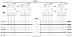
图1是实施例1的720KW超级快充群控系统功率分配控制框图。FIG. 1 is a block diagram of the power distribution control of the 720KW super fast charging group control system of the first embodiment.
图2是全矩阵式群控系统。Figure 2 is a full matrix group control system.
图3是实施例2的超级快充群控系统功率扩展图。FIG. 3 is a power expansion diagram of the super fast charging group control system of the second embodiment.
1.充电模块 2、A型PDU模块 3、B型PDU模块。1.
具体实施方式Detailed ways
下面结合附图与具体实施方式对本发明做进一步的描述。The present invention will be further described below with reference to the accompanying drawings and specific embodiments.
实施例1:Example 1:
本实施例提供了一种基于矩阵式母联控制的超级快充群控系统,包括硬件连接部分和控制硬件连接部分的软件控制部分,如图1所示,硬件连接部分包括若干充电机和充电桩,每一台充电机对应十二个充电桩;每个充电机包括24个充电模块1、24个A型PDU模块2和一个B型PDU模块3,每个充电模块均连接在同一个交流母线上,每个充电模块分别与一个A型PDU模块连接,每个充电桩与所有充电模块连接。This embodiment provides a super fast charging group control system based on matrix bus tie control, which includes a hardware connection part and a software control part that controls the hardware connection part. As shown in FIG. 1 , the hardware connection part includes several chargers and chargers. Each charger corresponds to twelve charging piles; each charger includes 24
A型PDU模块为1进6出的PDU模块B型PDU模块;B型PDU模块为6进6出的PDU模块;B型PDU模块一侧连接1-6号充电桩,B型PDU模块另一侧连接7-12号充电桩;数量为12的A型PDU模块与1-6号充电桩连接,剩余的数量为12的A型PDU模块与7-12号充电桩连接;实现矩阵式母联控制的功率分配,功率分配调节极差为30KW。每个充电桩均可以获取到所有的充电模块功率,每个充电模块均可以分配至12个充电桩上,即每个充电桩最大可输出720KW。Type A PDU module is a PDU module with 1 input and 6 outputs. Type B PDU module; Type B PDU module is a PDU module with 6 input and 6 outputs. Connect the 7-12 charging piles on the side; the A-type PDU modules with a quantity of 12 are connected with the 1-6 charging piles, and the remaining 12 A-type PDU modules are connected with the 7-12 charging piles; realize the matrix bus connection Controlled power distribution, the power distribution adjustment range is 30KW. Each charging pile can obtain all the power of the charging module, and each charging module can be allocated to 12 charging piles, that is, each charging pile can output a maximum of 720KW.
1号充电桩设计为超级快充桩,采用额定500KW、500A@1000V的GBT液冷充电接口,输出通过软件限流,长时间限流500A,短时间5分钟内允许达到600A。The No. 1 charging pile is designed as a super fast charging pile. It adopts a GBT liquid-cooled charging interface rated at 500KW and 500A@1000V. The output is limited by software. The current is limited to 500A for a long time, and it is allowed to reach 600A in a short time of 5 minutes.
2-12号充电桩设计为普通快充桩,采用额定187KW、250A@750V的GBT自冷充电接口,输出通过软件限流250A。No. 2-12 charging piles are designed as ordinary fast charging piles, using GBT self-cooling charging interface rated 187KW, 250A@750V, and the output is limited by software to 250A.
软件控制部分包括TCU控制模块、CCU控制模块、PCU控制模块和PDU控制模块;TCU是计费控制单元的简称,TCU控制模块包括CPU处理器、非易失性存储器、ESAM模块、定位模块、语音模块、通信接口、显示接口、开关量输入接口、开关量输出接口、时钟和电源,TCU控制模块与系统充电控制器通信;The software control part includes TCU control module, CCU control module, PCU control module and PDU control module; TCU is the abbreviation of charging control unit, TCU control module includes CPU processor, non-volatile memory, ESAM module, positioning module, voice module, communication interface, display interface, digital input interface, digital output interface, clock and power supply, the TCU control module communicates with the system charging controller;
CCU是充电控制器的简称,CCU控制模块的电气接口包括充电连接控制导引、BMS通讯、电压电流采样与控制、开入状态监测、开出控制;CCU is the abbreviation of charging controller. The electrical interface of CCU control module includes charging connection control guidance, BMS communication, voltage and current sampling and control, switch-in status monitoring, and switch-out control;
PCU是功率控制器的简称,PCU控制模块电气接口包括充电模块控制、状态监测、开出控制;PDU是功率分配模块的简称,功率分配接触器集成在PDU模块上,模块化设计,便于维护更换,主要负责电能的分配传送。PCU is the abbreviation of power controller. The electrical interface of PCU control module includes charging module control, status monitoring, and switch-out control; PDU is the abbreviation of power distribution module. The power distribution contactor is integrated on the PDU module, and the modular design is convenient for maintenance and replacement. , mainly responsible for the distribution and transmission of electric energy.
常规的充电站建设为120KW的单桩,如一辆纯电动汽车来充电,需求仅为20KW,那么将造成剩余100KW的资源浪费,长期以来,投资运营的收益率大大下降。A conventional charging station is constructed as a 120KW single pile. For example, a pure electric vehicle is charged with a demand of only 20KW, which will result in the waste of the remaining 100KW of resources. For a long time, the return on investment and operation will be greatly reduced.
而超级快充群控系统是将充电站内功率模块集中部署,以30KW的功率极差分配,如一辆电动汽车充电,需求仅为20KW,系统根据功率分配控制算法通过A型PDU投切1个30KW的单元功率模块给充电桩充电使用,致使每个充电桩都可以获得最理想的充电功率,能高效的提升充电站的利用率及收益率。The super fast charging group control system is to centrally deploy the power modules in the charging station and distribute them with a power difference of 30KW. For example, when an electric vehicle is charged, the demand is only 20KW. The system switches one 30KW through the A-type PDU according to the power distribution control algorithm. The unit power module is used to charge the charging pile, so that each charging pile can obtain the most ideal charging power, which can effectively improve the utilization rate and profitability of the charging station.
根据充电车辆BMS所发出的充电需求,动态分配充电功率,从而提高设备的使用率。在整个充电过程中,控制系统根据车辆需求的上升及下降,动态的增加及降低充电功率,例如:两辆车同时充电,开始的时候,第一辆车占用180KW充电功率,第二辆车充电需求也是180KW,但是只剩余60KW的可用功率,当第一辆车大功率充电SOC达到99%的时候,需求会降至60KW左右,那么系统会立刻将冗余的120KW退出至空闲状态,然后分配投切给第二辆车满需求使用。从而实现功率动态分配,柔性充电。According to the charging demand issued by the charging vehicle BMS, the charging power is dynamically allocated, thereby improving the utilization rate of the equipment. During the whole charging process, the control system dynamically increases and decreases the charging power according to the rise and fall of vehicle demand. For example, two vehicles are charged at the same time. At the beginning, the first vehicle occupies 180KW of charging power, and the second vehicle is charged. The demand is also 180KW, but only 60KW of available power is left. When the SOC of the first vehicle high-power charging reaches 99%, the demand will drop to about 60KW, then the system will immediately exit the redundant 120KW to the idle state, and then allocate Switch to the second car for full demand use. In this way, dynamic power distribution and flexible charging are realized.
如图2所示,传统的全矩阵式群控系统与本发明对比,两种系统的PDU模块所使用的接触器组数分别为150和288,每组接触器为正负极共2只,故本系统所使用的接触器数量可减少276只,目前市场上此型号接触器价格约80元左右,所以本系统单种器件的成本即可降低约2.2万元,且能实现同样的功率分配效果。As shown in Fig. 2, comparing the traditional full-matrix group control system with the present invention, the number of contactor groups used by the PDU modules of the two systems is 150 and 288 respectively, and each group of contactors is a total of 2 positive and negative electrodes. Therefore, the number of contactors used in this system can be reduced by 276. At present, the price of this type of contactor on the market is about 80 yuan, so the cost of a single device in this system can be reduced by about 22,000 yuan, and the same power distribution can be achieved. Effect.
本系统具有集中化、预装式的特点,可大量节省现场的安装调试时间,极大的缩短充电站的建设周期。The system has the characteristics of centralized and pre-installed type, which can save a lot of installation and debugging time on site and greatly shorten the construction period of charging stations.
实施例2:Example 2:
图3中充电模块数量为N,其余方案均与实施例1相同,对功率进行扩展,A型PDU模块数量也为N。N表示模块数量,若N=30,则整个系统扩展为900KW。In Fig. 3, the number of charging modules is N, and the rest of the solutions are the same as those in
PDU控制器可控制12只接触器的闭合及断开从而实现电能往各个充电桩的传输,且实时监测每个接触器的开合状态并上传给上级监控,确保功率分配投切的准确性、可靠性。The PDU controller can control the closing and opening of 12 contactors to realize the transmission of electric energy to each charging pile, and monitor the opening and closing status of each contactor in real time and upload it to the upper-level monitoring to ensure the accuracy of power distribution and switching. reliability.
充电机的功率仓独立设计,与其他部件结构隔离开来,形成独立的风道,配置调速风机用以散热,实时监测进风口及出风口的温升情况,设置安全阈值,一旦触发立即降额输出,从而实现本系统安全、稳定的运行。The power compartment of the charger is independently designed and separated from other components to form an independent air duct. It is equipped with a speed-adjusting fan for heat dissipation, real-time monitoring of the temperature rise of the air inlet and air outlet, and a safety threshold is set. Once triggered, it will drop immediately. output, so as to realize the safe and stable operation of the system.
超级快充桩配置液冷源及液冷充电枪,从而实现500KW的超级快充。超级快充桩内置温度传感器、压力传感器、流量传感器实时监测冷源的安全数据,从而提高大功率充电的安全性及可靠性。液冷源设计为预装式,可后期增装,为后期大功率超级快充车辆的普及,为兼容现在、拥抱未来,提供有利条件。The super fast charging pile is equipped with a liquid cooling source and a liquid cooling charging gun, so as to achieve a super fast charging of 500KW. The super fast charging pile has built-in temperature sensors, pressure sensors, and flow sensors to monitor the safety data of the cold source in real time, thereby improving the safety and reliability of high-power charging. The liquid cooling source is designed as a pre-installed type, which can be added later to provide favorable conditions for the popularization of high-power super fast-charging vehicles in the later period, and for being compatible with the present and embracing the future.
具有2种充电模式,智能充电模式和均分充电模式,总监控的用户设置界面上可设置。There are 2 charging modes, intelligent charging mode and equalized charging mode, which can be set on the user setting interface of total monitoring.
1、智能充电模式:1. Smart charging mode:
每台充电桩根据车辆的BMS需求,以先来先得的最优方式智能分配功率进行充电,适用于白天社会车辆及公交快速补电。According to the BMS requirements of the vehicle, each charging pile intelligently allocates power for charging on a first-come-first-served basis, which is suitable for fast charging of social vehicles and buses during the day.
2、均分充电模式:2. Equal charging mode:
每套720KW超级快充群控系统上的12台充电桩,无论BMS需求多少,12台充电桩均分输出,即每个充电桩固定60KW最大输出,适用于集中式直流充电站的车辆夜间集体补电,同时也避免了夜间光线不好,移车过程中导致车辆的擦碰等问题,而且整个夜间充电功率比较小,使得出现安全问题的几率更小。Each set of 12 charging piles on the 720KW super fast charging group control system, no matter how much the BMS needs, the 12 charging piles share the output equally, that is, each charging pile has a fixed maximum output of 60KW, which is suitable for vehicles in centralized DC charging stations at night. At the same time, it also avoids problems such as poor light at night and vehicle rubbing during the process of moving the car, and the charging power is relatively small throughout the night, making the probability of safety problems smaller.
本实施例还提供一种基于矩阵式母联控制的超级快充群控系统的控制方法,包括以下内容:系统检测同时充电的车辆的充电需求,开始的时候,第一辆车占用180KW充电功率,第二辆车充电需求也是180KW,但是只剩余60KW的可用功率,当第一辆车大功率充电SOC达到99%的时候,需求会降至60KW左右,那么系统会立刻将冗余的120KW退出至空闲状态,然后分配投切给第二辆车需求使用;This embodiment also provides a control method for a super fast charging group control system based on matrix bus tie control, including the following content: the system detects the charging demand of vehicles that are charged at the same time, and at the beginning, the first vehicle occupies 180KW of charging power , the charging demand of the second car is also 180KW, but only 60KW of available power is left. When the high-power charging SOC of the first car reaches 99%, the demand will drop to about 60KW, then the system will immediately withdraw the redundant 120KW. to the idle state, and then allocate switching to the second vehicle for use;
通过30KW的功率极差分配,统计当前需求,根据当前需求使用功率分配算法分配具体的充电模块供充电桩使用。Through the power range distribution of 30KW, the current demand is counted, and the specific charging module is allocated for the charging pile using the power allocation algorithm according to the current demand.
功率分配算法为:每个充电模块功率为30KW,云平台连接充电桩与充电模块,充电桩连接有短期、触摸屏、车辆交互系、电能表、充电控制、状态监测、液冷装置和数据采集;云平台通过车辆交互采集当前使用的充电桩数量,即同时充电的车辆数量,若仅有一台车辆充电,则计算其当前需求,当前需求为与每个充电模块功率的比值为n,分配n+1个充电模块供当前充电桩使用;若当前需求小于30KW,系统根据功率分配算法投切一个对应的30KW的充电模块给当前充电桩使用,若需求大于30KW小于60KW则投切两个对应的30KW的充电模块给当前充电桩使用;The power distribution algorithm is: the power of each charging module is 30KW, the cloud platform connects the charging pile and the charging module, and the charging pile is connected with short-term, touch screen, vehicle interaction system, electric energy meter, charging control, state monitoring, liquid cooling device and data acquisition; The cloud platform collects the number of charging piles currently in use through vehicle interaction, that is, the number of vehicles being charged at the same time. If only one vehicle is charged, its current demand is calculated. The ratio of the current demand to the power of each charging module is n, and n+ is allocated. One charging module is used by the current charging pile; if the current demand is less than 30KW, the system switches a corresponding 30KW charging module for the current charging pile according to the power distribution algorithm, and if the demand is greater than 30KW and less than 60KW, it switches two corresponding 30KW The charging module is used by the current charging pile;
若当前充电车辆数量大于1,当前充电车辆数量为i,每个车辆的需求为Ni,判断总需求
上述实施例对本发明的具体描述,只用于对本发明进行进一步说明,不能理解为对本发明保护范围的限定,本领域的技术工程师根据上述发明的内容对本发明作出一些非本质的改进和调整均落入本发明的保护范围内。The specific description of the present invention in the above embodiments is only used to further illustrate the present invention, and should not be construed as a limitation on the protection scope of the present invention. Some non-essential improvements and adjustments made to the present invention by technical engineers in the field according to the content of the above invention are all within the scope of the present invention. into the protection scope of the present invention.
Claims (9)
Translated fromChinese
Priority Applications (1)
| Application Number | Priority Date | Filing Date | Title |
|---|---|---|---|
| CN202111326712.9ACN114559850B (en) | 2021-11-10 | 2021-11-10 | Super quick charge group control system based on matrix type bus-tie control and control method |
Applications Claiming Priority (1)
| Application Number | Priority Date | Filing Date | Title |
|---|---|---|---|
| CN202111326712.9ACN114559850B (en) | 2021-11-10 | 2021-11-10 | Super quick charge group control system based on matrix type bus-tie control and control method |
Publications (2)
| Publication Number | Publication Date |
|---|---|
| CN114559850Atrue CN114559850A (en) | 2022-05-31 |
| CN114559850B CN114559850B (en) | 2024-06-25 |
Family
ID=81712148
Family Applications (1)
| Application Number | Title | Priority Date | Filing Date |
|---|---|---|---|
| CN202111326712.9AActiveCN114559850B (en) | 2021-11-10 | 2021-11-10 | Super quick charge group control system based on matrix type bus-tie control and control method |
Country Status (1)
| Country | Link |
|---|---|
| CN (1) | CN114559850B (en) |
Cited By (2)
| Publication number | Priority date | Publication date | Assignee | Title |
|---|---|---|---|---|
| CN115972965A (en)* | 2023-02-20 | 2023-04-18 | 广东天枢新能源科技有限公司 | Charging control method, system and device applied to charging stack and storage medium |
| WO2025015929A1 (en)* | 2023-07-14 | 2025-01-23 | 福建时代星云科技有限公司 | Charging stack power distribution system and method based on matrix control |
Citations (12)
| Publication number | Priority date | Publication date | Assignee | Title |
|---|---|---|---|---|
| US20150165917A1 (en)* | 2011-12-29 | 2015-06-18 | Abb B.V. | Method, system and charger for charging a battery of an electric vehicle |
| CN106945539A (en)* | 2017-04-18 | 2017-07-14 | 中天昱品科技有限公司 | A kind of electric automobile automated power distribution direct current quick charger and its control method |
| US20180178662A1 (en)* | 2016-12-27 | 2018-06-28 | Phihong Technology Co., Ltd. | Intelligent power distributing system for charging station |
| CN108631408A (en)* | 2018-06-04 | 2018-10-09 | 深圳巴斯巴科技发展有限公司 | New-energy automobile charging pile intelligent dispensing system |
| CN109398133A (en)* | 2018-10-29 | 2019-03-01 | 河南英开电气股份有限公司 | A kind of electric car charging cluster and its power automatic distributing system |
| CN109455106A (en)* | 2018-10-17 | 2019-03-12 | 国网浙江省电力有限公司杭州供电公司 | A kind of electric car Intelligent charging station |
| DE102017124469A1 (en)* | 2017-09-28 | 2019-03-28 | Engeln & Masnitza & Wagner GbR (vertretungsberechtigte Gesellschafter Michael Masnitza, 90473 Nürnberg, Tobias Wagner, 81735 München, Johannes Engeln A, 85053 Ingolstadt) | Modular device for the time-delayed charging of several electric vehicles at a charging station |
| CN109572454A (en)* | 2018-10-17 | 2019-04-05 | 国网浙江省电力有限公司杭州供电公司 | A kind of electric car Intelligent charging station charging system |
| CN110797928A (en)* | 2018-08-02 | 2020-02-14 | 郑州宇通客车股份有限公司 | Charging station load balance management method and device |
| CN111016724A (en)* | 2019-12-18 | 2020-04-17 | 广东电科院能源技术有限责任公司 | Charging pile self-adaptive power distribution method, system and equipment |
| CN112937350A (en)* | 2021-02-05 | 2021-06-11 | 开迈斯新能源科技有限公司 | Charging pile management method and device |
| US20210178925A1 (en)* | 2019-12-16 | 2021-06-17 | Dr. Ing. H.C. F. Porsche Aktiengesellschaft | Method and charging station for load management with fall-back solution |
- 2021
- 2021-11-10CNCN202111326712.9Apatent/CN114559850B/enactiveActive
Patent Citations (12)
| Publication number | Priority date | Publication date | Assignee | Title |
|---|---|---|---|---|
| US20150165917A1 (en)* | 2011-12-29 | 2015-06-18 | Abb B.V. | Method, system and charger for charging a battery of an electric vehicle |
| US20180178662A1 (en)* | 2016-12-27 | 2018-06-28 | Phihong Technology Co., Ltd. | Intelligent power distributing system for charging station |
| CN106945539A (en)* | 2017-04-18 | 2017-07-14 | 中天昱品科技有限公司 | A kind of electric automobile automated power distribution direct current quick charger and its control method |
| DE102017124469A1 (en)* | 2017-09-28 | 2019-03-28 | Engeln & Masnitza & Wagner GbR (vertretungsberechtigte Gesellschafter Michael Masnitza, 90473 Nürnberg, Tobias Wagner, 81735 München, Johannes Engeln A, 85053 Ingolstadt) | Modular device for the time-delayed charging of several electric vehicles at a charging station |
| CN108631408A (en)* | 2018-06-04 | 2018-10-09 | 深圳巴斯巴科技发展有限公司 | New-energy automobile charging pile intelligent dispensing system |
| CN110797928A (en)* | 2018-08-02 | 2020-02-14 | 郑州宇通客车股份有限公司 | Charging station load balance management method and device |
| CN109455106A (en)* | 2018-10-17 | 2019-03-12 | 国网浙江省电力有限公司杭州供电公司 | A kind of electric car Intelligent charging station |
| CN109572454A (en)* | 2018-10-17 | 2019-04-05 | 国网浙江省电力有限公司杭州供电公司 | A kind of electric car Intelligent charging station charging system |
| CN109398133A (en)* | 2018-10-29 | 2019-03-01 | 河南英开电气股份有限公司 | A kind of electric car charging cluster and its power automatic distributing system |
| US20210178925A1 (en)* | 2019-12-16 | 2021-06-17 | Dr. Ing. H.C. F. Porsche Aktiengesellschaft | Method and charging station for load management with fall-back solution |
| CN111016724A (en)* | 2019-12-18 | 2020-04-17 | 广东电科院能源技术有限责任公司 | Charging pile self-adaptive power distribution method, system and equipment |
| CN112937350A (en)* | 2021-02-05 | 2021-06-11 | 开迈斯新能源科技有限公司 | Charging pile management method and device |
Cited By (2)
| Publication number | Priority date | Publication date | Assignee | Title |
|---|---|---|---|---|
| CN115972965A (en)* | 2023-02-20 | 2023-04-18 | 广东天枢新能源科技有限公司 | Charging control method, system and device applied to charging stack and storage medium |
| WO2025015929A1 (en)* | 2023-07-14 | 2025-01-23 | 福建时代星云科技有限公司 | Charging stack power distribution system and method based on matrix control |
Also Published As
| Publication number | Publication date |
|---|---|
| CN114559850B (en) | 2024-06-25 |
Similar Documents
| Publication | Publication Date | Title |
|---|---|---|
| CN115056676B (en) | Charging systems for battery swap stations or energy storage stations | |
| CN208069424U (en) | Flexible charging station | |
| CN108674247B (en) | Energy storage type free linkage direct current charging system | |
| CN204559201U (en) | A kind of split type direct-current charging post of electric automobile and system | |
| CN114050621B (en) | Distributed energy storage power distribution system and method | |
| CN106058844A (en) | Multi-port energy router for DC micro network | |
| CN109120051A (en) | A kind of intelligent multichannel mixed battery manager, the control method of lithium battery power supply unit, base station | |
| CN112087023B (en) | Energy storage system, control method and intermittent power supply energy storage device | |
| CN110739741B (en) | Low-voltage direct-current coupling management system of high-voltage power battery in communication base station | |
| CN106218440B (en) | A kind of power intelligent of charging equipment adjusts circuit and method | |
| CN105337306A (en) | Optical storage integrated power generation system | |
| CN114559850B (en) | Super quick charge group control system based on matrix type bus-tie control and control method | |
| CN107444188A (en) | A kind of annular power shares intelligent charging machine and its charging method | |
| CN110854981A (en) | Circuit system and control method of dual power distribution cabinet for electric tractor | |
| CN111546942A (en) | Low-voltage direct-current charging and discharging source management system of high-voltage power battery in communication base station | |
| CN110040009B (en) | Electric vehicle solar-assisted charging system and method thereof, and electric vehicle | |
| CN114172242A (en) | Bidirectional charging and discharging system and control method thereof | |
| CN112186822A (en) | Energy storage system based on low-voltage isolation battery unit | |
| CN110165689A (en) | A kind of control system for energy-storage system and corresponding energy-storage system | |
| CN115085256A (en) | Mobile energy management and control system and method | |
| CN102097975A (en) | Complementary solar power generation system | |
| CN210430931U (en) | Energy storage air conditioning system | |
| CN114932828B (en) | Intelligent group control charging method and system for electric automobile | |
| CN211617481U (en) | Low-voltage direct-current charging and discharging source management equipment of high-voltage power battery in communication base station | |
| CN207607368U (en) | A kind of shared intelligent charging machine of annular power |
Legal Events
| Date | Code | Title | Description |
|---|---|---|---|
| PB01 | Publication | ||
| PB01 | Publication | ||
| SE01 | Entry into force of request for substantive examination | ||
| SE01 | Entry into force of request for substantive examination | ||
| GR01 | Patent grant | ||
| GR01 | Patent grant | ||
| PE01 | Entry into force of the registration of the contract for pledge of patent right | Denomination of invention:A super fast charging group control system and control method based on matrix mother control Granted publication date:20240625 Pledgee:Hangzhou United Rural Commercial Bank Co.,Ltd. Baimahu sub branch Pledgor:HANGZHOU ONLY POWER SUPPLY EQUIPMENT CO.,LTD. Registration number:Y2025330000301 | |
| PE01 | Entry into force of the registration of the contract for pledge of patent right |