CN114557484A - A heating element, atomizing core and atomizer - Google Patents
A heating element, atomizing core and atomizerDownload PDFInfo
- Publication number
- CN114557484A CN114557484ACN202210089855.0ACN202210089855ACN114557484ACN 114557484 ACN114557484 ACN 114557484ACN 202210089855 ACN202210089855 ACN 202210089855ACN 114557484 ACN114557484 ACN 114557484A
- Authority
- CN
- China
- Prior art keywords
- heating
- liquid
- fixing
- sleeve
- piece
- Prior art date
- Legal status (The legal status is an assumption and is not a legal conclusion. Google has not performed a legal analysis and makes no representation as to the accuracy of the status listed.)
- Pending
Links
- 238000010438heat treatmentMethods0.000titleclaimsabstractdescription152
- 239000007788liquidSubstances0.000claimsabstractdescription117
- 229920000742CottonPolymers0.000claimsdescription48
- 238000007789sealingMethods0.000claimsdescription38
- 238000000889atomisationMethods0.000claimsdescription34
- 238000001514detection methodMethods0.000claimsdescription12
- 238000005245sinteringMethods0.000claimsdescription2
- 239000006199nebulizerSubstances0.000claims2
- 238000010521absorption reactionMethods0.000claims1
- 239000000443aerosolSubstances0.000description11
- 238000010586diagramMethods0.000description11
- 238000004519manufacturing processMethods0.000description5
- 238000009434installationMethods0.000description4
- 238000005452bendingMethods0.000description2
- 230000009286beneficial effectEffects0.000description2
- 239000003571electronic cigaretteSubstances0.000description2
- 238000011900installation processMethods0.000description2
- 238000000034methodMethods0.000description2
- 238000012545processingMethods0.000description2
- 230000000391smoking effectEffects0.000description2
- 230000015572biosynthetic processEffects0.000description1
- 230000008094contradictory effectEffects0.000description1
- 238000005516engineering processMethods0.000description1
- 239000000463materialSubstances0.000description1
- 238000005086pumpingMethods0.000description1
- 239000002002slurrySubstances0.000description1
- 230000009466transformationEffects0.000description1
- 238000009941weavingMethods0.000description1
Images


Classifications
- A—HUMAN NECESSITIES
- A24—TOBACCO; CIGARS; CIGARETTES; SIMULATED SMOKING DEVICES; SMOKERS' REQUISITES
- A24F—SMOKERS' REQUISITES; MATCH BOXES; SIMULATED SMOKING DEVICES
- A24F40/00—Electrically operated smoking devices; Component parts thereof; Manufacture thereof; Maintenance or testing thereof; Charging means specially adapted therefor
- A24F40/40—Constructional details, e.g. connection of cartridges and battery parts
- A24F40/46—Shape or structure of electric heating means
- A—HUMAN NECESSITIES
- A24—TOBACCO; CIGARS; CIGARETTES; SIMULATED SMOKING DEVICES; SMOKERS' REQUISITES
- A24F—SMOKERS' REQUISITES; MATCH BOXES; SIMULATED SMOKING DEVICES
- A24F40/00—Electrically operated smoking devices; Component parts thereof; Manufacture thereof; Maintenance or testing thereof; Charging means specially adapted therefor
- A24F40/10—Devices using liquid inhalable precursors
- A—HUMAN NECESSITIES
- A24—TOBACCO; CIGARS; CIGARETTES; SIMULATED SMOKING DEVICES; SMOKERS' REQUISITES
- A24F—SMOKERS' REQUISITES; MATCH BOXES; SIMULATED SMOKING DEVICES
- A24F40/00—Electrically operated smoking devices; Component parts thereof; Manufacture thereof; Maintenance or testing thereof; Charging means specially adapted therefor
- A24F40/40—Constructional details, e.g. connection of cartridges and battery parts
- A24F40/48—Fluid transfer means, e.g. pumps
Landscapes
- Special Spraying Apparatus (AREA)
Abstract
Description
Translated fromChinese技术领域technical field
本申请属于电子雾化装置技术领域,尤其涉及一种发热体、雾化芯以及雾化器。The present application belongs to the technical field of electronic atomization devices, and particularly relates to a heating element, an atomizing core and an atomizer.
背景技术Background technique
目前市面上的一次性电子烟大通常为油芯分离的一次性电子烟,其中,通常将发热丝设置在多孔体上形成雾化芯,通过多孔体接触烟油,且烟油通过渗透至多孔体内且与多孔体上的发热丝接触,进而可以实现将烟油加热雾化。此类产品需要用户将雾化芯部件装入油仓中后等待一段时间才能抽吸,容易造成用户使用体验不佳的问题。At present, the disposable electronic cigarettes on the market are usually disposable electronic cigarettes with oil core separated. Among them, the heating wire is usually arranged on the porous body to form an atomizing core, and the e-liquid is contacted through the porous body, and the e-liquid penetrates into the porous body through the porous body. In the body and in contact with the heating wire on the porous body, the e-liquid can be heated and atomized. This kind of product requires the user to put the atomizing core part into the oil tank and wait for a period of time before pumping, which is easy to cause the problem of poor user experience.
发明内容SUMMARY OF THE INVENTION
本申请提供一种发热体、雾化芯以及雾化器,以解决上述的技术问题。The present application provides a heating element, an atomizing core and an atomizer to solve the above-mentioned technical problems.
为解决上述技术问题,本申请采用的一个技术方案是:提供一种发热体,其中,所述发热体包括:加热件、第一固定件以及第二固定件;In order to solve the above technical problems, a technical solution adopted in the present application is to provide a heating element, wherein the heating element includes a heating element, a first fixing element and a second fixing element;
所述加热件的相对两端分别埋设于所述第一固定件和所述第二固定件中,所述加热件位于所述第一固定件和所述第二固定件二者之间的区域用于与预设的导液件相接触,以接收所述导液件传导的雾化液并对所述雾化液进行加热雾化。The opposite ends of the heating piece are respectively embedded in the first fixing piece and the second fixing piece, and the heating piece is located in the area between the first fixing piece and the second fixing piece It is used for contacting with a preset liquid-conducting member to receive the atomized liquid conducted by the liquid-guiding member and heat and atomize the atomized liquid.
可选地,所述加热件位于所述第一固定件和所述第二固定件之间的区域具有多个间隔设置的发热段,每一所述发热段的相对两端均分别与所述第一固定件和所述第二固定件连接;Optionally, the region of the heating element between the first fixing element and the second fixing element has a plurality of spaced heating segments, and opposite ends of each heating segment are respectively connected to the heating element. the first fixing piece is connected with the second fixing piece;
其中,多个所述发热段呈环周排布且多个所述发热段围设形成一雾化空间。Wherein, a plurality of the heating segments are arranged in a circle, and a plurality of the heating segments are surrounded to form an atomization space.
可选地,所述加热件还包括多个子发热段,相邻的两所述发热段之间均通过至少一所述子发热段连接。Optionally, the heating element further includes a plurality of sub-heating segments, and two adjacent heat-generating segments are connected by at least one of the sub-heating segments.
可选地,所述发热体组件还包括连接件,所述连接件相对两端分别与所述第一固定件和所述第二固定件连接,且部分所述发热段埋设于所述连接件内;Optionally, the heating element assembly further includes a connecting piece, the opposite ends of the connecting piece are respectively connected with the first fixing piece and the second fixing piece, and part of the heating segment is embedded in the connecting piece. Inside;
所述第一固定件、所述连接件以及所述第二固定件通过烧结一体成型。The first fixing member, the connecting member and the second fixing member are integrally formed by sintering.
可选地,所述第一固定件上开设有第一通孔,所述第一通孔与所述雾化空间连通;Optionally, the first fixing member is provided with a first through hole, and the first through hole communicates with the atomization space;
所述第二固定件上设置有第二通孔,所述第二通孔与所述雾化空间连通;The second fixing member is provided with a second through hole, and the second through hole communicates with the atomization space;
多个所述发热段的各一端环绕所述第一通孔设置,且多个所述发热段的各另一端环绕所述第二通孔设置。One end of each of the plurality of heating segments is arranged around the first through hole, and each other end of each of the plurality of heating segments is arranged around the second through hole.
为解决上述技术问题,本申请采用的另一个技术方案是:提供一种雾化芯,所述雾化芯包括:雾化芯主体、导液件和如前文所述的发热体;In order to solve the above technical problems, another technical solution adopted in the present application is to provide an atomization core, the atomization core includes: an atomization core main body, a liquid-conducting member and the heating body as described above;
所述雾化芯主体内开设有雾化腔以用于存储雾化液;所述雾化芯主体内开设有连通于所述雾化腔的出液口;The atomization core body is provided with an atomization cavity for storing the atomized liquid; the atomization core body is provided with a liquid outlet communicated with the atomization cavity;
所述导液件设置在所述出液口处,且所述导液件一端与所述雾化腔连通另一端与所述加热件位于所述第一固定件和所述第二固定件二者之间的区域连接;The liquid guiding member is arranged at the liquid outlet, and one end of the liquid guiding member communicates with the atomization cavity and the other end is located on the first fixing member and the second fixing member with the heating member. regional connections between them;
所述发热体安装于雾化芯主体内且相邻所述出液口设置,且所述发热体与所述导液件形成的组件封盖所述出液口。The heating element is installed in the main body of the atomizing core and is disposed adjacent to the liquid outlet, and the assembly formed by the heating element and the liquid guide member covers the liquid outlet.
可选地,所述雾化芯主体包括第一套管、第二套管、第一密封件、第二密封件;Optionally, the atomizing core body includes a first sleeve, a second sleeve, a first seal, and a second seal;
所述第二套管套设于所述第一套管上,所述第二套管的相对两端分别与所述第一密封件及所述第二密封件连接;The second sleeve is sleeved on the first sleeve, and opposite ends of the second sleeve are respectively connected with the first seal and the second seal;
所述第二固定件与所述第二密封件固定连接,所述第一固定件朝向所述第一密封件设置;the second fixing member is fixedly connected with the second sealing member, and the first fixing member is disposed toward the first sealing member;
所述第一套管一端套设于所述第一固定件,另一端与所述第一密封件连接;One end of the first sleeve is sleeved on the first fixing member, and the other end is connected with the first sealing member;
所述第一套管、所述第二套管、所述第一密封件、所述第二密封件以及导液棉围设形成一储液腔;所述发热体组件中的所述导液棉与所述储液腔相连通。The first sleeve, the second sleeve, the first seal, the second seal and the liquid-guiding cotton are surrounded to form a liquid storage cavity; the liquid-guiding in the heating element assembly The cotton communicates with the liquid storage chamber.
可选地,所述加热件位于所述第一固定件和所述第二固定件之间的区域具有多个间隔设置的发热段,每一所述发热段的相对两端均分别与所述第一固定件和所述第二固定件连接,多个所述发热段呈环周排布且多个所述发热段围设形成一雾化空间;Optionally, the region of the heating element between the first fixing element and the second fixing element has a plurality of spaced heating segments, and opposite ends of each heating segment are respectively connected to the heating element. The first fixing member is connected to the second fixing member, a plurality of the heating segments are arranged in a circle, and a plurality of the heating segments are surrounded to form an atomization space;
所述第一固定件和所述第二固定件上分别开设有与所述雾化空间连通的第一通孔和第二通孔;A first through hole and a second through hole communicating with the atomization space are respectively opened on the first fixing piece and the second fixing piece;
所述第一密封件上开设有出气孔,所述第一套管的内孔一端与所述出气孔连通,所述第一套管的内孔另一端与所述第二固定件上连通;The first sealing member is provided with an air outlet, one end of the inner hole of the first sleeve is communicated with the air outlet, and the other end of the inner hole of the first sleeve is communicated with the second fixing member;
所述第二密封件上开设有进气孔,所述进气孔与所述第二通孔连通。An air inlet hole is opened on the second sealing member, and the air inlet hole is communicated with the second through hole.
可选地,所述储液腔内设置有储液棉,所述导液棉与所述储液棉相接触。Optionally, a liquid storage cotton is arranged in the liquid storage cavity, and the liquid guiding cotton is in contact with the liquid storage cotton.
可选地,所述第一密封件及所述第二密封件背离彼此的一侧均设置有吸液棉。Optionally, both sides of the first sealing member and the second sealing member facing away from each other are provided with liquid absorbent cotton.
为解决上述技术问题,本申请采用的一个技术方案是:提供一种雾化器,所述雾化器包括主体部和如前文所述的雾化芯;In order to solve the above-mentioned technical problems, a technical solution adopted in the present application is: to provide an atomizer, the atomizer includes a main body part and an atomizing core as described above;
所述主体部中设置有电源,所述雾化芯安装于所述主体部内,且所述电源与所述发热体组件电连接。The main body part is provided with a power supply, the atomizing core is installed in the main body part, and the power supply is electrically connected with the heating element assembly.
可选地,所述主体部中还设置有耦接的控制器和气压检测装置;所述控制器与所述电源电连接,所述气压检测装置用于对所述第一套管内的气压进行检测,且所述控制器在所述第一套管内的气压达到预设值时控制所述电源对所述发热体组件供电。Optionally, the main body is further provided with a coupled controller and an air pressure detection device; the controller is electrically connected to the power supply, and the air pressure detection device is used to detect the air pressure in the first sleeve. detection, and the controller controls the power supply to supply power to the heating element assembly when the air pressure in the first sleeve reaches a preset value.
本申请的有益效果是:本申请的方案中,通过采用导液棉与雾化液,以将雾化液导至加热件的表面,从而可以提高雾化液导向加热件表面的速率,提高用户吸食时的及时性,提高用户体验。另外,采用储液棉进行存储雾化液,且通过导液棉与储液棉接触,从而可以将储液棉中存储的雾化液导至加热件表面,在确保雾化液导向加热件表面的速率的情况下,还可以减小雾化液漏液风险。另外,本申请方案提供的雾化芯结构简单,其生产加工及安装过程均简单方便,可以提供生产效率。The beneficial effects of the present application are: in the solution of the present application, by using the liquid-conducting cotton and the atomizing liquid, the atomizing liquid is led to the surface of the heating element, so that the speed of the atomizing liquid leading to the surface of the heating element can be improved, and the user Timeliness when smoking, improve user experience. In addition, the liquid storage cotton is used to store the atomized liquid, and the liquid-conducting cotton is in contact with the liquid storage cotton, so that the atomized liquid stored in the liquid storage cotton can be guided to the surface of the heating element, and the atomized liquid can be guided to the surface of the heating element. In the case of a high rate, the risk of leakage of the atomized liquid can also be reduced. In addition, the atomizing core provided by the solution of the present application has a simple structure, and its production, processing and installation processes are simple and convenient, and can improve production efficiency.
附图说明Description of drawings
为了更清楚地说明本申请实施例中的技术方案,下面将对实施例描述中所需要使用的附图作简单地介绍,显而易见地,下面描述中的附图仅仅是本申请的一些实施例,对于本领域普通技术人员来讲,在不付出创造性劳动的前提下,还可以根据这些附图获得其他的附图,其中:In order to illustrate the technical solutions in the embodiments of the present application more clearly, the following briefly introduces the drawings that are used in the description of the embodiments. Obviously, the drawings in the following description are only some embodiments of the present application. For those of ordinary skill in the art, under the premise of no creative work, other drawings can also be obtained from these drawings, wherein:
图1是本申请提供的一种发热体一实施例的结构示意图;1 is a schematic structural diagram of an embodiment of a heating element provided by the present application;
图2是图1所示发热体的爆炸图的结构示意图;Fig. 2 is the structural representation of the exploded view of the heating element shown in Fig. 1;
图3是本申请提供的一种发热体组件一实施例的结构示意图;3 is a schematic structural diagram of an embodiment of a heating element assembly provided by the present application;
图4是图3所示发热体组件的剖视图;Fig. 4 is a sectional view of the heating element assembly shown in Fig. 3;
图5是本申请提供的一种雾化芯一实施例的结构示意图;5 is a schematic structural diagram of an embodiment of an atomizing core provided by the present application;
图6是图5所示雾化芯另一实施方式的结构示意图;6 is a schematic structural diagram of another embodiment of the atomizing core shown in FIG. 5;
图7是本申请提供的一种雾化器一实施例的结构示意图。FIG. 7 is a schematic structural diagram of an embodiment of an atomizer provided by the present application.
具体实施方式Detailed ways
下面将结合本申请实施例中的附图,对本申请实施例中的技术方案进行清楚、完整地描述,显然,所描述的实施例仅仅是本申请一部分实施例,而不是全部的实施例。基于本申请中的实施例,本领域普通技术人员在没有做出创造性劳动前提下所获得的所有其他实施例,均属于本申请保护的范围。The technical solutions in the embodiments of the present application will be clearly and completely described below with reference to the drawings in the embodiments of the present application. Obviously, the described embodiments are only a part of the embodiments of the present application, but not all of the embodiments. Based on the embodiments in this application, all other embodiments obtained by those of ordinary skill in the art without creative work fall within the scope of protection of this application.
需要说明,若本申请实施例中有涉及方向性指示(诸如上、下、左、右、前、后……),则该方向性指示仅用于解释在某一特定姿态(如附图所示)下各部件之间的相对位置关系、运动情况等,如果该特定姿态发生改变时,则该方向性指示也相应地随之改变。It should be noted that if there are directional indications (such as up, down, left, right, front, back, etc.) involved in the embodiments of the present application, the directional indications are only used to explain a certain posture (as shown in the accompanying drawings). If the specific posture changes, the directional indication also changes accordingly.
另外,若本申请实施例中有涉及“第一”、“第二”等的描述,则该“第一”、“第二”等的描述仅用于描述目的,而不能理解为指示或暗示其相对重要性或者隐含指明所指示的技术特征的数量。由此,限定有“第一”、“第二”的特征可以明示或者隐含地包括至少一个该特征。另外,各个实施例之间的技术方案可以相互结合,但是必须是以本领域普通技术人员能够实现为基础,当技术方案的结合出现相互矛盾或无法实现时应当认为这种技术方案的结合不存在,也不在本申请要求的保护范围之内。In addition, if there are descriptions related to "first", "second", etc. in the embodiments of the present application, the descriptions of "first", "second", etc. are only for the purpose of description, and should not be construed as indicating or implying Its relative importance or implicitly indicates the number of technical features indicated. Thus, a feature delimited with "first", "second" may expressly or implicitly include at least one of that feature. In addition, the technical solutions between the various embodiments can be combined with each other, but must be based on the realization by those of ordinary skill in the art. When the combination of technical solutions is contradictory or cannot be realized, it should be considered that the combination of such technical solutions does not exist. , is not within the scope of protection claimed in this application.
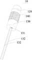
请参阅图1-图2。图1是本申请提供的一种发热体一实施例的结构示意图;图2是图1所示发热体的爆炸图的结构示意图。See Figures 1-2. FIG. 1 is a schematic structural diagram of an embodiment of a heating element provided by the present application; FIG. 2 is a schematic structural diagram of an exploded view of the heating element shown in FIG. 1 .
发热体10包括加热件110、第一固定件120以及第二固定件130。The
加热件110可以是线性发热单元,例如可以采用一根发热丝采用预设轨迹进行弯折后形成;或者加热件110也可以呈网状,其可以采用线性发热丝等编制形成。The
其中,加热件110的两端分别与第一固定件120和第二固定件130固定连接,具体的,加热件110的相对两端可以分别埋设于第一固定件120和第二固定件130内,使得加热件110与第一固定件120和第二固定件130固定。加热件110的中间区域则暴露于第一固定件120和第二固定件130之间。Wherein, both ends of the
加热件110位于第一固定件120和第二固定件130之间的区域用于与预设的导液件(如后文所述的导液棉140)相接触。其中,导液件可以与雾化液接触,以将雾化液导至加热件110的表面,从而可以提高雾化液导向加热件110表面的速率,提高用户吸食时的及时性,提高用户体验。The area of the
本实施例中,加热件110的两端可以与第一固定件120和第二固定件130烧结固定。In this embodiment, both ends of the
具体的,可以先采用将预设的粉状料(或者浆料)形成第一固定件120和第二固定件130的胚料,然后将加热件110的两端分别埋入该到第一固定件120和第二固定件130的胚料中,通过加热烧结,从而使得加热件110的两端可以与第一固定件120和第二固定件130紧密结合。Specifically, a preset powdery material (or slurry) may be used to form the blanks of the first fixing
可选地,为了提高发热体10的整体强度,且降低制造难度,还可以在第一固定件120和第二固定件130之间设置连接件150,其中,连接件150的两端分别与第一固定件120和第二固定件130固定连接。Optionally, in order to improve the overall strength of the
其中,连接件150可以与第一固定件120和第二固定件130一次烧结成型。Wherein, the connecting
进一步的,本实施例中,加热件110位于第一固定件120和第二固定件130之间的部分可以包括多个间隔设置的发热段111,每一发热段111的相对两端均分别与第一固定件120和第二固定件130连接。Further, in this embodiment, the portion of the
其中,在第一固定件120和第二固定件130上分别开设有第一通孔121和第二通孔131。本实施例中,间隔设置的多个发热段111的各一端可以环绕第一通孔121设置,隔设置的多个发热段111的各另一端可以环绕第二通孔131设置。Wherein, a first through
隔设置的多个发热段111可以环绕形成雾化空间101,第一通孔121和第二通孔131则与该雾化空间101相连通。A plurality of
本方案中,第一通孔121和第二通孔131二者中的一者可以与吸气通路连通,通孔121和第二通孔131二者中的另一者与进气通路连通。因此,当多个发热段111对雾化液进行加热雾化,形成的气雾则可以穿过多个发热段111之间的间隙而进入到雾化空间101,用户可以自吸气通路吸气,从而使得外界空气可以自进气通路进入雾化空间101,且形成气流,气流可以带动形成的气雾自吸气通路被吸出食用。In this solution, one of the first through
因此,本申请的方案中,通过预设导液件(如后文所述的导液棉140)将雾化液导至加热件110表面,可以加快雾化液流向加热件110表面,确保雾化液形成气雾的即时性,提高用户体验。另外,通过将多个间隔发热段111且环绕设置,进而采用预设的导液件与多个发热段111接触,以将雾化液导入多个发热段111的表面,从而可以提高雾化液的下液速率,提高气雾形成的速率。Therefore, in the solution of the present application, the atomized liquid is guided to the surface of the
本实施例,当加热件110为通过发热丝进行弯折后形成时,多个发热段111均为直线段。In this embodiment, when the
或者在其他的实施方式中,加热件110也可以呈网状,即,相邻的两个发热段111均之间可以通过至少一子发热段112连接。此方案中,子发热段112的数量为多个,多个发热段111和多个子发热段112可以形成网状的加热件110。Or in other embodiments, the
本实施例中,可选地,部分发热段111可以埋设于连接件150内。其中,连接件150的宽度为0.5-2mm,具体的,连接件150可以呈长条状且其截面为弧形,对应的连接件150宽度则对应为该弧形的弧长。其中连接件150宽度可以1为0.5、1、1.5或者2mm。本实施例,通过将连接件150的宽度限定为在0.5-2mm的范围内,可以在确保连接件150的强度的情况下,减小连接件150与导液棉的接触面积,即,可以提高多个发热段111暴露于连接件150外的面积,从而可以确保加热件110与导液棉的接触面积。In this embodiment, optionally, part of the
在其他的实施方式中,连接件150可以为连接管,多个发热段111可以嵌设在该连接管的外侧,其中,在连接管上设置有多个开孔,通过发热段111加热形成的气雾可以通过连接件150上的开孔进入连接件150的内部空间(此时,连接件150的内部空间则可以构成如前文所述的雾化空间101)。In other embodiments, the connecting
第二固定件130上设置有至少两个电极132;两个电极132的各一端分别与加热件110的不同位置连接,两个电极132的各另一端分别用于与外界电源的正负极电连接。The
其中,可选地,两个电极132可以与加热件110一体设置,即,两个电极132与加热件110为一体结构,加热件110的一端贯穿第二固定件130后形成两个间隔设置的电极132。Wherein, optionally, the two
进一步的,本实施例中,第一固定件120和第二固定件130二者均可以呈圆柱体(或者近似呈圆柱体),二者的直径可以相等。第一固定件120和第二固定件130二者的轴线则可以共线。Further, in this embodiment, both the first fixing
或者,在其他的实施例中,第一固定件120和第二固定件130二者的截面可以是椭圆形、正方形或者矩形等,二者的截面形状及尺寸可以设置为相同。Alternatively, in other embodiments, the cross-sections of the first fixing
上述实施例中,需要采用导液件与第一固定件120和第二固定件130之间的发热段111相接触。其中为了安装方便,还可以在第一固定件120和第二固定件130之间的发热段111直接套设导液件。In the above embodiment, it is necessary to use the liquid conducting member to contact the
具体请参阅图1、图3和图4。图3是本申请提供的一种发热体组件一实施例的结构示意图;图4是图3所示发热体组件的剖视图。Please refer to Figure 1, Figure 3 and Figure 4 for details. FIG. 3 is a schematic structural diagram of an embodiment of a heating element assembly provided by the present application; FIG. 4 is a cross-sectional view of the heating element assembly shown in FIG. 3 .
其中,发热体组件包括导液棉140和如前文所述的发热体10。其中,导液棉140呈环状,导液棉140套设于位于第一固定件120和第二固定件130之间的多个发热段111上。且,导液棉140的外壁可以设置为与第一固定件120及第二固定件130的侧壁相平齐。Wherein, the heating element assembly includes the liquid-conducting
或者,在其他的实施例中,导液棉140的外侧壁可以设置为部分超出第一固定件120和第二固定件130形成的槽部。Alternatively, in other embodiments, the outer side wall of the liquid-conducting
导液棉140的相对两端分别与第一固定件120和第二固定件130相接触。The opposite ends of the liquid-conducting
进一步的,基于同样的发明构思,本申请还提供了一种雾化芯。Further, based on the same inventive concept, the present application also provides an atomizing core.
请参阅图5,图5是本申请提供的一种雾化芯一实施例的结构示意图。Please refer to FIG. 5 , which is a schematic structural diagram of an embodiment of an atomizing core provided by the present application.
其中,雾化芯20包括雾化芯主体、导液棉140和如前文所述的发热体10。或者雾化芯20包括雾化芯主体和如前文所述的发热体组件。Wherein, the
雾化芯主体中可以形成用于容置雾化液的储液腔201。其中,雾化芯主体包括第一套管210、第二套管220、第一密封件230、第二密封件240。储液腔201可以通过一套管210、第二套管220、第一密封件230、第二密封件240以及导液棉140、发热体10围设形成,从而可以使得形成的雾化芯20结构简单且降低安装难度。A
其中,储液腔201具有出液口,导液棉140则可以盖设于该出液口的位置。导液棉140的外壁朝向储液腔201的出液口设置,从而使得导液棉140可以接收储液腔201中的雾化液。The
其中,可选地,导液棉140和发热体10形成的发热体组件可以封盖该储液腔201的出液口,从而避免储液腔201中的雾化液漏液。Wherein, optionally, the heating element assembly formed by the liquid-conducting
进一步的,本实施例,第二套管220的截面尺寸大于第一套管210的截面尺寸。第二套管220套设于第一套管210上,第二套管220的相对两端分别与第一密封件230和第二密封件240连接。即,第一密封件230和第二密封件240可以分别封盖与第二套管220相对两端的开口上,从而形成一容置空间,第一套管210和发热体10均位于该容置空间内。Further, in this embodiment, the cross-sectional size of the
进一步的,第一套管210的一端可以套设于发热体10中的第一固定件120上且第一套管210的内部管道可以与发热体10中的雾化空间101相连通;第一套管210的另一端则与第一密封件230相连接,且第一密封件230上开设有出气孔231,第一套管210的另一端的开口与出气孔231相连通。Further, one end of the
发热体10中的第二固定件130则可以与第二密封件240连接。其中,在第二密封件240上设置有进气孔241,进气孔241可以用于与外界大气连通,当第二固定件130对于第二密封件240固定连接时,第二固定件130的第二通孔131可以与进气孔241相连通,从而可以使得外界大气可以经过进气孔241沿第二通孔131进入雾化空间101。The
因此,导液棉140可以将储液腔201中的雾化液导至发热段111表面,使得雾化液形成气雾,气雾可以自雾化空间101中依次沿第一套管210的内管及出气孔231被抽吸除供用户进行吸食。Therefore, the liquid-conducting
可选地,在储液腔201中设置有储液棉202,导液棉140可以与储液棉202相接触。其中,储液棉202可以呈海绵状以用于存储雾化液,且储液棉202的外轮廓可以与储液腔201的内壁相匹配。Optionally, a
请进一步参阅图5,其中,在第一密封件230上设置有凸台部232,出气孔231则可以开设于该凸台部232上,且第一固定件120上还设有凸起122。第一套管210的一端可以套设于凸起122上,另一端则可以套设于凸台部232上。Please further refer to FIG. 5 , wherein the
其中,在第一套管210与凸起122及与凸台部232的连接处,可以设置密封结构,以确保储液腔201的密封性能,避免储液腔201漏液。Wherein, a sealing structure may be provided at the connection between the
进一步的,在第一密封件230背离第二密封件240的一侧设置有第一凹槽,该凹槽中可以设置吸液棉233,吸液棉233可以环绕出气孔231设置,从而可以吸收出气孔231处的气雾的冷凝液,从而可以避免在出气孔231的位置发生冷凝液漏液。Further, a first groove is provided on the side of the
与之对应的,在第二密封件240背离第一密封件230的一侧同样可以设置吸液棉242,吸液棉242可以吸收第二通孔131处的气雾的冷凝液,从而可以避免在第二通孔131的位置发生冷凝液漏液。Correspondingly, a liquid-absorbing
请进一步参阅图6。图6是图5所示雾化芯另一实施方式的结构示意图。Please refer further to Figure 6. FIG. 6 is a schematic structural diagram of another embodiment of the atomizing core shown in FIG. 5 .
本实施方式中,雾化芯20还包括转接件250,转接件250可以与第二密封件240相连接,其中,在转接件250朝向第二密封件240的一侧具有第二凹槽,且吸液棉242可以安装在该第二凹槽内。In this embodiment, the
进一步的,基于同样的发明构思,本申请还提供了一种雾化器。请参阅图7,图7是本申请提供的一种雾化器一实施例的结构示意图。Further, based on the same inventive concept, the present application also provides an atomizer. Please refer to FIG. 7 , which is a schematic structural diagram of an embodiment of an atomizer provided by the present application.
雾化器30包括主体部310和如前文所的雾化芯20。The atomizer 30 includes a
其中,主体部310中设置有电源311,雾化芯20安装于主体部310内,且电源311与发热体10电连接。The
其中,可选地,主体部310中还设置有耦接的控制器312和气压检测装置(图中未示出);控制器312与电源311电连接,气压检测装置用于对第一套管210内的气压进行检测,且控制器312在第一套管210内的气压达到预设值时控制电源311对发热体10供电。Wherein, optionally, the
其中,主体部310包括可拆卸连接的第一壳体301和第二壳体302,第一壳体301和第二壳体302可以围设成安装空间,电源311、控制器312、气压检测装置以及雾化芯20均安装在该安装空间内。The
其中,电源311和控制器312可以设置在第一壳体301内,第二壳体302的端部为吸嘴部303,吸嘴部303上具有吸气通道3031,吸气通道3031与出气孔231相连通。The
因此,用户可以自吸嘴部303处吸气,从而将雾化空间101中的气雾沿第一套管210、出气孔231以及吸气通道3031吸出。Therefore, the user can inhale from the
本实施例中,通过设置控制器312和气压检测装置中,在用户自吸嘴部303处吸气时,可以使得第一套管210及其连接的雾化空间101中的气压减小,根据此原理。通过气压检测装置对第一套管210和/或雾化空间101中的气压进行检测,当检测到第一套管210和/或雾化空间101中的气压小于预设值时,则可以表明用户开始了吸气动作,则此时气压检测装置会向控制器312发出触发信号,使得控制器312控制电源311向发热体10供电,使得雾化液被加热形成气雾,以供用户进行吸食。In this embodiment, by setting the
而当用户停止吸气时,第一套管210和/或雾化空间101中的气压会恢复至初始值(例如大气压值),此时,若气压检测装置检测到,第一套管210和/或雾化空间101中的气压恢复到初始值,则可以向控制器312发出触发信号,使得控制器312能控制电源311停止向发热体10供电。When the user stops inhaling, the air pressure in the
综上,本领域技术人员容易理解,本申请的有益效果是:本申请的方案中,通过采用导液棉与雾化液,以将雾化液导至加热件的表面,从而可以提高雾化液导向加热件表面的速率,提高用户吸食时的及时性,提高用户体验。另外,采用储液棉进行存储雾化液,且通过导液棉与储液棉接触,从而可以将储液棉中存储的雾化液导至加热件表面,在确保雾化液导向加热件表面的速率的情况下,还可以减小雾化液漏液风险。另外,本申请方案提供的雾化芯结构简单,其生产加工及安装过程均简单方便,可以提供生产效率。To sum up, those skilled in the art can easily understand that the beneficial effects of the present application are: in the solution of the present application, by using liquid-conducting cotton and atomizing liquid to guide the atomizing liquid to the surface of the heating element, the atomization can be improved. The speed at which the liquid is guided to the surface of the heating element improves the timeliness of the user's smoking and improves the user experience. In addition, the liquid storage cotton is used to store the atomized liquid, and the liquid guiding cotton is in contact with the liquid storage cotton, so that the atomized liquid stored in the liquid storage cotton can be led to the surface of the heating element, and the atomized liquid can be guided to the surface of the heating element. In the case of a high rate, the risk of leakage of the atomized liquid can also be reduced. In addition, the atomizing core provided by the solution of the present application has a simple structure, and the production, processing and installation processes thereof are simple and convenient, and the production efficiency can be improved.
以上所述仅为本申请的实施例,并非因此限制本申请的专利范围,凡是利用本申请说明书及附图内容所作的等效结构或等效流程变换,或直接或间接运用在其他相关的技术领域,均同理包括在本申请的专利保护范围内。The above are only the embodiments of the present application, and are not intended to limit the scope of the patent of the present application. Any equivalent structure or equivalent process transformation made by using the contents of the description and drawings of the present application, or directly or indirectly applied to other related technologies Fields are similarly included within the scope of patent protection of this application.
Claims (12)
Priority Applications (1)
| Application Number | Priority Date | Filing Date | Title |
|---|---|---|---|
| CN202210089855.0ACN114557484A (en) | 2022-01-25 | 2022-01-25 | A heating element, atomizing core and atomizer |
Applications Claiming Priority (1)
| Application Number | Priority Date | Filing Date | Title |
|---|---|---|---|
| CN202210089855.0ACN114557484A (en) | 2022-01-25 | 2022-01-25 | A heating element, atomizing core and atomizer |
Publications (1)
| Publication Number | Publication Date |
|---|---|
| CN114557484Atrue CN114557484A (en) | 2022-05-31 |
Family
ID=81714654
Family Applications (1)
| Application Number | Title | Priority Date | Filing Date |
|---|---|---|---|
| CN202210089855.0APendingCN114557484A (en) | 2022-01-25 | 2022-01-25 | A heating element, atomizing core and atomizer |
Country Status (1)
| Country | Link |
|---|---|
| CN (1) | CN114557484A (en) |
Cited By (2)
| Publication number | Priority date | Publication date | Assignee | Title |
|---|---|---|---|---|
| CN116326844A (en)* | 2023-03-28 | 2023-06-27 | 爱奇迹(香港)有限公司 | Atomizing core and atomizing device |
| WO2024016126A1 (en)* | 2022-07-18 | 2024-01-25 | 深圳市华诚达精密工业有限公司 | Atomization device and atomizer |
Citations (4)
| Publication number | Priority date | Publication date | Assignee | Title |
|---|---|---|---|---|
| CN205728069U (en)* | 2016-05-27 | 2016-11-30 | 深圳市合元科技有限公司 | Nebulizer and the electronic cigarette of this nebulizer of application |
| WO2020038183A1 (en)* | 2018-08-24 | 2020-02-27 | 深圳市康泓威科技有限公司 | Electronic cigarette having analog air pressure sensor and control method therefor |
| CN112315027A (en)* | 2020-08-31 | 2021-02-05 | 深圳麦克韦尔科技有限公司 | Electronic atomization device and atomizer and atomization core thereof |
| CN215303006U (en)* | 2021-01-28 | 2021-12-28 | 深圳雪雾科技有限公司 | Atomizing core, atomizer and electronic atomization device |
- 2022
- 2022-01-25CNCN202210089855.0Apatent/CN114557484A/enactivePending
Patent Citations (4)
| Publication number | Priority date | Publication date | Assignee | Title |
|---|---|---|---|---|
| CN205728069U (en)* | 2016-05-27 | 2016-11-30 | 深圳市合元科技有限公司 | Nebulizer and the electronic cigarette of this nebulizer of application |
| WO2020038183A1 (en)* | 2018-08-24 | 2020-02-27 | 深圳市康泓威科技有限公司 | Electronic cigarette having analog air pressure sensor and control method therefor |
| CN112315027A (en)* | 2020-08-31 | 2021-02-05 | 深圳麦克韦尔科技有限公司 | Electronic atomization device and atomizer and atomization core thereof |
| CN215303006U (en)* | 2021-01-28 | 2021-12-28 | 深圳雪雾科技有限公司 | Atomizing core, atomizer and electronic atomization device |
Cited By (2)
| Publication number | Priority date | Publication date | Assignee | Title |
|---|---|---|---|---|
| WO2024016126A1 (en)* | 2022-07-18 | 2024-01-25 | 深圳市华诚达精密工业有限公司 | Atomization device and atomizer |
| CN116326844A (en)* | 2023-03-28 | 2023-06-27 | 爱奇迹(香港)有限公司 | Atomizing core and atomizing device |
Similar Documents
| Publication | Publication Date | Title |
|---|---|---|
| EP3287020B1 (en) | Electronic cigarette | |
| CN110447970B (en) | Electronic atomizing device and atomizer thereof | |
| CN217826736U (en) | Atomizer and electronic atomization device | |
| CN211482973U (en) | Atomization component and electronic cigarette | |
| CN213819836U (en) | Atomizer and electronic atomization device | |
| CN111011930B (en) | Electronic atomization device and atomizer thereof | |
| CN216019105U (en) | Atomizing core, atomizer and electronic atomization device | |
| CN116807059A (en) | Atomizer and electronic atomization device | |
| CN114557484A (en) | A heating element, atomizing core and atomizer | |
| WO2021258807A1 (en) | Disposable electronic atomization device with liquid injection before sale | |
| CN216019106U (en) | Atomizing core, atomizer and electronic atomization device | |
| CN113287790A (en) | Electronic atomization device and atomization device thereof | |
| WO2017190335A1 (en) | Electronic cigarette | |
| CN114259091A (en) | Atomization structure, atomizer and aerosol generating device | |
| CN212590242U (en) | Electronic atomization device and atomizer thereof | |
| CN218303435U (en) | Electronic atomization device and atomizer thereof | |
| CN217986669U (en) | Electronic atomization device and atomizer thereof | |
| CN114190594B (en) | Atomization structure, atomization device and aerosol generation device | |
| CN116406826A (en) | Atomizer and electronic atomizing device | |
| CN111011929B (en) | Electronic atomization device and atomizer thereof | |
| CN218790514U (en) | Atomizer and electronic atomization device | |
| CN114073335A (en) | Atomizing core and atomizer applying same | |
| CN217851361U (en) | Heat-generating body subassembly, atomizing core and atomizer | |
| CN215347019U (en) | Atomizer and aerosol generating device | |
| CN216821778U (en) | Electronic atomization device |
Legal Events
| Date | Code | Title | Description |
|---|---|---|---|
| PB01 | Publication | ||
| PB01 | Publication | ||
| SE01 | Entry into force of request for substantive examination | ||
| SE01 | Entry into force of request for substantive examination |