CN114555176A - body electrode unit - Google Patents
body electrode unitDownload PDFInfo
- Publication number
- CN114555176A CN114555176ACN202080070249.3ACN202080070249ACN114555176ACN 114555176 ACN114555176 ACN 114555176ACN 202080070249 ACN202080070249 ACN 202080070249ACN 114555176 ACN114555176 ACN 114555176A
- Authority
- CN
- China
- Prior art keywords
- electrode
- attached
- release sheet
- connection portion
- body electrode
- Prior art date
- Legal status (The legal status is an assumption and is not a legal conclusion. Google has not performed a legal analysis and makes no representation as to the accuracy of the status listed.)
- Pending
Links
Images


Classifications
- A—HUMAN NECESSITIES
- A61—MEDICAL OR VETERINARY SCIENCE; HYGIENE
- A61B—DIAGNOSIS; SURGERY; IDENTIFICATION
- A61B5/00—Measuring for diagnostic purposes; Identification of persons
- A61B5/05—Detecting, measuring or recording for diagnosis by means of electric currents or magnetic fields; Measuring using microwaves or radio waves
- A61B5/053—Measuring electrical impedance or conductance of a portion of the body
- A—HUMAN NECESSITIES
- A61—MEDICAL OR VETERINARY SCIENCE; HYGIENE
- A61N—ELECTROTHERAPY; MAGNETOTHERAPY; RADIATION THERAPY; ULTRASOUND THERAPY
- A61N1/00—Electrotherapy; Circuits therefor
- A61N1/02—Details
- A61N1/04—Electrodes
- A61N1/0404—Electrodes for external use
- A61N1/0472—Structure-related aspects
- A61N1/0492—Patch electrodes
- A61N1/0496—Patch electrodes characterised by using specific chemical compositions, e.g. hydrogel compositions, adhesives
- A—HUMAN NECESSITIES
- A61—MEDICAL OR VETERINARY SCIENCE; HYGIENE
- A61B—DIAGNOSIS; SURGERY; IDENTIFICATION
- A61B5/00—Measuring for diagnostic purposes; Identification of persons
- A61B5/68—Arrangements of detecting, measuring or recording means, e.g. sensors, in relation to patient
- A61B5/6801—Arrangements of detecting, measuring or recording means, e.g. sensors, in relation to patient specially adapted to be attached to or worn on the body surface
- A61B5/683—Means for maintaining contact with the body
- A61B5/6832—Means for maintaining contact with the body using adhesives
- A61B5/68335—Means for maintaining contact with the body using adhesives including release sheets or liners
- A—HUMAN NECESSITIES
- A61—MEDICAL OR VETERINARY SCIENCE; HYGIENE
- A61B—DIAGNOSIS; SURGERY; IDENTIFICATION
- A61B5/00—Measuring for diagnostic purposes; Identification of persons
- A61B5/24—Detecting, measuring or recording bioelectric or biomagnetic signals of the body or parts thereof
- A61B5/25—Bioelectric electrodes therefor
- A61B5/251—Means for maintaining electrode contact with the body
- A61B5/257—Means for maintaining electrode contact with the body using adhesive means, e.g. adhesive pads or tapes
- A—HUMAN NECESSITIES
- A61—MEDICAL OR VETERINARY SCIENCE; HYGIENE
- A61N—ELECTROTHERAPY; MAGNETOTHERAPY; RADIATION THERAPY; ULTRASOUND THERAPY
- A61N1/00—Electrotherapy; Circuits therefor
- A61N1/18—Applying electric currents by contact electrodes
- A61N1/32—Applying electric currents by contact electrodes alternating or intermittent currents
- A61N1/36—Applying electric currents by contact electrodes alternating or intermittent currents for stimulation
- A61N1/36014—External stimulators, e.g. with patch electrodes
- A—HUMAN NECESSITIES
- A61—MEDICAL OR VETERINARY SCIENCE; HYGIENE
- A61B—DIAGNOSIS; SURGERY; IDENTIFICATION
- A61B2562/00—Details of sensors; Constructional details of sensor housings or probes; Accessories for sensors
- A61B2562/02—Details of sensors specially adapted for in-vivo measurements
- A61B2562/0209—Special features of electrodes classified in A61B5/24, A61B5/25, A61B5/283, A61B5/291, A61B5/296, A61B5/053
Landscapes
- Health & Medical Sciences (AREA)
- Life Sciences & Earth Sciences (AREA)
- Animal Behavior & Ethology (AREA)
- Veterinary Medicine (AREA)
- Engineering & Computer Science (AREA)
- Biomedical Technology (AREA)
- Public Health (AREA)
- General Health & Medical Sciences (AREA)
- Biophysics (AREA)
- Heart & Thoracic Surgery (AREA)
- Surgery (AREA)
- Physics & Mathematics (AREA)
- Molecular Biology (AREA)
- Medical Informatics (AREA)
- Pathology (AREA)
- Nuclear Medicine, Radiotherapy & Molecular Imaging (AREA)
- Radiology & Medical Imaging (AREA)
- Chemical & Material Sciences (AREA)
- Chemical Kinetics & Catalysis (AREA)
- General Chemical & Material Sciences (AREA)
- Electrotherapy Devices (AREA)
- Measurement And Recording Of Electrical Phenomena And Electrical Characteristics Of The Living Body (AREA)
Abstract
Translated fromChinese
Description
Translated fromChinese技术领域technical field
本公开的主题涉及体电极单元,其被配置为用于测量生理信息。The presently disclosed subject matter relates to body electrode units configured for measuring physiological information.
背景技术Background technique
现有技术的体电极设置为处于设置有粘合凝胶的面贴附到剥离片的状态下。当使用体电极时,体电极从剥离片剥离,设置有粘合凝胶的面贴附到身体。The body electrode of the related art is provided in a state in which the surface provided with the adhesive gel is attached to the release sheet. When the body electrode is used, the body electrode is peeled off from the release sheet, and the face provided with the adhesive gel is attached to the body.
体电极可以具有安装在可分离成多个区域的基板片上的多个电极(参见例如专利文献JP2007-050033A)。在这样的体电极中,电极被放在一起以形成单个连续形状,并且基板片被附接到多个衬垫。因此,当剥离多个衬垫时,放置在一起以形成单个连续形状的电极能够一次性地附接到身体。与其中电极逐一附接的示例相比,能够容易地执行附接。The body electrode may have a plurality of electrodes mounted on a substrate sheet that can be separated into a plurality of regions (see, eg, Patent Document JP2007-050033A). In such a bulk electrode, the electrodes are brought together to form a single continuous shape, and the substrate sheet is attached to multiple pads. Thus, when multiple liners are peeled off, electrodes placed together to form a single continuous shape can be attached to the body in one go. Compared with the example in which the electrodes are attached one by one, the attachment can be easily performed.
然而,当一次性地将现有技术的体电极的多个电极附接到身体时,基板片可能附接到非预期位置,这可能导致体电极的故障。However, when multiple electrodes of the prior art body electrode are attached to the body at one time, the substrate sheet may be attached to an unintended location, which may lead to failure of the body electrode.
发明内容SUMMARY OF THE INVENTION
本公开的主题的示例性方面提供了一种体电极单元,其具有放置在一起以形成单个连续形状的多个电极,利用该体电极单元,每个电极能够附接到身体上的预期位置。An exemplary aspect of the presently disclosed subject matter provides a body electrode unit having a plurality of electrodes placed together to form a single continuous shape, with which each electrode can be attached to a desired location on the body.
根据当前公开的主题的一个方面,体电极单元包括:体电极,其被配置为附接到身体;以及体电极附接到的剥离片。所述体电极至少包括第一电极和第二电极。第一电极和第二电极被放置在一起以形成单个连续形状。所述剥离片包括第一加工部,该第一加工部被配置为促进所述剥离片的分离和弯曲中的至少一者,所述第一加工部设置在所述第一电极所附接的位置与所述第二电极所附接的位置之间的第一区域中。According to one aspect of the presently disclosed subject matter, a body electrode unit includes: a body electrode configured to be attached to a body; and a release sheet to which the body electrode is attached. The body electrode includes at least a first electrode and a second electrode. The first electrode and the second electrode are placed together to form a single continuous shape. The release sheet includes a first machined portion configured to facilitate at least one of separation and bending of the release sheet, the first machined portion being provided on a surface to which the first electrode is attached. in the first region between the location and the location to which the second electrode is attached.
附图说明Description of drawings
图1A是示出了体电极的正面的视图。FIG. 1A is a view showing the front side of the body electrode.
图1B是示出了体电极的背面的视图。FIG. 1B is a view showing the back surface of the body electrode.
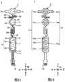
图2A是示出了体电极单元的视图。FIG. 2A is a view showing a body electrode unit.
图2B是示出了体电极单元的另一视图。FIG. 2B is another view showing the body electrode unit.
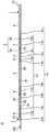
图3是示出了体电极单元的侧面的视图。FIG. 3 is a view showing a side surface of the body electrode unit.
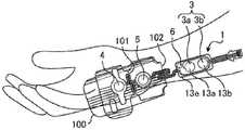
图4A是示出如何使用体电极单元的视图。FIG. 4A is a view showing how the body electrode unit is used.
图4B是示出如何使用体电极单元的另一视图。FIG. 4B is another view showing how the body electrode unit is used.
图4C是示出如何使用体电极单元的另一视图。FIG. 4C is another view showing how the body electrode unit is used.
图4D是示出如何使用体电极单元的另一视图。FIG. 4D is another view showing how the body electrode unit is used.
图5A是示出如何使用体电极单元的另一视图。FIG. 5A is another view showing how the body electrode unit is used.
图5B是示出如何使用体电极单元的另一视图。FIG. 5B is another view showing how the body electrode unit is used.
图5C是示出如何使用体电极单元的另一视图。FIG. 5C is another view showing how the body electrode unit is used.
图5D是示出如何使用体电极单元的另一视图。FIG. 5D is another view showing how the body electrode unit is used.
图6A是示出第一连接部和第二连接部的示例的视图。FIG. 6A is a view showing an example of a first connection part and a second connection part.
图6B是示出第一连接部和第二连接部的另一示例的视图。FIG. 6B is a view showing another example of the first connection part and the second connection part.
图6C是示出第一连接部和第二连接部的另一示例的视图。FIG. 6C is a view showing another example of the first connection part and the second connection part.
图7A是示出中性电极的示例的视图。FIG. 7A is a view showing an example of a neutral electrode.
图7B是示出中性电极的示例的另一视图。FIG. 7B is another view showing an example of the neutral electrode.
具体实施方式Detailed ways
在下文中,将参考附图描述当前公开的主题的实施例。Hereinafter, embodiments of the presently disclosed subject matter will be described with reference to the accompanying drawings.
体电极1的结构Structure of
首先,将参考图1A和图1B描述体电极1的结构。图1A是体电极1的正面图,且图1B是体电极1的背面图。First, the structure of the
在该示例中,体电极1用于刺激通向身体(体电极1所附接到的受试者)的肌肉的神经,并且基于肌肉的生理信号来监测反应肌肉的松弛程度。例如,在身体的肌肉的松弛程度由TOF(四联刺激)方法监测的情况下使用体电极1,在该TOF方法中,每0.5秒连续执行四次肌肉刺激,并且每15秒重复四次连续肌肉刺激的过程。In this example, the
刺激电极3、有源电极4、基准电极5和中性电极6安装在基部2上。基部2包括:上岛部2a,基准电极5安装在该上岛部2a上;中间岛部2b,有源电极4安装在该中间岛部2b上;下岛部2c,刺激电极3和中性电极6安装在该下岛部2c上;第一连接部2d,其设置在中间岛部2b与下岛部2c之间;以及第二连接部2e,其设置在上岛部2a与中间岛部2b之间。The
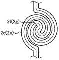
第一连接部2d具有第一方向改变部2f,该第一方向改变部2f被配置为改变第一连接部2d延伸的方向。由于第一连接部2d具有第一方向改变部2f,因此刺激电极3与有源电极4之间的距离和角度中的至少一者是可调节的。The
第二连接部2e具有第二方向改变部2g,该第二方向改变部2g被配置为改变第二连接部2e延伸的方向。由于第二连接部2e具有第二方向改变部2g,因此有源电极4与基准电极5之间的距离和角度中的至少一者是可调节的。The
第一方向改变部2f被配置为在体电极1的长度方向上改变第一连接部2d延伸的方向。第二方向改变部2g被配置为在体电极1的横向方向上改变第二连接部2e延伸的方向。也就是说,第一方向改变部2f和第二方向改变部2g被配置为分别在不同方向上改变第一连接部2d延伸的方向和第二连接部2e延伸的方向。The first
第一方向改变部2f被配置为在体电极1的长度方向上改变第一连接部2d延伸的方向,以防止当将体电极1附接到受试者时,第一连接部2d竖起并接触受试者的手腕而刺激产生疼痛的感觉。The first
第二方向改变部2g被配置为在体电极1的横向方向上改变第二连接部2e延伸的方向,以防止当将体电极1附接到受试者时,第二连接部2e竖起并接触小鱼际而刺激产生疼痛的感觉。The second
刺激电极3设置在体电极1的长度方向上的与基准电极5相比更靠近连接器12的位置处,并且被配置为向通向身体的肌肉的神经(例如,尺骨神经)施加电刺激。刺激电极3包括负电极3a和正电极3b。The
有源电极4设置在刺激电极3与基准电极5之间,并且设置为检测对由刺激电极3施加的电刺激响应的来自肌肉的生理信号。在该实施例中,有源电极4由阴极配置。这里,有源电极4对应于例如小指外展肌而安装。The
基准电极5被设置在体电极2的长度方向上的与刺激电极3和有源电极4相比远离连接器12的位置处,并且被配置为检测对由刺激电极3施加的电刺激响应的来自肌肉的生理信号。在本实施例中,基准电极5是正电极。这里,基准电极5对应于例如小指外展肌而安装。The
中性电极6被设置为阻挡流过体电极1的噪声。中性电极6设置在负电极3a的近侧。因此,在负电极3a和有源电极4彼此靠近的情况下产生的噪声容易被阻挡。The
负电极布线部7设置为将负电极3a与连接器12彼此连接。因此,基于对电刺激器(未示出)执行的操作,负电极3a通过负电极布线部7向身体施加刺激。The negative
正电极布线部8设置为将正电极3b与连接器12彼此连接。因此,基于对电刺激器执行的操作,正电极3b通过正电极布线部8向身体施加刺激。The positive
有源电极布线部9设置为将有源电极4与连接器12彼此连接。因此,基于活体的生理信号的检测,有源电极4通过有源电极布线部9将生理信号输出到电刺激器。有源电极布线部9的一部分布置在第一连接部2d中。The active electrode wiring portion 9 is provided to connect the
基准电极布线部10设置为将基准电极5与连接器12彼此连接。因此,基于对活体的生理信号的检测,基准电极5通过基准电极布线部10将生理信号输出到电刺激器。基准电极布线部10的一部分布置在第二连接部2e中。The reference
中性电极布线部11设置为将中性电极6与连接器12彼此连接。The neutral
连接器12设置为将分别与电极连接的布线部连接。具体地,连接至负电极3a的负电极布线部7、连接至正电极3b的正电极布线部8、连接至有源电极4的有源电极布线部9、连接至基准电极5的基准电极布线部10以及连接至中性电极6的中性电极布线部11连接到连接器12。连接器12进一步连接到电刺激器。未连接到任何布线部的备用连接部件设置在连接器12中。The
粘合凝胶13设置为将电极附接到身体,并且覆盖电极的背面。具体地,粘合凝胶13包括:覆盖负电极3a的背面的负电极粘合凝胶13a、覆盖正电极3b的背面的正电极粘合凝胶13b、覆盖有源电极4的背面的有源电极粘合凝胶13c、覆盖基准电极5的背面的基准电极粘合凝胶13d以及覆盖中性电极6的背面的中性电极粘合凝胶13e。
粘合带14设置为将体电极1附接到将稍后描述的剥离片100,并且具有粘合性。如图1B所示,粘合带14具有包括如下部分的构造:刺激电极粘合带14a,其设置在下岛部2c的背面上,并且设置在负电极粘合凝胶13a、正电极3b和中性电极粘合凝胶13e的周围;有源电极粘合带14b,其设置在中间岛部2b的背面上,并且设置在有源电极粘合凝胶13c的周围;以及基准电极粘合带14c,其设置在上岛部2a的背面上,并且设置在基准电极粘合凝胶13d的周围。The
代替粘合带14,例如,可以采用如下配置:其中,浆糊粘附到上岛部2a、中间岛部2b和下岛部2c并且粘附到剥离片100。也就是说,仅需要执行提供具有粘合性的上岛部2a、中间岛部2b和下岛部2c的处理。这里,“粘合性”是指具有部件被贴附并保持到剥离片100或受试者的皮肤上的程度的粘度。Instead of the
粘合带不设置在第一连接部2d的背面上,并且不设置在第二连接部2e的背面上。也就是说,第一连接部2d的背面和第二连接部2e的背面不具有粘合性。因此,当刺激电极粘合带14a、有源电极粘合带14b和基准电极粘合带14c被附接到受试者时,能够防止发生带被附接到非预期位置的情况。The adhesive tape is not provided on the back surface of the
体电极单元UBody electrode unit U
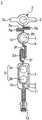
接下来,参考图2A和2B,将描述体电极单元U。图2A是体电极单元U的分解立体图,且图2B是体电极单元U的立体图。Next, referring to FIGS. 2A and 2B , the body electrode unit U will be described. FIG. 2A is an exploded perspective view of the body electrode unit U, and FIG. 2B is a perspective view of the body electrode unit U. FIG.
如图2A所示,体电极单元U具有已经参考图1A和图1B描述的体电极1以及剥离片100。As shown in FIG. 2A , the body electrode unit U has the
剥离片100是体电极1所要附接到的片,并且剥离片100能够透射光。因此,在生产体电极单元U的过程中,容易地检查粘合凝胶13是否被设置为覆盖电极的背面。The
剥离片100具有:上片部100a,上岛部2a的基准电极粘合带14c要被附接到该上片部100a;中间片部100b,中间岛部2b的有源电极粘合带14b被附接到该中间片部100b;以及下片部100c,下岛部2c的刺激电极粘合带14a被附接到该下片部100c。剥离片100包括第一加工部101、第二加工部102、第一凹口103、第二凹口104、圆角部105、定位孔106和图案部107。The
用于促进上片部100a与中间片部100b的分离和/或弯曲的加工被施加到第一加工部101。Processing for promoting separation and/or bending of the
用于促进中间片部100b与下片部100c的分离和/或弯曲的加工被施加到第二加工部102。Processing for promoting separation and/or bending of the middle sheet portion 100b and the
在该实施例中,作为其中剥离片100能够分离和/或弯曲的方式,在第一加工部101和第二加工部102中执行穿孔加工。然而,该方式不限于此,并且可以使用任何方式,只要其能够分离和/或弯曲剥离片100即可。例如,可以将切割剥离片100的厚度的一部分的半切割加工施加到第一加工部101和第二加工部102。具体地,在剥离片100的厚度(例如,约75μm)中,以小于剥离片100的厚度的预定厚度(例如,约50μm)进行切割,从而使得剥离片100能够被分离和/或弯曲。In this embodiment, as a manner in which the
在该实施例中,第一加工部101可以设置在第一区域100d中的任何位置,只要在体电极1附接到剥离片100的情况下,该第一加工部101位于中间岛部2b的下端与下岛部2c的上端之间即可。以相同或类似的方式,第二加工部102可以设置在第二区域100e中的任何位置,只要在体电极1附接到剥离片100的情况下,该第二加工部102位于上岛部2a的下端与中间岛部2b的上端之间即可。In this embodiment, the first processed
第一凹口103设置在第一加工部101的两侧端中。在该实施例中,如图2A和2B所示,第一凹口103具有包括如下部分的构造:第一右凹口103a,其设置在第一加工部101的右侧端部中;以及第一左凹口103b,其设置在第一加工部101的左侧端部中。每个凹口都具有近似半圆形的形状。The
第二凹口104设置在第二加工部102的两侧端中。在该实施例中,如图2A和2B所示,第二凹口104具有包括如下部分的构造:第二右凹口104a,其设置在第二加工部102的右侧端部中;和第二左凹口104b,其设置在第二加工部102的左侧端部中。每个凹口都具有近似半圆形的形状。The
由于设置了第一凹口103,第一加工部101的宽度小于剥离片100的宽度。以相同或类似的方式,由于设置了第二凹口104,因此第二加工部102的宽度小于剥离片100的宽度。因此,能够防止发生如下情况:当上片部100a与中间片部100b沿着第一加工部101彼此分离时或者当中间片部100b与下片部100c沿着第二加工部102彼此分离时,第一连接部2d或第二连接部2e在分离过程中不松弛地拉伸,并且剥离片100不能被切断至端部。Since the
第一凹口103的形状和第二凹口104的形状不限于近似半圆形形状,并且可以是任何形状,只要其能够使第一加工部101的宽度小于剥离片100的宽度,并且第二加工部102的宽度小于剥离片100的宽度即可。The shape of the
圆角部105设置在第一凹口103和第二凹口104的端部处。由于设置了圆角部105,因此此处能够防止发生如下情况:当沿着第一加工部101切断剥离片100时,或者当沿着第二加工部102切断剥离片100时,形成尖锐边缘,并且有人受伤。
定位孔106设置为在用于生产体电极单元U期间固定剥离片100。The positioning holes 106 are provided to fix the
图案部107在剥离片100的长度方向上直线状地设置。由于设置了图案部107,因此当剥离片100是透明的并且掉落到地板上时,剥离片100能够被容易地识别。因此,可以防止有人由于踩在剥离片100上而滑倒。图案部107可以具有任何图案,只要该图案使得能够容易地识别剥离片100即可。The
体电极单元U的侧面Side of body electrode unit U
接下来,参照图3,将描述体电极单元U的侧视图。Next, referring to FIG. 3 , a side view of the body electrode unit U will be described.
如图3所示,体电极1被构造为使得刺激电极3、有源电极4和基准电极5被放在一起以形成单个连续形状。具体地,安装有有源电极4的中间岛部2b与安装有刺激电极3的下岛部2c通过第一连接部2d彼此连接。安装有基准电极5的上岛部2a与安装有有源电极4的中间岛部2b通过第二连接部2e彼此连接。这就是在该示例中如何将刺激电极3、有源电极4和基准电极5放在一起以形成单个连续形状。As shown in Figure 3, the
体电极单元U的使用Use of Body Electrode Unit U
接下来,参照附图4和5,将描述体电极单元U的使用方式。Next, referring to FIGS. 4 and 5 , the usage of the body electrode unit U will be described.
如上所述,将体电极1附接到剥离片100。因此,在使用体电极1的情况下,剥离片100首先在箭头Ar1的方向上移动,如图4A所示,由此解除下片部100c与刺激电极粘合带14a之间的附接。因此,剥离片100在延伸至第二加工部102的范围内剥离。As described above, the
接着,如图4B所示,将剥离片100在箭头Ar2的方向上移动,从而沿着第二加工部102弯曲剥离片100。在第二加工部102由可撕开穿孔构成的情况下,尽管未示出,但是下片部100c可以沿着第二加工部102与剥离片100分离。Next, as shown in FIG. 4B , the
接下来,如图4C所示,附接刺激电极粘合带14a,使得负电极粘合凝胶13a和正电极粘合凝胶13b对应于受试者的尺骨神经。Next, as shown in FIG. 4C, the stimulation electrode
接下来,如图4D所示,将剥离片100在箭头Ar3的方向上移动,由此解除中间片部100b与有源电极粘合带14b之间的附接。因此,剥离片100在延伸至第一加工部101的范围内剥离。Next, as shown in FIG. 4D , the
接下来,如图5A所示,将剥离片100在箭头Ar4的方向上移动,从而沿着第一加工部101弯曲剥离片100。在第一加工部101由可撕开穿孔构成的情况下,尽管未示出,中间片部100b可以沿着第一加工部101与上片部100a分离。Next, as shown in FIG. 5A , the
接下来,如图5B所示,附接有源电极粘合带14b,使得有源电极粘合凝胶13c对应于受试者的小指外展肌。Next, as shown in FIG. 5B, the active electrode
此时,能够改变刺激电极3与有源电极4之间的距离和角度中的至少一者的第一方向改变部2f设置在第一连接部2d中,因此第一连接部2d在箭头Ar5的方向上伸长。At this time, the first
接下来,如图5C所示,将剥离片100在箭头Ar6的方向上移动,由此解除上片部100a与基准电极粘合带14c之间的附接。因此,剥离片100从体电极1剥离。Next, as shown in FIG. 5C , the
接下来,如图5D所示,附接基准电极粘合带14c,使得基准电极粘合凝胶13d对应于受试者的小指外展肌。Next, as shown in FIG. 5D, the reference electrode
此时,至少能够改变有源电极4与基准电极5之间的距离和角度的第二方向改变部2g设置在第二连接部2e中,且因此第二连接部2e在箭头Ar7的方向上伸长。At this time, the second
如上所述,在实施例中,第一方向改变部2f设置在第一连接部2d中,因此,第一连接部2d能够伸长。此外,在实施例中,第二方向改变部2g设置在第二连接部2e中,因此,第二连接部2e能够伸长。因此,在其中刺激电极3、有源电极4和基准电极5被放在一起以形成单个连续形状的体电极1中,即使在受试者具有大手的情况下,安装有刺激电极3的下岛部2c、安装有有源电极4的中间岛部2b以及安装有基准电极5的上岛部2a也能够分别附接到期望的位置。As described above, in the embodiment, the first
由于第一连接部2d能够伸长,并且第二连接部2e能够伸长,所以实施例的体电极1不仅能够在安装有刺激电极3的下岛部2c、安装有有源电极4的中间岛部2b以及安装有基准电极5的上岛部2a附接到受试者的手或者手臂时使用,而且能够在这些部分附接到受试者的脚时使用。Since the first connecting
另一方面,同样在刺激电极3、有源电极4和基准电极5被放在一起以形成单个连续形状的体电极1被用在具有小手的受试者的情况下,存在这样的问题:刺激电极3、有源电极4和基准电极5难以附接到期望的位置。On the other hand, also in the case where the
相比之下,在本实施例中,第一方向改变部2f设置在第一连接部2d中,因此第一连接部2d能够缩短。此外,在本实施例中,第二方向改变部2g设置在第二连接部2e中,因此,第二连接部2e能够缩短。因此,在其中刺激电极3、有源电极4和基准电极5放在一起以形成单个连续形状的体电极1中,即使在受试者具有小手的情况下,安装有刺激电极3的下岛部2a、安装有有源电极4的中间岛部2b以及安装有基准电极5的上岛部2a也能够附接到期望的位置。In contrast, in the present embodiment, the first
在受试者具有小手的情况下,当第一连接部2d通过第一方向改变部2f缩短时,由阴极构成的负电极3a和由阴极构成的有源电极4彼此靠近。因此,可以认为检测到的生理信号由于噪声而不稳定。然而,中性电极6设置在负电极3a的近侧。因此,即使在负电极3a和有源电极4彼此靠近的情况下,也能够有效地阻挡噪声,并且因此能够稳定检测到的生理信号。In the case where the subject has small hands, when the
第一连接部2d和第二连接部2e的示例Example of the
参考图6A至图6C,将描述第一连接部2d和第二连接部2e的其他示例。6A to 6C, other examples of the
图6A示出了第一连接部2d及第二连接部2e的示例。在该示例中,在第一连接部2d和第二连接部2e中,第一方向改变部2f和第二方向改变部2g各自均设置在两个位置处,并且被构造为改变第一连接部2d和第二连接部2e在倾斜方向上延伸的方向。FIG. 6A shows an example of the
图6B示出了第一连接部2d及第二连接部2e的另一示例。在该示例中,在第一连接部2d和第二连接部2e中,第一方向改变部2f和第二方向改变部2g各自设置在六个位置处,并且被构造为在体电极的长度方向上改变第一连接部2d和第二连接部2e。FIG. 6B shows another example of the
图6C示出第一连接部2d及第二连接部2e的另一示例。在该示例中,在第一连接部2d和第二连接部2e中,第一方向改变部2f和第二方向改变部2g各自设置在一个位置处,并且被配置为改变第一连接部2d和第二连接部2e在旋转方向上延伸的方向。FIG. 6C shows another example of the
如上所述,能够适当地设置第一连接部2d通过第一方向改变部2f改变的方向和第二连接部2e通过第二方向改变部2g改变的方向。As described above, the direction in which the
在第一连接部2d中设置的第一方向改变部2f的数量被要求为至少一个,并且可以适当地设置。The number of the first
以相同或类似的方式,在第二连接部2e中设置的第二方向改变部2g的数量被要求为至少一个,并且可以适当地设置。In the same or similar manner, the number of the second
中性电极6的另一示例Another example of
接下来,参考图7A和7B,将描述中性电极6的变形例。Next, with reference to FIGS. 7A and 7B , a modification of the
在上述实施例中,中性电极6设置在负电极3a的近侧。然而,能够适当地设置中性电极6所设置的位置,只要流经体电极1的噪声能够被阻挡即可。在下文中,将描述设置中性电极6的位置的优选示例。In the above-described embodiment, the
如图7A和7B所示,变形例中的中性电极6设置在与刺激电极3相比更靠近连接器12的位置处。相对于连接器12的距离是短的,因此能够缩短中性电极布线部11。因此,能够降低生产成本。As shown in FIGS. 7A and 7B , the
在中性电极6设置在上岛部2a或中间岛部2b中的情况下,中性电极布线部11的一部分必须设置在第一连接部2d或第二连接部2e中,因此需要加厚第一连接部2d或第二连接部2e。因此,生产成本升高与第一连接部2d或第二连接部2e的加厚部分相对应的量。因此,与中性电极6设置在上岛部2a或中间岛部2b中的情况相比,能够降低生产成本。In the case where the
其他示例Other examples
下面将描述其他示例。Other examples will be described below.
在上述实施例的体电极1中,刺激电极3、有源电极4和基准电极5被安装为使得直线连接它们的中心。然而,刺激电极3、有源电极4和基准电极5可以被安装为使得它们在体电极1的横向方向上偏离。In the
在上述实施例的体电极1中,基准电极5安装在上岛部2a中,并且有源电极4安装在中间岛部2b中。可替代地,有源电极4可以安装在上岛部2a上,并且基准电极5可以安装在中间岛部2b上。In the
在上述实施例的体电极1中,负电极3a被布置在相对于正电极3b远离连接器12的位置处,并且正电极3b被布置在相对于负电极3a靠近连接器12的位置处。可替代地,安装正电极3b的位置与安装负电极3a的位置可以互换。In the
尽管在上述实施例中,第一方向改变部2f在体电极1的长度方向上改变第一连接部2d延伸的方向,但是第一连接部2d延伸的方向可以在体电极1的横向方向上改变。同样地,尽管第二方向改变部2g在横向方向上改变第二连接部2e延伸的方向,但是第二连接部2e延伸的方向可以在长度方向上改变。Although the first
尽管在上述实施例中,第一方向改变部2f和第二方向改变部2g分别在不同方向上改变第一连接部2d和第二连接部2e的方向,但第一连接部2d和第二连接部2e的方向可以在相同的方向上改变。Although in the above-described embodiment, the first
尽管在上述实施例中,穿孔加工和半切割加工已经被描述为第一加工部101和第二加工部102的具体示例,但是本公开的主题不限于此。例如,可以应用位点固定加工,其中,第一加工部101和第二加工部102的两端都被位点固定,并且位点固定端彼此分离。或者,可以在第一加工部101和第二加工部102的至少一侧上设置切口。Although in the above-described embodiments, the punching process and the half-cutting process have been described as specific examples of the first processed
尽管在上述实施例中,第一加工部101和第二加工部102采用与剥离片100能够分离和/或弯曲的方式相同的加工,但是部件可以采用不同的加工。例如,第一加工部101可以采用穿孔加工,并且第二加工部102可以采用半切割加工。Although in the above-described embodiment, the
尽管在上述实施例中,第一加工部101和第二加工部102使得剥离片100能够在水平方向上分离和/或弯曲,但是本公开的主题不限于此。剥离片100可以在任何方向上分离和/或弯曲。例如,第一加工部101和第二加工部102可以具有剥离片100能够在倾斜方向上分离和/或弯曲的方式。Although in the above-described embodiment, the
尽管在上述实施例中,第一凹口103和第二凹口104设置在相应的两侧端中,但是本公开的主题不限于此。第一凹口103和第二凹口104可以仅设置在一侧,即,右侧端或左侧端。Although in the above-described embodiment, the
尽管在上述实施例中,已经描述了用于刺激通向受试者的肌肉的神经的体电极单元被刺激并且基于肌肉的生理信号来监测反应肌肉的松弛程度,但是本公开的主题不限于此。例如,本公开的主题也可以应用于在霍尔德心电图(Holter心电图)中使用的体电极单元。Although in the above-described embodiments, it has been described that the body electrode unit for stimulating the nerve leading to the muscle of the subject is stimulated and the degree of relaxation of the reactive muscle is monitored based on the physiological signal of the muscle, the subject matter of the present disclosure is not limited thereto . For example, the presently disclosed subject matter may also be applied to body electrode units used in Holter electrocardiograms (Holter electrocardiograms).
尽管在上述实施例中,电极和电刺激器通过相应的布线部彼此连接,但是电极和电刺激器可以通过无线功能彼此连接。Although in the above-described embodiment, the electrodes and the electrical stimulator are connected to each other through the corresponding wiring portions, the electrodes and the electrical stimulator may be connected to each other by a wireless function.
使用体电极单元U的方式不限于在图4A至图5D中示出的示例。即,如以下示例中所述,体电极单元U可以以不同的方式使用。因此,能够在使用体电极单元U时为医疗人员提供选项。The manner of using the body electrode unit U is not limited to the examples shown in FIGS. 4A to 5D . That is, as described in the following examples, the body electrode unit U can be used in different ways. Therefore, it is possible to provide medical personnel with options when using the body electrode unit U.
根据第一示例,首先,下片部100c沿着第一加工部101分离,下岛部2c从下片部100c剥离,并且刺激电极粘合带14a附接到受试者。接着,中间片部100b沿着第二加工部102分离,中间岛部2b从中间片部100b剥离,并且有源电极粘合带14b附接到受试者。然后,上岛部2a从上片部100a剥离,并且基准电极粘合带14c附接至受试者。According to the first example, first, the
根据第二示例,首先,上岛部2a从上片部100a剥离,剥离片100沿着第二加工部102弯曲,并且基准电极粘合带14c附接到受试者。接下来,中间岛部2b从中间片部100b剥离,剥离片100沿着第一加工部101弯曲,并且有源电极粘合带14b附接到受试者。然后,下岛部2c从下片部100c剥离,并且刺激电极粘合带14a附接至受试者。According to the second example, first, the
根据第三示例,首先,上片部100a沿着第二加工部102分离,上岛部2a从上片部100a剥离,并且基准电极粘合带14c附接到受试者。接着,中间片部100b沿着第一加工部101分离,中间岛部2b从中间片部100b剥离,并且有源电极粘合带14b附接到受试者。然后,下岛部2c从下片部100c剥离,并且刺激电极粘合带14a附接至受试者。According to the third example, first, the
如上所述,体电极单元U具有体电极1和剥离片100。体电极1包括刺激电极3和有源电极4,并且刺激电极3和有源电极4被放在一起以形成单个连续形状。在安装有刺激电极3的下岛部2c与安装有有源电极4的中间岛部2b之间的第一区域100d中,剥离片包括第一加工部101,对第一加工部101施加用于促进剥离片100的分离的加工。根据该配置,剥离片100通过第一加工部101分离或弯曲,从而使得刺激电极3和有源电极4能够分别被附接到身体。因此,可以提供具有多个电极的体电极单元,所述多个电极放置在一起以形成单个连续形状,利用该体电极单元,每个电极都能够附接到身体上的期望位置。As described above, the body electrode unit U has the
根据上面描述的实施例的一个方面,体电极单元包括被配置为附接到身体的体电极(例如,体电极1)和体电极所附接到的剥离片(例如,剥离片100)。体电极至少包括第一电极(例如,刺激电极3)和第二电极(例如,有源电极4),第一电极和第二电极被放在一起以形成单个连续形状。剥离片包括:第一加工部(例如,第一加工部101),第一加工部设置在第一电极所附接的位置(例如,下片部100c)与第二电极所附接的位置(例如,中间片部100b)之间的第一区域(例如,第一区域100d)中,并且第一加工部被配置为促进剥离片的分离和弯曲中的至少一者。According to one aspect of the embodiments described above, the body electrode unit includes a body electrode (eg, body electrode 1 ) configured to be attached to the body and a release sheet (eg, release sheet 100 ) to which the body electrode is attached. The body electrode includes at least a first electrode (eg, stimulation electrode 3) and a second electrode (eg, active electrode 4), which are brought together to form a single continuous shape. The peeling sheet includes a first processed portion (eg, the first processed portion 101 ) provided at a position where the first electrode is attached (eg, the
根据上面描述的实施例的另一方面,体电极可以具有第三电极(例如,基准电极5)。第一电极、第二电极和第三电极可以放在一起以形成单个连续形状。剥离片可以包括第二加工部(例如,第二加工部102),第二加工部设置在第二电极所附接的位置与第三电极所附接的位置(例如,上片部100a)之间的第二区域(例如,第二区域100e)中,并且第二加工部被配置为促进剥离片的分离和弯曲中的至少一者。According to another aspect of the above-described embodiments, the body electrode may have a third electrode (eg, the reference electrode 5). The first electrode, the second electrode and the third electrode may be brought together to form a single continuous shape. The release sheet may include a second processing portion (eg, the second processing portion 102 ) provided between the position where the second electrode is attached and the position where the third electrode is attached (eg, the
根据上面描述的实施例的另一方面,体电极包括:第一电极安装部(例如,下岛部2c),第一电极安装在该第一电极安装部上,并且该第一电极安装部具有粘合性;第二电极安装部(例如,中间岛部2b),第二电极安装在该第二电极安装部上,并且该第二电极安装部具有粘合性;以及第一连接部(例如,第一连接部2d),其将第一电极安装部与第二电极安装部彼此连接,并且不具有粘合性。According to another aspect of the above-described embodiment, the body electrode includes a first electrode mounting portion (eg, the
根据上面描述的实施例的另一方面,体电极还包括第三电极安装部(例如,上岛部2a),第三电极安装在该第三电极安装部上,并且该第三电极安装部具有粘合性;以及第二连接部(例如,第二连接部2e),其将第二电极安装部和第三电极安装部彼此连接,并且不具有粘合性。According to another aspect of the above-described embodiment, the body electrode further includes a third electrode mounting portion (eg, the
根据上文描述的实施例的另一方面,在第一加工部的侧端部处设置凹口(例如,第一凹口103)。According to another aspect of the above-described embodiment, a notch (eg, the first notch 103 ) is provided at the side end of the first machining portion.
根据以上描述的实施例的另一方面,第一加工部在剥离片的厚度方向上被部分地切割,或者被穿孔。According to another aspect of the above-described embodiment, the first processed portion is partially cut in the thickness direction of the release sheet, or perforated.
根据上面描述的实施例的另一方面,第一电极安装部包括中性电极(例如,中性电极6),该中性电极被配置为消除流过体电极的噪声。According to another aspect of the above-described embodiment, the first electrode mounting portion includes a neutral electrode (eg, neutral electrode 6 ) configured to cancel noise flowing through the body electrode.
根据上面描述的实施例的另一方面,第一电极包括负电极(例如,负电极3a)和正电极(例如,正电极3b),并且中性电极安装为更靠近负电极,而不是更靠近正电极。According to another aspect of the above-described embodiment, the first electrode includes a negative electrode (eg,
虽然已经参考本发明的特定示例性实施例描述了本发明,但是本发明的范围不限于上述示例性实施例,并且本领域技术人员将理解,在不脱离由所附权利要求限定的本发明的范围的情况下,可以在其中进行各种改变和修改。Although the present invention has been described with reference to specific exemplary embodiments thereof, the scope of the present invention is not limited to the above-described exemplary embodiments, and those skilled in the art will scope, various changes and modifications can be made therein.
本申请要求于2019年10月4日提交的日本专利申请No.2019-183803的优先权,其全部内容通过引用并入本文。This application claims priority from Japanese Patent Application No. 2019-183803 filed on October 4, 2019, the entire contents of which are incorporated herein by reference.
Claims (9)
Translated fromChineseApplications Claiming Priority (3)
| Application Number | Priority Date | Filing Date | Title |
|---|---|---|---|
| JP2019183803AJP7446757B2 (en) | 2019-10-04 | 2019-10-04 | Bioelectrode unit |
| JP2019-183803 | 2019-10-04 | ||
| PCT/JP2020/035545WO2021065580A1 (en) | 2019-10-04 | 2020-09-18 | Body electrode unit |
Publications (1)
| Publication Number | Publication Date |
|---|---|
| CN114555176Atrue CN114555176A (en) | 2022-05-27 |
Family
ID=72811918
Family Applications (1)
| Application Number | Title | Priority Date | Filing Date |
|---|---|---|---|
| CN202080070249.3APendingCN114555176A (en) | 2019-10-04 | 2020-09-18 | body electrode unit |
Country Status (5)
| Country | Link |
|---|---|
| US (1) | US20220323013A1 (en) |
| EP (1) | EP4037561B1 (en) |
| JP (1) | JP7446757B2 (en) |
| CN (1) | CN114555176A (en) |
| WO (1) | WO2021065580A1 (en) |
Cited By (1)
| Publication number | Priority date | Publication date | Assignee | Title |
|---|---|---|---|---|
| CN114502236A (en)* | 2019-10-04 | 2022-05-13 | 日本光电工业株式会社 | Body electrode and body electrode unit |
Families Citing this family (2)
| Publication number | Priority date | Publication date | Assignee | Title |
|---|---|---|---|---|
| WO2021130683A1 (en) | 2019-12-23 | 2021-07-01 | Alimetry Limited | Electrode patch and connection system |
| JP2024007673A (en) | 2022-07-06 | 2024-01-19 | 日本光電工業株式会社 | Stimulation system, stimulation electrode unit, relay cable, and stimulation control device |
Citations (4)
| Publication number | Priority date | Publication date | Assignee | Title |
|---|---|---|---|---|
| US4635641A (en)* | 1985-10-16 | 1987-01-13 | Murray Electronics Associates Limited | Multi-element electrode |
| WO2002022010A1 (en)* | 2000-09-12 | 2002-03-21 | Nexan Limited | Disposable vital signs monitoring sensor band with removable alignment sheet |
| US20100210965A1 (en)* | 2009-02-13 | 2010-08-19 | Gozani Shai N | Apparatus and method for the detection of neuromuscular signals |
| US20170258402A1 (en)* | 2016-03-09 | 2017-09-14 | Peerbridge Health, Inc. | System and method for monitoring conditions of a subject based on wireless sensor data |
Family Cites Families (5)
| Publication number | Priority date | Publication date | Assignee | Title |
|---|---|---|---|---|
| JP4855734B2 (en) | 2005-08-15 | 2012-01-18 | フクダ電子株式会社 | Electrocardiogram measurement electrode and electrocardiogram measurement device |
| EP2109397B1 (en)* | 2007-01-25 | 2020-02-19 | LifeSync Corporation | Radiolucent assembly for connecting electrode or sensor |
| JP6645972B2 (en) | 2014-01-17 | 2020-02-14 | コーニンクレッカ フィリップス エヌ ヴェKoninklijke Philips N.V. | Reliable signal acquisition and processing and pulse gating in a magnetic resonance environment |
| US20180317797A1 (en)* | 2017-05-05 | 2018-11-08 | Acs Diagnostics, Inc. | Convertible electrode patch |
| JP2019183803A (en) | 2018-04-17 | 2019-10-24 | 株式会社オティックス | Roller lifter and its process of manufacture |
- 2019
- 2019-10-04JPJP2019183803Apatent/JP7446757B2/enactiveActive
- 2020
- 2020-09-18WOPCT/JP2020/035545patent/WO2021065580A1/ennot_activeCeased
- 2020-09-18CNCN202080070249.3Apatent/CN114555176A/enactivePending
- 2020-09-18USUS17/754,434patent/US20220323013A1/enactivePending
- 2020-09-18EPEP20789287.8Apatent/EP4037561B1/enactiveActive
Patent Citations (5)
| Publication number | Priority date | Publication date | Assignee | Title |
|---|---|---|---|---|
| US4635641A (en)* | 1985-10-16 | 1987-01-13 | Murray Electronics Associates Limited | Multi-element electrode |
| WO2002022010A1 (en)* | 2000-09-12 | 2002-03-21 | Nexan Limited | Disposable vital signs monitoring sensor band with removable alignment sheet |
| US20020099277A1 (en)* | 2000-09-12 | 2002-07-25 | Nexan Limited | Disposable vital signs monitoring sensor band with removable alignment sheet |
| US20100210965A1 (en)* | 2009-02-13 | 2010-08-19 | Gozani Shai N | Apparatus and method for the detection of neuromuscular signals |
| US20170258402A1 (en)* | 2016-03-09 | 2017-09-14 | Peerbridge Health, Inc. | System and method for monitoring conditions of a subject based on wireless sensor data |
Cited By (1)
| Publication number | Priority date | Publication date | Assignee | Title |
|---|---|---|---|---|
| CN114502236A (en)* | 2019-10-04 | 2022-05-13 | 日本光电工业株式会社 | Body electrode and body electrode unit |
Also Published As
| Publication number | Publication date |
|---|---|
| JP2021058356A (en) | 2021-04-15 |
| EP4037561B1 (en) | 2025-06-18 |
| EP4037561A1 (en) | 2022-08-10 |
| WO2021065580A1 (en) | 2021-04-08 |
| JP7446757B2 (en) | 2024-03-11 |
| US20220323013A1 (en) | 2022-10-13 |
Similar Documents
| Publication | Publication Date | Title |
|---|---|---|
| CN114555176A (en) | body electrode unit | |
| JP5670604B2 (en) | Biological electrode | |
| US6415169B1 (en) | Multiple electrode assembly with extendible electrodes and methods of fabrication and application | |
| JP3923861B2 (en) | Biological electrode | |
| US7359744B2 (en) | Body surface bio-potential sensor having multiple electrodes and apparatus including the same | |
| JP2020107660A (en) | Flexible wiring board and electronic device | |
| JP5767434B2 (en) | Electrode set for patient monitoring device | |
| JP5694966B2 (en) | Iontophoresis patch | |
| CN114502236A (en) | Body electrode and body electrode unit | |
| WO2016143666A1 (en) | Biomedical electrode device | |
| US20080249389A1 (en) | Electrode lead set for measuring physiologic information | |
| KR102360814B1 (en) | Wearable device including moisture permeable structure and manufacturing method for the same | |
| JP7520657B2 (en) | Bioelectrode and bioelectrode unit | |
| KR20180094541A (en) | Rehabilitation treatment device | |
| EP4104762A1 (en) | Disposable patch electrode structure and connector of bio-signal measurement system, bio-signal measurement system and method of connecting with disposable patch electrode structure | |
| JP4855734B2 (en) | Electrocardiogram measurement electrode and electrocardiogram measurement device | |
| US20160000347A1 (en) | Disposable Printed Conductive Lead Elements for Medical Applications | |
| EP3841976A1 (en) | Printed electrocardiogram leads for medical applications | |
| US7079884B1 (en) | Biomedical electrode having a mating configuration and its associated method of application to the body | |
| US20210106270A1 (en) | Non-invasive diagnostic assembly and method of using same | |
| KR20240158839A (en) | Electrocardiogram(ecg) sensor capable of canceling external noise | |
| JP6244435B2 (en) | ECG sensor sheet | |
| KR102360815B1 (en) | Wearable device including structure for preventing noise due to static electricity | |
| KR910005287Y1 (en) | Light radiation devicde for use in medical treatment | |
| KR910005285Y1 (en) | Pad |
Legal Events
| Date | Code | Title | Description |
|---|---|---|---|
| PB01 | Publication | ||
| PB01 | Publication | ||
| SE01 | Entry into force of request for substantive examination | ||
| SE01 | Entry into force of request for substantive examination |