CN114554791B - High-power blade server with air-assisted double-sided spray heat dissipation and control method - Google Patents
High-power blade server with air-assisted double-sided spray heat dissipation and control methodDownload PDFInfo
- Publication number
- CN114554791B CN114554791BCN202210093379.XACN202210093379ACN114554791BCN 114554791 BCN114554791 BCN 114554791BCN 202210093379 ACN202210093379 ACN 202210093379ACN 114554791 BCN114554791 BCN 114554791B
- Authority
- CN
- China
- Prior art keywords
- air
- array
- spray
- gas
- blade server
- Prior art date
- Legal status (The legal status is an assumption and is not a legal conclusion. Google has not performed a legal analysis and makes no representation as to the accuracy of the status listed.)
- Active
Links
- 239000007921spraySubstances0.000titleclaimsabstractdescription103
- 230000017525heat dissipationEffects0.000titleclaimsabstractdescription19
- 238000000034methodMethods0.000titleclaimsabstractdescription12
- 239000007788liquidSubstances0.000claimsabstractdescription47
- 238000005507sprayingMethods0.000claimsabstractdescription19
- 239000012530fluidSubstances0.000claimsdescription16
- 239000002826coolantSubstances0.000claimsdescription15
- 238000010438heat treatmentMethods0.000claimsdescription10
- 230000000712assemblyEffects0.000claimsdescription7
- 238000000429assemblyMethods0.000claimsdescription7
- 230000005484gravityEffects0.000claimsdescription6
- 230000009471actionEffects0.000claimsdescription4
- 230000008569processEffects0.000claimsdescription4
- 239000003595mistSubstances0.000claimsdescription3
- 230000001174ascending effectEffects0.000claims1
- 238000001816coolingMethods0.000abstractdescription16
- 239000007789gasSubstances0.000description46
- 230000007423decreaseEffects0.000description18
- 238000010586diagramMethods0.000description4
- 238000005516engineering processMethods0.000description4
- XLYOFNOQVPJJNP-UHFFFAOYSA-NwaterSubstancesOXLYOFNOQVPJJNP-UHFFFAOYSA-N0.000description4
- 238000000889atomisationMethods0.000description3
- 230000008859changeEffects0.000description3
- 230000003993interactionEffects0.000description3
- IJGRMHOSHXDMSA-UHFFFAOYSA-NAtomic nitrogenChemical compoundN#NIJGRMHOSHXDMSA-UHFFFAOYSA-N0.000description2
- 230000000694effectsEffects0.000description2
- 238000009434installationMethods0.000description2
- 230000010354integrationEffects0.000description2
- 239000011148porous materialSubstances0.000description2
- 230000000630rising effectEffects0.000description2
- 230000003068static effectEffects0.000description2
- 230000009286beneficial effectEffects0.000description1
- 238000010276constructionMethods0.000description1
- 230000004907fluxEffects0.000description1
- 239000002480mineral oilSubstances0.000description1
- 235000010446mineral oilNutrition0.000description1
- 230000004048modificationEffects0.000description1
- 238000012986modificationMethods0.000description1
- 229910052757nitrogenInorganic materials0.000description1
- 239000007787solidSubstances0.000description1
- 238000006467substitution reactionMethods0.000description1
Images


Classifications
- H—ELECTRICITY
- H05—ELECTRIC TECHNIQUES NOT OTHERWISE PROVIDED FOR
- H05K—PRINTED CIRCUITS; CASINGS OR CONSTRUCTIONAL DETAILS OF ELECTRIC APPARATUS; MANUFACTURE OF ASSEMBLAGES OF ELECTRICAL COMPONENTS
- H05K7/00—Constructional details common to different types of electric apparatus
- H05K7/20—Modifications to facilitate cooling, ventilating, or heating
- H05K7/20709—Modifications to facilitate cooling, ventilating, or heating for server racks or cabinets; for data centers, e.g. 19-inch computer racks
- H05K7/208—Liquid cooling with phase change
- H05K7/20809—Liquid cooling with phase change within server blades for removing heat from heat source
- H—ELECTRICITY
- H05—ELECTRIC TECHNIQUES NOT OTHERWISE PROVIDED FOR
- H05K—PRINTED CIRCUITS; CASINGS OR CONSTRUCTIONAL DETAILS OF ELECTRIC APPARATUS; MANUFACTURE OF ASSEMBLAGES OF ELECTRICAL COMPONENTS
- H05K7/00—Constructional details common to different types of electric apparatus
- H05K7/20—Modifications to facilitate cooling, ventilating, or heating
- H05K7/20709—Modifications to facilitate cooling, ventilating, or heating for server racks or cabinets; for data centers, e.g. 19-inch computer racks
- H05K7/20836—Thermal management, e.g. server temperature control
- Y—GENERAL TAGGING OF NEW TECHNOLOGICAL DEVELOPMENTS; GENERAL TAGGING OF CROSS-SECTIONAL TECHNOLOGIES SPANNING OVER SEVERAL SECTIONS OF THE IPC; TECHNICAL SUBJECTS COVERED BY FORMER USPC CROSS-REFERENCE ART COLLECTIONS [XRACs] AND DIGESTS
- Y02—TECHNOLOGIES OR APPLICATIONS FOR MITIGATION OR ADAPTATION AGAINST CLIMATE CHANGE
- Y02D—CLIMATE CHANGE MITIGATION TECHNOLOGIES IN INFORMATION AND COMMUNICATION TECHNOLOGIES [ICT], I.E. INFORMATION AND COMMUNICATION TECHNOLOGIES AIMING AT THE REDUCTION OF THEIR OWN ENERGY USE
- Y02D10/00—Energy efficient computing, e.g. low power processors, power management or thermal management
Landscapes
- Engineering & Computer Science (AREA)
- Computer Hardware Design (AREA)
- General Engineering & Computer Science (AREA)
- Physics & Mathematics (AREA)
- Thermal Sciences (AREA)
- Microelectronics & Electronic Packaging (AREA)
- Cooling Or The Like Of Electrical Apparatus (AREA)
Abstract
Description
Translated fromChinese技术领域technical field
本发明涉及服务器散热领域,具体涉及一种气助式双面喷雾散热的高功率刀片式服务器及控制方法。The invention relates to the field of server heat dissipation, in particular to a high-power blade server with air-assisted double-sided spray heat dissipation and a control method.
背景技术Background technique
随着数据中心朝着大型化、集中化建设,机房高密度服务器设备不断增加,而刀片式服务器专门为密集计算环境而设计,是指在标准高度的机框内插装多个像刀片一样的卡式的服务器单元,每一块“刀片”就是一块系统主板,刀片式服务器与机架式服务器、塔式服务器相比,能够最大限度地节省服务器的使用空间、主板上的电子元器件的集成度更高,但散热问题也更为突出。With the large-scale and centralized construction of data centers, the high-density server equipment in the computer room continues to increase, and blade servers are specially designed for dense computing environments. Card-type server unit, each "blade" is a system motherboard. Compared with rack-type servers and tower servers, blade servers can maximize the use of server space and the integration of electronic components on the motherboard. Higher, but the heat dissipation problem is also more prominent.
刀片式服务器散热方式为传统的风冷与以水为介质的内置或外置液冷模块散热,存在风冷散热效率低、噪音大,以及液冷模块体积大、冷却水需求量大以及漏水的问题,并且散热效率依旧跟不上持续增长的高性能刀片式服务器在高载荷的工作条件下对的散热需求。The cooling methods of blade servers are traditional air cooling and built-in or external liquid cooling modules with water as the medium. problems, and the cooling efficiency still cannot keep up with the cooling requirements of the continuously growing high-performance blade servers under high-load working conditions.
喷雾冷却技术是一种新型相变冷却技术,具有较小的工质需求量以及与发热固体表面之间没有接触热阻等优点。采用阵列式分布的喷雾冷却技术,能在保证喷雾冷却的高效散热性能的同时,降低了芯片的局部热点温度,从而延长服务器芯片的使用寿命。因此,为实现数据中心的高度集成化需求,提出了一种气助式双面喷雾散热的高功率刀片式服务器。Spray cooling technology is a new type of phase change cooling technology, which has the advantages of less working fluid demand and no contact thermal resistance with the surface of the heating solid. The use of array-distributed spray cooling technology can not only ensure the efficient heat dissipation performance of spray cooling, but also reduce the local hot spot temperature of the chip, thereby prolonging the service life of the server chip. Therefore, in order to meet the high integration requirements of data centers, a high-power blade server with air-assisted double-sided spray heat dissipation is proposed.
发明内容SUMMARY OF THE INVENTION
为了解决高热流密度服务器散热的难题,本发明提供一种气助式双面喷雾散热的高功率刀片式服务器及控制方法。In order to solve the problem of heat dissipation of a high heat flux density server, the present invention provides a high-power blade server with air-assisted double-sided spray heat dissipation and a control method.
本发明采用如下技术方案实现:The present invention adopts the following technical scheme to realize:
一种气助式双面喷雾散热的高功率刀片式服务器,该高功率刀片式服务器为对称结构,包括刀片式服务器模块及气助式双面喷雾模块;A high-power blade server with air-assisted double-sided spray heat dissipation, the high-power blade server has a symmetrical structure and includes a blade server module and an air-assisted double-sided spray module;
所述刀片式服务器模块包括呈左右镜像设置,且结构相同的两个刀片式服务器组件,每个刀片式服务器组件包括服务器箱体、喷雾腔及服务器主板,所述服务器主板设置电子元器件,所述气助式双面喷雾模块喷出破碎液滴群,进入两个刀片式组件的喷雾腔内转变为雾状冲击喷雾腔内电子元器件的发热面,实现电子元器件的散热。The blade server module includes two blade server assemblies that are arranged in left and right mirror images and have the same structure. Each blade server assembly includes a server box, a spray chamber and a server motherboard. The server motherboard is provided with electronic components, so The gas-assisted double-sided spray module sprays out a group of broken droplets, which enter the spray chamber of the two blade components and transform into a mist-like impact on the heating surface of the electronic components in the spray chamber to achieve heat dissipation of the electronic components.
进一步,所述气助式双面喷雾模块包括两个呈左右镜像对称,且结构相同的喷雾组件,喷雾组件包括依次叠加放置的储气板、进气板及喷雾板;Further, the air-assisted double-sided spray module includes two left-right mirror-symmetrical spray assemblies with the same structure, and the spray assemblies include an air storage plate, an air intake plate, and a spray plate placed in sequence;
所述储气板上设有气体腔以及进气流道,所述气体腔为空腔,所述进气流道分别与进气管道、气体腔相连通;所述气体腔用以容纳高压不凝性气体介质;The gas storage plate is provided with a gas cavity and an intake flow channel, the gas cavity is a cavity, and the intake flow channel is respectively communicated with the intake pipeline and the gas cavity; the gas cavity is used to accommodate high-pressure non-condensable gaseous medium;
所述进气板上设有阵列进气孔;The air intake plate is provided with an array of air intake holes;
所述喷雾板上设有分流腔、流体腔、阵列喷雾孔及进液流道;所述分流腔与流体腔无边界连通,所述进液流道分别与进液管道及分流腔相连通。The spray plate is provided with a shunt cavity, a fluid cavity, an array of spray holes and a liquid inlet flow channel; the flow shunt cavity and the fluid cavity are connected without borders, and the liquid inlet flow channel is respectively connected with the liquid inlet pipe and the flow shunt cavity.
进一步,所述阵列进气孔沿放置水平方向孔径大小相同,沿重力方向的孔径呈阶梯递减,且单个进气孔的截面积沿孔内气体的流动方向逐渐减小,呈锥形。Further, the array air inlet holes have the same aperture size along the horizontal placement direction, the aperture along the gravity direction decreases stepwise, and the cross-sectional area of a single air inlet hole gradually decreases along the flow direction of the gas in the hole, forming a cone shape.
进一步,所述阵列喷雾孔沿放置水平方向孔径大小相同,沿重力方向的孔径呈阶梯递减,且单个喷雾孔呈圆形漏斗状。Further, the pore size of the array spray holes is the same in the horizontal direction of placement, the pore size in the direction of gravity decreases in steps, and a single spray hole is in the shape of a circular funnel.
进一步,所述阵列喷雾孔与阵列进气孔的数量相等,且位置一一对应。Further, the number of the array spray holes and the array air intake holes are equal, and the positions are in one-to-one correspondence.
进一步,所述阵列喷雾孔初始端面的截面积小于阵列进气孔末端的截面积。Further, the cross-sectional area of the initial end face of the array of spray holes is smaller than the cross-sectional area of the end of the array of air intake holes.
进一步,所述阵列进气孔及阵列喷雾孔采用顺排或错排的分布式布局。Further, the array air intake holes and the array spray holes adopt a distributed layout in a sequential or staggered arrangement.
进一步,两个喷雾组件共用储气板。Further, the two spray assemblies share a gas storage plate.
一种高功率刀片式服务器的控制方法,包括:A control method for a high-power blade server, comprising:
高压不凝性气体介质从进气管道通入储气腔,然后分别垂直进入两侧对称的阵列进气孔,随着阵列进气孔的截面沿气体流动方向逐渐减小,气体的速度逐渐加快,气体压强逐渐减小,在阵列进气孔的末端形成低压区;The high-pressure non-condensable gas medium passes into the gas storage chamber from the gas inlet pipe, and then vertically enters the symmetrical array gas inlet holes on both sides. As the cross section of the array gas inlet holes gradually decreases along the gas flow direction, the gas velocity gradually increases. , the gas pressure gradually decreases, and a low pressure area is formed at the end of the air inlet of the array;
同时,绝缘导热的液体冷却介质分别经由进液管道通入分流腔和液体腔,与高压气体进行混合进入阵列喷雾孔,在喷雾孔的截面积最小处气体速度最大,压强最小,液体冷却介质被吸入阵列喷雾孔中,在高压作用下,破碎成细小的液滴群后从阵列喷雾孔的末端喷出,进入喷雾腔内,在液体表面张力、粘性、空气阻力的相互作用下,转变为雾状微细液滴群并冲击至喷雾腔内的各电子元器件发热面,实现散热。At the same time, the insulating and heat-conducting liquid cooling medium passes into the shunt cavity and the liquid cavity respectively through the liquid inlet pipe, and mixes with the high-pressure gas into the array spray holes. The gas velocity is the largest and the pressure is the smallest where the cross-sectional area of the spray hole is the smallest. Inhaled into the spray holes of the array, under the action of high pressure, it is broken into small groups of droplets and then sprayed from the end of the spray holes of the array into the spray chamber. Under the interaction of liquid surface tension, viscosity and air resistance, it is converted into mist A group of fine droplets in the shape of a droplet and impact on the heating surface of each electronic component in the spray chamber to achieve heat dissipation.
进一步,还包括雾状微细液滴群受热汽化并上升,在上升过程中遇到连续喷入的低温液体冷却介质后凝结成液态并下落至发热电子元器件的表面,继续参与换热,换热后的气液两相工质由出口管道排出。Further, it also includes that the mist-like fine droplets are heated and vaporized and rise. During the rising process, they encounter the continuously injected low-temperature liquid cooling medium and then condense into a liquid state and fall to the surface of the heating electronic components, and continue to participate in heat exchange and heat exchange. The latter gas-liquid two-phase working medium is discharged from the outlet pipeline.
本发明的有益效果:Beneficial effects of the present invention:
(1)本发明采用阵列式喷雾冷却,降低了喷雾高度,增大了喷雾面积,使得作用在换热面上的冷量更均匀,从而有效解决了电子元器件内部因热量传递不均匀而产生局部热点的问题;(1) The present invention adopts array spray cooling, which reduces the spray height and increases the spray area, so that the cooling amount acting on the heat exchange surface is more uniform, thereby effectively solving the problem of uneven heat transfer inside the electronic components. local hot spots;
(2)本发明采用高压不凝性气体辅助液体冷却介质实现雾化,产生的喷雾冲击加剧,冷却效果更好;(2) The present invention adopts high-pressure non-condensable gas to assist the liquid cooling medium to realize atomization, and the generated spray impact is aggravated, and the cooling effect is better;
(3)本发明中冷却介质直接喷雾冲击至服务器的发热电子器件,与传统的散热技术相比,消除了发热器件与散热热沉间的接触热阻,有效提高了散热性能。(3) In the present invention, the cooling medium directly sprays and impacts the heat-generating electronic device of the server. Compared with the traditional heat-dissipating technology, the contact thermal resistance between the heat-generating device and the heat-dissipating heat sink is eliminated, and the heat-dissipating performance is effectively improved.
附图说明Description of drawings
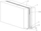
图1是本发明一种气助式双面喷雾散热的高功率刀片式服务器的结构示意图;1 is a schematic structural diagram of a high-power blade server with air-assisted double-sided spray heat dissipation according to the present invention;
图2是本发明的一种气助式双面喷雾散热的高功率刀片式服务器的纵向剖面结构示意图;2 is a schematic longitudinal cross-sectional structure diagram of a high-power blade server with air-assisted double-sided spray heat dissipation according to the present invention;
图3是本发明的气助式双面喷雾模块的结构示意图;3 is a schematic structural diagram of an air-assisted double-sided spray module of the present invention;
图4是本发明的储气板的结构示意图;Fig. 4 is the structural representation of the gas storage plate of the present invention;
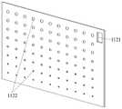
图5是本发明的进气板的结构示意图;Fig. 5 is the structural representation of the air inlet plate of the present invention;
图6是本发明的喷雾板的结构示意图;Fig. 6 is the structural representation of the spray plate of the present invention;
图7是本发明的刀片式服务器组件的结构示意图。FIG. 7 is a schematic structural diagram of the blade server assembly of the present invention.
具体实施方式Detailed ways
下面结合实施例及附图,对本发明作进一步地详细说明,但本发明的实施方式不限于此。The present invention will be described in further detail below with reference to the embodiments and the accompanying drawings, but the embodiments of the present invention are not limited thereto.
实施例Example
如图1及图2所示,一种气助式双面喷雾散热的高功率刀片式服务器,该服务器为对称结构,包括气助式双面喷雾模块1、刀片式服务器模块2、进气管道3、进液管道4以及出口管道5;As shown in Figures 1 and 2, a high-power blade server with air-assisted double-sided spray heat dissipation, the server has a symmetrical structure, including an air-assisted double-sided
所述进气管道3、进液管道4及出口管道5相互平行,可根据安装需求设置在气助式双面喷雾散热的高功率刀片式服务器的同侧或不同侧。The
所述刀片式服务器模块2包括结构相同且镜像对称设置的刀片式服务器组件21和刀片式服务器组件22。The
如图7所示,所述刀片式服务器组件21包括服务器箱体211、喷雾腔212、服务器主板213以及设置在服务器主板213上的电子元器件,如硬盘、内存条、CPU、扩展插槽及主板芯片等,所述服务器箱体为刀片式服务器各电子远器件提供安装场所。As shown in FIG. 7 , the
所述飞刀片式服务器组件22与刀片式服务器组件21结构相等,包括服务器箱体221、喷雾腔222、服务器主板223以及设置在服务器主板223上的电子元器件。The flying
所述出水口与出口管道5连接。The water outlet is connected with the outlet pipe 5 .
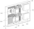
如图2及图3所示,所述气助式双面喷雾模块包括两个呈左右镜像对称,且结构相同的喷雾组件11、喷雾组件12。两个喷雾组件共用储气板。As shown in FIG. 2 and FIG. 3 , the air-assisted double-sided spray module includes two
所述气助式双面喷雾模块1包括从左至右依次叠加放置的喷雾板113、进气板112、储气板111、进气板122、喷雾板123,所述进气板112和进气板122结构相同,为镜像对称分布,所述喷雾板113和喷雾板123结构相同,为镜像对称分布;所述储气板111、进气板112及喷雾板113构成喷雾组件11;所述储气板111、进气板122及喷雾板123构成喷雾组件21。The air-assisted double-
如图4所示,所述储气板111上设有用于引出接线的服务器外接接口区1111、气体腔1112,所述气体腔1112为空腔,即气体腔1112深度等于储气板111的深度,用以容纳高压不凝性气体介质;所述气体腔1112与进气管道3相连通;As shown in FIG. 4 , the
如图5所示,所述进气板112上设有用于引出接线的服务器外接接口区1121、阵列进气孔1122,所述阵列进气孔1122呈锥形,其截面积沿气体在孔内的流动方向逐渐减小,是高压不凝性气体介质进入下一层喷雾板113流体腔1133的通道;所述阵列进气孔1122沿放置水平方向孔径大小相同,沿重力方向的孔径呈阶梯递减以实现高压气体从阵列进气孔1122末端均匀喷出。As shown in FIG. 5 , the
如图6所示,所述喷雾板113上设有用于引出接线的服务器外接接口区1131、分流腔1132、流体腔1133、阵列喷雾孔1134;所述分流腔1132与进液管道4相连通;所述分流腔1132与流体腔1133无边界连通,是用来提供液体冷却介质暂存与分配的场所;所述流体腔1133、阵列喷雾孔1134为气液冷却介质混合提供空间;所述阵列喷雾孔1134呈圆形漏斗状,即阵列喷雾孔1134的截面积沿孔内流体的速度方向先减小后增大;所述阵列喷雾孔1134沿放置水平方向孔径大小相同,沿重力方向的孔径呈阶梯递减,以实现气液混合介质从阵列喷雾孔1134均匀喷出,确保喷雾效果;如图2所示,所述阵列喷雾孔1134与阵列进气孔1122数量相等,且位置一一对应,阵列喷雾孔1134初始端面的截面积小于阵列进气孔1122末端的截面积。As shown in FIG. 6 , the
所述进气板112、喷雾板113为喷雾冷却的提前雾化提供条件。高压不凝性气体介质从阵列进气孔1122进入后,随着阵列进气孔1122截面积的减小,气体速度增加,根据伯努利方程,气体压强逐渐减小,在阵列进气孔1122的末端形成低压区。此时,液体冷却介质通过进液管道4、经由分流腔1132被吸入流体腔1133中与高压气体进行混合后进入阵列喷雾孔1134中,由于圆形漏斗状阵列喷雾孔1134的截面积沿流体流动方向先减小后增大,且初始端面截面积比阵列进气孔1122末端截面积小,进入阵列喷雾孔1134后的气体的流速继续增加,在阵列喷雾孔1134的截面积最小处,气体速度达到最大,压强最小,在阵列喷雾孔1134中形成低压区,此时,液体冷却介质以极快的速度被吸入阵列喷雾孔1134中;随后阵列喷雾孔1134的截面积逐渐增大,气体流速逐渐减小,压强逐渐增大,在高压的作用下,液体冷却介质破碎成细小的液滴群并快速从阵列喷雾孔1134的末端喷出;The
所述喷雾腔为细小液滴实现雾化提供空间。经过阵列喷雾孔喷射出来的细小液珠群,遇到喷雾腔内静止或低速的气流,在液体表面张力、粘性、空气阻力的相互作用下,逐渐由滴落、平滑流、波状流转变为雾状微细群并冲击至服务器箱体内的各电子元器件发热面上,包括服务器主板以及设置在服务器主板上的电子元器件,如硬盘、内存条、CPU、扩展插槽及主板芯片等的发热面。The spray chamber provides space for the atomization of the fine droplets. The tiny liquid droplets sprayed out through the array of spray holes meet the static or low-speed airflow in the spray chamber, and gradually change from dripping, smooth flow, and wavy flow to mist under the interaction of liquid surface tension, viscosity, and air resistance. The heat-generating surface of each electronic component in the server box, including the server motherboard and the electronic components arranged on the server motherboard, such as hard disks, memory sticks, CPUs, expansion slots and motherboard chips, etc. .
所述服务器箱体211设置出水口214与出口管道5连通;所述服务器箱体221设置出水口224与出口管道5连通,换热后的气液混合介质由出口管道5排出。The
所述喷气板112、122上截面积沿气流方向逐渐减小的阵列进气孔1122、1222以及喷雾板113、123上截面积沿流体流动方向先减小后增大的呈圆形漏斗状喷雾孔1134、1234可采用顺排或错排的分布式布局,阵列进气孔为锥形。The air inlet holes 1122 and 1222 of the
所述气体介质为空气、氮气等不凝性气体;The gas medium is non-condensable gas such as air and nitrogen;
所述液体冷却介质为绝缘导热的液体介质(如氟化液、矿物油等)。The liquid cooling medium is an insulating and heat-conducting liquid medium (such as fluorinated liquid, mineral oil, etc.).
本实施例的控制方法为:The control method of this embodiment is:
高压不凝性气体介质连续不断从进气管道进入左右两侧呈镜像对称分布的气助式双面喷雾模块从而冷却刀片式服务器箱体中设置的发热元器件,即从进气管道3通入储气腔112的高压气体,分别垂直进入锥形阵列进气孔1122、1222,随着阵列进气孔1122、1222的截面沿气体流动方向逐渐减小,气体的速度逐渐加快,气体压强逐渐减小,在阵列进气孔1122、1222的末端形成低压区,此时,液体冷却介质经由进液管道4通入与之相连通的分流腔132、152和液体腔133、153内,与高压气体进行混合后进入圆形漏斗状(截面积沿流体流动方向先减小后增大)的阵列喷雾孔1134、1234中,在其截面积最小处,气体速度达到最大,压强最小,液体冷却介质进一步被吸入阵列喷雾孔1134、1234中,在高压的作用下,破碎成细小的液滴群后从阵列喷雾孔1134、1234的末端迅速喷出,遇到喷雾腔212、222内静止或低速的气流,在液体表面张力、粘性、空气阻力的相互作用下,逐渐由滴落、平滑流、波状流转变为雾状微细群并冲击至喷雾腔212、222内的各电子元器件发热面上,包括服务器主板213、223及设置在服务器主板213、223上的元器件,如硬盘2131、内存条2132、CPU2133、扩展插槽2134及主板芯片2135等的发热面,依靠喷雾冲击、液滴相变带走电子元器件的大量热量,此时,雾状微细液滴群受热汽化并上升,在上升过程中遇到连续不断喷入的低温液体冷却介质后凝结成液态并下落至发热电子元器件的表面,继续参与换热,换热后的气液两相工质由出口管道5排出。至此,气助式双面喷雾散热模块完成一个对高功率刀片式服务器的散热过程,依此循环。The high-pressure non-condensable gas medium continuously enters the air-assisted double-sided spray module that is mirror-symmetrically distributed on the left and right sides from the intake duct to cool the heating components set in the blade server box, that is, through the
上述实施例为本发明较佳的实施方式,但本发明的实施方式并不受所述实施例的限制,其他的任何未背离本发明的精神实质与原理下所作的改变、修饰、替代、组合、简化,均应为等效的置换方式,都包含在本发明的保护范围之内。The above-mentioned embodiments are preferred embodiments of the present invention, but the embodiments of the present invention are not limited by the described embodiments, and any other changes, modifications, substitutions, and combinations made without departing from the spirit and principle of the present invention , simplification, all should be equivalent replacement modes, and are all included in the protection scope of the present invention.
Claims (4)
Priority Applications (1)
| Application Number | Priority Date | Filing Date | Title |
|---|---|---|---|
| CN202210093379.XACN114554791B (en) | 2022-01-26 | 2022-01-26 | High-power blade server with air-assisted double-sided spray heat dissipation and control method |
Applications Claiming Priority (1)
| Application Number | Priority Date | Filing Date | Title |
|---|---|---|---|
| CN202210093379.XACN114554791B (en) | 2022-01-26 | 2022-01-26 | High-power blade server with air-assisted double-sided spray heat dissipation and control method |
Publications (2)
| Publication Number | Publication Date |
|---|---|
| CN114554791A CN114554791A (en) | 2022-05-27 |
| CN114554791Btrue CN114554791B (en) | 2022-10-25 |
Family
ID=81674535
Family Applications (1)
| Application Number | Title | Priority Date | Filing Date |
|---|---|---|---|
| CN202210093379.XAActiveCN114554791B (en) | 2022-01-26 | 2022-01-26 | High-power blade server with air-assisted double-sided spray heat dissipation and control method |
Country Status (1)
| Country | Link |
|---|---|
| CN (1) | CN114554791B (en) |
Families Citing this family (1)
| Publication number | Priority date | Publication date | Assignee | Title |
|---|---|---|---|---|
| CN115426842B (en)* | 2022-08-31 | 2025-08-01 | 华南理工大学 | High-power blade server for parallel flow enhanced gas atomization cooling |
Citations (7)
| Publication number | Priority date | Publication date | Assignee | Title |
|---|---|---|---|---|
| CN107223004A (en)* | 2017-06-09 | 2017-09-29 | 苏州科技大学 | A kind of device and method of microchannel surface formula misting cooling augmentation of heat transfer |
| CN109874283A (en)* | 2019-04-18 | 2019-06-11 | 京东方科技集团股份有限公司 | Heat sink and display device |
| CN110381700A (en)* | 2019-06-25 | 2019-10-25 | 南京理工大学 | A kind of chamber and vapor chamber integral type phase-change cooling device and system by spraying |
| CN110557924A (en)* | 2018-06-03 | 2019-12-10 | 武汉麦丘科技有限公司 | Cold plate and refrigerating system with same |
| CN111642103A (en)* | 2020-04-29 | 2020-09-08 | 西南电子技术研究所(中国电子科技集团公司第十研究所) | High heat flow density porous heat sink flow cooling device |
| CN211788983U (en)* | 2020-04-29 | 2020-10-27 | 华南理工大学 | Integrated micro-injection soaking plate radiator |
| CN214751758U (en)* | 2020-12-25 | 2021-11-16 | 南京艾科美热能科技有限公司 | Atomizing phase change cooling system |
Family Cites Families (1)
| Publication number | Priority date | Publication date | Assignee | Title |
|---|---|---|---|---|
| US7255153B2 (en)* | 2005-05-25 | 2007-08-14 | International Business Machines Corporation | High performance integrated MLC cooling device for high power density ICS and method for manufacturing |
- 2022
- 2022-01-26CNCN202210093379.XApatent/CN114554791B/enactiveActive
Patent Citations (7)
| Publication number | Priority date | Publication date | Assignee | Title |
|---|---|---|---|---|
| CN107223004A (en)* | 2017-06-09 | 2017-09-29 | 苏州科技大学 | A kind of device and method of microchannel surface formula misting cooling augmentation of heat transfer |
| CN110557924A (en)* | 2018-06-03 | 2019-12-10 | 武汉麦丘科技有限公司 | Cold plate and refrigerating system with same |
| CN109874283A (en)* | 2019-04-18 | 2019-06-11 | 京东方科技集团股份有限公司 | Heat sink and display device |
| CN110381700A (en)* | 2019-06-25 | 2019-10-25 | 南京理工大学 | A kind of chamber and vapor chamber integral type phase-change cooling device and system by spraying |
| CN111642103A (en)* | 2020-04-29 | 2020-09-08 | 西南电子技术研究所(中国电子科技集团公司第十研究所) | High heat flow density porous heat sink flow cooling device |
| CN211788983U (en)* | 2020-04-29 | 2020-10-27 | 华南理工大学 | Integrated micro-injection soaking plate radiator |
| CN214751758U (en)* | 2020-12-25 | 2021-11-16 | 南京艾科美热能科技有限公司 | Atomizing phase change cooling system |
Also Published As
| Publication number | Publication date |
|---|---|
| CN114554791A (en) | 2022-05-27 |
Similar Documents
| Publication | Publication Date | Title |
|---|---|---|
| TWI693013B (en) | Spray type liquid cooling server | |
| CN109637987B (en) | Immersed jet micro-jet direct liquid cooling heat dissipation device | |
| CN105658037B (en) | A kind of cold cooling cabinet of integrated liquid | |
| US7522417B2 (en) | Multi-mode fluid cooling system and method | |
| JP2995590B2 (en) | Semiconductor cooling device | |
| US6955062B2 (en) | Spray cooling system for transverse thin-film evaporative spray cooling | |
| US7255153B2 (en) | High performance integrated MLC cooling device for high power density ICS and method for manufacturing | |
| CN111511164A (en) | Spray cooling phase change heat sink integrated evaporative cooling device | |
| JPWO2002046677A1 (en) | Cooling system and heat sink | |
| CN207780709U (en) | A kind of fountain liquid cooling server | |
| CN100461995C (en) | Array Jet Micro Heat Exchanger | |
| CN106332531B (en) | A kind of working medium cooling system by contact of server | |
| WO2018072369A1 (en) | Liquid distribution system for direct-contact type cooling cabinet | |
| CN113543588B (en) | Jet flow-transverse flow combined immersed heat dissipation device and method | |
| CN105025691A (en) | Electronic device and heat radiation device utilizing liquid cooling heat radiation and cooling method thereof | |
| CN106785822A (en) | A kind of system and method for cooling down superelevation heat flow density thermal source | |
| EP3457829B1 (en) | Cooling system of working medium contact type for heat dissipation of computer and data centre | |
| CN114599201B (en) | Micro-spray phase change liquid cooling soaking plate for server, cooling operation system and control method | |
| CN110381700B (en) | A spray cavity and steam cavity integrated phase change cooling device and system | |
| CN115175538B (en) | Data center spray phase-change liquid cooling system and data center system dynamic control method | |
| CN114554791B (en) | High-power blade server with air-assisted double-sided spray heat dissipation and control method | |
| CN114501945B (en) | Spraying liquid cooling phase change module for server, control method and manufacturing method thereof | |
| CN117476573A (en) | A manifold-microchannel cold plate for power chip heat dissipation and heat dissipation method | |
| CN115407849A (en) | Heat dissipation system, electronic equipment and liquid cooling system | |
| CN215264679U (en) | A radiator with a composite structure of a flat heat pipe and a cooling liquid plate |
Legal Events
| Date | Code | Title | Description |
|---|---|---|---|
| PB01 | Publication | ||
| PB01 | Publication | ||
| SE01 | Entry into force of request for substantive examination | ||
| SE01 | Entry into force of request for substantive examination | ||
| GR01 | Patent grant | ||
| GR01 | Patent grant |