CN114554371A - Acoustic switch and in-ear speaker - Google Patents
Acoustic switch and in-ear speakerDownload PDFInfo
- Publication number
- CN114554371A CN114554371ACN202210201385.2ACN202210201385ACN114554371ACN 114554371 ACN114554371 ACN 114554371ACN 202210201385 ACN202210201385 ACN 202210201385ACN 114554371 ACN114554371 ACN 114554371A
- Authority
- CN
- China
- Prior art keywords
- magnet
- valve core
- hole
- valve
- housing
- Prior art date
- Legal status (The legal status is an assumption and is not a legal conclusion. Google has not performed a legal analysis and makes no representation as to the accuracy of the status listed.)
- Pending
Links
Images


Classifications
- H—ELECTRICITY
- H04—ELECTRIC COMMUNICATION TECHNIQUE
- H04R—LOUDSPEAKERS, MICROPHONES, GRAMOPHONE PICK-UPS OR LIKE ACOUSTIC ELECTROMECHANICAL TRANSDUCERS; DEAF-AID SETS; PUBLIC ADDRESS SYSTEMS
- H04R1/00—Details of transducers, loudspeakers or microphones
- H04R1/10—Earpieces; Attachments therefor ; Earphones; Monophonic headphones
- H04R1/1016—Earpieces of the intra-aural type
- H—ELECTRICITY
- H04—ELECTRIC COMMUNICATION TECHNIQUE
- H04R—LOUDSPEAKERS, MICROPHONES, GRAMOPHONE PICK-UPS OR LIKE ACOUSTIC ELECTROMECHANICAL TRANSDUCERS; DEAF-AID SETS; PUBLIC ADDRESS SYSTEMS
- H04R1/00—Details of transducers, loudspeakers or microphones
- H04R1/10—Earpieces; Attachments therefor ; Earphones; Monophonic headphones
- H04R1/1041—Mechanical or electronic switches, or control elements
- H—ELECTRICITY
- H04—ELECTRIC COMMUNICATION TECHNIQUE
- H04R—LOUDSPEAKERS, MICROPHONES, GRAMOPHONE PICK-UPS OR LIKE ACOUSTIC ELECTROMECHANICAL TRANSDUCERS; DEAF-AID SETS; PUBLIC ADDRESS SYSTEMS
- H04R25/00—Deaf-aid sets, i.e. electro-acoustic or electro-mechanical hearing aids; Electric tinnitus maskers providing an auditory perception
- H04R25/60—Mounting or interconnection of hearing aid parts, e.g. inside tips, housings or to ossicles
- H04R25/603—Mounting or interconnection of hearing aid parts, e.g. inside tips, housings or to ossicles of mechanical or electronic switches or control elements
- H—ELECTRICITY
- H04—ELECTRIC COMMUNICATION TECHNIQUE
- H04R—LOUDSPEAKERS, MICROPHONES, GRAMOPHONE PICK-UPS OR LIKE ACOUSTIC ELECTROMECHANICAL TRANSDUCERS; DEAF-AID SETS; PUBLIC ADDRESS SYSTEMS
- H04R9/00—Transducers of moving-coil, moving-strip, or moving-wire type
- H04R9/02—Details
- H04R9/025—Magnetic circuit
- H—ELECTRICITY
- H04—ELECTRIC COMMUNICATION TECHNIQUE
- H04R—LOUDSPEAKERS, MICROPHONES, GRAMOPHONE PICK-UPS OR LIKE ACOUSTIC ELECTROMECHANICAL TRANSDUCERS; DEAF-AID SETS; PUBLIC ADDRESS SYSTEMS
- H04R9/00—Transducers of moving-coil, moving-strip, or moving-wire type
- H04R9/06—Loudspeakers
Landscapes
- Physics & Mathematics (AREA)
- Engineering & Computer Science (AREA)
- Acoustics & Sound (AREA)
- Signal Processing (AREA)
- Health & Medical Sciences (AREA)
- General Health & Medical Sciences (AREA)
- Neurosurgery (AREA)
- Otolaryngology (AREA)
- Magnetically Actuated Valves (AREA)
Abstract
Translated fromChinese
Description
Translated fromChinese技术领域technical field
本发明涉及一种声学装置,尤其涉及一种声学开关及入耳式扬声器。The present invention relates to an acoustic device, in particular to an acoustic switch and an in-ear speaker.
背景技术Background technique
在使用入耳式耳机或者助听器等入耳式的扬声器时,入耳式扬声器需要塞入于人的耳道内,封闭的耳道会产生堵耳效应,在使用者说话时,会感觉自己说话的声音变大、有回声,严重的堵耳感甚至可能引起头晕,影响了入耳式扬声器的使用体验。When using in-ear speakers such as in-ear headphones or hearing aids, the in-ear speakers need to be inserted into the human ear canal, and the closed ear canal will cause an ear occlusion effect. When the user speaks, he will feel that his voice becomes louder , there is echo, and severe ear blockage may even cause dizziness, which affects the experience of using in-ear speakers.
相关技术中还存在在入耳式扬声器内设置声学开关以提高声学效果的技术,入耳式扬声器设有连通耳道和外界的通道,声学开关设置在通道内,其能够在需要的时候打开或者关闭通道,在通道打开时,能够连通耳道和外界,消除堵耳效应,在通道关闭时,能够使耳道形成封闭的空间,声学效果更好。In the related art, there is also a technology of arranging an acoustic switch in the in-ear speaker to improve the acoustic effect. The in-ear speaker is provided with a channel connecting the ear canal and the outside world, and the acoustic switch is arranged in the channel, which can open or close the channel when needed. , when the channel is opened, the ear canal and the outside world can be connected, eliminating the effect of blocking the ear, and when the channel is closed, the ear canal can be formed into a closed space, and the acoustic effect is better.
然而,相关的声学开关结构复杂,在切换时常会产生较大的噪音,有些声学开关在通道打开和关闭的状态还需要持续通电;另外,相关的声学开关通常设有弹片,弹片存在疲劳变形和断裂的风险,对声学开关的可靠性和使用寿命存在不利影响。However, the related acoustic switches are complex in structure, and often generate large noises during switching. Some acoustic switches need to be continuously energized when the channel is open or closed; in addition, the related acoustic switches are usually provided with shrapnel, which have fatigue deformation and Risk of breakage, adversely affecting the reliability and service life of the acoustic switch.
因此,有必要对现有技术予以改良以克服现有技术中的所述缺陷。Therefore, it is necessary to improve the prior art to overcome the stated drawbacks in the prior art.
发明内容SUMMARY OF THE INVENTION
本发明的目的在于提供一种声学开关和入耳式扬声器,该声学开关结构更为简单。The purpose of the present invention is to provide an acoustic switch and an in-ear speaker with a simpler structure.
为实现上述发明目的,一方面,本发明提出了一种声学开关,包括:In order to achieve the above purpose of the invention, on the one hand, the present invention provides an acoustic switch, comprising:
外壳,设有内腔以及均与所述内腔相通的第一通孔和第二通孔;a casing, which is provided with an inner cavity and a first through hole and a second through hole which are both communicated with the inner cavity;
磁体组件,与所述外壳相对固定,所述磁体组件包括相对间隔设置的第一磁体和第二磁体,所述第一磁体和所述第二磁体之间形成间隔空间,所述第一磁体和所述第二磁体异极相对设置;a magnet assembly, fixed relatively to the housing, the magnet assembly includes a first magnet and a second magnet that are relatively spaced apart, a space is formed between the first magnet and the second magnet, the first magnet and the second magnet The second magnets are oppositely arranged with opposite poles;
阀芯,活动设置于所述内腔内,所述阀芯至少部分位于所述间隔空间内;a valve core, which is movably arranged in the inner cavity, and the valve core is at least partially located in the interval space;
阀座,与所述外壳相连并隔开所述第一通孔和所述第二通孔,所述阀座设有阀孔;a valve seat, which is connected to the casing and separates the first through hole and the second through hole, and the valve seat is provided with a valve hole;
线圈,所述线圈被配置为在通电后极化所述阀芯以使所述阀芯在第一位置和第二位置之间切换;在所述第一位置时,所述阀芯封闭所述阀孔;在所述第二位置时,所述阀芯打开所述阀孔。a coil configured to polarize the spool when energized to switch the spool between a first position and a second position; in the first position, the spool closes the spool valve hole; in the second position, the valve core opens the valve hole.
进一步地,在所述第一位置时,所述阀芯与所述第一磁体和所述第二磁体的其中之一吸合并封住所述阀孔;在所述第二位置时,所述阀芯与所述第一磁体和所述第二磁体的另一吸合并打开所述阀孔。Further, in the first position, the valve core attracts and seals the valve hole with one of the first magnet and the second magnet; in the second position, the valve The valve core and the other attraction of the first magnet and the second magnet open the valve hole.
进一步地,所述的声学开关还包括设于所述内腔内的导磁件,所述线圈套设于所述导磁件外部,所述导磁件、所述外壳和所述阀芯之间形成导磁回路。Further, the acoustic switch further includes a magnetic conductive member disposed in the inner cavity, the coil is sleeved outside the magnetic conductive member, and the magnetic conductive member, the casing and the valve core are arranged between the magnetic conductive member, the casing and the valve core. A magnetic conducting circuit is formed between them.
进一步地,所述外壳包括相连的第一壳体和第二壳体,所述第一通孔和所述第二通孔分别设置于所述第一壳体和所述第二壳体上,所述阀座连接在所述第一壳体和所述第二壳体之间或者与所述外壳的内侧壁相连。Further, the outer shell includes a connected first shell and a second shell, the first through hole and the second through hole are respectively provided on the first shell and the second shell, The valve seat is connected between the first housing and the second housing or connected with the inner side wall of the housing.
进一步地,所述第一壳体包括第一端板,所述第二壳体包括与所述第一端板平行设置的第二端板,所述导磁件与所述第二端板相连,所述第一磁体与所述导磁件相连,所述第二磁体与所述第一端板相连。Further, the first casing includes a first end plate, the second casing includes a second end plate arranged in parallel with the first end plate, and the magnetic conductive member is connected to the second end plate , the first magnet is connected with the magnetic conducting member, and the second magnet is connected with the first end plate.
进一步地,所述阀芯与所述外壳内侧壁滑动连接。Further, the valve core is slidably connected to the inner side wall of the housing.
进一步地,所述阀芯的第一外周面与所述外壳内侧壁间隙配合,所述阀芯开设有通气孔和/或所述阀芯的第一外周面设有凹陷的通气槽。Further, the first outer peripheral surface of the valve core is in clearance fit with the inner side wall of the housing, the valve core is provided with a ventilation hole and/or the first outer peripheral surface of the valve core is provided with a concave ventilation groove.
进一步地,所述阀芯包括套设于所述第二磁体外周的第一导向套,所述第一导向套与所述第二磁体滑动连接;和/或,Further, the valve core includes a first guide sleeve sleeved on the outer periphery of the second magnet, and the first guide sleeve is slidably connected to the second magnet; and/or,
所述阀芯包括套设于所述第一磁体外周的第二导向套,所述第二导向套与所述第一磁体滑动连接。The valve core includes a second guide sleeve sleeved on the outer periphery of the first magnet, and the second guide sleeve is slidably connected with the first magnet.
进一步地,所述第一磁体和/或所述阀芯上设置有第一缓冲垫,所述第一缓冲垫隔开所述第一磁体和所述阀芯;Further, a first buffer pad is provided on the first magnet and/or the valve core, and the first buffer pad separates the first magnet and the valve core;
所述第二磁体和/或所述阀芯上设置有第二缓冲垫,所述第二缓冲垫隔开所述第二磁体和所述阀芯,或所述阀芯上设置有第二缓冲垫,所述第二缓冲垫同时隔开所述阀芯和第二磁体及阀座。A second buffer pad is arranged on the second magnet and/or the valve core, the second buffer pad separates the second magnet and the valve core, or a second buffer pad is arranged on the valve core The second cushion pad separates the valve core from the second magnet and the valve seat at the same time.
进一步地,通过对所述线圈施加不同方向的电压驱动所述阀芯在第一位置和第二位置之间切换;或者,Further, the spool is driven to switch between the first position and the second position by applying voltages in different directions to the coil; or,
所述声学开关包括两个线圈,两个所述线圈其中之一在通电后驱动所述阀芯从第一位置切换至第二位置,另一在通电后驱动所述阀芯从第二位置切换至第一位置。The acoustic switch includes two coils, one of the two coils drives the spool to switch from the first position to the second position after being energized, and the other drives the spool to switch from the second position after being energized to the first position.
另一方面,本发明还提出了一种入耳式扬声器,包括如上任一项所述的声学开关。On the other hand, the present invention also provides an in-ear speaker, including the acoustic switch described in any one of the above.
与现有技术相比,本发明具有如下有益效果:Compared with the prior art, the present invention has the following beneficial effects:
1.本发明的声学开关设置有阀芯、用于极化阀芯的线圈以及位于阀芯两侧的第一磁体和第二磁体,线圈通电将阀芯极化为N极或者S极,以改变第一磁体和第二磁体对阀芯的磁力,从而驱动阀芯在第一位置和第二位置之间切换。本发明的声学开关无需设置弹片,结构更为简单,不存在弹片的疲劳变形或断裂问题,工作的可靠性和使用寿命更好。1. The acoustic switch of the present invention is provided with a valve core, a coil for polarizing the valve core, and a first magnet and a second magnet located on both sides of the valve core. The magnetic force of the first magnet and the second magnet to the valve core is changed, thereby driving the valve core to switch between the first position and the second position. The acoustic switch of the present invention does not need to be provided with shrapnel, has a simpler structure, does not have the problem of fatigue deformation or fracture of the shrapnel, and has better working reliability and service life.
2.由于在第一位置和第二位置时,阀芯受到第一磁体或者第二磁体的吸引力,能够保持在第一位置和第二位置,线圈无需持续通电来保持阀芯的当前位置,能耗低,发热量更小,对状态的保持更为可靠。2. Since the valve core is attracted by the first magnet or the second magnet in the first position and the second position and can be maintained in the first position and the second position, the coil does not need to be continuously energized to maintain the current position of the valve core, Low energy consumption, less heat generation, and more reliable state maintenance.
3.作为一种改进,阀芯被设置成与外壳内侧壁滑动连接和/或与第一磁体和/或第二磁体滑动连接,阀芯在运动时能够受到外壳、第一磁体或者第二磁体的引导,其移动精度更高,切换位置的动作更为准确可靠。3. As an improvement, the valve core is arranged to be slidably connected to the inner side wall of the housing and/or to the first magnet and/or the second magnet, and the valve core can be affected by the housing, the first magnet or the second magnet when moving. It has higher movement accuracy, and the action of switching positions is more accurate and reliable.
附图说明Description of drawings
图1是本发明中一种实施方式的声学开关的结构示意图。FIG. 1 is a schematic structural diagram of an acoustic switch according to an embodiment of the present invention.
图2是图1所示的声学开关的爆炸图。FIG. 2 is an exploded view of the acoustic switch shown in FIG. 1 .
图3是图1所示的声学开关的立体剖面图。FIG. 3 is a perspective cross-sectional view of the acoustic switch shown in FIG. 1 .
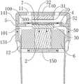
图4是图1所示的声学开关的剖视图,图中,阀芯处于第一位置,声学开关处于关闭状态。4 is a cross-sectional view of the acoustic switch shown in FIG. 1 , in which the valve core is in a first position and the acoustic switch is in a closed state.
图5是图4中的阀芯呈环状时的示意图。FIG. 5 is a schematic view of the valve core in FIG. 4 when it is annular.
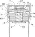
图6是图1所示的声学开关的剖视图,图中,阀芯处于第二位置,开关处于打开状态。FIG. 6 is a cross-sectional view of the acoustic switch shown in FIG. 1 , in which the valve core is in a second position and the switch is in an open state.
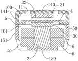
图7是本发明中一种实施方式的声学开关的剖视图,图中,阀芯设于第二腔体内,开关处于关闭状态。7 is a cross-sectional view of an acoustic switch according to an embodiment of the present invention. In the figure, the valve core is arranged in the second cavity, and the switch is in a closed state.
图8是图7所示的声学开关中阀芯处于第二位置时的示意图,开关处于打开状态。FIG. 8 is a schematic diagram of the acoustic switch shown in FIG. 7 when the valve core is in the second position, and the switch is in an open state.
图9是本发明中一种实施方式的声学开关的剖视图,图中,线圈的数量为两个。9 is a cross-sectional view of an acoustic switch according to an embodiment of the present invention, in which the number of coils is two.
图10是本发明中一种实施方式的声学开关的剖视图,图中,阀座与外壳内侧壁相连。10 is a cross-sectional view of an acoustic switch according to an embodiment of the present invention, in which the valve seat is connected to the inner side wall of the housing.
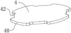
图11是本发明中一种实施方式的阀芯的结构示意图,图中,阀芯设置有通气槽。11 is a schematic structural diagram of a valve core according to an embodiment of the present invention, in the figure, the valve core is provided with a ventilation groove.
图12是本发明中一种实施方式的阀芯与外壳内侧壁配接的示意图,图中,阀芯设有通气槽。FIG. 12 is a schematic diagram of the valve core and the inner side wall of the housing according to an embodiment of the present invention. In the figure, the valve core is provided with a ventilation groove.
图13是本发明中一种实施方式的阀芯与外壳内侧壁配接的示意图,图中,阀芯设有通气孔。FIG. 13 is a schematic diagram of the valve core and the inner side wall of the housing according to an embodiment of the present invention, in which the valve core is provided with a ventilation hole.
图14是本发明中一种实施方式的阀芯与第二磁体滑动连接的示意图。FIG. 14 is a schematic diagram of sliding connection between the valve core and the second magnet according to an embodiment of the present invention.
图15是本发明中一种实施方式的阀芯与第一磁体滑动连接的示意图。FIG. 15 is a schematic diagram of sliding connection between the valve core and the first magnet according to an embodiment of the present invention.
图16是本发明中一种实施方式的阀芯上设置缓冲垫的剖视图。16 is a cross-sectional view of a cushion pad provided on a valve core according to an embodiment of the present invention.
图17是本发明中一种实施方式的入耳式扬声器位于耳道内的示意图。FIG. 17 is a schematic diagram of an in-ear speaker located in the ear canal according to an embodiment of the present invention.
具体实施方式Detailed ways
为使本申请的上述目的、特征和优点能够更为明显易懂,下面结合附图,对本申请的具体实施方式做详细的说明。可以理解的是,此处所描述的具体实施例仅用于解释本申请,而非对本申请的限定。另外还需要说明的是,为了便于描述,附图中仅示出了与本申请相关的部分而非全部结构。基于本申请中的实施例,本领域普通技术人员在没有做出创造性劳动前提下所获得的所有其它实施例,都属于本申请保护的范围。In order to make the above objects, features and advantages of the present application more clearly understood, the specific embodiments of the present application will be described in detail below with reference to the accompanying drawings. It should be understood that the specific embodiments described herein are only used to explain the present application, but not to limit the present application. In addition, it should be noted that, for the convenience of description, the drawings only show some but not all the structures related to the present application. Based on the embodiments in the present application, all other embodiments obtained by those of ordinary skill in the art without creative work fall within the protection scope of the present application.
本申请中的术语“包括”和“具有”以及它们任何变形,意图在于覆盖不排他的包含。例如包含了一系列步骤或单元的过程、方法、系统、产品或设备没有限定于已列出的步骤或单元,而是可选地还包括没有列出的步骤或单元,或可选地还包括对于这些过程、方法、产品或设备固有的其它步骤或单元。The terms "comprising" and "having" and any variations thereof in this application are intended to cover a non-exclusive inclusion. For example, a process, method, system, product or device comprising a series of steps or units is not limited to the listed steps or units, but optionally also includes unlisted steps or units, or optionally also includes For other steps or units inherent to these processes, methods, products or devices.
在本文中提及“实施例”意味着,结合实施例描述的特定特征、结构或特性可以包含在本申请的至少一个实施例中。在说明书中的各个位置出现该短语并不一定均是指相同的实施例,也不是与其它实施例互斥的独立的或备选的实施例。本领域技术人员显式地和隐式地理解的是,本文所描述的实施例可以与其它实施例相结合。Reference herein to an "embodiment" means that a particular feature, structure, or characteristic described in connection with the embodiment can be included in at least one embodiment of the present application. The appearances of the phrase in various places in the specification are not necessarily all referring to the same embodiment, nor a separate or alternative embodiment that is mutually exclusive of other embodiments. It is explicitly and implicitly understood by those skilled in the art that the embodiments described herein may be combined with other embodiments.
对应于本发明一种较佳实施例的声学开关,其包括外壳1、磁体组件3、阀芯4、阀座5和线圈6。Corresponding to an acoustic switch according to a preferred embodiment of the present invention, it includes a
如图1至图3所示,外壳1采用导磁材料制成,其设有内腔10、第一通孔11和第二通孔12,第一通孔11和第二通孔12均连通内腔10和外界,以使得第一通孔11、内腔10和第二通孔12之间形成气流通道。As shown in FIGS. 1 to 3 , the
磁体组件3与外壳1相对固定,其包括相对间隔设置的第一磁体30和第二磁体31,如图4所示,第一磁体30和第二磁体31之间形成间隔空间32,第一磁体30和第二磁体31异极相对设置,即第一磁体30和第二磁体31相对设置的磁极为N极和S极。继续参考图4,图4示出的实施例中,第一磁体30靠近第二磁体31的磁极为N极,第二磁体31靠近第一磁体30的磁极为S极;在其他实施例中,也可以将第一磁体30靠近第二磁体31的磁极设置为S极,将第二磁体31靠近第一磁体30的磁极设置为N极。The
阀芯4活动设置在内腔10内,其能够沿着内腔10的轴线方向(即阀芯4的运动轴线方向)做往复运动。阀芯4至少部分位于间隔空间32内,这样,在其被极化成N极或者S极后,能够高效地被第一磁体30和第二磁体31吸引或排斥。作为一种优选的实施方式,参考图5,阀芯4呈环状,其部分延伸至间隔空间32内。作为另一种优选的实施方式,参考图4,阀芯4呈实心的板状。The
阀座5与外壳1相连,其将内腔10分隔成第一腔体100和第二腔体101,其中,第一通孔11与第一腔体100相通,第二通孔12与第二腔体101相通。在阀座5上开设有连通第一腔体100和第二腔体101的阀孔50。这样,阀孔50即位于第一通孔11和第二通孔12之间,在阀孔50打开时,第一通孔11和第二通孔12能够通过阀孔50相通,此时气流通道被打开。而在阀孔50被阀芯4封闭时,第一通孔11和第二通孔12之间的连通被关断,此时气流通道被关断。The
阀芯4具有第一位置和第二位置,在第一位置时,其与阀座5贴紧,从而封住阀孔50,在第二位置时,其与阀座5脱离,从而打开阀孔50。阀芯4可以设置在第一腔体100或者第二腔体101内。参考图4,图4示出了阀芯4设置于第一腔体100内的一种情形,该情形中,第一磁体30伸入阀孔50内,其上端面300与阀座5的上表面52大致平齐。当阀芯4处于第一位置时,其与第一磁体30吸合,且同时与阀座5上表面52贴合从而封住阀孔50,当阀芯4处于第二位置时,参考图6,其与第二磁体31吸合,且与阀座5脱离接触,从而打开阀孔50。在阀芯4设置在第二腔体101内时,参考图7,图7示出了阀芯4设置于第二腔体101内的一种情形,该情形中,第二磁体31伸入阀孔50内,其下端面310与阀座5的下表面51大致平齐。当阀芯4处于第一位置时,其与第二磁体31吸合,且同时与阀座5下表面51贴合从而封住阀孔50。当阀芯4处于第二位置时,参考图8,其与第一磁体30吸合,且与阀座5脱离接触,从而打开阀孔50。The
线圈6用于通电产生磁场,将阀芯4至少位于间隔空间32内的部分极化为N极或者S极,以使得阀芯4能够在第一磁体30和第二磁体31的磁力的作用下在第一位置和第二位置之间进行切换。The
以阀芯4设于第一腔体100内时为例,参考图4,图4中,第一磁体30靠近第二磁体31的端部的磁极为N极,第二磁体31靠近第一磁体30的磁极为S极,阀芯4设置在第一腔体100内。图4中阀芯4处于第一位置,当阀芯4被极化成N极时,第一磁体30将对其施加斥力,第二磁体31将对其施加吸力,此时,阀芯4将向着第二磁体31移动至与第二磁体31吸合的第二位置。当需要切换至第一位置时,参考图6,只需将阀芯4极化成S极,此时,第二磁体31对其施加斥力,第一磁体30对其施加吸力,阀芯4将向着第一磁体30移动至与第一磁体30吸合的第一位置。Taking the
作为一种优选的实施方式,声学开关还包括设于内腔10内的导磁件2,线圈6为空心线圈,其套设在导磁件2外部,并与外壳1相固定,例如采用粘结剂与外壳1粘接。外壳1、导磁件2和阀芯4采用导磁材料制成,三者之间形成导磁回路。在线圈6通电后,参考图4,图4中以带箭头的虚线示意出了导磁回路,图4中,磁感线从阀芯4穿入导磁件2内,此时阀芯4被极化为N极,导磁件2被极化为S极。当线圈6通电产生图6所示的导磁回路时,磁感线从导磁件2穿入阀芯4内,此时阀芯4被极化为S极,导磁件2被极化为N极。As a preferred embodiment, the acoustic switch further includes a magnetic
可以理解的是,导磁件2可以是与外壳1相独立的零部件,两者通过焊接或者胶粘剂粘接相连,也可以是与外壳1一体成型的,即导磁件2为外壳1的一部分。It can be understood that the magnetic
在一种实施方式中,通过对同一线圈6施加不同方向的电压,改变线圈6产生的磁场的方向,从而改变阀芯4的极性。在另一种实施方式中,如图9所示,导磁件2外部设置有两个线圈6,两个线圈6在通电后产生方向不同的磁场,可以将两个线圈6的绕线方向设置成相反的形式或者将施加在两个线圈6上的电压的方向设置成相反的形式来改变两个线圈6各自产生的磁场方向,这样,通过对不同的线圈6进行通电,能够改变阀芯4的极性。例如,在一个线圈6通电后,阀芯4被极化为N极,则在该线圈6断电,另一线圈6通电后,阀芯4被极化为S极。In one embodiment, by applying voltages in different directions to the
通过对线圈6通电极化阀芯4的方式,能够改变第一磁体30和第二磁体31对阀芯4的磁力方向,进而驱动阀芯4在第一位置和第二位置之间切换,实现声学开关的通断,无需设置弹片或者其他弹性件,结构更为简单可靠,不易因为弹片的疲劳变形或断裂影响使用性能,同时,还能够降低弹片装配在外壳内的组装难度,提高生产效率。另外,线圈6只需在需要切换位置的时候通电,在位置切换完成后,由于阀芯4本身采用导磁材料制成,因此其与第一磁体30或者第二磁体31之间具有磁吸力,线圈6无需持续通电来保持阀芯4的位置,能够减少能量的消耗,降低发热量,进一步提高声学开关的使用寿命和使用可靠性。By energizing the
为便于将零部件安装至内腔10内,外壳1可以采用多个零件连接而成。在一种优选的实施方式中,参考图1至图3,外壳1包括第一壳体14和第二壳体15,第一壳体14和第二壳体15配合形成内腔10,第一通孔11和第二通孔12分别设置在第一壳体14和第二壳体15上。In order to facilitate the installation of components into the
第一壳体14包括第一端板140以及自第一端板140外缘沿着垂直于第一端板140的方向凸出的第一环壁141,第二壳体15包括第二端板150以及自第二端板150外缘沿着垂直于第二端板150的方向凸出的第二环壁151。第一端板140和第二端板150相平行设置,其中,第二磁体31连接在第一端板140上,导磁件2连接在第二端板150上,第一磁体30连接在导磁件2朝向阀芯4的端面上。The
在一些实施方式中,参考图4,阀座5连接在第一壳体14和第二壳体15之间,此时,阀座5采用导磁材料制成,以保证第一壳体14和第二壳体15之间的导磁效率。在另一些实施方式中,参考图10,阀座5的外周面与外壳1内侧壁13相连,第一壳体14和第二壳体15直接相连,此时,阀座5可以采用非导磁材料制成。In some embodiments, referring to FIG. 4 , the
为了使得阀芯4可靠的沿着其运动轴线运动,减少其在运动过程中位置的偏差,阀芯4被设置成与外壳1内侧壁13滑动连接。参考图11至图13,作为一种优选的实施方式,阀芯4的第一外周面40与外壳1内侧壁13间隙配合,以使得阀芯4能够沿着内侧壁13移动,位置更为准确。在该实施方式中,为了使得阀芯4打开时,气体流通更为顺畅,可以在阀芯4上开设贯穿其上下表面的通气孔41(参考图13),或者在阀芯4的第一外周面40上设置凹陷的通气槽42(参考图11和图12),当然也可以在阀芯4上同时设置通气孔41和通气槽42,通过设置通气孔41和通气槽42,能够增大气体的流通面积。在该实施方式中,阀芯4可以设置成板状,结构更为简单,成本更低。In order to make the
除了上述的将阀芯4设置成与外壳1内侧壁13滑动连接的形式外,还可以将阀芯4设置成与第一磁体30和/或第二磁体31滑动连接的形式。具体的,在一种实施方式中,参考图14,阀芯4包括用于在第一位置时封住阀孔50的板部43以及自板部43外凸的第一导向套44,第一导向套44采用非导磁材料制成并套设在第二磁体31外周,两者之间形成滑动连接。在位置切换过程中,通过第一导向套44和第二磁体31的导向作用提高阀芯4的移动精度。在另一种实施方式中,参考图15,阀芯4包括用于在第一位置时封住阀孔50的板部43以及自板部43外凸的第二导向套45,第二导向套45采用非导磁材料制成并套设在第一磁体30外周,两者之间形成滑动连接。在位置切换过程中,通过第二导向套45和第一磁体30的导向作用提高阀芯4的移动精度。在其他实施方式中,阀芯4包括板部43以及分别设置在板部43两侧的第一导向套44和第二导向套45,第一导向套44和第二导向套45分别套设于第二磁体31和第一磁体30上实现滑动连接。In addition to the above-mentioned form in which the
为了降低在阀芯4的位置切换过程中产生的噪音,同时防止阀芯4和磁体直接贴合导致吸合力太大难以脱开,声学开关还包括用于隔开第一磁体30和阀芯4的第一缓冲垫7以及用于隔开第二磁体30和阀芯4的第二缓冲垫70。第一缓冲垫7和第二缓冲垫70采用非导磁材料制成,且其为软性材料,例如是塑料、橡胶、海绵等,在隔开阀芯4和磁体的同时能够起到缓冲、吸收振动和降低噪音的作用。In order to reduce the noise generated during the position switching process of the
例如,参考图3和图4,在第一磁体30朝向阀芯4的表面上设置有第一缓冲垫7,以在第一位置时,第一磁体30与阀芯4之间通过第一缓冲垫7隔开,这样,在阀芯4由第二位置切换到第一位置时,第一缓冲垫7能够起到缓冲的作用,同时也能够起到减振降噪的作用,防止因为撞击损坏相应的零部件,第一缓冲垫7上表面高于阀座5的上表面52,阀芯4在压缩第一缓冲垫7后与阀座5贴合,能够在起到缓冲作用的同时,保证阀芯4对阀孔50的密封效果。当然,还可以在阀芯4朝向第一磁体30的表面上设置第一缓冲垫7和/或在阀座5朝向阀芯4的表面上设置第一缓冲垫7,参考图16,在阀芯4朝向第一磁体30的表面上设置第一缓冲垫7,在第一位置时,第一缓冲垫7能够同时与阀座5和第一磁体30接触,把阀芯4和第一磁体30及阀座5同时隔开,拥有更好的密封效果。For example, referring to FIGS. 3 and 4 , a
类似的,参考图3和图6,在第二磁体31朝向阀芯4的表面上设置有第二缓冲垫70,以在第二位置时,第二磁体31与阀芯4之间通过第二缓冲垫70隔开,这样,在阀芯4由第一位置切换到第二位置时,第二缓冲垫70能够起到减振降噪以及缓冲的作用。当然,还可以在阀芯4朝向第二磁体31的表面上设置第二缓冲垫70,或者同时在第二磁体31朝向阀芯4的表面上和阀芯4朝向第二磁体31的表面上设置第二缓冲垫70。Similarly, referring to FIG. 3 and FIG. 6 , a
本发明还提出一种入耳式扬声器,如图17所示,其包括壳体8以及设置在其壳体8内的声学开关90。在使用时,入耳式扬声器设于耳道9内,壳体8包括朝向耳道9内部的第一端和朝向外界的第二端,壳体8设有连通第一端和第二端的通道80,声学开关90设在通道80上,通过控制声学开关90的通断可以控制通道80的通断。入耳式扬声器的控制系统能够检测人是否处于说话状态,当人处于说话状态时,控制系统控制声学开关打开,此时,耳道9内部和耳道9外部通过通道80连通,能够消除堵耳效应;当人未处于说话状态时,控制系统控制声学开关关闭,此时,耳道9内形成密闭的空间,能够更好的隔绝外部噪音,提高入耳式扬声器的声学表现效果。The present invention also provides an in-ear speaker, as shown in FIG. 17 , which includes a
上述仅为本发明的具体实施方式,其它基于本发明构思的前提下做出的任何改进都视为本发明的保护范围。The above are only specific embodiments of the present invention, and any improvements made based on the concept of the present invention are regarded as the protection scope of the present invention.
Claims (11)
Translated fromChinesePriority Applications (1)
| Application Number | Priority Date | Filing Date | Title |
|---|---|---|---|
| CN202210201385.2ACN114554371A (en) | 2022-03-03 | 2022-03-03 | Acoustic switch and in-ear speaker |
Applications Claiming Priority (1)
| Application Number | Priority Date | Filing Date | Title |
|---|---|---|---|
| CN202210201385.2ACN114554371A (en) | 2022-03-03 | 2022-03-03 | Acoustic switch and in-ear speaker |
Publications (1)
| Publication Number | Publication Date |
|---|---|
| CN114554371Atrue CN114554371A (en) | 2022-05-27 |
Family
ID=81662201
Family Applications (1)
| Application Number | Title | Priority Date | Filing Date |
|---|---|---|---|
| CN202210201385.2APendingCN114554371A (en) | 2022-03-03 | 2022-03-03 | Acoustic switch and in-ear speaker |
Country Status (1)
| Country | Link |
|---|---|
| CN (1) | CN114554371A (en) |
Cited By (1)
| Publication number | Priority date | Publication date | Assignee | Title |
|---|---|---|---|---|
| CN118400659A (en)* | 2024-07-01 | 2024-07-26 | 共达电声股份有限公司 | Air switch and earphone |
Citations (6)
| Publication number | Priority date | Publication date | Assignee | Title |
|---|---|---|---|---|
| CN107278377A (en)* | 2015-02-27 | 2017-10-20 | 苹果公司 | Valve based on balanced armature |
| US20190320272A1 (en)* | 2018-04-12 | 2019-10-17 | Knowles Electronics, Llc | Acoustic valve for hearing device |
| CN111327983A (en)* | 2018-12-14 | 2020-06-23 | 大北欧听力公司 | Earphone for determining the state of a closure element for ventilation |
| US20200213786A1 (en)* | 2018-12-31 | 2020-07-02 | Knowles Electronics, Llc | Acoustic valve for hearing device |
| CN114040294A (en)* | 2021-11-30 | 2022-02-11 | 中科声特美(苏州)声学科技有限公司 | Acoustic switch and in-ear speaker |
| CN217428347U (en)* | 2022-03-03 | 2022-09-13 | 中科声特美(苏州)声学科技有限公司 | Acoustic switch and in-ear speaker |
- 2022
- 2022-03-03CNCN202210201385.2Apatent/CN114554371A/enactivePending
Patent Citations (6)
| Publication number | Priority date | Publication date | Assignee | Title |
|---|---|---|---|---|
| CN107278377A (en)* | 2015-02-27 | 2017-10-20 | 苹果公司 | Valve based on balanced armature |
| US20190320272A1 (en)* | 2018-04-12 | 2019-10-17 | Knowles Electronics, Llc | Acoustic valve for hearing device |
| CN111327983A (en)* | 2018-12-14 | 2020-06-23 | 大北欧听力公司 | Earphone for determining the state of a closure element for ventilation |
| US20200213786A1 (en)* | 2018-12-31 | 2020-07-02 | Knowles Electronics, Llc | Acoustic valve for hearing device |
| CN114040294A (en)* | 2021-11-30 | 2022-02-11 | 中科声特美(苏州)声学科技有限公司 | Acoustic switch and in-ear speaker |
| CN217428347U (en)* | 2022-03-03 | 2022-09-13 | 中科声特美(苏州)声学科技有限公司 | Acoustic switch and in-ear speaker |
Non-Patent Citations (3)
| Title |
|---|
| 凌立新: "化工单元实训操作", 30 November 2020, 重庆大学出版社, pages: 283 - 284* |
| 王亚军: "运载火箭增压输送系统", 31 December 2020, 中国宇航出版社, pages: 355 - 358* |
| 黄日新: "工业专用阀门选用手册", 30 April 1998, 机械工业出版社, pages: 11* |
Cited By (1)
| Publication number | Priority date | Publication date | Assignee | Title |
|---|---|---|---|---|
| CN118400659A (en)* | 2024-07-01 | 2024-07-26 | 共达电声股份有限公司 | Air switch and earphone |
Similar Documents
| Publication | Publication Date | Title |
|---|---|---|
| EP2345259B1 (en) | Acoustic valve mechanisms | |
| CN111357300B (en) | AC installations including acoustic seals and drain openings | |
| CN106231512B (en) | Sound pipeline, loudspeaker assembly and two-side sound-emitting mobile phone | |
| US6751326B2 (en) | Vibration-dampening receiver assembly | |
| CN114025277A (en) | Acoustic valve and in-ear speaker | |
| CN214960093U (en) | Acoustic device with deformable shape as valve | |
| JPWO2005086522A1 (en) | Bone conduction device | |
| CN114554371A (en) | Acoustic switch and in-ear speaker | |
| CN217428347U (en) | Acoustic switch and in-ear speaker | |
| JP5033667B2 (en) | Speaker | |
| CN217428346U (en) | Acoustic switch and in-ear speaker | |
| CN114040294B (en) | Acoustic switch and in-ear speaker | |
| CN217037416U (en) | Acoustic switch and in-ear speaker | |
| CN217037415U (en) | Acoustic valve and in-ear speaker | |
| CN112689041B (en) | Electronic equipment | |
| CN216721538U (en) | Acoustic switch and sound production device | |
| CN217183444U (en) | Acoustic switch and sound production device | |
| CN114040295A (en) | An acoustic switch and a sound producing device | |
| CN114554370A (en) | Acoustic switch and in-ear speaker | |
| WO2023246687A1 (en) | Earphone | |
| CN217656728U (en) | Acoustic switch shell and acoustic switch | |
| CN223274101U (en) | Acoustic switch and electronic equipment | |
| CN218788821U (en) | Air valve and wearable equipment | |
| CN117676409A (en) | Acoustic pass-through switch and electronic equipment | |
| JP5855561B2 (en) | Speaker device |
Legal Events
| Date | Code | Title | Description |
|---|---|---|---|
| PB01 | Publication | ||
| PB01 | Publication | ||
| SE01 | Entry into force of request for substantive examination | ||
| SE01 | Entry into force of request for substantive examination |