CN114553079B - Voltage-adjustable switched reluctance generator power converter and control method thereof - Google Patents
Voltage-adjustable switched reluctance generator power converter and control method thereofDownload PDFInfo
- Publication number
- CN114553079B CN114553079BCN202210447758.4ACN202210447758ACN114553079BCN 114553079 BCN114553079 BCN 114553079BCN 202210447758 ACN202210447758 ACN 202210447758ACN 114553079 BCN114553079 BCN 114553079B
- Authority
- CN
- China
- Prior art keywords
- switching tube
- switched reluctance
- capacitor
- reluctance generator
- voltage
- Prior art date
- Legal status (The legal status is an assumption and is not a legal conclusion. Google has not performed a legal analysis and makes no representation as to the accuracy of the status listed.)
- Active
Links
- 238000000034methodMethods0.000titleclaimsabstractdescription32
- 239000003990capacitorSubstances0.000claimsabstractdescription123
- 230000005284excitationEffects0.000claimsabstractdescription68
- 230000005347demagnetizationEffects0.000claimsabstractdescription14
- 238000004804windingMethods0.000claimsdescription100
- 238000010248power generationMethods0.000claimsdescription20
- 230000001276controlling effectEffects0.000claims3
- 230000001105regulatory effectEffects0.000claims1
- 238000010586diagramMethods0.000description7
- 230000005611electricityEffects0.000description3
- 238000012986modificationMethods0.000description2
- 230000004048modificationEffects0.000description2
Images


Classifications
- H—ELECTRICITY
- H02—GENERATION; CONVERSION OR DISTRIBUTION OF ELECTRIC POWER
- H02P—CONTROL OR REGULATION OF ELECTRIC MOTORS, ELECTRIC GENERATORS OR DYNAMO-ELECTRIC CONVERTERS; CONTROLLING TRANSFORMERS, REACTORS OR CHOKE COILS
- H02P9/00—Arrangements for controlling electric generators for the purpose of obtaining a desired output
- H02P9/14—Arrangements for controlling electric generators for the purpose of obtaining a desired output by variation of field
- H02P9/26—Arrangements for controlling electric generators for the purpose of obtaining a desired output by variation of field using discharge tubes or semiconductor devices
- H02P9/30—Arrangements for controlling electric generators for the purpose of obtaining a desired output by variation of field using discharge tubes or semiconductor devices using semiconductor devices
- H02P9/305—Arrangements for controlling electric generators for the purpose of obtaining a desired output by variation of field using discharge tubes or semiconductor devices using semiconductor devices controlling voltage
- H—ELECTRICITY
- H02—GENERATION; CONVERSION OR DISTRIBUTION OF ELECTRIC POWER
- H02M—APPARATUS FOR CONVERSION BETWEEN AC AND AC, BETWEEN AC AND DC, OR BETWEEN DC AND DC, AND FOR USE WITH MAINS OR SIMILAR POWER SUPPLY SYSTEMS; CONVERSION OF DC OR AC INPUT POWER INTO SURGE OUTPUT POWER; CONTROL OR REGULATION THEREOF
- H02M3/00—Conversion of DC power input into DC power output
- H02M3/02—Conversion of DC power input into DC power output without intermediate conversion into AC
- H02M3/04—Conversion of DC power input into DC power output without intermediate conversion into AC by static converters
- H02M3/06—Conversion of DC power input into DC power output without intermediate conversion into AC by static converters using resistors or capacitors, e.g. potential divider
- H02M3/07—Conversion of DC power input into DC power output without intermediate conversion into AC by static converters using resistors or capacitors, e.g. potential divider using capacitors charged and discharged alternately by semiconductor devices with control electrode, e.g. charge pumps
- H—ELECTRICITY
- H02—GENERATION; CONVERSION OR DISTRIBUTION OF ELECTRIC POWER
- H02P—CONTROL OR REGULATION OF ELECTRIC MOTORS, ELECTRIC GENERATORS OR DYNAMO-ELECTRIC CONVERTERS; CONTROLLING TRANSFORMERS, REACTORS OR CHOKE COILS
- H02P9/00—Arrangements for controlling electric generators for the purpose of obtaining a desired output
- H02P9/006—Means for protecting the generator by using control
- H—ELECTRICITY
- H02—GENERATION; CONVERSION OR DISTRIBUTION OF ELECTRIC POWER
- H02P—CONTROL OR REGULATION OF ELECTRIC MOTORS, ELECTRIC GENERATORS OR DYNAMO-ELECTRIC CONVERTERS; CONTROLLING TRANSFORMERS, REACTORS OR CHOKE COILS
- H02P9/00—Arrangements for controlling electric generators for the purpose of obtaining a desired output
- H02P9/10—Control effected upon generator excitation circuit to reduce harmful effects of overloads or transients, e.g. sudden application of load, sudden removal of load, sudden change of load
- H02P9/12—Control effected upon generator excitation circuit to reduce harmful effects of overloads or transients, e.g. sudden application of load, sudden removal of load, sudden change of load for demagnetising; for reducing effects of remanence; for preventing pole reversal
- H02P9/123—Control effected upon generator excitation circuit to reduce harmful effects of overloads or transients, e.g. sudden application of load, sudden removal of load, sudden change of load for demagnetising; for reducing effects of remanence; for preventing pole reversal for demagnetising; for reducing effects of remanence
Landscapes
- Engineering & Computer Science (AREA)
- Power Engineering (AREA)
- Control Of Eletrric Generators (AREA)
Abstract
Translated fromChinese
Description
Translated fromChinese技术领域technical field
本发明涉及开关磁阻发电机驱动系统,具体是一种电压可调式开关磁阻发电机功率变换器及其控制方法。The invention relates to a switched reluctance generator drive system, in particular to a voltage-adjustable switched reluctance generator power converter and a control method thereof.
背景技术Background technique
开关磁阻发电机作为一种无永磁体的特种电机,由于设计简单、造价低廉、方便实现电动/发电状态灵活切换等众多优势,在电动汽车、船舶、航空航天等领域中都有很好的应用前景。而功率变换器作为开关磁阻发电机驱动系统能量交换的重要场所,在提高输出能力、优化系统性能和能量管理方面起很大作用。As a special motor without permanent magnets, the switched reluctance generator has many advantages such as simple design, low cost, and convenient and flexible switching of electric/generating states. application prospects. The power converter, as an important place for the energy exchange of the switched reluctance generator drive system, plays a great role in improving the output capacity, optimizing the system performance and energy management.
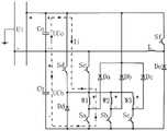
在现有技术条件下,功率变换器普遍采用不对称半桥电路(如图1所示)。但在实际应用中,此种电路由于自身原理所限,无法灵活调节开关磁阻发电机的励磁电压和去磁电压,由此导致开关磁阻发电机的输出功率范围小、高低速性能差、发电效率低。基于此,有必要发明一种电压可调式开关磁阻发电机功率变换器及其控制方法,以解决现有功率变换器无法灵活调节开关磁阻发电机的励磁电压和去磁电压的问题。Under the existing technical conditions, power converters generally use asymmetric half-bridge circuits (as shown in Figure 1). However, in practical applications, this kind of circuit cannot flexibly adjust the excitation voltage and demagnetization voltage of the switched reluctance generator due to its own principle, resulting in a small output power range of the switched reluctance generator, poor high and low speed performance, Low power generation efficiency. Based on this, it is necessary to invent a voltage-adjustable switched reluctance generator power converter and a control method thereof to solve the problem that the existing power converter cannot flexibly adjust the excitation voltage and demagnetization voltage of the switched reluctance generator.
发明内容SUMMARY OF THE INVENTION
本发明为了解决现有功率变换器无法灵活调节开关磁阻发电机的励磁电压和去磁电压的问题,提供了一种电压可调式开关磁阻发电机功率变换器及其控制方法。In order to solve the problem that the existing power converter cannot flexibly adjust the excitation voltage and demagnetization voltage of the switched reluctance generator, the present invention provides a voltage-adjustable switched reluctance generator power converter and a control method thereof.
本发明是采用如下技术方案实现的:The present invention adopts following technical scheme to realize:
一种电压可调式开关磁阻发电机功率变换器,包括第一电容、第二电容、第一开关管、第二开关管、第三开关管、第四开关管、第五开关管、第一续流二极管、第二续流二极管、第三续流二极管、第四续流二极管、Buck-Boost变换器;A voltage-adjustable switched reluctance generator power converter, comprising a first capacitor, a second capacitor, a first switch, a second switch, a third switch, a fourth switch, a fifth switch, a first switch Freewheeling diode, second freewheeling diode, third freewheeling diode, fourth freewheeling diode, Buck-Boost converter;
所述Buck-Boost变换器包括第六开关管、第五续流二极管、电感;The Buck-Boost converter includes a sixth switch tube, a fifth freewheeling diode, and an inductor;
其中,第一电容的正端与正电源端连接;第一电容的负端与负电源端连接;第二电容的正端与负电源端连接;The positive terminal of the first capacitor is connected to the positive power terminal; the negative terminal of the first capacitor is connected to the negative power terminal; the positive terminal of the second capacitor is connected to the negative power terminal;
第一开关管的集电极与开关磁阻发电机的第一相绕组的负端连接;第二开关管的集电极与开关磁阻发电机的第二相绕组的负端连接;第三开关管的集电极与开关磁阻发电机的第三相绕组的负端连接;第一开关管的发射极、第二开关管的发射极、第三开关管的发射极均与第二电容的负端连接;The collector of the first switch tube is connected to the negative end of the first phase winding of the switched reluctance generator; the collector of the second switch tube is connected to the negative end of the second phase winding of the switched reluctance generator; the third switch tube The collector of the switch is connected to the negative end of the third phase winding of the switched reluctance generator; the emitter of the first switch tube, the emitter of the second switch tube, and the emitter of the third switch tube are all connected to the negative end of the second capacitor connect;
第一续流二极管的阳极与开关磁阻发电机的第一相绕组的负端连接;第二续流二极管的阳极与开关磁阻发电机的第二相绕组的负端连接;第三续流二极管的阳极与开关磁阻发电机的第三相绕组的负端连接;第一续流二极管的阴极、第二续流二极管的阴极、第三续流二极管的阴极均与正电源端连接;The anode of the first freewheeling diode is connected to the negative terminal of the first phase winding of the switched reluctance generator; the anode of the second freewheeling diode is connected to the negative terminal of the second phase winding of the switched reluctance generator; the third freewheeling diode The anode of the diode is connected to the negative terminal of the third phase winding of the switched reluctance generator; the cathode of the first freewheeling diode, the cathode of the second freewheeling diode, and the cathode of the third freewheeling diode are all connected to the positive power supply terminal;
第四开关管的集电极与正电源端连接;第四开关管的发射极分别与开关磁阻发电机的第一相绕组的正端、开关磁阻发电机的第二相绕组的正端、开关磁阻发电机的第三相绕组的正端连接;The collector of the fourth switch tube is connected to the positive power supply terminal; the emitter of the fourth switch tube is respectively connected to the positive terminal of the first phase winding of the switched reluctance generator, the positive terminal of the second phase winding of the switched reluctance generator, The positive terminal of the third phase winding of the switched reluctance generator is connected;
第五开关管的集电极与负电源端连接;第五开关管的发射极分别与开关磁阻发电机的第一相绕组的正端、开关磁阻发电机的第二相绕组的正端、开关磁阻发电机的第三相绕组的正端连接;The collector of the fifth switch tube is connected to the negative power supply terminal; the emitter of the fifth switch tube is respectively connected to the positive end of the first phase winding of the switched reluctance generator, the positive end of the second phase winding of the switched reluctance generator, The positive terminal of the third phase winding of the switched reluctance generator is connected;
第四续流二极管的阴极分别与第四开关管的发射极、第五开关管的发射极连接;第四续流二极管的阳极与第二电容的负端连接;The cathode of the fourth freewheeling diode is respectively connected with the emitter of the fourth switch tube and the emitter of the fifth switch tube; the anode of the fourth freewheeling diode is connected with the negative end of the second capacitor;
第六开关管的集电极与正电源端连接;第六开关管的发射极通过电感与负电源端连接;The collector of the sixth switch tube is connected to the positive power supply terminal; the emitter of the sixth switch tube is connected to the negative power supply terminal through an inductance;
第五续流二极管的阴极与第六开关管的发射极连接;第五续流二极管的阳极与第二电容的负端连接。The cathode of the fifth freewheeling diode is connected to the emitter of the sixth switch tube; the anode of the fifth freewheeling diode is connected to the negative end of the second capacitor.
一种电压可调式开关磁阻发电机功率变换器的控制方法(该方法用于控制本发明所述的一种电压可调式开关磁阻发电机功率变换器),该方法包括如下控制模式:A control method for a voltage-adjustable switched reluctance generator power converter (the method is used to control a voltage-adjustable switched reluctance generator power converter according to the present invention), the method includes the following control modes:
1)额定励磁控制模式:在额定励磁控制模式下,第一开关管、第二开关管、第三开关管、第四开关管均受控开通,第五开关管、第六开关管均受控关断;1) Rated excitation control mode: In the rated excitation control mode, the first switch tube, the second switch tube, the third switch tube, and the fourth switch tube are all controlled and turned on, and the fifth switch tube and the sixth switch tube are all controlled turn off;
此时,励磁电流的路径为:从第一电容的正端出发,一方面依次流经第四开关管、开关磁阻发电机的第一相绕组、第一开关管、第五续流二极管、电感后回到第一电容的负端,另一方面依次流经第四开关管、开关磁阻发电机的第二相绕组、第二开关管、第五续流二极管、电感后回到第一电容的负端,第三方面依次流经第四开关管、开关磁阻发电机的第三相绕组、第三开关管、第五续流二极管、电感后回到第一电容的负端;At this time, the path of the excitation current is: starting from the positive end of the first capacitor, on the one hand, it flows through the fourth switch tube, the first phase winding of the switched reluctance generator, the first switch tube, the fifth freewheeling diode, After the inductor, it returns to the negative end of the first capacitor. On the other hand, it flows through the fourth switch tube, the second phase winding of the switched reluctance generator, the second switch tube, the fifth freewheeling diode, and the inductor, and then returns to the first The negative end of the capacitor flows through the fourth switch tube, the third phase winding of the switched reluctance generator, the third switch tube, the fifth freewheeling diode, and the inductor in sequence, and then returns to the negative end of the first capacitor;
在此过程中,励磁电源的电压作为输入电压,忽略第一开关管、第二开关管、第三开关管、第四开关管、第五续流二极管的通态压降,则开关磁阻发电机的励磁电压既等于第一电容的电压,又等于输入电压;In this process, the voltage of the excitation power supply is used as the input voltage, ignoring the on-state voltage drop of the first switch tube, the second switch tube, the third switch tube, the fourth switch tube, and the fifth freewheeling diode, then the switched reluctance generates electricity. The excitation voltage of the machine is equal to both the voltage of the first capacitor and the input voltage;
2)弱励磁控制模式:在弱励磁控制模式下,第一开关管、第二开关管、第三开关管、第五开关管均受控开通,第四开关管受控关断,Buck-Boost变换器工作在Buck状态;2) Weak excitation control mode: In the weak excitation control mode, the first switch, the second switch, the third switch and the fifth switch are controlled to be turned on, the fourth switch is controlled to be turned off, Buck-Boost The converter works in Buck state;
此时,励磁电流的路径为:从第二电容的正端出发,一方面依次流经第五开关管、开关磁阻发电机的第一相绕组、第一开关管后回到第二电容的负端,另一方面依次流经第五开关管、开关磁阻发电机的第二相绕组、第二开关管后回到第二电容的负端,第三方面依次流经第五开关管、开关磁阻发电机的第三相绕组、第三开关管后回到第二电容的负端;At this time, the path of the excitation current is: starting from the positive end of the second capacitor, on the one hand, it flows through the fifth switch tube, the first phase winding of the switched reluctance generator, and the first switch tube, and then returns to the second capacitor. The negative terminal, on the other hand, flows through the fifth switch tube, the second phase winding of the switched reluctance generator, and the second switch tube in turn, and then returns to the negative terminal of the second capacitor. The third aspect flows through the fifth switch tube, The third phase winding of the switched reluctance generator and the third switch tube return to the negative end of the second capacitor;
在此过程中,励磁电源的电压作为输入电压,忽略第一开关管、第二开关管、第三开关管、第五开关管的通态压降,则开关磁阻发电机的励磁电压等于第二电容的电压,且开关磁阻发电机的励磁电压低于输入电压;In this process, the voltage of the excitation power supply is used as the input voltage, and the on-state voltage drop of the first switch, the second switch, the third switch and the fifth switch is ignored, then the excitation voltage of the switched reluctance generator is equal to the first switch. The voltage of the two capacitors, and the excitation voltage of the switched reluctance generator is lower than the input voltage;
3)强励磁控制模式:在强励磁控制模式下,第一开关管、第二开关管、第三开关管、第四开关管均受控开通,第五开关管受控关断,Buck-Boost变换器工作在Boost状态;3) Strong excitation control mode: In strong excitation control mode, the first switch, the second switch, the third switch, and the fourth switch are controlled to be turned on, the fifth switch is controlled to be turned off, and Buck-Boost The converter works in Boost state;
此时,励磁电流的路径为:从第一电容的正端出发,一方面依次流经第四开关管、开关磁阻发电机的第一相绕组、第一开关管后回到第二电容的负端,另一方面依次流经第四开关管、开关磁阻发电机的第二相绕组、第二开关管后回到第二电容的负端,第三方面依次流经第四开关管、开关磁阻发电机的第三相绕组、第三开关管后回到第二电容的负端;At this time, the path of the excitation current is: starting from the positive end of the first capacitor, on the one hand, it flows through the fourth switch tube, the first phase winding of the switched reluctance generator, and the first switch tube, and then returns to the second capacitor. The negative terminal, on the other hand, flows through the fourth switch tube, the second phase winding of the switched reluctance generator, and the second switch tube in turn, and then returns to the negative terminal of the second capacitor. The third aspect flows through the fourth switch tube, The third phase winding of the switched reluctance generator and the third switch tube return to the negative end of the second capacitor;
在此过程中,励磁电源的电压作为输入电压,忽略第一开关管、第二开关管、第三开关管、第四开关管的通态压降,则开关磁阻发电机的励磁电压等于第二电容的电压与第一电容的电压之和,且开关磁阻发电机的励磁电压高于输入电压;In this process, the voltage of the excitation power supply is used as the input voltage, and the on-state voltage drop of the first switch, the second switch, the third switch and the fourth switch is ignored, then the excitation voltage of the switched reluctance generator is equal to the first switch. The sum of the voltage of the second capacitor and the voltage of the first capacitor, and the excitation voltage of the switched reluctance generator is higher than the input voltage;
4)发电控制模式:在发电控制模式下,开关磁阻发电机发出电能;4) Generation control mode: In the generation control mode, the switched reluctance generator generates electricity;
发电控制模式包括两种:There are two types of power generation control modes:
4.1)在第一种发电控制模式下,第五开关管受控开通,第一开关管、第二开关管、第三开关管、第四开关管均受控关断;4.1) In the first power generation control mode, the fifth switch tube is controlled to be turned on, and the first switch tube, the second switch tube, the third switch tube, and the fourth switch tube are all controlled to be turned off;
此时,发电电流的路径为:一方面从开关磁阻发电机的第一相绕组的负端出发,依次流经第一续流二极管、第一电容、第五开关管后回到开关磁阻发电机的第一相绕组的正端,另一方面从开关磁阻发电机的第二相绕组的负端出发,依次流经第二续流二极管、第一电容、第五开关管后回到开关磁阻发电机的第二相绕组的正端,第三方面从开关磁阻发电机的第三相绕组的负端出发,依次流经第三续流二极管、第一电容、第五开关管后回到开关磁阻发电机的第三相绕组的正端;At this time, the path of the generated current is as follows: on the one hand, it starts from the negative end of the first phase winding of the switched reluctance generator, flows through the first freewheeling diode, the first capacitor, and the fifth switch tube in sequence, and then returns to the switched reluctance. The positive end of the first phase winding of the generator, on the other hand, starts from the negative end of the second phase winding of the switched reluctance generator, flows through the second freewheeling diode, the first capacitor, and the fifth switch tube in turn, and then returns to the The positive end of the second phase winding of the switched reluctance generator, the third aspect starts from the negative end of the third phase winding of the switched reluctance generator, and flows through the third freewheeling diode, the first capacitor, and the fifth switch tube in turn. Then return to the positive end of the third-phase winding of the switched reluctance generator;
在此过程中,第一电容的电压作为输出电压,忽略第五开关管、第一续流二极管、第二续流二极管、第三续流二极管的通态压降,则开关磁阻发电机的去磁电压等于第一电容的电压;In this process, the voltage of the first capacitor is used as the output voltage, ignoring the on-state voltage drop of the fifth switch tube, the first freewheeling diode, the second freewheeling diode, and the third freewheeling diode, then the switched reluctance generator The demagnetization voltage is equal to the voltage of the first capacitor;
4.2)在第二种发电控制模式下,第一开关管、第二开关管、第三开关管、第四开关管、第五开关管均受控关断;4.2) In the second power generation control mode, the first switch tube, the second switch tube, the third switch tube, the fourth switch tube, and the fifth switch tube are all controlled to be turned off;
此时,发电电流的路径为:一方面从开关磁阻发电机的第一相绕组的负端出发,依次流经第一续流二极管、第一电容、第二电容、第四续流二极管后回到开关磁阻发电机的第一相绕组的正端,另一方面从开关磁阻发电机的第二相绕组的负端出发,依次流经第二续流二极管、第一电容、第二电容、第四续流二极管后回到开关磁阻发电机的第二相绕组的正端,第三方面从开关磁阻发电机的第三相绕组的负端出发,依次流经第三续流二极管、第一电容、第二电容、第四续流二极管后回到开关磁阻发电机的第三相绕组的正端;At this time, the path of the generated current is: on the one hand, it starts from the negative end of the first phase winding of the switched reluctance generator, and flows through the first freewheeling diode, the first capacitor, the second capacitor, and the fourth freewheeling diode in sequence. Returning to the positive end of the first phase winding of the switched reluctance generator, on the other hand, starting from the negative end of the second phase winding of the switched reluctance generator, it flows through the second freewheeling diode, the first capacitor, the second The capacitor and the fourth freewheeling diode return to the positive end of the second phase winding of the switched reluctance generator. The third aspect starts from the negative end of the third phase winding of the switched reluctance generator, and flows through the third freewheeling current in turn. The diode, the first capacitor, the second capacitor and the fourth freewheeling diode return to the positive end of the third phase winding of the switched reluctance generator;
在此过程中,第一电容的电压作为输出电压,忽略第一续流二极管、第二续流二极管、第三续流二极管、第四续流二极管的通态压降,则开关磁阻发电机的去磁电压等于第一电容的电压与第二电容的电压之和。In this process, the voltage of the first capacitor is used as the output voltage, ignoring the on-state voltage drop of the first freewheeling diode, the second freewheeling diode, the third freewheeling diode, and the fourth freewheeling diode, then the switched reluctance generator The demagnetization voltage is equal to the sum of the voltage of the first capacitor and the voltage of the second capacitor.
与现有功率变换器相比,本发明所述的一种电压可调式开关磁阻发电机功率变换器及其控制方法具备了如下优点:其一,本发明能够灵活调节开关磁阻发电机的励磁电压(在额定励磁控制模式下,励磁电压等于输入电压;在弱励磁控制模式下,励磁电压低于输入电压;在强励磁控制模式下,励磁电压高于输入电压),由此一方面在弱励磁控制模式下实现了弱磁抑制开关磁阻发电机高速运行过电压,另一方面在强励磁控制模式下提高了开关磁阻发电机的功率密度、低速起励发电能力、高速运行功率输出能力,从而有效扩大了开关磁阻发电机的输出功率范围、有效提升了开关磁阻发电机的高低速性能。其二,本发明能够灵活调节开关磁阻发电机的去磁电压(在第一种发电控制模式下,去磁电压等于第一电容的电压;在第二种发电控制模式下,去磁电压等于第一电容的电压与第二电容的电压之和),由此在发电控制模式下降低了发电电流的有效值、减少了损耗,从而有效提高了发电效率。Compared with the existing power converters, the voltage-adjustable switched reluctance generator power converter and the control method thereof of the present invention have the following advantages: First, the present invention can flexibly adjust the switching reluctance generator The excitation voltage (in the rated excitation control mode, the excitation voltage is equal to the input voltage; in the weak excitation control mode, the excitation voltage is lower than the input voltage; in the strong excitation control mode, the excitation voltage is higher than the input voltage), so on the one hand In the field-weakening control mode, the field-weakening suppresses the high-speed overvoltage of the switched reluctance generator. On the other hand, in the strong-excitation control mode, the power density, low-speed start-up power generation capability, and high-speed operation power output of the switched reluctance generator are improved. Therefore, the output power range of the switched reluctance generator is effectively expanded, and the high and low speed performance of the switched reluctance generator is effectively improved. Second, the present invention can flexibly adjust the demagnetization voltage of the switched reluctance generator (in the first power generation control mode, the demagnetization voltage is equal to the voltage of the first capacitor; in the second power generation control mode, the demagnetization voltage is equal to The sum of the voltage of the first capacitor and the voltage of the second capacitor), thereby reducing the effective value of the power generation current and reducing the loss in the power generation control mode, thereby effectively improving the power generation efficiency.
本发明结构合理、设计巧妙,有效解决了现有功率变换器无法灵活调节开关磁阻发电机的励磁电压和去磁电压的问题,适用于开关磁阻发电机。The invention has reasonable structure and ingenious design, effectively solves the problem that the existing power converter cannot flexibly adjust the excitation voltage and demagnetization voltage of the switched reluctance generator, and is suitable for the switched reluctance generator.
附图说明Description of drawings
图1是现有功率变换器的电路原理图。FIG. 1 is a schematic circuit diagram of a conventional power converter.
图2是本发明的电路原理图。FIG. 2 is a circuit schematic diagram of the present invention.
图3是本发明中额定励磁控制模式的示意图。FIG. 3 is a schematic diagram of a rated excitation control mode in the present invention.
图4是本发明中弱励磁控制模式的示意图。FIG. 4 is a schematic diagram of a weak excitation control mode in the present invention.
图5是本发明中强励磁控制模式的示意图。FIG. 5 is a schematic diagram of a strong excitation control mode in the present invention.
图6是本发明中第一种发电控制模式的示意图。FIG. 6 is a schematic diagram of the first power generation control mode in the present invention.
图7是本发明中第二种发电控制模式的示意图。FIG. 7 is a schematic diagram of a second power generation control mode in the present invention.
图中:点划线表示电流的路径。In the figure: the dot-dash line represents the path of the current.
具体实施方式Detailed ways
一种电压可调式开关磁阻发电机功率变换器,包括第一电容Co、第二电容Cb、第一开关管Sa、第二开关管Sb、第三开关管Sc、第四开关管Sd、第五开关管Se、第一续流二极管Da、第二续流二极管Db、第三续流二极管Dc、第四续流二极管Dd、Buck-Boost变换器;A voltage-adjustable switched reluctance generator power converter, comprising a first capacitor Co, a second capacitor Cb, a first switch tube Sa, a second switch tube Sb, a third switch tube Sc, a fourth switch tube Sd, and a third switch tube Sc. Five switch tubes Se, first freewheeling diode Da, second freewheeling diode Db, third freewheeling diode Dc, fourth freewheeling diode Dd, Buck-Boost converter;
所述Buck-Boost变换器包括第六开关管Sf、第五续流二极管De、电感L;The Buck-Boost converter includes a sixth switch tube Sf, a fifth freewheeling diode De, and an inductance L;
其中,第一电容Co的正端与正电源端连接;第一电容Co的负端与负电源端连接;第二电容Cb的正端与负电源端连接;Wherein, the positive terminal of the first capacitor Co is connected to the positive power supply terminal; the negative terminal of the first capacitor Co is connected to the negative power supply terminal; the positive terminal of the second capacitor Cb is connected to the negative power supply terminal;
第一开关管Sa的集电极与开关磁阻发电机的第一相绕组W1的负端连接;第二开关管Sb的集电极与开关磁阻发电机的第二相绕组W2的负端连接;第三开关管Sc的集电极与开关磁阻发电机的第三相绕组W3的负端连接;第一开关管Sa的发射极、第二开关管Sb的发射极、第三开关管Sc的发射极均与第二电容Cb的负端连接;The collector of the first switch tube Sa is connected to the negative end of the first phase winding W1 of the switched reluctance generator; the collector of the second switch tube Sb is connected to the negative end of the second phase winding W2 of the switched reluctance generator; The collector of the third switch Sc is connected to the negative end of the third phase winding W3 of the switched reluctance generator; the emitter of the first switch Sa, the emitter of the second switch Sb, the emitter of the third switch Sc The poles are all connected to the negative end of the second capacitor Cb;
第一续流二极管Da的阳极与开关磁阻发电机的第一相绕组W1的负端连接;第二续流二极管Db的阳极与开关磁阻发电机的第二相绕组W2的负端连接;第三续流二极管Dc的阳极与开关磁阻发电机的第三相绕组W3的负端连接;第一续流二极管Da的阴极、第二续流二极管Db的阴极、第三续流二极管Dc的阴极均与正电源端连接;The anode of the first freewheeling diode Da is connected to the negative terminal of the first phase winding W1 of the switched reluctance generator; the anode of the second freewheeling diode Db is connected to the negative terminal of the second phase winding W2 of the switched reluctance generator; The anode of the third freewheeling diode Dc is connected to the negative end of the third phase winding W3 of the switched reluctance generator; the cathode of the first freewheeling diode Da, the cathode of the second freewheeling diode Db, the The cathodes are all connected to the positive power supply terminal;
第四开关管Sd的集电极与正电源端连接;第四开关管Sd的发射极分别与开关磁阻发电机的第一相绕组W1的正端、开关磁阻发电机的第二相绕组W2的正端、开关磁阻发电机的第三相绕组W3的正端连接;The collector of the fourth switch tube Sd is connected to the positive power supply terminal; the emitter of the fourth switch tube Sd is respectively connected to the positive end of the first phase winding W1 of the switched reluctance generator and the second phase winding W2 of the switched reluctance generator The positive end of the switch reluctance generator is connected to the positive end of the third phase winding W3;
第五开关管Se的集电极与负电源端连接;第五开关管Se的发射极分别与开关磁阻发电机的第一相绕组W1的正端、开关磁阻发电机的第二相绕组W2的正端、开关磁阻发电机的第三相绕组W3的正端连接;The collector of the fifth switch tube Se is connected to the negative power supply terminal; the emitter of the fifth switch tube Se is respectively connected to the positive end of the first phase winding W1 of the switched reluctance generator and the second phase winding W2 of the switched reluctance generator The positive end of the switch reluctance generator is connected to the positive end of the third phase winding W3;
第四续流二极管Dd的阴极分别与第四开关管Sd的发射极、第五开关管Se的发射极连接;第四续流二极管Dd的阳极与第二电容Cb的负端连接;The cathode of the fourth freewheeling diode Dd is respectively connected to the emitter of the fourth switch Sd and the emitter of the fifth switch Se; the anode of the fourth freewheeling diode Dd is connected to the negative end of the second capacitor Cb;
第六开关管Sf的集电极与正电源端连接;第六开关管Sf的发射极通过电感L与负电源端连接;The collector of the sixth switch tube Sf is connected to the positive power supply terminal; the emitter of the sixth switch tube Sf is connected to the negative power supply terminal through the inductor L;
第五续流二极管De的阴极与第六开关管Sf的发射极连接;第五续流二极管De的阳极与第二电容Cb的负端连接。The cathode of the fifth freewheeling diode De is connected to the emitter of the sixth switch tube Sf; the anode of the fifth freewheeling diode De is connected to the negative end of the second capacitor Cb.
一种电压可调式开关磁阻发电机功率变换器的控制方法(该方法用于控制本发明所述的一种电压可调式开关磁阻发电机功率变换器),该方法包括如下控制模式:A control method for a voltage-adjustable switched reluctance generator power converter (the method is used to control a voltage-adjustable switched reluctance generator power converter according to the present invention), the method includes the following control modes:
1)额定励磁控制模式:在额定励磁控制模式下,第一开关管Sa、第二开关管Sb、第三开关管Sc、第四开关管Sd均受控开通,第五开关管Se、第六开关管Sf均受控关断;1) Rated excitation control mode: In the rated excitation control mode, the first switch Sa, the second switch Sb, the third switch Sc, and the fourth switch Sd are all controlled to turn on, the fifth switch Se, the sixth switch The switch tubes Sf are controlled to be turned off;
此时,励磁电流Ii的路径为:从第一电容Co的正端出发,一方面依次流经第四开关管Sd、开关磁阻发电机的第一相绕组W1、第一开关管Sa、第五续流二极管De、电感L后回到第一电容Co的负端,另一方面依次流经第四开关管Sd、开关磁阻发电机的第二相绕组W2、第二开关管Sb、第五续流二极管De、电感L后回到第一电容Co的负端,第三方面依次流经第四开关管Sd、开关磁阻发电机的第三相绕组W3、第三开关管Sc、第五续流二极管De、电感L后回到第一电容Co的负端;At this time, the path of the excitation current Ii is: starting from the positive end of the first capacitor Co, on the one hand, it flows through the fourth switch tube Sd, the first phase winding W1 of the switched reluctance generator, the first switch tube Sa, and the first phase winding W1 of the switched reluctance generator. The five freewheeling diodes De and the inductance L return to the negative end of the first capacitor Co. On the other hand, they flow through the fourth switch tube Sd, the second phase winding W2 of the switched reluctance generator, the second switch tube Sb, and the third switch tube Sd. The fifth freewheeling diode De and the inductor L return to the negative end of the first capacitor Co, and the third aspect flows through the fourth switch tube Sd, the third phase winding W3 of the switched reluctance generator, the third switch tube Sc, and the third Five freewheeling diodes De and inductors L return to the negative end of the first capacitor Co;
在此过程中,励磁电源的电压作为输入电压Ui,忽略第一开关管Sa、第二开关管Sb、第三开关管Sc、第四开关管Sd、第五续流二极管De的通态压降,则开关磁阻发电机的励磁电压既等于第一电容Co的电压UCo,又等于输入电压Ui;In this process, the voltage of the excitation power supply is used as the input voltage Ui, and the on-state voltage drop of the first switch Sa, the second switch Sb, the third switch Sc, the fourth switch Sd, and the fifth freewheeling diode De is ignored. , then the excitation voltage of the switched reluctance generator is not only equal to the voltage UCo of the first capacitor Co, but also equal to the input voltage Ui;
2)弱励磁控制模式:在弱励磁控制模式下,第一开关管Sa、第二开关管Sb、第三开关管Sc、第五开关管Se均受控开通,第四开关管Sd受控关断,Buck-Boost变换器工作在Buck状态;2) Weak excitation control mode: In the weak excitation control mode, the first switch Sa, the second switch Sb, the third switch Sc, and the fifth switch Se are all controlled to be turned on, and the fourth switch Sd is controlled to be turned off. off, the Buck-Boost converter works in the Buck state;
此时,励磁电流Ii的路径为:从第二电容Cb的正端出发,一方面依次流经第五开关管Se、开关磁阻发电机的第一相绕组W1、第一开关管Sa后回到第二电容Cb的负端,另一方面依次流经第五开关管Se、开关磁阻发电机的第二相绕组W2、第二开关管Sb后回到第二电容Cb的负端,第三方面依次流经第五开关管Se、开关磁阻发电机的第三相绕组W3、第三开关管Sc后回到第二电容Cb的负端;At this time, the path of the excitation current Ii is: starting from the positive end of the second capacitor Cb, on the one hand, it flows through the fifth switching transistor Se, the first phase winding W1 of the switched reluctance generator, and the first switching transistor Sa, and then returns to To the negative end of the second capacitor Cb, on the other hand, it flows through the fifth switch tube Se, the second phase winding W2 of the switched reluctance generator, and the second switch tube Sb in turn, and then returns to the negative end of the second capacitor Cb. The three aspects flow through the fifth switch tube Se, the third-phase winding W3 of the switched reluctance generator, and the third switch tube Sc in turn, and then return to the negative end of the second capacitor Cb;
在此过程中,励磁电源的电压作为输入电压Ui,忽略第一开关管Sa、第二开关管Sb、第三开关管Sc、第五开关管Se的通态压降,则开关磁阻发电机的励磁电压等于第二电容Cb的电压UCb,且开关磁阻发电机的励磁电压低于输入电压Ui;In this process, the voltage of the excitation power supply is used as the input voltage Ui, and the on-state voltage drops of the first switch Sa, the second switch Sb, the third switch Sc, and the fifth switch Se are ignored, then the switched reluctance generator The excitation voltage is equal to the voltage UCb of the second capacitor Cb, and the excitation voltage of the switched reluctance generator is lower than the input voltage Ui;
3)强励磁控制模式:在强励磁控制模式下,第一开关管Sa、第二开关管Sb、第三开关管Sc、第四开关管Sd均受控开通,第五开关管Se受控关断,Buck-Boost变换器工作在Boost状态;3) Strong excitation control mode: In the strong excitation control mode, the first switch Sa, the second switch Sb, the third switch Sc, and the fourth switch Sd are controlled to be turned on, and the fifth switch Se is controlled to be turned off. off, the Buck-Boost converter works in the Boost state;
此时,励磁电流Ii的路径为:从第一电容Co的正端出发,一方面依次流经第四开关管Sd、开关磁阻发电机的第一相绕组W1、第一开关管Sa后回到第二电容Cb的负端,另一方面依次流经第四开关管Sd、开关磁阻发电机的第二相绕组W2、第二开关管Sb后回到第二电容Cb的负端,第三方面依次流经第四开关管Sd、开关磁阻发电机的第三相绕组W3、第三开关管Sc后回到第二电容Cb的负端;At this time, the path of the excitation current Ii is: starting from the positive end of the first capacitor Co, on the one hand, it flows through the fourth switch Sd, the first phase winding W1 of the switched reluctance generator, and the first switch Sa in turn, and then returns to To the negative end of the second capacitor Cb, on the other hand, it flows through the fourth switch tube Sd, the second phase winding W2 of the switched reluctance generator, and the second switch tube Sb, and then returns to the negative end of the second capacitor Cb. The three aspects flow through the fourth switch tube Sd, the third phase winding W3 of the switched reluctance generator, and the third switch tube Sc in turn, and then return to the negative end of the second capacitor Cb;
在此过程中,励磁电源的电压作为输入电压Ui,忽略第一开关管Sa、第二开关管Sb、第三开关管Sc、第四开关管Sd的通态压降,则开关磁阻发电机的励磁电压等于第二电容Cb的电压UCb与第一电容Co的电压UCo之和,且开关磁阻发电机的励磁电压高于输入电压Ui;In this process, the voltage of the excitation power supply is used as the input voltage Ui, and the on-state voltage drops of the first switch Sa, the second switch Sb, the third switch Sc, and the fourth switch Sd are ignored, then the switched reluctance generator The excitation voltage is equal to the sum of the voltage UCb of the second capacitor Cb and the voltage UCo of the first capacitor Co, and the excitation voltage of the switched reluctance generator is higher than the input voltage Ui;
4)发电控制模式:在发电控制模式下,开关磁阻发电机发出电能;4) Generation control mode: In the generation control mode, the switched reluctance generator generates electricity;
发电控制模式包括两种:There are two types of power generation control modes:
4.1)在第一种发电控制模式下,第五开关管Se受控开通,第一开关管Sa、第二开关管Sb、第三开关管Sc、第四开关管Sd均受控关断;4.1) In the first power generation control mode, the fifth switch Se is controlled to be turned on, and the first switch Sa, the second switch Sb, the third switch Sc, and the fourth switch Sd are all controlled to be turned off;
此时,发电电流Io的路径为:一方面从开关磁阻发电机的第一相绕组W1的负端出发,依次流经第一续流二极管Da、第一电容Co、第五开关管Se后回到开关磁阻发电机的第一相绕组W1的正端,另一方面从开关磁阻发电机的第二相绕组W2的负端出发,依次流经第二续流二极管Db、第一电容Co、第五开关管Se后回到开关磁阻发电机的第二相绕组W2的正端,第三方面从开关磁阻发电机的第三相绕组W3的负端出发,依次流经第三续流二极管Dc、第一电容Co、第五开关管Se后回到开关磁阻发电机的第三相绕组W3的正端;At this time, the path of the generated current Io is: on the one hand, it starts from the negative end of the first phase winding W1 of the switched reluctance generator, and flows through the first freewheeling diode Da, the first capacitor Co, and the fifth switching transistor Se in sequence. Returning to the positive end of the first phase winding W1 of the switched reluctance generator, on the other hand, starting from the negative end of the second phase winding W2 of the switched reluctance generator, it flows through the second freewheeling diode Db, the first capacitor in turn Co and the fifth switch tube Se return to the positive end of the second phase winding W2 of the switched reluctance generator, and the third aspect starts from the negative end of the third phase winding W3 of the switched reluctance generator, and flows through the third phase in turn. The freewheeling diode Dc, the first capacitor Co, and the fifth switching tube Se return to the positive end of the third-phase winding W3 of the switched reluctance generator;
在此过程中,第一电容Co的电压UCo作为输出电压Uo,忽略第五开关管Se、第一续流二极管Da、第二续流二极管Db、第三续流二极管Dc的通态压降,则开关磁阻发电机的去磁电压等于第一电容Co的电压UCo;In this process, the voltage UCo of the first capacitor Co is used as the output voltage Uo, ignoring the on-state voltage drop of the fifth switch Se, the first freewheeling diode Da, the second freewheeling diode Db, and the third freewheeling diode Dc, Then the demagnetization voltage of the switched reluctance generator is equal to the voltage UCo of the first capacitor Co;
4.2)在第二种发电控制模式下,第一开关管Sa、第二开关管Sb、第三开关管Sc、第四开关管Sd、第五开关管Se均受控关断;4.2) In the second power generation control mode, the first switch Sa, the second switch Sb, the third switch Sc, the fourth switch Sd, and the fifth switch Se are all controlled to be turned off;
此时,发电电流Io的路径为:一方面从开关磁阻发电机的第一相绕组W1的负端出发,依次流经第一续流二极管Da、第一电容Co、第二电容Cb、第四续流二极管Dd后回到开关磁阻发电机的第一相绕组W1的正端,另一方面从开关磁阻发电机的第二相绕组W2的负端出发,依次流经第二续流二极管Db、第一电容Co、第二电容Cb、第四续流二极管Dd后回到开关磁阻发电机的第二相绕组W2的正端,第三方面从开关磁阻发电机的第三相绕组W3的负端出发,依次流经第三续流二极管Dc、第一电容Co、第二电容Cb、第四续流二极管Dd后回到开关磁阻发电机的第三相绕组W3的正端;At this time, the path of the generated current Io is: on the one hand, starting from the negative end of the first phase winding W1 of the switched reluctance generator, it flows through the first freewheeling diode Da, the first capacitor Co, the second capacitor Cb, the first freewheeling diode Da, the first capacitor Co, the second capacitor Cb, the The four freewheeling diodes Dd return to the positive end of the first phase winding W1 of the switched reluctance generator, on the other hand, start from the negative end of the second phase winding W2 of the switched reluctance generator, and flow through the second freewheeling The diode Db, the first capacitor Co, the second capacitor Cb, and the fourth freewheeling diode Dd return to the positive end of the second phase winding W2 of the switched reluctance generator, and the third aspect is from the third phase of the switched reluctance generator. Starting from the negative end of the winding W3, it flows through the third freewheeling diode Dc, the first capacitor Co, the second capacitor Cb, and the fourth freewheeling diode Dd in turn, and then returns to the positive end of the third phase winding W3 of the switched reluctance generator. ;
在此过程中,第一电容Co的电压UCo作为输出电压Uo,忽略第一续流二极管Da、第二续流二极管Db、第三续流二极管Dc、第四续流二极管Dd的通态压降,则开关磁阻发电机的去磁电压等于第一电容Co的电压UCo与第二电容Cb的电压UCb之和。During this process, the voltage UCo of the first capacitor Co is used as the output voltage Uo, ignoring the on-state voltage drop of the first freewheeling diode Da, the second freewheeling diode Db, the third freewheeling diode Dc, and the fourth freewheeling diode Dd , the demagnetization voltage of the switched reluctance generator is equal to the sum of the voltage UCo of the first capacitor Co and the voltage UCb of the second capacitor Cb.
第一开关管Sa的通断控制信号、第二开关管Sb的通断控制信号、第三开关管Sc的通断控制信号、第四开关管Sd的通断控制信号、第五开关管Se的通断控制信号、第六开关管Sf的通断控制信号均由PWM控制器或电流斩波控制器提供。The on-off control signal of the first switch Sa, the on-off control signal of the second switch Sb, the on-off control signal of the third switch Sc, the on-off control signal of the fourth switch Sd, the on-off control signal of the fifth switch Se The on-off control signal and the on-off control signal of the sixth switch tube Sf are provided by the PWM controller or the current chopper controller.
励磁电源为市电或蓄电池。The excitation power source is utility power or battery.
虽然以上描述了本发明的具体实施方式,但是本领域的技术人员应当理解,这些仅是举例说明,本发明的保护范围是由所附权利要求书限定的。本领域的技术人员在不背离本发明的原理和实质的前提下,可以对这些实施方式作出多种变更或修改,但这些变更和修改均落入本发明的保护范围。Although specific embodiments of the present invention have been described above, those skilled in the art should understand that these are merely illustrative, and the scope of the present invention is defined by the appended claims. Those skilled in the art can make various changes or modifications to these embodiments without departing from the principle and essence of the present invention, but these changes and modifications all fall within the protection scope of the present invention.
Claims (4)
Priority Applications (1)
| Application Number | Priority Date | Filing Date | Title |
|---|---|---|---|
| CN202210447758.4ACN114553079B (en) | 2022-04-27 | 2022-04-27 | Voltage-adjustable switched reluctance generator power converter and control method thereof |
Applications Claiming Priority (1)
| Application Number | Priority Date | Filing Date | Title |
|---|---|---|---|
| CN202210447758.4ACN114553079B (en) | 2022-04-27 | 2022-04-27 | Voltage-adjustable switched reluctance generator power converter and control method thereof |
Publications (2)
| Publication Number | Publication Date |
|---|---|
| CN114553079A CN114553079A (en) | 2022-05-27 |
| CN114553079Btrue CN114553079B (en) | 2022-07-05 |
Family
ID=81667121
Family Applications (1)
| Application Number | Title | Priority Date | Filing Date |
|---|---|---|---|
| CN202210447758.4AActiveCN114553079B (en) | 2022-04-27 | 2022-04-27 | Voltage-adjustable switched reluctance generator power converter and control method thereof |
Country Status (1)
| Country | Link |
|---|---|
| CN (1) | CN114553079B (en) |
Families Citing this family (1)
| Publication number | Priority date | Publication date | Assignee | Title |
|---|---|---|---|---|
| CN117277908A (en)* | 2023-11-21 | 2023-12-22 | 佳沃德(佛山)科技有限公司 | A power converter for high-speed switched reluctance motor |
Citations (8)
| Publication number | Priority date | Publication date | Assignee | Title |
|---|---|---|---|---|
| CN101582671A (en)* | 2009-06-23 | 2009-11-18 | 南京航空航天大学 | Power converter for switch reluctance starter/generator |
| CN103475292A (en)* | 2013-08-13 | 2013-12-25 | 燕山大学 | Switch magnetic resistance generator system capable of realizing rapid excitation/demagnetization |
| CN103647465A (en)* | 2013-12-13 | 2014-03-19 | 中国科学院深圳先进技术研究院 | Power converting device |
| CN104638991A (en)* | 2015-01-28 | 2015-05-20 | 江苏大学 | Double-bus power converter for inhibiting torque pulsation of switched reluctance motor and control method thereof |
| CN104993747A (en)* | 2015-07-20 | 2015-10-21 | 太原理工大学 | 12/8 pole three-phase switched reluctance motor hybrid excitation current control method |
| CN107070334A (en)* | 2017-03-08 | 2017-08-18 | 中国计量大学 | A kind of switch reluctance generator converter topology and its control method |
| CN108988730A (en)* | 2018-07-24 | 2018-12-11 | 南京信息工程大学 | Electric car switched reluctance machines integrated driving power inverter and control method |
| CN113659914A (en)* | 2021-08-25 | 2021-11-16 | 广东工业大学 | Drive circuit for high-speed switched reluctance motor and control method thereof |
Family Cites Families (1)
| Publication number | Priority date | Publication date | Assignee | Title |
|---|---|---|---|---|
| US7309929B2 (en)* | 2005-04-25 | 2007-12-18 | Railpower Technologies Corporation | Locomotive engine start method |
- 2022
- 2022-04-27CNCN202210447758.4Apatent/CN114553079B/enactiveActive
Patent Citations (8)
| Publication number | Priority date | Publication date | Assignee | Title |
|---|---|---|---|---|
| CN101582671A (en)* | 2009-06-23 | 2009-11-18 | 南京航空航天大学 | Power converter for switch reluctance starter/generator |
| CN103475292A (en)* | 2013-08-13 | 2013-12-25 | 燕山大学 | Switch magnetic resistance generator system capable of realizing rapid excitation/demagnetization |
| CN103647465A (en)* | 2013-12-13 | 2014-03-19 | 中国科学院深圳先进技术研究院 | Power converting device |
| CN104638991A (en)* | 2015-01-28 | 2015-05-20 | 江苏大学 | Double-bus power converter for inhibiting torque pulsation of switched reluctance motor and control method thereof |
| CN104993747A (en)* | 2015-07-20 | 2015-10-21 | 太原理工大学 | 12/8 pole three-phase switched reluctance motor hybrid excitation current control method |
| CN107070334A (en)* | 2017-03-08 | 2017-08-18 | 中国计量大学 | A kind of switch reluctance generator converter topology and its control method |
| CN108988730A (en)* | 2018-07-24 | 2018-12-11 | 南京信息工程大学 | Electric car switched reluctance machines integrated driving power inverter and control method |
| CN113659914A (en)* | 2021-08-25 | 2021-11-16 | 广东工业大学 | Drive circuit for high-speed switched reluctance motor and control method thereof |
Also Published As
| Publication number | Publication date |
|---|---|
| CN114553079A (en) | 2022-05-27 |
Similar Documents
| Publication | Publication Date | Title |
|---|---|---|
| CN109004879A (en) | A kind of power converter of switch reluctance motor and control method | |
| CN113630059B (en) | A multi-level power converter for switched reluctance motor | |
| CN111416536A (en) | Single-phase double-boosting bridgeless five-level rectifier based on bidirectional tube insertion | |
| CN110601525B (en) | New energy vehicle integrated on-board charging conversion system | |
| CN107547019A (en) | A kind of active booster converter of switch reluctance generator and its control method | |
| CN104300859B (en) | Switch reluctance generator power converter topological structure and control method thereof | |
| CN112003539A (en) | Switch reluctance motor front end integrated multiport power converter | |
| CN109995284B (en) | Self-charging switched reluctance generator current transformation system | |
| CN220457296U (en) | A high-efficiency boost DC-DC converter | |
| CN114553079B (en) | Voltage-adjustable switched reluctance generator power converter and control method thereof | |
| CN106787903A (en) | For the resonance electrode soft switch reversion circuit that brshless DC motor drives | |
| CN113131803B (en) | A low-cost power converter for switched reluctance motor and its control strategy | |
| CN109327136B (en) | Three-level boosting type direct current conversion topology based on coupling winding unit | |
| CN115333212A (en) | Switched reluctance motor circuit integrating multiple charging modes and control method thereof | |
| CN115051584A (en) | Five-level power converter of switched reluctance motor applied to hybrid electric vehicle field | |
| CN205754197U (en) | Photovoltaic power generation system with low energy consumption auxiliary circuit | |
| CN221652470U (en) | A hydrogen production power supply system | |
| CN118539747A (en) | High-gain active network boost converter based on novel switch inductance charge pump | |
| CN111130351B (en) | Low-delay self-adaptive bidirectional DCDC converter and control method thereof | |
| CN110048660B (en) | An integrated power converter system for switched reluctance motor | |
| CN111555633A (en) | A DC transformer for new energy DC grid connection and its control method | |
| CN113422562B (en) | Three-phase switch reluctance motor system based on quasi-Z-source modular converter | |
| CN116073653A (en) | A non-isolated DC converter suitable for low-voltage photovoltaics | |
| CN109560702B (en) | DC three-level boost converter integrating coupling inductance technology | |
| CN113472263A (en) | Fault-tolerant power converter for power generation of switched reluctance motor and fault-tolerant method |
Legal Events
| Date | Code | Title | Description |
|---|---|---|---|
| PB01 | Publication | ||
| PB01 | Publication | ||
| SE01 | Entry into force of request for substantive examination | ||
| SE01 | Entry into force of request for substantive examination | ||
| GR01 | Patent grant | ||
| GR01 | Patent grant |