CN114552800A - A Magnetic Resonance Wireless Power Transmission System with High-Order LC Compensation at the Receiver - Google Patents
A Magnetic Resonance Wireless Power Transmission System with High-Order LC Compensation at the ReceiverDownload PDFInfo
- Publication number
- CN114552800A CN114552800ACN202210193226.2ACN202210193226ACN114552800ACN 114552800 ACN114552800 ACN 114552800ACN 202210193226 ACN202210193226 ACN 202210193226ACN 114552800 ACN114552800 ACN 114552800A
- Authority
- CN
- China
- Prior art keywords
- order
- receiving
- transmitting
- current
- capacitor
- Prior art date
- Legal status (The legal status is an assumption and is not a legal conclusion. Google has not performed a legal analysis and makes no representation as to the accuracy of the status listed.)
- Pending
Links
Images


Classifications
- H—ELECTRICITY
- H02—GENERATION; CONVERSION OR DISTRIBUTION OF ELECTRIC POWER
- H02J—CIRCUIT ARRANGEMENTS OR SYSTEMS FOR SUPPLYING OR DISTRIBUTING ELECTRIC POWER; SYSTEMS FOR STORING ELECTRIC ENERGY
- H02J50/00—Circuit arrangements or systems for wireless supply or distribution of electric power
- H02J50/10—Circuit arrangements or systems for wireless supply or distribution of electric power using inductive coupling
- H02J50/12—Circuit arrangements or systems for wireless supply or distribution of electric power using inductive coupling of the resonant type
- H—ELECTRICITY
- H02—GENERATION; CONVERSION OR DISTRIBUTION OF ELECTRIC POWER
- H02M—APPARATUS FOR CONVERSION BETWEEN AC AND AC, BETWEEN AC AND DC, OR BETWEEN DC AND DC, AND FOR USE WITH MAINS OR SIMILAR POWER SUPPLY SYSTEMS; CONVERSION OF DC OR AC INPUT POWER INTO SURGE OUTPUT POWER; CONTROL OR REGULATION THEREOF
- H02M1/00—Details of apparatus for conversion
- H02M1/08—Circuits specially adapted for the generation of control voltages for semiconductor devices incorporated in static converters
- H02M1/088—Circuits specially adapted for the generation of control voltages for semiconductor devices incorporated in static converters for the simultaneous control of series or parallel connected semiconductor devices
- H—ELECTRICITY
- H02—GENERATION; CONVERSION OR DISTRIBUTION OF ELECTRIC POWER
- H02M—APPARATUS FOR CONVERSION BETWEEN AC AND AC, BETWEEN AC AND DC, OR BETWEEN DC AND DC, AND FOR USE WITH MAINS OR SIMILAR POWER SUPPLY SYSTEMS; CONVERSION OF DC OR AC INPUT POWER INTO SURGE OUTPUT POWER; CONTROL OR REGULATION THEREOF
- H02M3/00—Conversion of DC power input into DC power output
- H02M3/22—Conversion of DC power input into DC power output with intermediate conversion into AC
- H02M3/24—Conversion of DC power input into DC power output with intermediate conversion into AC by static converters
- H02M3/28—Conversion of DC power input into DC power output with intermediate conversion into AC by static converters using discharge tubes with control electrode or semiconductor devices with control electrode to produce the intermediate AC
- H02M3/325—Conversion of DC power input into DC power output with intermediate conversion into AC by static converters using discharge tubes with control electrode or semiconductor devices with control electrode to produce the intermediate AC using devices of a triode or a transistor type requiring continuous application of a control signal
- H02M3/335—Conversion of DC power input into DC power output with intermediate conversion into AC by static converters using discharge tubes with control electrode or semiconductor devices with control electrode to produce the intermediate AC using devices of a triode or a transistor type requiring continuous application of a control signal using semiconductor devices only
- H02M3/3353—Conversion of DC power input into DC power output with intermediate conversion into AC by static converters using discharge tubes with control electrode or semiconductor devices with control electrode to produce the intermediate AC using devices of a triode or a transistor type requiring continuous application of a control signal using semiconductor devices only having at least two simultaneously operating switches on the input side, e.g. "double forward" or "double (switched) flyback" converter
- Y—GENERAL TAGGING OF NEW TECHNOLOGICAL DEVELOPMENTS; GENERAL TAGGING OF CROSS-SECTIONAL TECHNOLOGIES SPANNING OVER SEVERAL SECTIONS OF THE IPC; TECHNICAL SUBJECTS COVERED BY FORMER USPC CROSS-REFERENCE ART COLLECTIONS [XRACs] AND DIGESTS
- Y02—TECHNOLOGIES OR APPLICATIONS FOR MITIGATION OR ADAPTATION AGAINST CLIMATE CHANGE
- Y02B—CLIMATE CHANGE MITIGATION TECHNOLOGIES RELATED TO BUILDINGS, e.g. HOUSING, HOUSE APPLIANCES OR RELATED END-USER APPLICATIONS
- Y02B70/00—Technologies for an efficient end-user side electric power management and consumption
- Y02B70/10—Technologies improving the efficiency by using switched-mode power supplies [SMPS], i.e. efficient power electronics conversion e.g. power factor correction or reduction of losses in power supplies or efficient standby modes
Landscapes
- Engineering & Computer Science (AREA)
- Power Engineering (AREA)
- Computer Networks & Wireless Communication (AREA)
- Inverter Devices (AREA)
Abstract
Description
Translated fromChinese技术领域technical field
本发明涉及无线电能传输技术领域,更具体地,涉及一种接收端高阶LC补偿的磁谐振无线电能传输系统。The present invention relates to the technical field of wireless power transmission, and more particularly, to a magnetic resonance wireless power transmission system with high-order LC compensation at the receiving end.
背景技术Background technique
无线电能传输技术相比于有线电能传输具有稳定、安全、避免端口老化磨损、降低电弧和漏电风险、受潮湿粉尘等恶劣环境影响小的优点;通常,在无线电能传输系统中,为了实现收发线圈电感同频共振以及提高系统能量传输功率与效率,需通过在收发电路增加补偿网络的形式对收发线圈同时进行补偿。补偿网络在磁谐振耦合式无线电能传输系统中起着至关重要的作用,对收发机构双边补偿网络参数进行配置,可改变系统等效阻抗特性,从而最大限度的降低系统的无功功率,进而提高系统整体的功率因数和增加收发线圈之间的耦合度,但目前LCC-S和LCC-CCL复合式谐振补偿网络拓扑结构传输效率仍有提升空间。Compared with wired power transmission, wireless power transmission technology has the advantages of stability, safety, avoiding port aging and wear, reducing arc and leakage risks, and being less affected by harsh environments such as wet dust. Generally, in wireless power transmission systems, in order to realize the transceiver coil Inductor resonance at the same frequency and improving system energy transmission power and efficiency require simultaneous compensation of the transceiver coil by adding a compensation network to the transceiver circuit. The compensation network plays a vital role in the magnetic resonance coupled wireless power transmission system. The configuration of the bilateral compensation network parameters of the transceiver mechanism can change the equivalent impedance characteristics of the system, thereby minimizing the reactive power of the system, and then Improve the overall power factor of the system and increase the coupling between the transceiver coils, but the current LCC-S and LCC-CCL composite resonance compensation network topology still has room for improvement in transmission efficiency.
现有技术的一种LCC-S型无线电能传输系统及参数设计方法,在轻载情况下系统传输效率相对较低,并且系统传输稳定性差,随着负载增大,系统传输效率迅速下降,在利用无线电能传输对电池充电时,不能适用于电池充电过程中的变负载充电模式。A LCC-S wireless power transmission system and parameter design method in the prior art have relatively low system transmission efficiency and poor system transmission stability under light load conditions. As the load increases, the system transmission efficiency drops rapidly. When using wireless power transfer to charge the battery, it cannot be applied to the variable load charging mode during the battery charging process.
发明内容SUMMARY OF THE INVENTION
本发明为克服上述技术问题,提供的一种系统传输效率和稳定度更高的接收端高阶LC补偿的磁谐振无线电能传输系统。In order to overcome the above technical problems, the present invention provides a high-order LC-compensated magnetic resonance wireless power transmission system at the receiving end with higher system transmission efficiency and stability.
本发明技术方案如下:The technical scheme of the present invention is as follows:
一种接收端高阶LC补偿的磁谐振无线电能传输系统,包括:发射端和接收端;A magnetic resonance wireless power transmission system with high-order LC compensation at the receiving end, comprising: a transmitting end and a receiving end;
所述发射端包括发射端补偿网络和发射线圈,发射端补偿网络连接发射线圈,交流信号输入发射端补偿网络,通过发射端补偿网络使得发射线圈中的电流呈现恒流特性,发射线圈通过磁耦合将电能传输到接收线圈;The transmitter includes a transmitter compensation network and a transmitter coil, the transmitter compensation network is connected to the transmitter coil, the AC signal is input to the transmitter compensation network, and the current in the transmitter coil presents a constant current characteristic through the transmitter compensation network, and the transmitter coil is magnetically coupled. transmit power to the receiving coil;
所述接收端包括接收线圈和接收端补偿网络,接收端补偿网络包括具有若干阶LC的高阶LC结构;接收线圈连接接收端补偿网络,接收线圈接收发射线圈发出的电能,通过接收端补偿网络稳定传输效率。The receiving end includes a receiving coil and a receiving end compensation network, and the receiving end compensation network includes a high-order LC structure with several orders of LC; the receiving coil is connected to the receiving end compensation network, and the receiving coil receives the electric energy sent by the transmitting coil, and passes through the receiving end compensation network. Stable transmission efficiency.
本技术方案提出了一种接收端高阶LC补偿的磁谐振无线电能传输系统,包括发射端和接收端,发射端为LCC串并联谐振结构,接收端设有高阶LC结构;其中,发射线圈电流仅与输入电压和发射端补偿网络中的参数有关,而与负载无关,当负载在理想状态下发生变化时,发射线圈的电流不会发生变化,发射线圈的恒定电流可使系统保持稳定的传输特性;接收端中,在高阶LC结构中LC数量为奇数时,接收端的输出表现出恒定电流特性,在高阶LC结构中LC数量为偶数时,接收端的输出表现出恒定电压特性;因此当负载变化时,接收端高阶LC补偿的磁谐振无线电能传输系统相比传统LCC-S和LCC-CCL拓扑结构具有更高的效率平稳度,并且在轻载时的效率远高于传统拓扑。This technical solution proposes a magnetic resonance wireless power transmission system with high-order LC compensation at the receiving end, including a transmitting end and a receiving end, the transmitting end is an LCC series-parallel resonance structure, and the receiving end is provided with a high-order LC structure; The current is only related to the input voltage and the parameters in the transmitter compensation network, but has nothing to do with the load. When the load changes in an ideal state, the current of the transmitter coil will not change, and the constant current of the transmitter coil can keep the system stable. Transmission characteristics; in the receiving end, when the number of LCs in the high-order LC structure is odd, the output of the receiving end exhibits constant current characteristics, and when the number of LCs in the high-order LC structure is even, the output of the receiving end exhibits constant voltage characteristics; therefore When the load changes, the magnetic resonance wireless power transfer system with high-order LC compensation at the receiving end has higher efficiency smoothness than the traditional LCC-S and LCC-CCL topologies, and the efficiency at light load is much higher than that of the traditional topology .
进一步地,发射端补偿网络为LCC串并联谐振网络,发射端补偿网络包括与发射线圈串联的电容CT、与发射线圈并联的电容CP和与发射线圈并联的电感LP,发射端还包括逆变电路,逆变电路的输入端连接直流电源,逆变电路的输出端连接发射端补偿网络,逆变电路将直流输入转化成交流信号输出。Further, the transmitter compensation network is an LCC series-parallel resonant network, and the transmitter compensation network includes a capacitorCT connected in series with the transmitter coil, a capacitor CP connected in parallel with the transmitter coil, and an inductanceLP connected in parallel with the transmitter coil. The transmitter also includes The inverter circuit, the input end of the inverter circuit is connected to the DC power supply, the output end of the inverter circuit is connected to the transmitter compensation network, and the inverter circuit converts the DC input into an AC signal output.
进一步地,所述逆变电路为全桥逆变电路,逆变电路包括MOS管Q1、MOS管Q2、MOS管Q3和MOS管Q4;MOS管Q1的漏极和MOS管Q3的漏极连接,MOS管Q2的源极和MOS管Q4的源极连接,MOS管Q1的源极连接MOS管Q2的漏极,MOS管Q3的源极连接MOS管Q4的漏极,MOS管Q3的漏极和MOS管Q2的源极作为逆变电路的输入端,MOS管Q1的源极和MOS管Q4的漏极作为逆变电路的输出端;MOS管Q1、MOS管Q2、MOS管Q3和MOS管Q4均为N型MOS管,MOS管Q1、MOS管Q2、MOS管Q3和MOS管Q4的栅极均连接PWM信号。Further, the inverter circuit is a full-bridge inverter circuit, and the inverter circuit includes a MOS transistor Q1 , a MOS transistor Q2 , a MOS transistor Q3 and a MOS transistor Q4 ; the drain of the MOS transistor Q1 and the MOS transistor QThe drain of3 is connected, the source of MOS transistorQ2 is connected to the source of MOS transistorQ4 , the source of MOS transistor Q1 is connected to the drain of MOS transistorQ2 , and the source of MOS transistorQ3 is connected to MOS transistor Q The drain of4 , the drain of MOS transistorQ3 and the source of MOS transistorQ2 are used as the input terminals of the inverter circuit, the sourceof MOS transistor Q1 and the drain of MOS transistorQ4 are used as the output terminals of the inverter circuit ; MOS tube Q1 , MOS tube Q2 , MOS tube Q3 and MOS tube Q4 are all N-type MOS tubes, and the gates of MOS tube Q1 , MOS tube Q2 , MOS tube Q3 and MOS tube Q4 are all N-type MOS tubes. Connect the PWM signal.
进一步地,所述接收端还包括整流电路,整流电路的输入端连接高阶LC结构的输出端,整流电路的输出端连接负载。Further, the receiving end further includes a rectifier circuit, the input end of the rectifier circuit is connected to the output end of the high-order LC structure, and the output end of the rectifier circuit is connected to the load.
进一步地,所述整流电路为全桥整流电路,整流电路包括二极管DR1、二极管DR2、二极管DR3和二极管DR4;二极管DR1的负极连接二极管DR2的负极,二极管DR3的正极连接二极管DR4的正极,二极管DR1的正极连接二极管DR3的负极,二极管DR2的正极连接二极管DR4的负极;二极管DR1的正极和二极管DR4的负极作为整流电路的输入端,二极管DR3的正极和二极管DR2的负极作为整流电路的输出端。Further, the rectifier circuit is a full-bridge rectifier circuit, and the rectifier circuit includes a diodeDR1 , a diodeDR2 , a diodeDR3 , and a diodeDR4 ; the negative electrode of the diodeDR1 is connected to the negative electrode of the diodeDR2 , and the positive electrode of the diodeDR3 is connected to The anode of the diode DR4 , the anode of the diode DR1 is connected to the cathode of the diode DR3 , the anode of the diode DR2 is connected to the cathode of the diode DR4 ; the anode of the diode DR1 and the cathode of the diode DR4 are used as the input terminals of the rectifier circuit, and the diode D The anode ofR3 and the cathode of diode DR2 are used as the output terminal of the rectifier circuit.
进一步地,所述整流电路还包括整流电容Co,整流电容Co两端分别连接整流电路的两输出端。Further, the rectifier circuit further includes a rectifier capacitor Co , and both ends of the rectifier capacitor Co are respectively connected to two output ends of the rectifier circuit.
上述技术方案中,通过整流电容Co对二极管输出的高频馒头波变换为直流电输送给负载设备使用。In the above technical solution, the high-frequency steamed bread wave output by the diode is converted into direct current by the rectifier capacitor Co and sent to the load device for use.
进一步地,所述整流电容Co为极性电容,整流电容Co的正极连接二极管DR2的负极,整流电容Co的负极连接二极管DR3的正极。Further, the rectifying capacitor Co is a polar capacitor, the positive electrode of the rectifying capacitor Co is connected to the negative electrode of the diodeDR2 , and the negative electrode of the rectifying capacitor Co is connected to the positive electrode of the diodeDR3 .
进一步地,接收端补偿网络中的高阶LC结构中包括二至十阶LC结构,每一阶LC结构包括一个电容和一个电感,电容具有电容的第一连接端和第二连接端,电感具有电感的第一连接端和第二连接端,每一阶LC结构电容的第二连接端与电感的第一连接端连接;相邻两阶LC结构连接关系为:第二阶LC中电容的第二连接端连接上一阶LC电感的第一连接端,第二阶LC中电容的第一连接端连接上一阶LC电容的第一连接端;高阶LC结构中的第一阶LC结构的电容第一连接端和电容第二连接端作为高阶LC结构的输入端,高阶LC结构中的最后一阶LC结构的电容第一连接端和电感的第二连接端作为高阶LC结构的输出端。Further, the high-order LC structures in the compensation network at the receiving end include second to tenth-order LC structures, each order LC structure includes a capacitor and an inductor, the capacitor has a first connecting end and a second connecting end of the capacitor, and the inductor has a The first connection end and the second connection end of the inductor, the second connection end of each stage LC structure capacitor is connected to the first connection end of the inductor; the connection relationship of the adjacent two-stage LC structures is: The two connection terminals are connected to the first connection terminal of the upper-order LC inductor, and the first connection terminal of the capacitor in the second-order LC is connected to the first connection terminal of the upper-order LC capacitor; The first connection terminal of the capacitor and the second connection terminal of the capacitor are used as the input terminals of the high-order LC structure, and the first connection terminal of the capacitor and the second connection terminal of the inductor of the last-order LC structure in the high-order LC structure output.
进一步地,系统中每一个网孔电抗之和为零,系统工作在谐振状态;根据KVL方程,接收端回路在谐振状态下有以下关系:Further, the sum of the reactances of each mesh in the system is zero, and the system works in a resonant state; according to the KVL equation, the receiver loop has the following relationship in the resonant state:

其中,UIN为发射端输入电压,IT为发射线圈电流,ZCP为发射端补偿网络中的电容CP的容抗,IIN为发射端输入电流,IR为接收线圈电流,RL为接收端的负载,IO为接收端的输出电流,In-1为第n-1阶LC结构的电流,ZM为互感阻抗,Cn为第n阶LC结构的电容,Ln为第n阶LC结构的电感,ZCn为Cn的容抗,ZLn为Ln的感抗,ω为电路的谐振角频率;Among them, UIN is the input voltage of the transmitter, IT is the current of the transmitter coil, ZCP is the capacitive reactance of the capacitor CP in the compensation network of the transmitter, IIN is the input current of the transmitter, IR is the current of the receiver coil, RL is the load of the receiving end,IO is the output current of the receiving end, In-1 is the current of the n-1th order LC structure, ZM is the mutual inductance impedance, Cn is the capacitance of the nth order LC structure, Ln is the nth order The inductance of the order LC structure, ZCn is the capacitive reactance of Cn , ZLn is the inductive reactance of Ln , and ω is the resonant angular frequency of the circuit;
发射端的输入电流IIN表达式为:The input current IIN of the transmitter is expressed as:

发射线圈电流IT表达式为:The expression of the transmitting coil current IT is:

从发射线圈电流IT表达式可知,发射线圈电流IT仅与输入电压和发射端补偿网络中的电容CP有关,而与负载无关;发射线圈的恒定电流使系统保持稳定的传输特性;From the expression of the transmitting coil current IT , it can be known that the transmitting coil current IT is only related to the input voltage and the capacitance CP in the compensation network at the transmitting end, but has nothing to do with the load; the constant current of the transmitting coil makes the system maintain stable transmission characteristics;
接收线圈电流IR表达式为:The expression of the receiving coil currentIR is:

接收端的输出电流IO表达式为:The output current IO of the receiving end is expressed as:

由输出电流IO的表达式可知,当高阶LC结构的阶数n为奇数时,该电路拓扑族的拓扑输出电流与负载无关,并表现出恒定的电流特性;当高阶LC结构的阶数n为偶数时,该电路拓扑族接收端输出电压与负载无关,并表现出恒定的电压特性。It can be seen from the expression of the output current IO that when the order n of the high-order LC structure is an odd number, the topological output current of this circuit topology family is independent of the load and exhibits constant current characteristics; when the order of the high-order LC structure is odd When the number n is an even number, the output voltage of the receiving end of the circuit topology family has nothing to do with the load, and shows a constant voltage characteristic.
进一步地,接收端补偿网络中的高阶LC结构为二阶LC结构,发射端还包括与输入电源串联的电感LP,发射端和接收端共有五个网孔,对五个电压网孔列写KVL方程:Further, the high-order LC structure in the compensation network at the receiving end is a second-order LC structure, and the transmitting end also includes an inductorLP connected in series with the input power supply. Write the KVL equation:


UIN=R1IIN-ZCPCIO=R1DIO-ZCPCIO=(R1D-ZCPC)IO=EIOUIN =R1 IIN -ZCP CO =R1 DIO -ZCP CO =(R1 DZCP C)IO =EIO

求解得接收端补偿网络中的高阶LC结构为二阶LC结构的磁谐振无线电能传输系统的效率表达式为:The efficiency expression of the magnetic resonance wireless power transmission system in which the high-order LC structure in the compensation network at the receiving end is a second-order LC structure is solved as:

其中,ZM为互感阻抗,UIN为发射端输入电压,IT为发射线圈电流,ZCP为发射端补偿网络中的电容CP的容抗,ZLP为电感LP的感抗,IIN为发射端输入电流,IR为接收线圈电流,ZCn为第n阶LC结构的电容容抗,ZLn为Ln的感抗,RL为接收端的负载,IO为接收端的输出电流,In-1为第n-1阶LC结构的电流,R1、R2、R3、R4和R5均为线路等效电阻。Among them, ZM is the mutual inductance impedance, UIN is the input voltage of the transmitting end, IT is the transmitting coil current, ZCP is the capacitive reactance of the capacitor CP in the compensation network of the transmitting end, ZLP is theinductive reactance of the inductor LP, IIN is the input current of the transmitting end, IR is the current of the receiving coil,ZCn is the capacitive reactance of the nth-order LC structure, ZLn is the inductive reactance ofLn , RL is the load of the receiving end,IO is the output current of the receiving end , In-1 is the current of the n-1th order LC structure, and R1 , R2 , R3 , R4 and R5 are line equivalent resistances.
本发明提出了一种接收端高阶LC补偿的磁谐振无线电能传输系统,包括发射端和接收端,发射端为LCC串并联谐振结构,接收端设有高阶LC结构;与现有技术相比,本发明的有益效果是:发射线圈电流仅与输入电压和发射端补偿网络中的参数有关,而与负载无关,当负载在理想状态下发生变化时,发射线圈的电流不会发生变化,发射线圈的恒定电流可使系统保持稳定的传输特性;接收端中,在高阶LC结构中LC数量为奇数时,接收端的输出表现出恒定电流特性,在高阶LC结构中LC数量为偶数时,接收端的输出表现出恒定电压特性;因此当负载变化时,接收端高阶LC补偿的磁谐振无线电能传输系统相比传统LCC-S和LCC-CCL拓扑结构具有更高的效率平稳度,并且在轻载时的效率远高于传统拓扑。The invention provides a magnetic resonance wireless power transmission system with high-order LC compensation at the receiving end, including a transmitting end and a receiving end, the transmitting end is an LCC series-parallel resonance structure, and the receiving end is provided with a high-order LC structure; ratio, the beneficial effect of the present invention is: the current of the transmitting coil is only related to the input voltage and the parameters in the compensation network of the transmitting end, and has nothing to do with the load, when the load changes in an ideal state, the current of the transmitting coil will not change, The constant current of the transmitting coil can make the system maintain stable transmission characteristics; in the receiving end, when the number of LCs in the high-order LC structure is odd, the output of the receiving end exhibits constant current characteristics, and when the number of LCs in the high-order LC structure is an even number , the output of the receiving end exhibits a constant voltage characteristic; therefore, when the load changes, the magnetic resonance wireless power transfer system with high-order LC compensation at the receiving end has a higher efficiency smoothness than the traditional LCC-S and LCC-CCL topologies, and Efficiency at light loads is much higher than traditional topologies.
附图说明Description of drawings
图1为接收端高阶LC补偿的磁谐振无线电能传输系统示意图;Figure 1 is a schematic diagram of a magnetic resonance wireless power transmission system with high-order LC compensation at the receiving end;
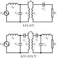
图2为传统的LCC-S和LCC-CCL复合式谐振补偿网络拓扑结构示意图;Figure 2 is a schematic diagram of the topology structure of a traditional LCC-S and LCC-CCL composite resonance compensation network;
图3为接收端高阶LC补偿的磁谐振无线电能传输系统电路拓扑族示意图;3 is a schematic diagram of a circuit topology family of a magnetic resonance wireless power transfer system with high-order LC compensation at the receiving end;
图4为接收端高阶LC补偿的磁谐振无线电能传输系统等效电路模型示意图;4 is a schematic diagram of an equivalent circuit model of a magnetic resonance wireless power transfer system with high-order LC compensation at the receiving end;
图5为具有二阶LC结构的磁谐振无线电能传输系统等效电路模型示意图;5 is a schematic diagram of an equivalent circuit model of a magnetic resonance wireless power transfer system with a second-order LC structure;
图6为本发明与传统LCC-S结构传输效率随负载变化仿真曲线图;FIG. 6 is a simulation curve diagram of the transmission efficiency of the present invention and the traditional LCC-S structure as a function of load;
图7为本发明与传统LCC-S结构传输效率随负载变化实验曲线图。FIG. 7 is an experimental graph showing the change of the transmission efficiency of the present invention and the traditional LCC-S structure with the load.
具体实施方式Detailed ways
为清楚地说明本发明接收端高阶LC补偿的磁谐振无线电能传输系统,结合实施例和附图对本发明作进一步说明,但不应以此限制本发明的保护范围。In order to clearly illustrate the high-order LC-compensated magnetic resonance wireless power transmission system at the receiving end of the present invention, the present invention will be further described with reference to the embodiments and accompanying drawings, but the protection scope of the present invention should not be limited by this.
实施例1Example 1
一种接收端高阶LC补偿的磁谐振无线电能传输系统,如图1所示,包括:发射端和接收端;A magnetic resonance wireless power transmission system with high-order LC compensation at the receiving end, as shown in Figure 1, includes: a transmitting end and a receiving end;
所述发射端包括发射端补偿网络和发射线圈LT,发射端补偿网络连接发射线圈LT,交流信号输入发射端补偿网络,发射端补偿网络将输入的电能转化为高频电压与电流信号,高频电压与电流信号输入发射线圈LT,发射线圈LT发出电能,通过发射端补偿网络使得发射线圈中的电流呈现恒流特性,发射线圈通过磁耦合将电能传输到接收线圈;;The transmitter includes a transmitter compensation network and a transmitter coil LT , the transmitter compensation network is connected to the transmitter coil LT , the AC signal is input to the transmitter compensation network, and the transmitter compensation network converts the input electrical energy into high-frequency voltage and current signals, The high-frequency voltage and current signals are input to the transmitting coil LT , the transmitting coil LT emits electric energy, and the current in the transmitting coil presents a constant current characteristic through the transmitting end compensation network, and the transmitting coil transmits the electric energy to the receiving coil through magnetic coupling;
所述接收端包括接收线圈LR和接收端补偿网络,接收端补偿网络包括具有若干阶LC的高阶LC结构;接收线圈LR连接接收端补偿网络,接收线圈LR接收发射线圈LT发出的电能,通过接收端补偿网络稳定传输效率。The receiving end includes a receiving coilLR and a receiving end compensation network, and the receiving end compensation network includes a high-order LC structure with several orders of LC; the receiving coilLR is connected to the receiving end compensation network, and the receiving coilLR receives and transmits the transmitting coilLT The electric energy is compensated by the receiving end to stabilize the transmission efficiency of the network.
本实施例提出了一种接收端高阶LC补偿的磁谐振无线电能传输系统,包括发射端和接收端,发射端为LCC串并联谐振结构,接收端设有高阶LC结构;其中,发射线圈电流仅与输入电压和发射端补偿网络中的参数有关,而与负载无关,当负载在理想状态下发生变化时,发射线圈的电流不会发生变化,发射线圈的恒定电流可使系统保持稳定的传输特性;接收端中,在高阶LC结构中LC数量为奇数时,接收端的输出表现出恒定电流特性,在高阶LC结构中LC数量为偶数时,接收端的输出表现出恒定电压特性;因此当负载变化时,接收端高阶LC补偿的磁谐振无线电能传输系统相比传统LCC-S和LCC-CCL拓扑结构具有更高的效率平稳度,并且在轻载时的效率远高于传统拓扑。This embodiment proposes a magnetic resonance wireless power transmission system with high-order LC compensation at the receiving end, including a transmitting end and a receiving end, the transmitting end is an LCC series-parallel resonance structure, and the receiving end is provided with a high-order LC structure; The current is only related to the input voltage and the parameters in the transmitter compensation network, but has nothing to do with the load. When the load changes in an ideal state, the current of the transmitter coil will not change, and the constant current of the transmitter coil can keep the system stable. Transmission characteristics; in the receiving end, when the number of LCs in the high-order LC structure is odd, the output of the receiving end exhibits constant current characteristics, and when the number of LCs in the high-order LC structure is even, the output of the receiving end exhibits constant voltage characteristics; therefore When the load changes, the magnetic resonance wireless power transfer system with high-order LC compensation at the receiving end has higher efficiency smoothness than the traditional LCC-S and LCC-CCL topologies, and the efficiency at light load is much higher than that of the traditional topology .
实施例2Example 2
在实施例1的基础上,如图1所示,本实施例发射端补偿网络为LCC串并联谐振网络,发射端还包括逆变电路,逆变电路的输入端连接直流电源,逆变电路的输出端连接发射端补偿网络,逆变电路将直流输入转化成交流信号输出。所述逆变电路为全桥逆变电路,逆变电路包括MOS管Q1、MOS管Q2、MOS管Q3和MOS管Q4;MOS管Q1的漏极和MOS管Q3的漏极连接,MOS管Q2的源极和MOS管Q4的源极连接,MOS管Q1的源极连接MOS管Q2的漏极,MOS管Q3的源极连接MOS管Q4的漏极,MOS管Q3的漏极和MOS管Q2的源极作为逆变电路的输入端,MOS管Q1的源极和MOS管Q4的漏极作为逆变电路的输出端。MOS管Q1、MOS管Q2、MOS管Q3和MOS管Q4均为N型MOS管,MOS管Q1、MOS管Q2、MOS管Q3和MOS管Q4的栅极均连接PWM信号。MOS管Q1、MOS管Q2、MOS管Q3和MOS管Q4的型号均为FQPF12N60。On the basis of
本实施例所述接收端还包括整流电路,整流电路的输入端连接高阶LC结构的输出端,整流电路的输出端连接负载。所述整流电路为全桥整流电路,整流电路包括二极管DR1、二极管DR2、二极管DR3和二极管DR4;二极管DR1的负极连接二极管DR2的负极,二极管DR3的正极连接二极管DR4的正极,二极管DR1的正极连接二极管DR3的负极,二极管DR2的正极连接二极管DR4的负极;二极管DR1的正极和二极管DR4的负极作为整流电路的输入端,二极管DR3的正极和二极管DR2的负极作为整流电路的输出端。所述整流电路还包括整流电容Co,整流电容Co两端分别连接整流电路的两输出端。所述整流电容Co为极性电容,整流电容Co的正极连接二极管DR2的负极,整流电容Co的负极连接二极管DR3的正极。The receiving end in this embodiment further includes a rectifier circuit, the input end of the rectifier circuit is connected to the output end of the high-order LC structure, and the output end of the rectifier circuit is connected to the load. The rectifier circuit is a full-bridge rectifier circuit, and the rectifier circuit includes a diodeDR1 , a diodeDR2 , a diodeDR3 , and a diodeDR4 ; the negative electrode of the diodeDR1 is connected to the negative electrode of the diodeDR2 , and the positive electrode of the diodeDR3 is connected to the diodeDR4 . The anode of the diode DR1 is connected to the cathode of the diode DR3 , the anode of the diode DR2 is connected to the cathode of the diode DR4 ; the anode of the diode DR1 and the cathode of the diode DR4 are used as the input terminals of the rectifier circuit, and the anode of the diode DR3 And the cathode of the diode DR2 is used as the output terminal of the rectifier circuit. The rectifier circuit further includes a rectifier capacitor Co , and two ends of the rectifier capacitor Co are respectively connected to two output ends of the rectifier circuit. The rectifying capacitor Co is a polar capacitor, the positive electrode of the rectifying capacitor Co is connected to the negative electrode of the diodeDR2 , and the negative electrode of the rectifying capacitor Co is connected to the positive electrode of the diodeDR3 .
本实施例中接收端补偿网络中的高阶LC结构中包括二至十阶LC结构,每一阶LC结构包括一个电容和一个电感,电容具有电容的第一连接端和第二连接端,电感具有电感的第一连接端和第二连接端,每一阶LC结构电容的第二连接端与电感的第一连接端连接;相邻两阶LC结构连接关系为:第二阶LC中电容的第二连接端连接上一阶LC电感的第一连接端,第二阶LC中电容的第一连接端连接上一阶LC电容的第一连接端;高阶LC结构中的第一阶LC结构的电容第一连接端和电容第二连接端作为高阶LC结构的输入端,高阶LC结构中的最后一阶LC结构的电容第一连接端和电感的第二连接端作为高阶LC结构的输出端。In this embodiment, the high-order LC structures in the compensation network at the receiving end include second to tenth-order LC structures, each order LC structure includes a capacitor and an inductor, and the capacitor has a first connecting end and a second connecting end of the capacitor, and the inductor There is a first connection end and a second connection end of the inductance, and the second connection end of the capacitor of each order LC structure is connected to the first connection end of the inductance; the connection relationship of the adjacent two order LC structures is: The second connection terminal is connected to the first connection terminal of the previous-order LC inductor, and the first connection terminal of the capacitor in the second-order LC is connected to the first connection terminal of the previous-order LC capacitor; the first-order LC structure in the high-order LC structure The first connection end of the capacitor and the second connection end of the capacitor are used as the input end of the high-order LC structure, and the first connection end of the capacitor and the second connection end of the inductor of the last-order LC structure in the high-order LC structure are used as the high-order LC structure. 's output.
实施例3Example 3
无线电能传输系统中为了实现接收线圈和发射线圈电感同频共振以及提高系统能量传输功率与效率,需通过在收发机构增加补偿网络的形式对收发线圈同时进行补偿。补偿网络在磁谐振耦合式无线充电系统中起着至关重要的作用,对收发机构双边补偿网络参数进行配置,可改变系统等效阻抗特性,从而最大限度的降低系统的无功功率,进而提高系统整体的功率因数和增加收发线圈之间的耦合度。补偿网络根据收发机构双边补偿网络串并联组合方式的不同,共有四种基本拓扑结构S-S、S-P、P-P、P-S。由于基本拓扑结构存在一定局限性,因此就在基本型拓扑结构之上引入了复合式谐振拓扑结构,主要有:LCL-S型、LCC-S型、LCL-LCL型、LCC-LCC型等拓扑结构。In the wireless power transmission system, in order to realize the co-frequency resonance of the inductance of the receiving coil and the transmitting coil and improve the power and efficiency of the system energy transmission, it is necessary to compensate the transceiver coil at the same time by adding a compensation network to the transceiver mechanism. The compensation network plays a vital role in the magnetic resonance coupled wireless charging system. The configuration of the bilateral compensation network parameters of the transceiver mechanism can change the equivalent impedance characteristics of the system, thereby minimizing the reactive power of the system and improving the The overall power factor of the system and increase the coupling between the transceiver coils. There are four basic topological structures S-S, S-P, P-P, and P-S in the compensation network according to the difference in the series-parallel combination of the bilateral compensation network of the transceiver mechanism. Due to the limitations of the basic topology, a composite resonant topology is introduced on top of the basic topology, mainly including: LCL-S, LCC-S, LCL-LCL, LCC-LCC and other topologies structure.
现有补偿网络与本发明相似的是LCC-S型和LCC-CCL型复合式谐振拓扑结构,LCC-S和LCC-CCL复合式谐振补偿网络拓扑结构示意图如图2所示,LCC-S和LCC-CCL复合式谐振补偿网络存在如下缺点:Similar to the present invention, the existing compensation network is the LCC-S type and LCC-CCL type composite resonance topological structure. The LCC-CCL composite resonance compensation network has the following disadvantages:
1、轻载情况下,系统传输效率相对较低。1. Under light load, the system transmission efficiency is relatively low.
2、系统传输效率稳定性较差。随着负载增大,系统传输效率迅速下降,不能适用于电池充电过程中的变负载充电模式。2. The system transmission efficiency and stability are poor. As the load increases, the transmission efficiency of the system drops rapidly, which cannot be applied to the variable load charging mode during battery charging.
本实施例提出一组接收端高阶LC补偿的磁谐振无线电能传输系统的电路拓扑族,电路拓扑族的电路结构如图3所示,所述电路拓扑族包括发射端的发射端补偿网络以及发射线圈,和接收端的接收线圈、接收端补偿网络,发射端补偿网络为LCC串并联谐振网络,接收端补偿网络为C(LC)n谐振网络,选择不同的n值对应不同的拓扑结构;因此本实施例的一组接收端高阶LC补偿的磁谐振无线电能传输系统的电路拓扑族可以被称为LCC-C(LC)n高阶拓扑族。This embodiment proposes a circuit topology family of a magnetic resonance wireless power transmission system with high-order LC compensation at the receiving end. The circuit structure of the circuit topology family is shown in FIG. 3 . The coil, the receiving coil at the receiving end, and the compensation network at the receiving end. The compensation network at the transmitting end is an LCC series-parallel resonant network, and the compensation network at the receiving end is a C(LC)n resonant network. Different n values are selected to correspond to different topological structures; A family of circuit topologies for a set of receive-side high-order LC-compensated magnetic resonance wireless power transfer systems of an embodiment may be referred to as the LCC-C(LC)n high-order topological family.
接收端补偿网络包括具有若干阶LC的高阶LC结构和接收端补偿电容CR,接收端补偿电容CR连接高阶LC结构的输入端;The receiving-end compensation network includes a high-order LC structure with several orders of LCs and a receiving-end compensation capacitorCR , and the receiving-end compensation capacitorCR is connected to the input end of the high-order LC structure;
高阶LC结构中包括n阶LC结构,每一阶LC结构包括一个电容和一个电感,电容具有电容的第一连接端和第二连接端,电感具有电感的第一连接端和第二连接端,每一阶LC结构电容的第二连接端与电感的第一连接端连接;相邻两阶LC结构连接关系为:第二阶LC中电容的第二连接端连接上一阶LC电感的第一连接端,第二阶LC中电容的第一连接端连接上一阶LC电容的第一连接端;高阶LC结构中的第一阶LC结构的电容第一连接端和电容第二连接端作为高阶LC结构的输入端,高阶LC结构中的最后一阶LC结构的电容第一连接端和电感的第二连接端作为高阶LC结构的输出端。接收端补偿电容CR连接电容第二连接端。The high-order LC structure includes n-order LC structures, each order LC structure includes a capacitor and an inductor, the capacitor has a first connection end and a second connection end of the capacitor, and the inductor has a first connection end and a second connection end of the inductance , the second connection end of each stage LC structure capacitor is connected to the first connection end of the inductor; the connection relationship between adjacent two-stage LC structures is: the second connection end of the capacitor in the second stage LC is connected to the first connection end of the previous stage LC inductor A connecting end, the first connecting end of the capacitor in the second-order LC is connected to the first connecting end of the previous-order LC capacitor; the first connecting end of the capacitor and the second connecting end of the capacitor of the first-order LC structure in the high-order LC structure As the input terminal of the high-order LC structure, the first connection terminal of the capacitor and the second connection terminal of the inductor of the last-order LC structure in the high-order LC structure are used as the output terminal of the high-order LC structure. The compensation capacitorCR at the receiving end is connected to the second connecting end of the capacitor.
在整个磁谐振无线电能传输系统中,谐振网络在电能传输过程中起到承上启下的作用,对于发射端的LCC串并联谐振网络,其主要的作用是将电源所输入的电能通过LCC串并联谐振网络转化为所需的高频电压与电流信号,加载到发射线圈中,进而高效的将电能发射出去。通过合理的设计LCC串并联谐振网络的电感、电容参数,提高其可靠性与适应性。另一方面,对于接收端,通过合理设计接收线圈的电感值与尺寸,并合理选择接收端的C(LC)n谐振网络参数,可使得系统传输效率稳定度提高,当负载变化时保证传输效率的稳定。In the entire magnetic resonance wireless power transmission system, the resonant network plays a linking role in the power transmission process. For the LCC series-parallel resonant network at the transmitting end, its main function is to convert the power input from the power source through the LCC series-parallel resonant network. For the required high-frequency voltage and current signals, it is loaded into the transmitting coil, and then the power is transmitted efficiently. By reasonably designing the inductance and capacitance parameters of the LCC series-parallel resonant network, its reliability and adaptability are improved. On the other hand, for the receiving end, by reasonably designing the inductance value and size of the receiving coil and reasonably selecting the C(LC)n resonant network parameters of the receiving end, the stability of the transmission efficiency of the system can be improved, and the transmission efficiency can be guaranteed when the load changes. Stablize.
图3中输入的交流信号通过逆变电路发出,逆变电路如图1所示,逆变电路的输入端连接直流电源,逆变电路的输出端连接发射端补偿网络,逆变电路将直流输入转化成交流信号输出;所述逆变电路为全桥逆变电路,逆变电路包括MOS管Q1、MOS管Q2、MOS管Q3和MOS管Q4;MOS管Q1的漏极和MOS管Q3的漏极连接,MOS管Q2的源极和MOS管Q4的源极连接,MOS管Q1的源极连接MOS管Q2的漏极,MOS管Q3的源极连接MOS管Q4的漏极,MOS管Q3的漏极和MOS管Q2的源极作为逆变电路的输入端,MOS管Q1的源极和MOS管Q4的漏极作为逆变电路的输出端。The AC signal input in Figure 3 is sent out through the inverter circuit. The inverter circuit is shown in Figure 1. The input terminal of the inverter circuit is connected to the DC power supply, and the output terminal of the inverter circuit is connected to the transmitter compensation network. The inverter circuit is a full-bridge inverter circuit, and the inverter circuit includes a MOS tube Q1 , a MOS tube Q2 , a MOS tube Q3 and a MOS tube Q4 ; the drain of the MOS tube Q1 and theThe drain of the MOS transistorQ3 is connected, the source of the MOS transistorQ2 is connected to the source of the MOS transistorQ4 , the source of the MOS transistor Q1 is connected to the drain of the MOS transistorQ2 , and the source of the MOS transistorQ3 is connected The drain of the MOS transistorQ4 , the drain of the MOS transistorQ3 and the source of the MOS transistorQ2 are used as the input terminals of the inverter circuit, and the sourceof the MOS transistor Q1 and the drain of the MOS transistorQ4 are used as the inverter circuit. 's output.
对本实施例的一组接收端高阶LC补偿的磁谐振无线电能传输系统电路拓扑族中的发射端和接收端谐振网络电路特性进行分析,可将图3电路进行等效得到如图4的接收端高阶LC补偿的磁谐振无线电能传输系统等效电路模型。By analyzing the circuit characteristics of the transmitter and receiver resonant networks in the circuit topology family of a magnetic resonance wireless power transmission system with high-order LC compensation at the receiver of this embodiment, the circuit in Figure 3 can be equivalently obtained to obtain the receiver shown in Figure 4. Equivalent circuit model of magnetic resonance wireless power transfer system with high-end high-order LC compensation.
ZM为接收线圈和发射线圈之间的互感,式中ω为电路的谐振角频率,ZM和其他阻抗的表达式如下:ZM is the mutual inductance between the receiving coil and the transmitting coil, where ω is the resonant angular frequency of the circuit, and the expressions of ZM and other impedances are as follows:

根据KVL方程,接收端回路在谐振状态下有以下关系:According to the KVL equation, the receiver loop has the following relationship in the resonance state:

在设置补偿网络电感电容参数时,需要保证每一个网孔电抗之和为零,使得系统工作在谐振状态。When setting the inductance and capacitance parameters of the compensation network, it is necessary to ensure that the sum of the reactance of each mesh is zero, so that the system works in a resonance state.


从发射线圈电流IT表达式可知,无论拓扑族的n值如何,该拓扑族的所有拓扑传输线圈都具有相同的表达式,它仅与输入电压和补偿网络中参数有关,而与负载无关。这意味着该拓扑族的拓扑结构具有相同的特性,即当负载在理想状态下发生变化时,传输线圈的电流不会发生变化。该拓扑族发射线圈的恒定电流可使系统保持稳定的传输特性。From the expression of the transmitting coil current IT , it can be known that no matter what the n value of the topology family is, all the topological transmission coils of the topology family have the same expression, which is only related to the input voltage and the parameters in the compensation network, and has nothing to do with the load. This means that the topologies of this topology family have the same property that the current in the transmission coil does not change when the load changes under ideal conditions. The constant current of the transmitting coil of this topology family can keep the system stable transmission characteristics.
由接收端的输出电流IO的表达式可知。当n为奇数时,输出电流的表达式与互感、补偿网络参数和输入电压有关,此时,该拓扑族的拓扑输出电流与负载无关,并表现出恒定的电流特性。当n为偶数时,输出电流表达式与互感、补偿网络参数、输入电压和负载有关,且输出电流与输入电压呈正相关,与负载呈负相关。这意味着,当n为偶数时,该拓扑族的拓扑输出电压与负载无关,并表现出恒定的电压特性。It can be known from the expression of the output currentIO of the receiving end. When n is an odd number, the expression of the output current is related to the mutual inductance, compensation network parameters and input voltage. At this time, the topology output current of this topology family is independent of the load and exhibits a constant current characteristic. When n is an even number, the output current expression is related to mutual inductance, compensation network parameters, input voltage and load, and the output current is positively correlated with the input voltage and negatively correlated with the load. This means that when n is an even number, the topological output voltage of this topology family is independent of the load and exhibits a constant voltage characteristic.
考虑到本实施例一组LCC-C(LC)n高阶拓扑族的复杂度,在此仅取n=0的LCC-S传统拓扑和n=2的具有二阶LC结构的磁谐振无线电能传输系统的LCC-C(LC)2电路拓扑对系统传输效率进行理论对比分析,LCC-C(LC)2电路拓扑的等效模型如图5具有二阶LC结构的磁谐振无线电能传输系统等效电路模型示意图所示;Considering the complexity of a set of LCC-C(LC)n high-order topology families in this embodiment, only the traditional LCC-S topology with n=0 and the magnetic resonance wireless energy with second-order LC structure with n=2 are taken here. The LCC-C(LC)2 circuit topology of the transmission system is used to compare and analyze the system transmission efficiency theoretically. The equivalent model of the LCC-C(LC)2 circuit topology is shown in Figure 5. Magnetic resonance wireless power transmission system with second-order LC structure, etc. The schematic diagram of the effective circuit model is shown;
对五个电压网孔列写KVL方程:Write the KVL equation for the five voltage mesh columns:


UIN=R1IIN-ZCPCIO=R1DIO-ZCPCIO=(R1D-ZCPC)IO=EIOUIN =R1 IIN -ZCP CO =R1 DIO -ZCP CO =(R1 DZCP C)IO =EIO

求解得LCC-C(LC)2电路拓扑的效率表达式为:The efficiency expression of the LCC-C(LC)2 circuit topology is solved as:

同理,上述方法求解n=0的LCC-S传统拓扑,可得:In the same way, the above method solves the traditional topology of LCC-S with n=0, we can get:

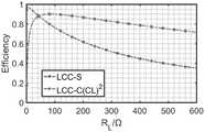
通过MATLAB仿真效率与负载曲线关系如图6所示,分析可得:(1)当负载变化时,LCC-C(LC)2电路拓扑的传输效率相比传统拓扑LCC-S具有更高的平稳度。(2)LCC-C(LC)2电路拓扑轻载时的效率远高于LCC-S。The relationship between the efficiency and the load curve simulated by MATLAB is shown in Figure 6. The analysis can be obtained: (1) When the load changes, the transmission efficiency of the LCC-C(LC)2 circuit topology has a higher stability than the traditional topology LCC-S. Spend. (2) The efficiency of the LCC-C(LC)2 circuit topology at light load is much higher than that of the LCC-S.
通过图7本发明与传统LCC-S结构传输效率随负载变化实验曲线图可以看出,在接收端具有二阶LC结构的磁谐振无线电能传输系统与传统LCC-S结构传输效率随负载变化实验中,当负载变化时,LCC-C(LC)n高阶拓扑族相比传统拓扑具有更高的效率平稳度。LCC-C(LC)n高阶拓扑族在轻载时的效率远高于传统拓扑。It can be seen from Fig. 7 that the transmission efficiency of the present invention and the traditional LCC-S structure changes with the load. It can be seen that the transmission efficiency of the magnetic resonance wireless power transmission system with the second-order LC structure at the receiving end and the traditional LCC-S structure change with the load. , the LCC-C(LC)n high-order topology family has higher efficiency smoothness than the conventional topology when the load changes. The efficiency of the LCC-C(LC)n high-order topology family at light loads is much higher than that of conventional topologies.
实施例4Example 4
在实施例3的基础上,本实施例发射端还包括逆变电路,接收端还包括整流电路,如图1所示,逆变电路的输入端连接直流电源,输出端连接发射端补偿网络,逆变电路将直流输入转化成交流信号输出;整流电路包括功率二极管DR1、二极管DR2、二极管DR3、二极管DR4,滤波电容CO,负载RLoad。整流电路的输入端连接高阶LC结构的输出端,整流电路的输出端连接负载。整流电路作用是将接收端高阶LC结构谐振网络接收到的高频交流正弦波经过接收端二极管DR1、二极管DR2、二极管DR3、二极管DR4变换为高频馒头波,再经过滤波电容CO将高频馒头波变换为直流电输送给负载设备使用。On the basis of
显然,本发明的上述实施例仅仅是为清楚地说明本发明所作的举例,而并非是对本发明的实施方式的限定。对于所属领域的普通技术人员来说,在上述说明的基础上还可以做出其它不同形式的变化或变动。这里无需也无法对所有的实施方式予以穷举。凡在本发明的精神和原则之内所作的任何修改、等同替换和改进等,均应包含在本发明权利要求的保护范围之内。Obviously, the above-mentioned embodiments of the present invention are only examples for clearly illustrating the present invention, and are not intended to limit the embodiments of the present invention. For those of ordinary skill in the art, changes or modifications in other different forms can also be made on the basis of the above description. There is no need and cannot be exhaustive of all implementations here. Any modifications, equivalent replacements and improvements made within the spirit and principle of the present invention shall be included within the protection scope of the claims of the present invention.
Claims (10)


Priority Applications (1)
| Application Number | Priority Date | Filing Date | Title |
|---|---|---|---|
| CN202210193226.2ACN114552800A (en) | 2022-02-28 | 2022-02-28 | A Magnetic Resonance Wireless Power Transmission System with High-Order LC Compensation at the Receiver |
Applications Claiming Priority (1)
| Application Number | Priority Date | Filing Date | Title |
|---|---|---|---|
| CN202210193226.2ACN114552800A (en) | 2022-02-28 | 2022-02-28 | A Magnetic Resonance Wireless Power Transmission System with High-Order LC Compensation at the Receiver |
Publications (1)
| Publication Number | Publication Date |
|---|---|
| CN114552800Atrue CN114552800A (en) | 2022-05-27 |
Family
ID=81662133
Family Applications (1)
| Application Number | Title | Priority Date | Filing Date |
|---|---|---|---|
| CN202210193226.2APendingCN114552800A (en) | 2022-02-28 | 2022-02-28 | A Magnetic Resonance Wireless Power Transmission System with High-Order LC Compensation at the Receiver |
Country Status (1)
| Country | Link |
|---|---|
| CN (1) | CN114552800A (en) |
Cited By (1)
| Publication number | Priority date | Publication date | Assignee | Title |
|---|---|---|---|---|
| CN117977831A (en)* | 2024-03-27 | 2024-05-03 | 广东工业大学 | A constant power control method for wireless power transmission system |
Citations (3)
| Publication number | Priority date | Publication date | Assignee | Title |
|---|---|---|---|---|
| CN106100345A (en)* | 2016-07-07 | 2016-11-09 | 上海交通大学 | Bilateral T S compensation topology and characteristic parameter matching method for wireless power transmission |
| CN107769573A (en)* | 2017-11-20 | 2018-03-06 | 东南大学 | The WPT system constant current constant voltage of bilateral LCC networks exports adjustable parameter setting method |
| CN113572274A (en)* | 2021-08-17 | 2021-10-29 | 广东工业大学 | Resonant wireless power transmission system with LCC-LCLCC compensation network |
- 2022
- 2022-02-28CNCN202210193226.2Apatent/CN114552800A/enactivePending
Patent Citations (3)
| Publication number | Priority date | Publication date | Assignee | Title |
|---|---|---|---|---|
| CN106100345A (en)* | 2016-07-07 | 2016-11-09 | 上海交通大学 | Bilateral T S compensation topology and characteristic parameter matching method for wireless power transmission |
| CN107769573A (en)* | 2017-11-20 | 2018-03-06 | 东南大学 | The WPT system constant current constant voltage of bilateral LCC networks exports adjustable parameter setting method |
| CN113572274A (en)* | 2021-08-17 | 2021-10-29 | 广东工业大学 | Resonant wireless power transmission system with LCC-LCLCC compensation network |
Cited By (1)
| Publication number | Priority date | Publication date | Assignee | Title |
|---|---|---|---|---|
| CN117977831A (en)* | 2024-03-27 | 2024-05-03 | 广东工业大学 | A constant power control method for wireless power transmission system |
Similar Documents
| Publication | Publication Date | Title |
|---|---|---|
| CN109617250B (en) | An anti-offset wireless power transmission system based on combined topology | |
| CN107769573B (en) | The WPT system constant current constant voltage of bilateral LCC network exports adjustable parameter setting method | |
| CN112583134B (en) | Variable circuit topology capable of switching wireless power transmission coil and compensation capacitor | |
| CN105720582B (en) | A kind of particular harmonic eliminates radio energy transmission system and its design method | |
| CN109217496B (en) | Parameter analysis method for bilateral LCC compensation circuit in wireless electric energy transmission system | |
| CN101860237A (en) | High power factor constant current circuit and power supply | |
| CN106787253A (en) | ECPT system based on T‑Π composite resonant network and its parameter design method | |
| CN112421797B (en) | Wireless charging system power dilatation topological structure | |
| CN107069999A (en) | The parameter setting method of the radio energy transmission system constant current output of bilateral LC networks | |
| CN108832724A (en) | ECPT System and Its Parameter Design Method Using Compensation Inductance to Transmit Signal | |
| CN110429691A (en) | A kind of constant current-constant-voltage charge radio energy transmission system based on half-bridge switching | |
| CN113794287B (en) | Constant-current-constant-voltage charging wireless power transmission system based on double-channel T-shaped circuit | |
| CN113572274A (en) | Resonant wireless power transmission system with LCC-LCLCC compensation network | |
| CN113675956A (en) | A staggered anti-offset constant voltage resonant wireless power transmission system | |
| CN109067184B (en) | An inductive power transmission system with seamless switching of constant current and constant voltage | |
| CN112003387B (en) | Constant voltage constant current wireless charging system based on improved S/S compensation network | |
| CN114552800A (en) | A Magnetic Resonance Wireless Power Transmission System with High-Order LC Compensation at the Receiver | |
| CN116470655A (en) | Efficient anti-offset magnetic resonance type wireless power transmission system and control method thereof | |
| CN216290360U (en) | A wireless power supply system applied to on-line monitoring equipment of high-voltage transmission lines | |
| CN110112836A (en) | A kind of magnet coupled resonant type wireless transmission system and control method | |
| CN107769571A (en) | A kind of double CLC structures Electric field wireless transmitting systems and its optimization method | |
| CN110797991A (en) | A kW-level power wireless power transmission system based on relay converter | |
| CN204334131U (en) | A power transmitter and wireless power transmission device | |
| CN115459461B (en) | Multi-relay wireless energy information parallel transmission system based on bipolar coils | |
| CN109560617B (en) | General Model and Modeling Method for Arbitrary Higher-Order Resonant Circuits |
Legal Events
| Date | Code | Title | Description |
|---|---|---|---|
| PB01 | Publication | ||
| PB01 | Publication | ||
| SE01 | Entry into force of request for substantive examination | ||
| SE01 | Entry into force of request for substantive examination |