CN114552579A - Power distribution network maximum power supply capacity calculation method considering low-voltage transformer area flexible interconnection - Google Patents
Power distribution network maximum power supply capacity calculation method considering low-voltage transformer area flexible interconnectionDownload PDFInfo
- Publication number
- CN114552579A CN114552579ACN202210436526.9ACN202210436526ACN114552579ACN 114552579 ACN114552579 ACN 114552579ACN 202210436526 ACN202210436526 ACN 202210436526ACN 114552579 ACN114552579 ACN 114552579A
- Authority
- CN
- China
- Prior art keywords
- power
- distribution network
- transformer
- distribution
- capacity
- Prior art date
- Legal status (The legal status is an assumption and is not a legal conclusion. Google has not performed a legal analysis and makes no representation as to the accuracy of the status listed.)
- Granted
Links
Images


Classifications
- H—ELECTRICITY
- H02—GENERATION; CONVERSION OR DISTRIBUTION OF ELECTRIC POWER
- H02J—CIRCUIT ARRANGEMENTS OR SYSTEMS FOR SUPPLYING OR DISTRIBUTING ELECTRIC POWER; SYSTEMS FOR STORING ELECTRIC ENERGY
- H02J3/00—Circuit arrangements for AC mains or AC distribution networks
- H—ELECTRICITY
- H02—GENERATION; CONVERSION OR DISTRIBUTION OF ELECTRIC POWER
- H02J—CIRCUIT ARRANGEMENTS OR SYSTEMS FOR SUPPLYING OR DISTRIBUTING ELECTRIC POWER; SYSTEMS FOR STORING ELECTRIC ENERGY
- H02J3/00—Circuit arrangements for AC mains or AC distribution networks
- H02J3/04—Circuit arrangements for AC mains or AC distribution networks for connecting networks of the same frequency but supplied from different sources
- H02J3/06—Controlling transfer of power between connected networks; Controlling sharing of load between connected networks
- H—ELECTRICITY
- H02—GENERATION; CONVERSION OR DISTRIBUTION OF ELECTRIC POWER
- H02J—CIRCUIT ARRANGEMENTS OR SYSTEMS FOR SUPPLYING OR DISTRIBUTING ELECTRIC POWER; SYSTEMS FOR STORING ELECTRIC ENERGY
- H02J3/00—Circuit arrangements for AC mains or AC distribution networks
- H02J3/38—Arrangements for parallely feeding a single network by two or more generators, converters or transformers
- H02J3/381—Dispersed generators
- H—ELECTRICITY
- H02—GENERATION; CONVERSION OR DISTRIBUTION OF ELECTRIC POWER
- H02J—CIRCUIT ARRANGEMENTS OR SYSTEMS FOR SUPPLYING OR DISTRIBUTING ELECTRIC POWER; SYSTEMS FOR STORING ELECTRIC ENERGY
- H02J2203/00—Indexing scheme relating to details of circuit arrangements for AC mains or AC distribution networks
- H02J2203/10—Power transmission or distribution systems management focussing at grid-level, e.g. load flow analysis, node profile computation, meshed network optimisation, active network management or spinning reserve management
- H—ELECTRICITY
- H02—GENERATION; CONVERSION OR DISTRIBUTION OF ELECTRIC POWER
- H02J—CIRCUIT ARRANGEMENTS OR SYSTEMS FOR SUPPLYING OR DISTRIBUTING ELECTRIC POWER; SYSTEMS FOR STORING ELECTRIC ENERGY
- H02J2203/00—Indexing scheme relating to details of circuit arrangements for AC mains or AC distribution networks
- H02J2203/20—Simulating, e g planning, reliability check, modelling or computer assisted design [CAD]
- Y—GENERAL TAGGING OF NEW TECHNOLOGICAL DEVELOPMENTS; GENERAL TAGGING OF CROSS-SECTIONAL TECHNOLOGIES SPANNING OVER SEVERAL SECTIONS OF THE IPC; TECHNICAL SUBJECTS COVERED BY FORMER USPC CROSS-REFERENCE ART COLLECTIONS [XRACs] AND DIGESTS
- Y02—TECHNOLOGIES OR APPLICATIONS FOR MITIGATION OR ADAPTATION AGAINST CLIMATE CHANGE
- Y02E—REDUCTION OF GREENHOUSE GAS [GHG] EMISSIONS, RELATED TO ENERGY GENERATION, TRANSMISSION OR DISTRIBUTION
- Y02E60/00—Enabling technologies; Technologies with a potential or indirect contribution to GHG emissions mitigation
- Y02E60/60—Arrangements for transfer of electric power between AC networks or generators via a high voltage DC link [HVCD]
Landscapes
- Engineering & Computer Science (AREA)
- Power Engineering (AREA)
- Supply And Distribution Of Alternating Current (AREA)
Abstract
Description
Translated fromChinese技术领域technical field
本发明属于配电网规划与运行技术领域,尤其是计及低压台区柔性互联的配电网最大供电能力计算方法。The invention belongs to the technical field of distribution network planning and operation, in particular to a method for calculating the maximum power supply capacity of a distribution network considering the flexible interconnection of low-voltage station areas.
背景技术Background technique
随着全球能源结构向清洁、低碳化转型,我国已提出“2030碳达峰、2060碳中和”的宏伟目标。配电网作为连接用户与大电网的枢纽,将面临大规模分布式电源(distributedgenerations, DG)、电动汽车、储能、电采暖等新低碳元素的接入,由此引发的系统承载能力不足、负载不均衡、电压越限等问题给配电网规划运行带来严峻挑战。With the transformation of the global energy structure to a clean and low-carbon energy, my country has put forward the ambitious goal of "carbon peaking by 2030 and carbon neutrality by 2060". As a hub connecting users with large power grids, the distribution network will face the access of new low-carbon elements such as large-scale distributed generation (DG), electric vehicles, energy storage, and electric heating, resulting in insufficient system carrying capacity, Problems such as unbalanced load and out-of-limit voltage have brought severe challenges to the planning and operation of distribution networks.
从网架升级角度,柔性互联技术是解决上述问题的有效手段,其含义为采用电力电子柔性互联设备(flexible interconnected devices, FID)升级/构建配电网联络节点/通道,利用FID的动态潮流控制能力以及故障隔离能力,实现配电网柔性闭环运行,具体包括:①实时共享互联设备的容量,包括正常运行均衡负载以及故障负荷快速转供;②动态输出无功,平抑系统电压波动;③直流母线接入数据中心等直流负荷,减少变流环节,提高能量转换效率。From the perspective of grid upgrade, flexible interconnection technology is an effective means to solve the above problems, which means using power electronic flexible interconnected devices (FID) to upgrade/build distribution network connection nodes/channels, using FID for dynamic power flow control It can realize flexible closed-loop operation of distribution network, including: ①Real-time sharing of the capacity of interconnected equipment, including load balancing in normal operation and fast transfer of faulted loads; ②Dynamic output of reactive power to stabilize system voltage fluctuations; ③DC The busbar is connected to DC loads such as data centers, reducing the converter links and improving the energy conversion efficiency.
配电网柔性互联技术已经历了10余年的理论研究,并开展了一些示范工程建设,主要针对高压和中压配电网,例如英国的Network Equilibrium项目,北京怀柔的三端柔性环网示范工程等,而0.4kV的低压柔性互联配电网(low-volatge flexible distributionnetwork, LVFDN)研究相对较少。相对柔性中压互联,低压FID由于技术难度与成本相对较低、应用场景多样,将有潜力率先规模化应用,形成相邻台区广泛柔性互联的“蜂窝状配电网”。The flexible interconnection technology of distribution network has undergone more than 10 years of theoretical research, and some demonstration projects have been carried out, mainly for high-voltage and medium-voltage distribution networks, such as the Network Equilibrium project in the United Kingdom, and the three-terminal flexible ring network demonstration project in Huairou, Beijing. etc., while 0.4kV low-voltage flexible distribution network (low-volatge flexible distribution network, LVFDN) research is relatively rare. Relatively flexible medium-voltage interconnection, low-voltage FID has the potential to take the lead in large-scale application due to its relatively low technical difficulty and cost, and various application scenarios, forming a "honeycomb distribution network" with extensive flexible interconnection in adjacent stations.
文献《考虑规模化快充负荷的低压互联配电台区风险评估》对比了配电台区中快充负荷分散接入的传统方式和台区低压侧互联的新型接入方式,对台区柔性互联风险进行了评估;文献《交直流配电台区建设改造模式研究》以低压配电台区的整体负荷均衡为目标,提出基于直流线路的低压配电台区负荷转供方法;文献《规模化电动汽车负荷的柔性台区协同经济调度》提出了考虑规模化电动汽车快充负荷的柔性台区经济调度方法;文献《低压智能柔性互连交直流混合配电网设计》设计了海宁某台区基于柔性互连的低压交直流混供配电网方案。示范工程方面,英国2014年启动了FUN-LV工程,其低压FID规模达到24个,展示了较好的经济、社会和环境效益;宁波北仑开展了国内最早的柔性台区示范工程;山东济南建成了基于台区智能融合终端的低压柔直互联系统。The document "Risk Assessment of Low-Voltage Interconnected Distribution Stations Considering Scaled Fast-Charging Loads" compares the traditional method of distributed access of fast-charging loads in the distribution station area and the new access method of low-voltage side interconnection in the station area. The risk of interconnection has been assessed; the document "Research on the Construction and Reconstruction Mode of AC and DC Distribution Station Areas" aims at the overall load balance of the low-voltage distribution station area, and proposes a load transfer method for the low-voltage distribution station area based on DC lines; the document "Scale Coordinated Economic Dispatching of Flexible Station Areas with Scaled Electric Vehicle Loads" proposes a flexible station area economic dispatch method considering the fast-charging load of large-scale electric vehicles. A low-voltage AC-DC hybrid power supply and distribution network scheme based on flexible interconnection. In terms of demonstration projects, the UK launched the FUN-LV project in 2014, and its low-voltage FID scale reached 24, showing good economic, social and environmental benefits; Ningbo Beilun launched the earliest flexible platform demonstration project in China; Shandong Jinan completed A low-voltage flexible direct interconnection system based on intelligent integrated terminals in the Taiwan area has been developed.
上述研究对LVFDN结构、风险评估、调度方法等进行了研究,然而对于LVFDN的供电能力研究尚属空白。最大供电能力(total supply capability, TSC)是配电网规划、评估以及安全分析的经典指标,针对传统10kV中压配网,TSC已建立了从模型算法到应用的完善体系,已对中压柔性互联配电网的供电能力进行了如文献《柔性配电网的最大供电能力模型》的研究。文献《Newton C, Lang P, Terry S. Field trial results of powerelectronics in low-voltage distribution networks》也提及了N-1故障下柔性设备对负荷的柔性转带策略,但只考虑了配变通过柔性互联装置互为N-1备用的情况。这些研究对于LVFDN的TSC研究具有借鉴意义,但是在FID负荷连续分配、N-1后的负荷二次转供等难点问题上未有涉及。LVFDN的TSC模型由于中低压负荷转供的双重约束将更加复杂,现有求解方法不再适用,需要开展新的研究。The above studies have studied the LVFDN structure, risk assessment, scheduling methods, etc., but the research on the power supply capacity of LVFDN is still blank. The maximum power supply capability (TSC) is a classic indicator for distribution network planning, evaluation and safety analysis. For the traditional 10kV medium-voltage distribution network, TSC has established a complete system from model algorithm to application, and has established a comprehensive system for medium-voltage flexibility. The power supply capacity of the interconnected distribution network has been studied in the literature "Maximum Power Supply Capacity Model of Flexible Distribution Network". The document "Newton C, Lang P, Terry S. Field trial results of powerelectronics in low-voltage distribution networks" also mentioned the flexible transfer strategy of flexible equipment to load under N-1 fault, but only considered the distribution transformer through flexible The case where interconnected devices are N-1 backups for each other. These studies have reference significance for the TSC study of LVFDN, but they are not involved in the continuous distribution of FID load and the secondary transfer of load after N-1. The TSC model of LVFDN will be more complicated due to the dual constraints of medium and low voltage load transfer, and the existing solution methods are no longer applicable, and new research is required.
发明内容SUMMARY OF THE INVENTION
本发明的目的在于克服现有技术的不足,提出计及低压台区柔性互联的配电网最大供电能力计算方法,通过分析台区柔性互联的配电网中-低压协同运行方式,建立考虑台区柔性互联、负荷多级转供等约束的配电网TSC模型,针对所提出模型特征进行求解得到配电网最大供电能力的计算结果。The purpose of the present invention is to overcome the deficiencies of the prior art, and propose a calculation method for the maximum power supply capacity of the distribution network that takes into account the flexible interconnection of the low-voltage station area. The TSC model of the distribution network with the constraints of flexible interconnection of districts and multi-level transfer of loads, etc., is solved according to the characteristics of the proposed model to obtain the calculation result of the maximum power supply capacity of the distribution network.
本发明解决其技术问题是采取以下技术方案实现的:The present invention solves its technical problem by adopting the following technical solutions to realize:
计及低压台区柔性互联的配电网最大供电能力计算方法,包括以下步骤:The calculation method of the maximum power supply capacity of the distribution network considering the flexible interconnection of the low-voltage station area includes the following steps:
步骤1、根据台区柔性互联的配电网的结构及其特点,建立多种约束条件的配电网TSC模型;
步骤2、获取台区柔性互联的配电网参数;
步骤3、根据步骤1中构建的配电网TSC模型和步骤2中台区柔性互联的配电网参数进行解算,得到配电网最大供电能力的数值。Step 3: Calculate according to the distribution network TSC model constructed in
而且,所述步骤1中约束条件包括:配电网特性约束、运行约束和N-1安全约束。Moreover, the constraints in the
而且,所述配电网特性约束包括:Furthermore, the distribution network characteristic constraints include:
配电网特性约束1、配电网节点功率从电网流出方向为正,注入为负;Distribution
配电网特性约束2、由于城市电网线路短并且网损小,简化馈线出口潮流包括网损,并采用直流潮流计算;Distribution
配电网特性约束3、故障集考虑主变故障退运、馈线出口线路故障退运和配变故障退运,不考虑10kV支线故障以及0.4kV线路故障;Distribution network characteristic constraints 3. The fault set considers the failure of the main transformer, the failure of the feeder outlet line and the failure of the distribution transformer, and does not consider the failure of the 10kV branch line and the failure of the 0.4kV line;
配电网特性约束4、城市地区分布式电源渗透率低,节点净功率呈中压流向低压供电特性,若不考虑DG,则转化为纯负荷情况的供电能力计算,否则将将DG简化功率为负的负荷进行计算。Constraints of distribution network characteristics 4. The penetration rate of distributed power generation in urban areas is low, and the net power of nodes exhibits the characteristics of medium-voltage to low-voltage power supply. If DG is not considered, it will be converted into the calculation of power supply capacity under pure load conditions, otherwise, the simplified power of DG will be Negative loads are calculated.
而且,所述运行约束为:配电网台区个数为n,台区的配变高压进线净功率等于配变所供用户总视在功率以及与台区互联的FID端口注入功率之和,考虑正常运行时配变所供用户总视在功率以及与台区互联的FID端口注入功率之和需要小于配变的额定容量,以及不允许配变潮流倒送的约束,则:Moreover, the operating constraints are: the number of distribution network stations isn , and the net power of the distribution transformer high-voltage incoming line in the station area is equal to the sum of the total apparent power provided by the distribution transformer and the injected power of the FID port interconnected with the station area. , considering that the sum of the total apparent power provided by the distribution transformer and the injected power of the FID port interconnected with the station area needs to be less than the rated capacity of the distribution transformer during normal operation, and the constraints that the power flow of the distribution transformer is not allowed to be reversed, then:

其中,


FID端口转移功率需满足端口容量约束为:The FID port transfer power needs to meet the port capacity constraints as follows:

FID的各个端口功率之和满足基尔霍夫方程,并且忽略装置自身损耗:The sum of the power of each port of the FID satisfies the Kirchhoff equation and ignores the loss of the device itself:

其中,

在直流潮流的条件下,配电网潮流简化为功率平衡方程,线路

其中,


主变

其中


而且,所述N-1安全约束为:若故障集为


主变容量约束为:The main variable capacity constraints are:

故障发生时,负荷


其中,


而且,所述步骤1中构建的配电网TSC模型为:所有用户负荷

其中:


其中,


而且,所述步骤2中台区柔性互联的配电网参数包括:配电网结构参数、主变集合、馈线集合和配变集合。Moreover, in the
而且,所述步骤3包括以下步骤:Moreover, the step 3 includes the following steps:
步骤3.1、根据配电网结构参数,计算用户视在功率

步骤3.2、生成故障集


步骤3.3、令
步骤3.4、对主变集合、馈线集合、配变集合的元素依次进行N-1安全校验,同时取
步骤3.5、在新拓扑下,计及运行约束和N-1安全约束,并判断此时的i是否达到最大,若达到最大,则进行步骤3.6,否则使
步骤3.6、判断

本发明的优点和积极效果是:The advantages and positive effects of the present invention are:
本发明通过分析台区柔性互联的配电网中-低压协同运行方式,建立考虑台区柔性互联、负荷多级转供等约束的配电网TSC模型,并针对所提出模型特征进行求解得到配电网最大供电能力的计算结果。本发明考虑了LVFDN中-低压协同的灵活运行方式,能够更有效地利用负荷转供能力,进一步提升可靠性;同时建立了考虑台区柔性互联、负荷多级转供的LVFDN的TSC模型;并且针对所提出模型的非线性非凸规划特征,提出了基于分支定界算法的TSC模型求解方法,能够精确求解LVFDN的TSC数值以及变化。The invention establishes a distribution network TSC model considering the constraints of flexible interconnection and multi-level load transfer in the station area by analyzing the medium-low voltage cooperative operation mode of the distribution network in the flexible interconnection of the station area, and solves the characteristics of the proposed model to obtain the distribution network. The calculation result of the maximum power supply capacity of the grid. The present invention considers the flexible operation mode of LVFDN medium-low voltage coordination, can more effectively utilize the load transfer capability, and further improves reliability; at the same time, a TSC model of LVFDN considering the flexible interconnection of station areas and multi-level load transfer is established; and Aiming at the nonlinear non-convex programming characteristics of the proposed model, a TSC model solution method based on branch and bound algorithm is proposed, which can accurately solve the TSC value and variation of LVFDN.
附图说明Description of drawings
图1为计及规模化台区柔性互联配电网典型结构图;Figure 1 is a typical structure diagram of a flexible interconnected distribution network taking into account the large-scale platform area;
图2为LVFDN中-低压协同运行示意图;Figure 2 is a schematic diagram of LVFDN medium-low voltage coordinated operation;
图3为本发明分支定界算法流程图;Fig. 3 is the flow chart of branch and bound algorithm of the present invention;
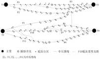
图4为本发明5个低压FID的LVFDN算例拓扑图。FIG. 4 is a topology diagram of an LVFDN calculation example of five low-voltage FIDs of the present invention.
具体实施方式Detailed ways
以下结合附图对本发明做进一步详述。The present invention will be described in further detail below in conjunction with the accompanying drawings.
计及低压台区柔性互联的配电网最大供电能力计算方法,包括以下步骤:The calculation method of the maximum power supply capacity of the distribution network considering the flexible interconnection of the low-voltage station area includes the following steps:
步骤1、根据台区柔性互联的配电网的结构及其特点,建立多种约束条件的配电网TSC模型。
一个具备一定规模低压台区柔性互联的配电网(LVFDN)如图1所示。A distribution network (LVFDN) with flexible interconnection of low-voltage stations of a certain scale is shown in Figure 1.
正常运行时,基于FID的功率连续调节功能,互联台区能够通过FID实现负荷均衡,缓解配变重载、过载的风险;此外,基于FID的独立输出无功输出功能,还可以为台区提供电压支撑,缓解分布式光伏等接入造成的电能质量问题。During normal operation, based on the continuous power adjustment function of FID, the interconnected station area can achieve load balancing through FID, and alleviate the risk of overloading and overloading of distribution transformers; in addition, the independent output reactive power output function based on FID can also provide the station area with Voltage support to alleviate power quality problems caused by access to distributed photovoltaics.
当某个低压台区的配变故障退出运行后,首先计算互联的其他台区配变的剩余容量,确定必须切除的负荷以及可以转供的负荷,然后这些可转供的负荷将通过FID快速转带至互联的其他台区配变。When a distribution transformer in a low-voltage station fails to run out of operation, first calculate the remaining capacity of the distribution transformers in other interconnected stations, determine the loads that must be removed and the loads that can be transferred, and then these transferable loads will be quickly transferred through FID. Transfer to other stations in the interconnection.
当某段10kV中压馈线发生故障并隔离后,为恢复非故障区供电,配电网将同时采取两种手段(中-低压协同):一是通过中压线路开关操作转移非故障区负荷,尽可能的恢复供电;二是通过低压FID转移台区的部分负荷(互联台区中至少有一个处于非故障区)。两种手段协同运用,以损失负荷最小为目标。When a section of 10kV medium-voltage feeder fails and is isolated, in order to restore the power supply in the non-faulty area, the distribution network will take two measures at the same time (medium-low voltage coordination): one is to transfer the load in the non-faulty area through the operation of the medium-voltage line switch; Restore the power supply as much as possible; the second is to transfer part of the load of the station area through the low-voltage FID (at least one of the interconnected station areas is in a non-faulty area). The two methods are used synergistically with the goal of minimizing the loss load.
当110kV或35kV变压器发生故障退出运行时,可以等效为若干条馈线失电,处理方式与馈线故障类似。When the 110kV or 35kV transformer fails and goes out of operation, it can be equivalent to the loss of power for several feeders, and the processing method is similar to the feeder fault.
如图2所示为一个局部低压台区柔性互联配网的运行方式,在正常运行时,开关(包含负荷开关和断路器)K1、K2、K4、K6、K7闭合,K3、K5断开。此时,配变D1和D2、D3和D4分别通过FID连接,以负载率均衡为目标运行。Figure 2 shows the operation mode of a flexible interconnected distribution network in a local low-voltage station area. During normal operation, switches (including load switches and circuit breakers) K1, K2, K4, K6, and K7 are closed, and K3 and K5 are disconnected. At this time, distribution transformers D1 and D2, D3 and D4 are connected through FID respectively, and run with the goal of load rate balancing.
当配变D1故障时,D1的负荷总开关断开,D1所供的L1部分负荷(可转供部分)经FID转供至D2;When the distribution transformer D1 fails, the main load switch of D1 is disconnected, and the L1 part of the load (transferable part) supplied by D1 is transferred to D2 through FID;
当馈线F2出口故障后,K4断开,K3闭合,此时,D3由馈线F1供电,同时考虑到馈线F1容量约束,可将L3部分负荷转供至D4(二次转供)。图2中箭头表明了故障后负荷(仅讨论有功功率)的转供路径,即负荷的电源由箭头始端的电源A变为箭头末端的电源B,蓝色箭头表示负荷一次转供路径,橙色箭头表示负荷二次转供路径。When the outlet of feeder F2 fails, K4 is disconnected and K3 is closed. At this time, D3 is powered by feeder F1. At the same time, considering the capacity constraint of feeder F1, part of the load of L3 can be transferred to D4 (secondary transfer). The arrow in Figure 2 indicates the transfer path of the load (only active power is discussed) after the fault, that is, the power source of the load changes from the power source A at the beginning of the arrow to the power source B at the end of the arrow. The blue arrow indicates the primary transfer path of the load, and the orange arrow Indicates the secondary load transfer path.
约束条件包括:配电网特性约束、运行约束和N-1安全约束。Constraints include: distribution network characteristic constraints, operation constraints and N-1 safety constraints.
城市地区土地空间资源紧张,负荷面密度大,台区供电能力不足的矛盾更加突出,最有可能率先应用低压柔性互联技术。本发明针对城市场景特征,结合工程实际得到以下研究的基本假设,这些假设在现有供电能力研究中也经常采用。因此,配电网特性约束包括:The shortage of land space resources in urban areas, the high density of load areas, and the shortage of power supply capacity in the Taiwan area are more prominent. It is most likely to take the lead in applying low-voltage flexible interconnection technology. According to the characteristics of the urban scene, the present invention obtains the following basic assumptions in combination with the engineering practice, and these assumptions are often used in the existing power supply capacity research. Therefore, the distribution network characteristic constraints include:
配电网特性约束1、配电网节点功率从电网流出方向为正,注入为负;Distribution network
配电网特性约束2、由于城市电网线路短并且网损相对小,简化馈线出口潮流包括的网损,并采用直流潮流计算;Distribution network
配电网特性约束3、故障集考虑主变故障退运、馈线出口线路故障退运和配变故障退运,不考虑10kV支线故障以及0.4kV线路故障。Distribution network characteristic constraints 3. The fault set considers the failure of the main transformer, the failure of the feeder outlet line and the failure of the distribution transformer, and does not consider the failure of the 10kV branch line and the failure of the 0.4kV line.
配电网特性约束4、城市地区分布式电源渗透率低,节点净功率呈中压流向低压供电特性,若不考虑DG,则可以转化为纯负荷情况的供电能力计算,否则将将DG简化功率为负的负荷进行计算。Constraints of distribution network characteristics 4. The penetration rate of distributed power in urban areas is low, and the net power of nodes has the characteristics of medium-voltage to low-voltage power supply. If DG is not considered, it can be converted into the calculation of power supply capacity under pure load conditions, otherwise DG will be simplified as power Calculated for negative loads.
运行约束为:设配电网台区个数为n,台区的配变高压进线净功率等于配变所供用户总视在功率以及与台区互联的FID端口注入功率之和。考虑正常运行时配变所供用户总视在功率以及与台区互联的FID端口注入功率之和需要小于配变的额定容量,以及不允许配变潮流倒送的约束,有:The operating constraints are: set the number of distribution network stations asn , the net power of the distribution transformer high-voltage incoming line in the station area is equal to the sum of the total apparent power provided by the distribution transformer and the injected power of the FID port interconnected with the station area. Considering that the sum of the total apparent power provided by the distribution transformer and the injected power of the FID port interconnected with the station area needs to be less than the rated capacity of the distribution transformer during normal operation, and the constraints that the power flow of the distribution transformer is not allowed to be reversed, there are:

式中:


FID端口转移功率需满足端口容量约束:FID port transfer power must meet port capacity constraints:

式中:为柔性装置FID端口容量。where: is the FID port capacity of the flexible device.
FID的各个端口功率之和满足基尔霍夫方程,并忽略装置自身损耗:The sum of the power of each port of the FID satisfies the Kirchhoff equation and ignores the loss of the device itself:

式中:
在直流潮流的条件下,配电网潮流简化为功率平衡方程,线路

式中:


类似的,主变i的容量约束为:Similarly, the capacity constraint of the main variablei is:

式中:


N-1安全约束为:TSC定义配电网满足N-1安全准则的最大负荷供应能力。因此除了正常运行下的安全约束外,还必须考虑N-1安全约束。在LVFDN中,N-1安全约束指配电网单一元件在系统故障后退出运行,系统通过网络重构、FID功率调节等方式,至少能找到一种新的运行方式使得非故障区负荷仍能保持供电,同时满足系统安全性约束(1)—(5)。本发明考虑的N-1故障集包括单个台区配变故障、馈线出口故障和主变故障。The N-1 safety constraint is: TSC defines the maximum load supply capacity of the distribution network that satisfies the N-1 safety criterion. Therefore, in addition to the safety constraints under normal operation, the N-1 safety constraints must also be considered. In LVFDN, the N-1 safety constraint means that a single component of the distribution network goes out of operation after a system failure, and the system can at least find a new operation mode through network reconfiguration, FID power regulation, etc. so that the load in the non-fault area can still be Maintain power while meeting system security constraints (1)-(5). The N-1 fault set considered in the present invention includes distribution transformer faults in a single station area, feeder outlet faults and main transformer faults.
无论是单个台区配变故障、馈线出口故障或主变故障,系统都将发生两个变化:一是网络重构造成的拓扑变化,二是FID的端口功率变化,二者的目的都是尽可能多的保证不失负荷。在新的拓扑和FID功率分配下,系统仍要满足运行约束(1)—(5)。Whether it is a distribution transformer failure in a single station area, a feeder outlet failure or a main transformer failure, two changes will occur in the system: one is the topology change caused by network reconfiguration, and the other is the port power change of the FID. Possibly more guarantees without loss of load. Under the new topology and FID power distribution, the system still has to satisfy the operational constraints (1)-(5).
记故障集为


现有TSC研究均未涉及台区N-1故障,主要原因是台区下低压配网线路均为辐射结构,若台区配变故障通常只能停电等待恢复,从结构上不符合N-1安全性。在LVFDN中,由于FID的存在,台区配变故障后负荷可以转移到其他配变。从另一个视角,FID将作为台区i负荷的新电源。设台区i配变发生故障,其负荷将尽可能通过互联的FID的端口i转出到其他端口,本质上是按一定比例分配到其他互联配变,这得益于FID的多端口潮流灵活分配能力,因此:None of the existing TSC studies involve the N-1 fault in the station area. The main reason is that the low-voltage distribution network lines in the station area are all radiating structures. If the distribution transformer fails in the station area, it is usually only powered off and waiting for recovery, which does not conform to the N-1 structure. safety. In LVFDN, due to the existence of FID, the load can be transferred to other distribution transformers after the failure of the distribution transformer in the station area. From another perspective, the FID will serve as a new power source for the load of stationi . If the distribution transformer in station areai fails, its load will be transferred to other ports through porti of the interconnected FID as much as possible, which is essentially distributed to other interconnected distribution transformers in a certain proportion, which benefits from the flexible multi-port flow of FID. Allocate capacity, so:

式中:


因此,依据TSC的定义,TSC模型的目标函数同传统供电能力模型一致,为所有用户负荷

式中:
传统配网的TSC模型中,只有用户负荷SD,i为变量,而在LVFDN的TSC模型中,还有FID的端口功率

由于(8)中

由于模型存在多解,一些解对应的负荷分布很不均衡,与实际差距较大。根据负荷均衡思想,在达到TSC的前提下以台区用户负荷均衡为目标进行二次优化,目标函数为:Due to the existence of multiple solutions in the model, the load distribution corresponding to some solutions is very unbalanced, which is quite different from the actual situation. According to the load balancing idea, on the premise of achieving TSC, the secondary optimization is carried out with the goal of user load balancing in the station area. The objective function is:

其中,


步骤2、获取台区柔性互联的配电网参数。Step 2: Obtain the distribution network parameters of the flexible interconnection of the station area.
配电网参数包括:配电网结构参数、主变集合、馈线集合和配变集合。Distribution network parameters include: distribution network structure parameters, main transformer set, feeder set and distribution transformer set.
步骤3、根据步骤1中构建的配电网TSC模型和步骤2中台区柔性互联的配电网参数进行解算,得到配电网最大供电能力的数据。Step 3: Calculate according to the distribution network TSC model constructed in
针对传统TSC模型的线性规划求解方法不再适用。如图3所示,本发明以分支定界算法为核心,并对子问题进行线性规划松弛和凸包络近似。这一方法能够快速遍历所有子问题,快速收敛至全局最优解,具有较好的鲁棒性。Linear programming solving methods for traditional TSC models are no longer applicable. As shown in Fig. 3, the present invention takes the branch and bound algorithm as the core, and performs linear programming relaxation and convex envelope approximation on the sub-problems. This method can quickly traverse all sub-problems, quickly converge to the global optimal solution, and has good robustness.
步骤3.1、根据配电网结构参数,计算用户视在功率

步骤3.2、生成故障集


步骤3.3、令
步骤3.4、对主变集合、馈线集合、配变集合的元素依次进行N-1安全校验,同时取
步骤3.5、在新拓扑下,计及运行约束和N-1安全约束,并判断此时的i是否达到最大,若达到最大,则进行步骤3.6,否则使
步骤3.6、判断

相比于已有TSC模型和求解算法,本发明TSC模型和算法首次考虑了台区配变级别的负荷转带,并在此基础上实现负荷的二次转供。通过FID装置,对于多个备用的电源点(台区配变),负荷可以任意比例转供。Compared with the existing TSC model and solution algorithm, the TSC model and algorithm of the present invention consider the load transfer at the distribution level of the station area for the first time, and realize the secondary transfer of the load on this basis. Through the FID device, for multiple backup power points (station distribution transformers), the load can be transferred in any proportion.
参考英国低压柔性城市网络工程(FUN-LV)的实际配电网,如附图3所示构造算例,以验证本发明所提出方法。统一取FID设备容量
根据本发明建立算例的TSC模型,并进行求解。在MATLAB平台中,采用Yalmip的全局优化求解器BMIBNB进行求解,在i5-8300H-8G计算机中,平均计算一组算例的TSC均衡解的时间为2.14秒。According to the present invention, the TSC model of the calculation example is established and solved. In the MATLAB platform, the global optimization solver BMIBNB of Yalmip is used to solve the problem. In the i5-8300H-8G computer, the average time to calculate the TSC equilibrium solution of a set of examples is 2.14 seconds.
计算得到TSC值(均衡解)为53.4MVA,对应的11条馈线负荷、以及11个参与柔性互联的台区负荷见表1。The calculated TSC value (equilibrium solution) is 53.4MVA, and the corresponding loads of 11 feeders and 11 stations participating in the flexible interconnection are shown in Table 1.
表1 TSC水平下算例电网的各馈线、柔性台区负荷Table 1 Loads of each feeder and flexible station area of the example power grid at the TSC level

采用经典的TSC准确性校验方法,对表1的TSC负荷分布进行N-1安全校验,结果表明,在当前TSC负荷下,配电网刚好满足N-1安全,即再以任何方式增加任意大小负荷,都至少存在一个N-1故障使得算例配网出现不安全的状态,这说明本发明所提出的LVFDN的TSC模型算法是有效的。为进一步验证,表2给出了一个略高于TSC水平的负荷分布。Using the classic TSC accuracy verification method, N-1 safety verification is carried out on the TSC load distribution in Table 1. The results show that under the current TSC load, the distribution network just meets the N-1 safety, that is, it can be increased in any way. With any size of load, there is at least one N-1 fault, which makes the distribution network in the example in an unsafe state, which shows that the TSC model algorithm of the LVFDN proposed in the present invention is effective. For further verification, Table 2 presents a load distribution slightly above the TSC level.
表2某高于TSC水平负荷下算例电网的各馈线、柔性台区负荷Table 2 The load of each feeder and flexible station area of a power grid of a calculation example under the horizontal load higher than the TSC

表2此时负荷之和为53.5MVA.。经N-1校验后,发现F1馈线在F3馈线出口故障和F4馈线出口故障场景下出现了容量越限情况,且越限容量即为增加负荷0.1MVA,见表3。Table 2 The sum of the loads at this time is 53.5MVA. After N-1 verification, it is found that the capacity of the F1 feeder exceeds the limit in the scenario of the F3 feeder outlet and the F4 feeder outlet, and the over-limit capacity is an increased load of 0.1 MVA, as shown in Table 3.
表3 某高于TSC水平负荷的N-1校验结果Table 3 N-1 verification results of a load higher than the TSC level

因此,通过本发明计算出的LVFDN的TSC是准确的。Therefore, the TSC of the LVFDN calculated by the present invention is accurate.
需要强调的是,本发明所述的实施例是说明性的,而不是限定性的,因此本发明包括并不限于具体实施方式中所述的实施例,凡是由本领域技术人员根据本发明的技术方案得出的其他实施方式,同样属于本发明保护的范围。It should be emphasized that the embodiments described in the present invention are illustrative rather than restrictive, so the present invention includes but is not limited to the embodiments described in the specific implementation manner. Other embodiments derived from the scheme also belong to the protection scope of the present invention.
Claims (8)


Priority Applications (1)
| Application Number | Priority Date | Filing Date | Title |
|---|---|---|---|
| CN202210436526.9ACN114552579B (en) | 2022-04-25 | 2022-04-25 | Calculation method of maximum power supply capacity of distribution network considering flexible interconnection of low-voltage station area |
Applications Claiming Priority (1)
| Application Number | Priority Date | Filing Date | Title |
|---|---|---|---|
| CN202210436526.9ACN114552579B (en) | 2022-04-25 | 2022-04-25 | Calculation method of maximum power supply capacity of distribution network considering flexible interconnection of low-voltage station area |
Publications (2)
| Publication Number | Publication Date |
|---|---|
| CN114552579Atrue CN114552579A (en) | 2022-05-27 |
| CN114552579B CN114552579B (en) | 2022-09-16 |
Family
ID=81666698
Family Applications (1)
| Application Number | Title | Priority Date | Filing Date |
|---|---|---|---|
| CN202210436526.9AActiveCN114552579B (en) | 2022-04-25 | 2022-04-25 | Calculation method of maximum power supply capacity of distribution network considering flexible interconnection of low-voltage station area |
Country Status (1)
| Country | Link |
|---|---|
| CN (1) | CN114552579B (en) |
Cited By (3)
| Publication number | Priority date | Publication date | Assignee | Title |
|---|---|---|---|---|
| CN117353272A (en)* | 2023-05-29 | 2024-01-05 | 长沙理工大学 | Maximum power supply capacity evaluation of flexible interconnection active power distribution network of area based on opportunity constraint planning |
| CN117436222A (en)* | 2023-12-21 | 2024-01-23 | 国网天津市电力公司电力科学研究院 | A method and system for calculating the maximum power supply capacity of a distribution network |
| CN119005649A (en)* | 2024-10-24 | 2024-11-22 | 浙江大学 | Low-voltage transformer area flexible interconnection planning method considering power supply capacity of power distribution network |
Citations (7)
| Publication number | Priority date | Publication date | Assignee | Title |
|---|---|---|---|---|
| CN102769287A (en)* | 2012-07-04 | 2012-11-07 | 天津大学 | A Calculation Method of Maximum Power Supply Capacity of Distribution Network |
| CN105205740A (en)* | 2015-10-23 | 2015-12-30 | 国家电网公司 | Power distribution network power supply capacity evaluation method considering effective extension of interconnections of main transformers |
| CN106469914A (en)* | 2016-11-04 | 2017-03-01 | 天津大学 | A kind of net capability computational methods of flexibility power distribution network |
| CN109638827A (en)* | 2018-12-27 | 2019-04-16 | 清华大学 | Medium voltage distribution network power supply capacity analysis method and system containing electric power electric transformer |
| CN111564845A (en)* | 2020-04-28 | 2020-08-21 | 国网福建省电力有限公司 | Power distribution network power supply capacity evaluation method considering load characteristics and feeder line segmentation |
| CN112434905A (en)* | 2020-10-26 | 2021-03-02 | 天津大学 | Power distribution system power supply capacity evaluation method considering influence of multiple power transfer on reliability |
| CN113922409A (en)* | 2021-10-19 | 2022-01-11 | 国网江苏省电力有限公司 | Constant volume method for multi-partition flexible interconnected converter station of urban power grid |
- 2022
- 2022-04-25CNCN202210436526.9Apatent/CN114552579B/enactiveActive
Patent Citations (7)
| Publication number | Priority date | Publication date | Assignee | Title |
|---|---|---|---|---|
| CN102769287A (en)* | 2012-07-04 | 2012-11-07 | 天津大学 | A Calculation Method of Maximum Power Supply Capacity of Distribution Network |
| CN105205740A (en)* | 2015-10-23 | 2015-12-30 | 国家电网公司 | Power distribution network power supply capacity evaluation method considering effective extension of interconnections of main transformers |
| CN106469914A (en)* | 2016-11-04 | 2017-03-01 | 天津大学 | A kind of net capability computational methods of flexibility power distribution network |
| CN109638827A (en)* | 2018-12-27 | 2019-04-16 | 清华大学 | Medium voltage distribution network power supply capacity analysis method and system containing electric power electric transformer |
| CN111564845A (en)* | 2020-04-28 | 2020-08-21 | 国网福建省电力有限公司 | Power distribution network power supply capacity evaluation method considering load characteristics and feeder line segmentation |
| CN112434905A (en)* | 2020-10-26 | 2021-03-02 | 天津大学 | Power distribution system power supply capacity evaluation method considering influence of multiple power transfer on reliability |
| CN113922409A (en)* | 2021-10-19 | 2022-01-11 | 国网江苏省电力有限公司 | Constant volume method for multi-partition flexible interconnected converter station of urban power grid |
Non-Patent Citations (1)
| Title |
|---|
| 肖峻等: "柔性配电网的最大供电能力模型", 《电力系统自动化》* |
Cited By (5)
| Publication number | Priority date | Publication date | Assignee | Title |
|---|---|---|---|---|
| CN117353272A (en)* | 2023-05-29 | 2024-01-05 | 长沙理工大学 | Maximum power supply capacity evaluation of flexible interconnection active power distribution network of area based on opportunity constraint planning |
| CN117436222A (en)* | 2023-12-21 | 2024-01-23 | 国网天津市电力公司电力科学研究院 | A method and system for calculating the maximum power supply capacity of a distribution network |
| CN117436222B (en)* | 2023-12-21 | 2024-04-23 | 国网天津市电力公司电力科学研究院 | Method and system for calculating maximum power supply capacity of power distribution network |
| CN119005649A (en)* | 2024-10-24 | 2024-11-22 | 浙江大学 | Low-voltage transformer area flexible interconnection planning method considering power supply capacity of power distribution network |
| CN119005649B (en)* | 2024-10-24 | 2025-02-11 | 浙江大学 | Low-voltage transformer area flexible interconnection planning method considering power supply capacity of power distribution network |
Also Published As
| Publication number | Publication date |
|---|---|
| CN114552579B (en) | 2022-09-16 |
Similar Documents
| Publication | Publication Date | Title |
|---|---|---|
| CN114552579B (en) | Calculation method of maximum power supply capacity of distribution network considering flexible interconnection of low-voltage station area | |
| CN108808715B (en) | Static safety analysis method of multi-terminal flexible DC system considering fault power of DC network | |
| CN105896587A (en) | Multi-port UPFC topology and appropriate configuration and control method thereof | |
| CN115333246B (en) | Chain energy Internet of Things, chain energy coupling method, equipment and medium | |
| CN115764927A (en) | Power grid peak regulation method and system based on wind, light, water and fire multi-energy complementary characteristics | |
| CN107332290B (en) | A Method of Regional Load Transfer Based on DC Line | |
| CN114301064A (en) | Distributed power supply absorption capacity improving method based on net rack flexibility and energy storage access | |
| CN116345466A (en) | A two-stage power flow optimization method for active distribution networks considering distribution network reconfiguration | |
| CN114465267A (en) | A charging station system with an integrated energy router for light storage and charging | |
| Li et al. | Optimal power flow calculation method for AC/DC hybrid distribution network based on power router | |
| CN118117564A (en) | Collaborative operation optimization method considering multi-level photovoltaic absorption mode of power distribution network under direct-current power distribution mode | |
| CN117833225A (en) | Source network load storage collaborative planning method and system considering hypertonic photovoltaic access | |
| CN118539429A (en) | Active power distribution network post-disaster power supply recovery method considering multi-type energy storage and fault maintenance | |
| CN217642743U (en) | High-voltage multi-port power electronic transformer for county power grid | |
| Kang et al. | Fault recovery method of DC distribution network considering EV charging and discharging and SOP network reconfiguration | |
| CN117674150A (en) | A flexible interconnection planning method for flexible distribution radio areas based on VSC | |
| CN117543561A (en) | A method for ensuring supply of flexible power distribution systems in collaboration with virtual power plants | |
| CN112994064A (en) | Distributed low-voltage direct-current power supply network topology structure | |
| CN106160142B (en) | A load-balanced low-voltage charging network system for electric vehicles | |
| CN216959346U (en) | Alternating current-direct current microgrid router system for comprehensive energy station | |
| CN117353272A (en) | Maximum power supply capacity evaluation of flexible interconnection active power distribution network of area based on opportunity constraint planning | |
| CN116404665A (en) | Active distribution network voltage three-phase unbalance suppression method based on flexible soft switch | |
| CN107508318A (en) | A kind of real power control method and system based on voltage sensibility subregion | |
| CN103532109B (en) | A kind of for the distribution network failure restoration methods containing microgrid | |
| CN115513954A (en) | Flexible transformer substation interconnection system and operation method thereof |
Legal Events
| Date | Code | Title | Description |
|---|---|---|---|
| PB01 | Publication | ||
| PB01 | Publication | ||
| SE01 | Entry into force of request for substantive examination | ||
| SE01 | Entry into force of request for substantive examination | ||
| GR01 | Patent grant | ||
| GR01 | Patent grant | ||
| CP02 | Change in the address of a patent holder | ||
| CP02 | Change in the address of a patent holder | Address after:No. 8, Haitai Huake 4th Road, Huayuan Industrial Zone, High tech Zone, Binhai New Area, Tianjin, 300384 Patentee after:ELECTRIC POWER SCIENCE & RESEARCH INSTITUTE OF STATE GRID TIANJIN ELECTRIC POWER Co. Patentee after:STATE GRID TIANJIN ELECTRIC POWER COMPANY CHENGDONG POWER SUPPLY BRANCH Patentee after:STATE GRID TIANJIN ELECTRIC POWER Co. Patentee after:STATE GRID CORPORATION OF CHINA Patentee after:Tianjin University Address before:No.8, Haitai Huake 4th Road, Xiqing District, Tianjin 300384 Patentee before:ELECTRIC POWER SCIENCE & RESEARCH INSTITUTE OF STATE GRID TIANJIN ELECTRIC POWER Co. Patentee before:STATE GRID TIANJIN ELECTRIC POWER COMPANY CHENGDONG POWER SUPPLY BRANCH Patentee before:STATE GRID TIANJIN ELECTRIC POWER Co. Patentee before:STATE GRID CORPORATION OF CHINA Patentee before:Tianjin University |