CN114551291A - Lower surface brush, brush base and substrate cleaning device - Google Patents
Lower surface brush, brush base and substrate cleaning deviceDownload PDFInfo
- Publication number
- CN114551291A CN114551291ACN202111409730.3ACN202111409730ACN114551291ACN 114551291 ACN114551291 ACN 114551291ACN 202111409730 ACN202111409730 ACN 202111409730ACN 114551291 ACN114551291 ACN 114551291A
- Authority
- CN
- China
- Prior art keywords
- substrate
- brush
- cleaning
- base
- unit
- Prior art date
- Legal status (The legal status is an assumption and is not a legal conclusion. Google has not performed a legal analysis and makes no representation as to the accuracy of the status listed.)
- Pending
Links
Images


Classifications
- B—PERFORMING OPERATIONS; TRANSPORTING
- B08—CLEANING
- B08B—CLEANING IN GENERAL; PREVENTION OF FOULING IN GENERAL
- B08B1/00—Cleaning by methods involving the use of tools
- B08B1/10—Cleaning by methods involving the use of tools characterised by the type of cleaning tool
- B08B1/12—Brushes
- A—HUMAN NECESSITIES
- A46—BRUSHWARE
- A46B—BRUSHES
- A46B13/00—Brushes with driven brush bodies or carriers
- A46B13/02—Brushes with driven brush bodies or carriers power-driven carriers
- H—ELECTRICITY
- H01—ELECTRIC ELEMENTS
- H01L—SEMICONDUCTOR DEVICES NOT COVERED BY CLASS H10
- H01L21/00—Processes or apparatus adapted for the manufacture or treatment of semiconductor or solid state devices or of parts thereof
- H01L21/67—Apparatus specially adapted for handling semiconductor or electric solid state devices during manufacture or treatment thereof; Apparatus specially adapted for handling wafers during manufacture or treatment of semiconductor or electric solid state devices or components ; Apparatus not specifically provided for elsewhere
- H01L21/67005—Apparatus not specifically provided for elsewhere
- H01L21/67011—Apparatus for manufacture or treatment
- H01L21/67017—Apparatus for fluid treatment
- H01L21/67028—Apparatus for fluid treatment for cleaning followed by drying, rinsing, stripping, blasting or the like
- H01L21/6704—Apparatus for fluid treatment for cleaning followed by drying, rinsing, stripping, blasting or the like for wet cleaning or washing
- H01L21/67046—Apparatus for fluid treatment for cleaning followed by drying, rinsing, stripping, blasting or the like for wet cleaning or washing using mainly scrubbing means, e.g. brushes
- A—HUMAN NECESSITIES
- A46—BRUSHWARE
- A46B—BRUSHES
- A46B13/00—Brushes with driven brush bodies or carriers
- A46B13/008—Disc-shaped brush bodies
- A—HUMAN NECESSITIES
- A46—BRUSHWARE
- A46B—BRUSHES
- A46B13/00—Brushes with driven brush bodies or carriers
- A46B13/02—Brushes with driven brush bodies or carriers power-driven carriers
- A46B13/04—Brushes with driven brush bodies or carriers power-driven carriers with reservoir or other means for supplying substances
- B—PERFORMING OPERATIONS; TRANSPORTING
- B08—CLEANING
- B08B—CLEANING IN GENERAL; PREVENTION OF FOULING IN GENERAL
- B08B1/00—Cleaning by methods involving the use of tools
- B08B1/20—Cleaning of moving articles, e.g. of moving webs or of objects on a conveyor
- B—PERFORMING OPERATIONS; TRANSPORTING
- B08—CLEANING
- B08B—CLEANING IN GENERAL; PREVENTION OF FOULING IN GENERAL
- B08B3/00—Cleaning by methods involving the use or presence of liquid or steam
- B08B3/04—Cleaning involving contact with liquid
- H—ELECTRICITY
- H01—ELECTRIC ELEMENTS
- H01L—SEMICONDUCTOR DEVICES NOT COVERED BY CLASS H10
- H01L21/00—Processes or apparatus adapted for the manufacture or treatment of semiconductor or solid state devices or of parts thereof
- H01L21/67—Apparatus specially adapted for handling semiconductor or electric solid state devices during manufacture or treatment thereof; Apparatus specially adapted for handling wafers during manufacture or treatment of semiconductor or electric solid state devices or components ; Apparatus not specifically provided for elsewhere
- H01L21/67005—Apparatus not specifically provided for elsewhere
- H01L21/67011—Apparatus for manufacture or treatment
- H01L21/67017—Apparatus for fluid treatment
- H01L21/67028—Apparatus for fluid treatment for cleaning followed by drying, rinsing, stripping, blasting or the like
- H01L21/6704—Apparatus for fluid treatment for cleaning followed by drying, rinsing, stripping, blasting or the like for wet cleaning or washing
- H01L21/67051—Apparatus for fluid treatment for cleaning followed by drying, rinsing, stripping, blasting or the like for wet cleaning or washing using mainly spraying means, e.g. nozzles
- H—ELECTRICITY
- H01—ELECTRIC ELEMENTS
- H01L—SEMICONDUCTOR DEVICES NOT COVERED BY CLASS H10
- H01L21/00—Processes or apparatus adapted for the manufacture or treatment of semiconductor or solid state devices or of parts thereof
- H01L21/67—Apparatus specially adapted for handling semiconductor or electric solid state devices during manufacture or treatment thereof; Apparatus specially adapted for handling wafers during manufacture or treatment of semiconductor or electric solid state devices or components ; Apparatus not specifically provided for elsewhere
- H01L21/683—Apparatus specially adapted for handling semiconductor or electric solid state devices during manufacture or treatment thereof; Apparatus specially adapted for handling wafers during manufacture or treatment of semiconductor or electric solid state devices or components ; Apparatus not specifically provided for elsewhere for supporting or gripping
- H01L21/687—Apparatus specially adapted for handling semiconductor or electric solid state devices during manufacture or treatment thereof; Apparatus specially adapted for handling wafers during manufacture or treatment of semiconductor or electric solid state devices or components ; Apparatus not specifically provided for elsewhere for supporting or gripping using mechanical means, e.g. chucks, clamps or pinches
- H01L21/68714—Apparatus specially adapted for handling semiconductor or electric solid state devices during manufacture or treatment thereof; Apparatus specially adapted for handling wafers during manufacture or treatment of semiconductor or electric solid state devices or components ; Apparatus not specifically provided for elsewhere for supporting or gripping using mechanical means, e.g. chucks, clamps or pinches the wafers being placed on a susceptor, stage or support
- H01L21/68792—Apparatus specially adapted for handling semiconductor or electric solid state devices during manufacture or treatment thereof; Apparatus specially adapted for handling wafers during manufacture or treatment of semiconductor or electric solid state devices or components ; Apparatus not specifically provided for elsewhere for supporting or gripping using mechanical means, e.g. chucks, clamps or pinches the wafers being placed on a susceptor, stage or support characterised by the construction of the shaft
- A—HUMAN NECESSITIES
- A46—BRUSHWARE
- A46B—BRUSHES
- A46B2200/00—Brushes characterized by their functions, uses or applications
- A46B2200/30—Brushes for cleaning or polishing
- A46B2200/3073—Brush for cleaning specific unusual places not otherwise covered, e.g. gutters, golf clubs, tops of tin cans, corners
Landscapes
- Engineering & Computer Science (AREA)
- Microelectronics & Electronic Packaging (AREA)
- Condensed Matter Physics & Semiconductors (AREA)
- General Physics & Mathematics (AREA)
- Manufacturing & Machinery (AREA)
- Computer Hardware Design (AREA)
- Physics & Mathematics (AREA)
- Power Engineering (AREA)
- Cleaning Or Drying Semiconductors (AREA)
- Cleaning In General (AREA)
- Cleaning By Liquid Or Steam (AREA)
- Brushes (AREA)
- Elimination Of Static Electricity (AREA)
Abstract
Description
Translated fromChinese技术领域technical field
本发明涉及一种清洗衬底的下表面的下表面刷、刷基座及衬底清洗装置。The invention relates to a lower surface brush for cleaning the lower surface of a substrate, a brush base and a substrate cleaning device.
背景技术Background technique
为了对用于液晶显示裝置或有机EL(Electro Luminescence:电致发光)显示裝置等的FPD(Flat Panel Display:平板显示器)用衬底、半导体衬底、光盘用衬底、磁盘用衬底、磁光盘用衬底、光罩用衬底、陶瓷衬底或太阳能电池用衬底等各种衬底进行各种处理,可使用衬底处理装置。为了清洗衬底,使用衬底清洗装置。For FPD (Flat Panel Display) substrates, semiconductor substrates, optical disk substrates, magnetic disk substrates, magnetic Various processes are performed on various substrates such as substrates for optical discs, substrates for masks, ceramic substrates, and substrates for solar cells, and a substrate processing apparatus can be used. For cleaning the substrate, a substrate cleaning apparatus is used.
例如,日本专利特开2017-139442号公报所记载的衬底清洗装置中,通过设置在旋转板的多根夹盘销保持衬底的外周端部抵接的状态,使旋转板绕旋转轴旋转。此外,具有大致圆柱形状的清洗刷的上表面与旋转的衬底的背面接触。在所述状态下,使清洗刷在衬底的背面的中心部与周缘部之间移动,由此清洗整个衬底背面,去除附着在衬底背面的污染物。For example, in the substrate cleaning apparatus described in Japanese Patent Laid-Open No. 2017-139442, a plurality of chuck pins provided on the rotary plate keep the outer peripheral ends of the substrates in contact with each other, and the rotary plate is rotated about the rotation axis. . In addition, the upper surface of the cleaning brush having a substantially cylindrical shape is in contact with the back surface of the rotating substrate. In this state, the cleaning brush is moved between the center portion and the peripheral portion of the back surface of the substrate, thereby cleaning the entire back surface of the substrate and removing contaminants adhering to the back surface of the substrate.
发明内容SUMMARY OF THE INVENTION
衬底清洗装置中,如果清洗刷的直径较小,那么产能降低。然而,如果增大清洗刷的直径,那么清洗刷与衬底的接触面积变大。所述情况下,由于每单位面积的清洗刷的荷重变小,所以污染物的去除效率降低。另一方面,增大清洗刷的荷重的情况下,由于衬底发生翘曲,所以污染物的去除效率降低。此外,如果增大清洗刷的荷重,那么衬底会从夹盘销等保持部脱落。In the substrate cleaning apparatus, if the diameter of the cleaning brush is small, the throughput decreases. However, if the diameter of the cleaning brush is increased, the contact area of the cleaning brush with the substrate becomes larger. In such a case, since the load of the cleaning brush per unit area becomes small, the removal efficiency of contaminants decreases. On the other hand, when the load of the cleaning brush is increased, since the substrate is warped, the removal efficiency of contaminants is lowered. In addition, if the load of the cleaning brush is increased, the substrate may come off from the holding portion such as the chuck pin.
本发明的目的在于提供一种能效率良好地清洗衬底的下表面的下表面刷、刷基座及衬底清洗装置。An object of the present invention is to provide a lower surface brush, a brush base, and a substrate cleaning device capable of efficiently cleaning the lower surface of a substrate.
(1)依照本发明的一个态样的下表面刷能用来清洗衬底的下表面,且具备:基台部,具有第1上表面;第1清洗部,从基台部的第1上表面朝上方突出,且以俯视时通过基台部的几何中心在一个方向延伸的方式,设置在基台部的第1上表面;及第2清洗部,从基台部的第1上表面朝上方突出,且以沿基台部的外缘的方式,设置在基台部的第1上表面。(1) The lower surface brush according to one aspect of the present invention can be used to clean the lower surface of the substrate, and includes: a base portion having a first upper surface; and a first cleaning portion extending from the first upper surface of the base portion The surface protrudes upward and is provided on the first upper surface of the base part so as to extend in one direction through the geometric center of the base part in plan view; and the second cleaning part extends from the first upper surface of the base part toward the It protrudes upward and is provided on the first upper surface of the base part so as to follow the outer edge of the base part.
所述下表面刷中,将能清洗的区域维持得较大,且减少衬底的下表面与下表面刷的接触面积。因此,即使施加在下表面刷的荷重相对较小的情况下,衬底的下表面与下表面刷也以足够的荷重接触。由此,能效率良好地清洗衬底的下表面。In the lower surface brush, the area that can be cleaned is maintained large, and the contact area between the lower surface of the substrate and the lower surface brush is reduced. Therefore, even when the load applied to the lower surface brush is relatively small, the lower surface of the substrate and the lower surface brush are brought into contact with a sufficient load. Thereby, the lower surface of the substrate can be efficiently cleaned.
(2)依照本发明的另一个态样的下表面刷能用来清洗衬底的下表面,且具备:基台部,具有第1上表面;第1清洗部,从基台部的第1上表面朝上方突出,且以俯视时通过基台部的几何中心在一个方向延伸的方式,设置在基台部的第1上表面;及一对或多对第2清洗部,从基台部的第1上表面朝上方突出,且以隔着第1清洗部对向的方式,设置在基台部的第1上表面。(2) The lower surface brush according to another aspect of the present invention can be used for cleaning the lower surface of the substrate, and includes: a base part having a first upper surface; The upper surface protrudes upward and is provided on the first upper surface of the base part so as to extend in one direction through the geometric center of the base part in plan view; and one or more pairs of second cleaning parts extend from the base part The 1st upper surface of the base part protrudes upward, and is provided in the 1st upper surface of the base part so that it may face across the 1st cleaning part.
所述下表面刷中,将能清洗的区域维持得较大,且减少衬底的下表面与下表面刷的接触面积。因此,即使施加在下表面刷的荷重相对较小的情况下,衬底的下表面与下表面刷也以足够的荷重接触。由此,能效率良好地清洗衬底的下表面。In the lower surface brush, the area that can be cleaned is maintained large, and the contact area between the lower surface of the substrate and the lower surface brush is reduced. Therefore, even when the load applied to the lower surface brush is relatively small, the lower surface of the substrate and the lower surface brush are brought into contact with a sufficient load. Thereby, the lower surface of the substrate can be efficiently cleaned.
(3)也可为,在基台部以在上下方向延伸的方式形成能排出液体的贯通孔。根据所述构成,在清洗衬底的下表面时能使用清洗液的情况下,清洗液不会滞留在下表面刷而通过贯通孔排出。由此,能使用清洗液,效率更好地清洗衬底的下表面。(3) A through hole through which the liquid can be discharged may be formed in the base portion so as to extend in the vertical direction. According to the above configuration, when the cleaning liquid can be used to clean the lower surface of the substrate, the cleaning liquid is discharged through the through holes without remaining in the lower surface brush. Thereby, the cleaning liquid can be used, and the lower surface of the substrate can be cleaned more efficiently.
(4)也可为,构成为能通过第1清洗部与第2清洗部之间,从基台部的周缘将液体排出到外侧。根据所述构成,在清洗衬底的下表面能使用清洗液的情况下,清洗液不会滞留在下表面刷上,而通过第1清洗部与第2清洗部之间排出。由此,能使用清洗液,效率更好地清洗衬底的下表面。(4) The liquid may be discharged to the outside from the peripheral edge of the base portion by passing between the first cleaning portion and the second cleaning portion. According to the above configuration, when the cleaning liquid can be used to clean the lower surface of the substrate, the cleaning liquid does not remain on the lower surface brush and is discharged through between the first cleaning unit and the second cleaning unit. Thereby, the cleaning liquid can be used, and the lower surface of the substrate can be cleaned more efficiently.
(5)也可为,基台部在俯视时具有圆形状、长圆形状或椭圆形状的外形,第1清洗部以俯视时在基台部的外缘中离得最远的2点之间延伸的方式设置。所述情况下,能更容易将能清洗的区域维持得较大。(5) The base portion may have a circular shape, an oval shape, or an elliptical shape in plan view, and the first cleaning portion may extend between two points farthest from the outer edge of the base portion in plan view. way to set. In this case, the washable area can be more easily maintained larger.
(6)也可为,俯视时,基台部的2点间的长度大于衬底直径的1/3且小于1/2。所述情况下,能不过度增大下表面刷,而效率良好地清洗衬底的整个下表面。(6) In a plan view, the length between two points of the base portion may be larger than 1/3 of the diameter of the substrate and smaller than 1/2. In this case, the entire lower surface of the substrate can be efficiently cleaned without excessively increasing the lower surface brush.
(7)依照本发明的又一个态样的刷基座具有能供依照第1或本发明的其他态样的下表面刷的基台部连接的第2上表面、及第2上表面的相反侧的下表面,在下表面的周缘区域,形成朝外下方倾斜的倾斜部。所述刷基座中,在由所述下表面刷清洗衬底的下表面时能使用清洗液的情况下,不将清洗液朝刷基座的下表面的内侧引导,而沿倾斜部排出到外侧。由此,能效率良好地清洗衬底的下表面。(7) The brush base according to another aspect of the present invention has a second upper surface to which the base portion of the lower surface brush according to the first or other aspects of the present invention can be connected, and the opposite side of the second upper surface On the lower surface of the side, an inclined portion inclined outward and downward is formed in the peripheral region of the lower surface. In the brush base, when cleaning liquid can be used to clean the lower surface of the substrate by the lower surface brush, the cleaning liquid is not guided to the inner side of the lower surface of the brush base, but is discharged to the lower surface along the inclined portion. outside. Thereby, the lower surface of the substrate can be efficiently cleaned.
(8)依照本发明的又一个态样的衬底清洗装置具备:衬底保持部,保持衬底;及依照第1或本发明的其他态样的下表面刷,清洗由衬底保持部保持的衬底的下表面。所述衬底清洗装置中,由所述下表面刷,清洗由衬底保持部保持的衬底的下表面。由此,能效率良好地清洗衬底的下表面。(8) A substrate cleaning apparatus according to still another aspect of the present invention includes: a substrate holding unit that holds a substrate; and a lower surface brush according to the first or another aspect of the present invention that cleans and is held by the substrate holding unit the lower surface of the substrate. In the substrate cleaning apparatus, the lower surface of the substrate held by the substrate holding portion is cleaned by the lower surface brush. Thereby, the lower surface of the substrate can be efficiently cleaned.
(9)也可为,衬底清洗装置还具备移动装置,使下表面刷在能清洗包围衬底的下表面中央区域的下表面外侧区域的第1水平位置、与能清洗衬底的下表面中央区域的第2水平位置之间移动。所述情况下,能效率良好地清洗衬底的整个下表面。(9) The substrate cleaning apparatus may further include a moving device for causing the lower surface to be brushed at a first horizontal position capable of cleaning the lower surface outer region surrounding the lower surface central region of the substrate, and the lower surface capable of cleaning the substrate. Move between the 2nd horizontal position in the central area. In this case, the entire lower surface of the substrate can be cleaned efficiently.
(10)也可为,衬底保持部至少在由下表面刷清洗衬底的下表面外侧区域时,使衬底旋转。所述情况下,效率更好地清洗衬底的下表面外侧区域。由此,能效率更好地清洗衬底的整个下表面。(10) The substrate holding portion may rotate the substrate at least when cleaning the outer region of the lower surface of the substrate with the lower surface brush. In this case, the area outside the lower surface of the substrate is cleaned more efficiently. Thereby, the entire lower surface of the substrate can be cleaned more efficiently.
(11)也可为,衬底清洗装置还具备旋转驱动装置,能使下表面刷绕通过基台部的几何中心的垂直轴旋转。所述情况下,能更容易地将下表面刷能清洗的区域维持得较大。(11) The substrate cleaning apparatus may further include a rotary drive device capable of rotating the lower surface brush around a vertical axis passing through the geometric center of the base portion. In this case, the area that can be cleaned by the lower surface brush can be more easily maintained larger.
附图说明Description of drawings
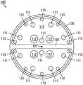
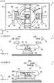
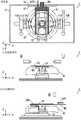
图1是本发明的第1实施方式的包含下表面刷及刷基座的刷单元的外观立体图。FIG. 1 is an external perspective view of a brush unit including a lower surface brush and a brush base according to the first embodiment of the present invention.
图2是图1的下表面刷的外观立体图。FIG. 2 is an external perspective view of the lower surface brush of FIG. 1 .
图3是图1的下表面刷的俯视图。FIG. 3 is a plan view of the lower surface brush of FIG. 1 .
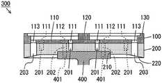
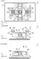
图4是图1的刷单元的纵剖视图。FIG. 4 is a vertical cross-sectional view of the brush unit of FIG. 1 .
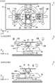
图5是用来说明刷单元的动作的图。FIG. 5 is a diagram for explaining the operation of the brush unit.
图6是变化例的下表面刷的外观立体图。FIG. 6 is an external perspective view of a lower surface brush of a modified example.
图7是参考例的下表面刷的外观立体图。7 is an external perspective view of a lower surface brush of a reference example.
图8是本发明的第2实施方式的下表面刷的外观立体图。8 is an external perspective view of a lower surface brush according to a second embodiment of the present invention.
图9是第1变化例的下表面刷的外观立体图。9 is an external perspective view of a lower surface brush of a first modification.
图10是第2变化例的下表面刷的外观立体图。10 is an external perspective view of a lower surface brush of a second modification.
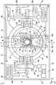
图11是本发明的第3实施方式的衬底清洗装置的示意性俯视图。11 is a schematic plan view of a substrate cleaning apparatus according to a third embodiment of the present invention.
图12是表示图11的衬底清洗装置的内部构成的外观立体图。FIG. 12 is an external perspective view showing the internal structure of the substrate cleaning apparatus of FIG. 11 .
图13是表示图11的衬底清洗装置的控制系统的构成的框图。FIG. 13 is a block diagram showing the configuration of a control system of the substrate cleaning apparatus of FIG. 11 .
图14是用来说明图11的衬底清洗装置的动作的一例的示意图。FIG. 14 is a schematic diagram for explaining an example of the operation of the substrate cleaning apparatus of FIG. 11 .
图15是用来说明图11的衬底清洗装置的动作的一例的示意图。FIG. 15 is a schematic diagram for explaining an example of the operation of the substrate cleaning apparatus of FIG. 11 .
图16是用来说明图11的衬底清洗装置的动作的一例的示意图。FIG. 16 is a schematic diagram for explaining an example of the operation of the substrate cleaning apparatus of FIG. 11 .
图17是用来说明图11的衬底清洗装置的动作的一例的示意图。FIG. 17 is a schematic diagram for explaining an example of the operation of the substrate cleaning apparatus of FIG. 11 .
图18是用来说明图11的衬底清洗装置的动作的一例的示意图。FIG. 18 is a schematic diagram for explaining an example of the operation of the substrate cleaning apparatus of FIG. 11 .
图19是用来说明图11的衬底清洗装置的动作的一例的示意图。FIG. 19 is a schematic diagram for explaining an example of the operation of the substrate cleaning apparatus of FIG. 11 .
图20是用来说明图11的衬底清洗装置的动作的一例的示意图。FIG. 20 is a schematic diagram for explaining an example of the operation of the substrate cleaning apparatus of FIG. 11 .
图21是用来说明图11的衬底清洗装置的动作的一例的示意图。FIG. 21 is a schematic diagram for explaining an example of the operation of the substrate cleaning apparatus of FIG. 11 .
图22是用来说明图11的衬底清洗装置的动作的一例的示意图。FIG. 22 is a schematic diagram for explaining an example of the operation of the substrate cleaning apparatus of FIG. 11 .
图23是用来说明图11的衬底清洗装置的动作的一例的示意图。FIG. 23 is a schematic diagram for explaining an example of the operation of the substrate cleaning apparatus of FIG. 11 .
图24是用来说明图11的衬底清洗装置的动作的一例的示意图。FIG. 24 is a schematic diagram for explaining an example of the operation of the substrate cleaning apparatus of FIG. 11 .
图25是用来说明图11的衬底清洗装置的动作的一例的示意图。FIG. 25 is a schematic diagram for explaining an example of the operation of the substrate cleaning apparatus of FIG. 11 .
具体实施方式Detailed ways
以下,针对本发明的实施方式的下表面刷、刷基座及衬底清洗装置,使用附图进行说明。以下的说明中,衬底是指半导体衬底、液晶显示装置或有机EL(ElectroLuminescence)显示装置等FPD(Flat Panel Display)用衬底、光盘用衬底、磁盘用衬底、磁光盘用衬底、光罩用衬底、陶瓷衬底或太阳能电池用衬底等。Hereinafter, the lower surface brush, the brush base, and the substrate cleaning apparatus according to the embodiment of the present invention will be described with reference to the drawings. In the following description, substrates refer to semiconductor substrates, substrates for FPD (Flat Panel Display) such as liquid crystal display devices or organic EL (ElectroLuminescence) display devices, substrates for optical disks, substrates for magnetic disks, and substrates for magneto-optical disks , Substrates for photomasks, ceramic substrates or substrates for solar cells, etc.
[1]第1实施方式[1] The first embodiment
(1)刷单元的构成(1) Composition of the brush unit
图1是本发明的第1实施方式的包含下表面刷及刷基座的刷单元的外观立体图。如图1所示,刷单元300通过在刷基座200上安装下表面刷100而构成。下表面刷100例如可由PVA(聚乙烯醇)或PTFE(聚四氟乙烯)等相对软质的树脂材料构成。刷基座200例如也可由PVC(聚氯乙烯)或PP(聚丙烯)等相对硬质的树脂构成。FIG. 1 is an external perspective view of a brush unit including a lower surface brush and a brush base according to the first embodiment of the present invention. As shown in FIG. 1 , the
图2是图1的下表面刷100的外观立体图。图3是图1的下表面刷100的俯视图。如图2及图3所示,下表面刷100包含基台部110及清洗部120、130。基台部110具有圆板形状。俯视时,定义基台部110的几何中心101(图3)。FIG. 2 is an external perspective view of the
清洗部120、清洗部130以从基台部110的上表面朝上方突出的方式,形成在基台部110的上表面。清洗部120以通过基台部110的几何中心101,在基台部110的径向延伸的方式配置。清洗部130以沿基台部110的外缘的方式配置。清洗部130可与清洗部120的两端接触。清洗部120、130相对于基台部110的上表面的突出量例如为5mm~6mm。清洗部120的宽度与清洗部130的宽度可相等,也可不等。The
在基台部110形成多个贯通孔111、多个贯通孔112及多个贯通孔113。各贯通孔111~113在上下方向延伸。贯通孔111用来连接基台部110与图1的刷基座200,本例中设置10个。具体来说,8个贯通孔111以大致等角度间隔配置在基台部110的周缘区域。2个贯通孔111以隔着清洗部120对向的方式配置在基台部110的中央区域。A plurality of through
贯通孔112用来连接刷基座200与使刷单元300旋转的马达等,本例中设置4个。4个贯通孔112以包围基台部110的几何中心101的方式,以大致等角度间隔配置在基台部110的中央区域。贯通孔113用来排出衬底清洗时的清洗液,本例中设置10个。10个贯通孔113以沿清洗部130的方式,沿基台部110的周缘区域规则配置。The through-
刷基座200是具有与下表面刷100的基台部110相同外形的板状部件。图4是图1的刷单元300的纵剖视图。如图4所示,在刷基座200的下表面的中央区域,形成朝下方凹陷的凹部210。此外,在刷基座200的下表面的周缘区域,形成朝外下方倾斜的倾斜部220。而且,在刷基座200,形成多个螺孔201、多个贯通孔202及多个贯通孔203。The
多个螺孔201以分别与下表面刷100的多个贯通孔111对应的方式,设置在刷基座200的上表面。多个贯通孔202以上下延伸且分别与下表面刷100的多个贯通孔112对应的方式配置。多个贯通孔203以上下延伸且分别与下表面刷100的多个贯通孔113对应的方式配置。The plurality of screw holes 201 are provided on the upper surface of the
多个螺纹部件310(图1)从上方分别插通下表面刷100的多个贯通孔111。各螺纹部件310的下端部与刷基座200中对应的螺孔201螺合。由此,将下表面刷100与刷基座200连接,刷单元300完成。刷单元300中,下表面刷100的多个贯通孔113分别与刷基座200的多个贯通孔203连通。The plurality of screw members 310 ( FIG. 1 ) are respectively inserted through the plurality of through
刷单元300安装在马达等的旋转轴400。具体来说,旋转轴400从下方嵌入刷基座200的凹部210。在旋转轴400,形成分别与刷基座200的贯通孔202对应的多个螺孔401。多个螺纹部件320(图1)从上方分别插通下表面刷100的多个贯通孔112。各螺纹部件320的下端部通过刷基座200中对应的贯通孔202,与旋转轴400中对应的螺孔401螺合。The
(2)刷单元的动作(2) Action of the brush unit
刷单元300可用来清洗衬底的下表面。以下,将衬底的下表面中的中央部分称为下表面中央区域。将衬底的下表面中包围下表面中央区域的区域称为下表面外侧区域。另外,衬底的下表面是指朝向下方的衬底的面。因此,衬底的电路形成面(正面)朝向下方的情况下,衬底的正面为下表面,在与正面为相反侧的面(背面)朝向下方的情况下,衬底的背面为下表面。The
图5是用来说明刷单元300的动作的图。清洗衬底W的下表面中央区域时,如图5的上层所示,刷单元300移动到衬底W的下表面中央区域的下方。接着,刷单元300的上端部与衬底W的下表面接触。之后,刷单元300绕通过基台部110的几何中心101的垂直轴旋转,由此将附着在衬底W的下表面中央区域的污染物去除。本例中,清洗衬底W的下表面中央区域时,衬底W未旋转,但衬底W也可旋转。FIG. 5 is a diagram for explaining the operation of the
清洗衬底W的下表面外侧区域时,如图5的下层所示,刷单元300移动到衬底W的下表面外侧区域的下方。此时,刷单元300的一部分也可比衬底W稍略朝外侧突出。接着,刷单元300的上端部与衬底W的下表面接触。之后,通过使衬底W旋转,将附着在衬底W的下表面外侧区域的污染物去除。本例中,清洗衬底W的下表面外侧区域时,刷单元300未旋转,但刷单元300也可旋转。When cleaning the outer region of the lower surface of the substrate W, the
本例中,下表面刷100的直径大于衬底W直径的1/3且小于1/2。所述情况下,通过使刷单元300在衬底W的下表面中央区域的下方与下表面外侧区域的下方之间移动,而效率良好地清洗衬底W的整个下表面。因此,无须过度增大下表面刷100。另外,衬底W的直径例如为300mm。如图5中一点划线所示,刷单元300移动到衬底W的下表面中央区域的下方时能清洗的区域,与刷单元300移动到衬底W的下表面外侧区域的下方时能清洗的区域可略微重叠。In this example, the diameter of the
清洗衬底W的下表面时,可对衬底W的下表面供给清洗液。所述情况下,能效率更好地去除附着在衬底W的下表面的污染物。供给到衬底W的下表面的清洗液通过形成在图4的下表面刷100的多个贯通孔113、及形成在刷基座200的多个贯通孔203,排出到刷基座200的下表面。因此,能够防止清洗液滞留在下表面刷100上。When cleaning the lower surface of the substrate W, a cleaning liquid may be supplied to the lower surface of the substrate W. In this case, the contaminants adhering to the lower surface of the substrate W can be removed more efficiently. The cleaning solution supplied to the lower surface of the substrate W passes through the plurality of through
此处,如图4所示,在刷基座200的下表面的周缘区域,形成朝外下方倾斜的倾斜部220。因此,排出到刷基座200的下表面的清洗液不会被引导到刷基座200的内侧,而会沿着倾斜部220被引导到外侧,从刷基座200排出。由此,防止清洗液附着在旋转轴400或马达等。Here, as shown in FIG. 4 , in the peripheral region of the lower surface of the
(3)变化例(3) Variation example
本实施方式中,俯视时下表面刷100的外形为圆形状,但实施方式不限定于此。俯视时下表面刷100的外形也可为其它形状。所述情况下,清洗部120以俯视时,在基台部110的外缘中离得最远的2点之间延伸的方式设置。由此,能将能清洗的区域维持得较大。以下,针对变化例的下表面刷100,说明与图2的下表面刷100不同的点。In this embodiment, the outer shape of the
图6是变化例的下表面刷100的外观立体图。如图6所示,变化例的下表面刷100中,基台部110具有长圆板形状。清洗部120以俯视时通过基台部110的几何中心101,且与基台部110的长边平行地延伸的方式配置。刷基座200与下表面刷100的基台部110同样,具有长圆形状的外形。所述例中,俯视时下表面刷100的外形为长圆形状。FIG. 6 is an external perspective view of the
或者,基台部110也可具有椭圆板形状。所述情况下,清洗部120以俯视时通过基台部110的几何中心101,且与基台部110的长径重合地延伸的方式配置。另外,俯视时基台部110的几何中心101为基台部110的长径与短径的交点。刷基座200与下表面刷100的基台部110同样,具有椭圆形状的外形。所述例中,俯视时下表面刷100的外形为椭圆形状。Alternatively, the
(4)效果(4) Effect
本实施方式的下表面刷100中,清洗部120以从基台部110的上表面朝上方突出,且俯视时通过基台部110的几何中心101在一个方向延伸的方式,设置在基台部110的上表面。此外,清洗部130以从基台部110的上表面朝上方突出,且沿基台部110的外缘的方式,设置在基台部110的上表面。In the
根据所述构成,能将能清洗的区域维持得较大,且减少衬底W的下表面与下表面刷100的接触面积。因此,即使施加在下表面刷100的荷重相对较小的情况下,衬底W的下表面与下表面刷100也以足够的荷重接触。由此,能效率良好地清洗衬底W的下表面。According to the above configuration, the washable area can be maintained large, and the contact area between the lower surface of the substrate W and the
(5)参考例(5) Reference example
图7是参考例的下表面刷的外观立体图。如图7所示,参考例的下表面刷100A除不包含清洗部130的方面及未在基台部110形成贯通孔113的方面外,具有与图6的变化例的下表面刷100相同的构成。此外,也可不在与下表面刷100A对应的刷基座,形成贯通孔203。7 is an external perspective view of a lower surface brush of a reference example. As shown in FIG. 7 , the
利用包含参考例的下表面刷100A的刷单元进行衬底W的下表面外侧区域清洗的情况下,优选为使刷单元旋转。或者,优选为通过编码器等检测下表面刷100A的方向。且,进行衬底W的下表面外侧区域清洗的情况下,优选为在衬底W的下表面外侧区域的下方,以清洗部120朝向与衬底W的外缘的切线正交的方向(法线方向)的方式,控制下表面刷100A的方向。When cleaning the outer region of the lower surface of the substrate W by a brush unit including the
[2]第2实施方式[2] Second Embodiment
(1)刷单元的构成(1) Composition of the brush unit
针对第2实施方式的下表面刷100及刷基座200,说明与第1实施方式的下表面刷100及刷基座200的不同点。图8是本发明的第2实施方式的下表面刷100的外观立体图。如图8所示,本实施方式中,下表面刷100包含以隔着清洗部120对向的方式配置的一对或多对清洗部140,来取代图1的清洗部130。About the
本例中,下表面刷100包含三对清洗部140。各清洗部140以从基台部110的外侧向基台部110的几何中心101延伸,且从基台部110的上表面朝上方突出的方式,形成在基台部110的上表面。清洗部140相对于基台部110的上表面的突出量例如为5mm~6mm。清洗部120的宽度与清洗部140的宽度可相等,也可不等。此外,各清洗部140的内端部也可与清洗部120接触。In this example, the
通过将图8的下表面刷100连接在图1的刷基座200,构成刷单元300。本实施方式的刷单元300的动作与第1实施方式的刷单元300的动作相同。The
衬底清洗时可使用清洗液的情况下,供给到衬底W的下表面的清洗液通过清洗部120、140之间,从基台部110的周缘排出到外侧。因此,防止清洗液滞留在下表面刷100上。因此,本实施方式中,也可不在下表面刷100的基台部110形成图4的贯通孔113。同样地,也可不在刷基座200形成图4的贯通孔203。然而,实施方式不限定于此,也可在下表面刷100的基台部110形成贯通孔113,也可在刷基座200形成贯通孔203。When a cleaning liquid can be used for cleaning the substrate, the cleaning liquid supplied to the lower surface of the substrate W passes between the cleaning
此外,进行衬底W的下表面外侧区域清洗的情况下,可使刷单元300旋转。或者,也可通过编码器等检测下表面刷100的方向。且,进行衬底W的下表面外侧区域清洗时,也可在衬底W的下表面外侧区域的下方,以清洗部120朝向与衬底W的外缘的切线正交的方向(法线方向)的方式,控制下表面刷100的方向。In addition, when cleaning the outer region of the lower surface of the substrate W, the
(2)变化例(2) Variation example
本实施方式中,各清洗部140从基台部110的外侧向基台部110的几何中心101延伸,但实施方式不限定于此。各清洗部140也可不从基台部110的外侧向基台部110的几何中心101延伸。此外,与第1实施方式的变化例同样,俯视时下表面刷100的外形也可为长圆形状或椭圆形状等其它形状。以下,针对变化例的下表面刷100,说明与图8的下表面刷100不同的点。In this embodiment, each cleaning
图9是第1变化例的下表面刷100的外观立体图。如图9所示,第1变化例的下表面刷100中,一部分清洗部140从基台部110的外侧弯折,且朝基台部110的几何中心101延伸。一部分清洗部140可从基台部110的外侧弯曲,且朝基台部110的几何中心101延伸。FIG. 9 is an external perspective view of the
图10是第2变化例的下表面刷100的外观立体图。如图10所示,第2变化例的下表面刷100包含一对清洗部140。此外,基台部110具有长圆板形状。清洗部120以俯视时通过基台部110的几何中心101且与基台部110的长边平行延伸的方式配置。一对清洗部140以分别沿基台部110的一对长边的方式配置。FIG. 10 is an external perspective view of the
(3)效果(3) Effect
本实施方式的下表面刷100中,清洗部120以从基台部110的上表面朝上方突出,且俯视时通过基台部110的几何中心101在一个方向延伸的方式,设置在基台部110的上表面。此外,一对或多对清洗部140以从基台部110的上表面朝上方突出,且隔着清洗部120对向的方式,设置在基台部110的上表面。In the
根据所述构成,能将能清洗的区域维持得较大,且减少衬底W的下表面与下表面刷100的接触面积。因此,即使施加在下表面刷100的荷重相对较小的情况下,衬底W的下表面与下表面刷100也以足够的荷重接触。由此,能效率良好地清洗衬底W的下表面。According to the above configuration, the washable area can be maintained large, and the contact area between the lower surface of the substrate W and the
[3]第3实施方式[3] Third Embodiment
(1)衬底清洗装置的构成(1) Configuration of the substrate cleaning device
作为第3实施方式,说明包含第1或第2实施方式的下表面刷100的衬底清洗装置的详细构成。图11是本发明的第3实施方式的衬底清洗装置的示意性俯视图。图12是表示图11的衬底清洗装置1的内部构成的外观立体图。本实施方式的衬底清洗装置1中,为明确位置关系,定义互相正交的X方向、Y方向及Z方向。在图11及图12之后的特定附图中,适当地以箭头表示X方向、Y方向及Z方向。X方向及Y方向在水平面内互相正交,Z方向相当于铅直方向。As the third embodiment, the detailed configuration of the substrate cleaning apparatus including the
如图11所示,衬底清洗装置1具备上侧保持装置10A、10B、下侧保持装置20、台座装置30、交接装置40、下表面清洗装置50、杯装置60、上表面清洗装置70、端部清洗装置80及开闭装置90。这些构成要件设置在单元外壳2内。图12中,单元外壳2以虚线表示。As shown in FIG. 11 , the
单元外壳2具有矩形的底面部2a、及从底面部2a的4条边朝上方延伸的4个侧壁部2b、2c、2d、2e。侧壁部2b、2c互相对向,侧壁部2d、2e互相对向。在侧壁部2b的中央部,形成着矩形开口。所述开口为衬底W的搬入搬出口2x,在对单元外壳2搬入及搬出衬底W时使用。图12中,搬入搬出口2x以粗虚线表示。以下的说明中,将Y方向中从单元外壳2的内部通过搬入搬出口2x朝向单元外壳2的外侧的方向(从侧壁部2c朝向侧壁部2b的方向)称为前方,将其相反方向(从侧壁部2b朝向侧壁部2c的方向)称为后方。The
在侧壁部2b中搬入搬出口2x的形成部分及其附近区域,设置着开闭装置90。开闭装置90包含能开闭搬入搬出口2x而构成的挡板91、及驱动挡板91的挡板驱动部92。图12中,挡板91以粗二点划线表示。挡板驱动部92以对衬底清洗装置1搬入及搬出衬底W时,打开搬入搬出口2x的方式驱动挡板91。此外,挡板驱动部92以衬底清洗装置1中衬底W的清洗处理时,关闭搬入搬出口2x的方式驱动挡板91。In the
在底面部2a的中央部,设置着台座装置30。台座装置30包含线性导件31、可动台座32及台座驱动部33。线性导件31包含2条导轨,以俯视时从侧壁部2b附近在Y方向延伸到侧壁部2c附近的方式设置。可动台座32设置成能在线性导件31的2条导轨上在Y方向移动。台座驱动部33包含例如脉冲马达,使可动台座32在线性导件31上在Y方向移动。In the center part of the
在可动台座32上,以在Y方向排列的方式设置着下侧保持装置20及下表面清洗装置50。下侧保持装置20包含吸附保持部21及吸附保持驱动部22。吸附保持部21是所谓的旋转夹盘,具有能吸附保持衬底W的下表面的圆形吸附面,构成为能绕在上下方向延伸的轴(Z方向的轴)旋转。图11中,由下侧保持装置20吸附保持的衬底W的外形以二点划线表示。On the
吸附保持驱动部22包含马达。吸附保持驱动部22的马达以旋转轴朝上方突出的方式,设置在可动台座32上。吸附保持部21安装在吸附保持驱动部22的旋转轴的上端部。此外,在吸附保持驱动部22的旋转轴,形成着吸附保持部21中用来吸附保持衬底W的吸引路径。所述吸引路径连接在未图示的吸气装置。吸附保持驱动部22使吸附保持部21绕所述旋转轴旋转。The suction-holding
在可动台座32上,在下侧保持装置20附近还设置着交接装置40。交接装置40包含多根(本例中为3根)支撑销41、销连结部件42及销升降驱动部43。销连结部件42以俯视时包围吸附保持部21的方式形成,连结多根支撑销41。多根支撑销41以由销连结部件42互相连结的状态,从销连结部件42朝上方延伸一定长度。销升降驱动部43使销连结部件42在可动台座32上升降。由此,多根支撑销41相对于吸附保持部21相对升降。On the
下表面清洗装置50包含刷单元300、2个液体喷嘴52、气体喷出部53、升降支撑部54、移动支撑部55、下表面刷旋转驱动部55a、下表面刷升降驱动部55b及下表面刷移动驱动部55c。移动支撑部55设置成在可动台座32上的一定区域内能相对于下侧保持装置20在Y方向移动。如图12所示,在移动支撑部55上,可升降地设置着升降支撑部54。升降支撑部54具有在远离吸附保持部21的方向(本例中为后方)朝斜下方倾斜的上表面54u。The lower
刷单元300包含第1或第2实施方式的下表面刷100与刷基座200。另外,刷单元300也可包含未在下表面形成倾斜部220(图4)的刷基座,来取代第1或第2实施方式的刷基座200。如图11所示,刷单元300以下表面刷100朝向上方,且能绕通过基台部110的几何中心101(图3)在上下方向延伸的轴旋转的方式,安装在升降支撑部54的上表面54u。下表面刷100的基台部110的面积大于吸附保持部21的吸附面的面积。The
2个液体喷嘴52分别位于刷单元300附近且以液体喷出口朝向上方的方式,安装在升降支撑部54的上表面54u上。在液体喷嘴52,连接着下表面清洗液供给部56(图13)。下表面清洗液供给部56对液体喷嘴52供给清洗液。液体喷嘴52在刷单元300清洗衬底W时,将从下表面清洗液供给部56供给的清洗液供给到衬底W的下表面。本实施方式中,可使用纯水(去离子水)作为供给到液体喷嘴52的清洗液。另外,作为供给到液体喷嘴52的清洗液,也可使用碳酸水、臭氧水、氢水、电解离子水、SC1(氨水与过氧化氢水的混合溶液)或TMAH(四甲基氢氧化铵)等来取代纯水。The two
气体喷出部53是具有在一个方向延伸的气体喷出口的缝隙状气体喷射喷嘴。气体喷出部53以俯视时位于刷单元300与吸附保持部21之间,且气体喷射口朝向上方的方式,安装在升降支撑部54的上表面54u。在气体喷出部53,连接着喷出气体供给部57(图13)。喷出气体供给部57对气体喷出部53供给气体。本实施方式中,可使用氮气作为供给到气体喷出部53的气体。气体喷出部53在由刷单元300清洗衬底W时及后述的衬底W的下表面的干燥时,将从喷出气体供给部57供给的气体喷射至衬底W的下表面。所述情况下,在刷单元300与吸附保持部21之间,形成在X方向延伸的带状的气帘。作为供给到气体喷出部53的气体,也可使用氩气或氦气等惰性气体来取代氮气。The
下表面刷旋转驱动部55a包含具有旋转轴400(图4)的马达,在由刷单元300清洗衬底W时,使刷单元300旋转。由此,能将刷单元300能清洗的区域维持得较大。The lower surface brush
下表面刷升降驱动部55b包含步进马达或气缸,使升降支撑部54相对于移动支撑部55升降。下表面刷移动驱动部55c包含马达,使移动支撑部55在可动台座32上在Y方向移动。此处,可动台座32中下侧保持装置20的位置固定。因此,利用下表面刷移动驱动部55c使移动支撑部55在Y方向移动时,移动支撑部55相对于下侧保持装置20相对移动。以下的说明中,将可动台座32上最接近下侧保持装置20时的下表面清洗装置50的位置称为接近位置,将可动台座32上离下侧保持装置20最远时的下表面清洗装置50的位置称为离开位置。The lower surface brush
在底面部2a的中央部,还设置着杯装置60。杯装置60包含杯61及杯驱动部62。杯61以俯视时包围下侧保持装置20及台座装置30的方式能升降地设置。图12中,杯61以虚线表示。杯驱动部62根据刷单元300要清洗衬底W的下表面中的哪个部分,使杯61在下杯位置与上杯位置之间移动。下杯位置为杯61的上端部位于比由吸附保持部21吸附保持的衬底W下方的高度位置。此外,上杯位置为杯61的上端部位于比吸附保持部21上方的高度位置。The
在比杯61上方的高度位置,以俯视时隔着台座装置30对向的方式,设置着一对上侧保持装置10A、10B。上侧保持装置10A包含下夹盘11A、上夹盘12A、下夹盘驱动部13A及上夹盘驱动部14A。上侧保持装置10B包含下夹盘11B、上夹盘12B、下夹盘驱动部13B及上夹盘驱动部14B。A pair of
下夹盘11A、11B相对于俯视时通过吸附保持部21的中心在Y方向(前后方向)延伸的铅直面对称配置,且设置成在共通的水平面内能在X方向移动。下夹盘11A、11B各自具有能从衬底W的下方支撑衬底W的下表面周缘部的2块支撑片。下夹盘驱动部13A、13B使下夹盘11A、11B以下夹盘11A、11B互相靠近的方式,或以下夹盘11A、11B互相远离的方式移动。The lower chucks 11A and 11B are arranged symmetrically with respect to a vertical plane extending in the Y direction (front-rear direction) through the center of the
上夹盘12A、12B与下夹盘11A、11B同样,相对于俯视时通过吸附保持部21的中心在Y方向(前后方向)延伸的铅直面对称配置,且设置成在共通的水平面内能在X方向移动。上夹盘12A、12B各自具有构成为与衬底W的外周端部的2个部分抵接,而能保持衬底W的外周端部的2块保持片。上夹盘驱动部14A、14B使上夹盘12A、12B以上夹盘12A、12B互相靠近的方式,或以上夹盘12A、12B互相远离的方式移动。The upper chucks 12A, 12B, like the
如图11所示,在杯61的一侧,以俯视时位于上侧保持装置10B附近的方式,设置着上表面清洗装置70。上表面清洗装置70包含旋转支撑轴71、臂72、喷雾喷嘴73及上表面清洗驱动部74。As shown in FIG. 11 , on one side of the
旋转支撑轴71以在上下方向延伸的方式,且能升降、能旋转地由上表面清洗驱动部74支撑在底面部2a上。臂72如图12所示,在比上侧保持装置10B上方的位置,以从旋转支撑轴71的上端部在水平方向延伸的方式设置。在臂72的前端部,安装着喷雾喷嘴73。The
在喷雾喷嘴73,连接上表面清洗流体供给部75(图13)。上表面清洗流体供给部75对喷雾喷嘴73供给清洗液及气体。本实施方式中,使用纯水作为供给到喷雾喷嘴73的清洗液,使用氮气作为供给到喷雾喷嘴73的气体。喷雾喷嘴73在清洗衬底W的上表面时,将从上表面清洗流体供给部75供给的清洗液与气体混合,产生混合流体,将产生的混合流体朝下方喷射。To the
另外,作为供给到喷雾喷嘴73的清洗液,也可使用碳酸水、臭氧水、氢水、电解离子水、SC1(氨水与过氧化氢水的混合溶液)或TMAH(四甲基氢氧化铵)等来取代纯水。此外,作为供给到喷雾喷嘴73的气体,也可使用氩气或氦气等惰性气体取代来氮气。In addition, carbonated water, ozone water, hydrogen water, electrolytic ionized water, SC1 (a mixed solution of ammonia water and hydrogen peroxide water), or TMAH (tetramethylammonium hydroxide) can also be used as the cleaning liquid to be supplied to the
上表面清洗驱动部74包含1个或多个脉冲马达及气缸等,使旋转支撑轴71升降,同时使旋转支撑轴71旋转。根据所述构成,通过在由吸附保持部21吸附保持并旋转的衬底W的上表面上,使喷雾喷嘴73圆弧状移动,能清洗衬底W的整个上表面。The upper surface cleaning
如图11所示,在杯61的另一侧,以俯视时位于上侧保持装置10A附近的方式,设置着端部清洗装置80。端部清洗装置80包含旋转支撑轴81、臂82、斜面刷83及斜面刷驱动部84。As shown in FIG. 11 , on the other side of the
旋转支撑轴81以在上下方向延伸的方式,且能升降、能旋转地由斜面刷驱动部84支撑在底面部2a上。臂82如图12所示,在比上侧保持装置10A上方的位置,以从旋转支撑轴81的上端部在水平方向延伸的方式设置。在臂82的前端部,以朝下方突出且能绕上下方向的轴旋转的方式,设置着斜面刷83。The
斜面刷83由例如PVA海绵或分散着研磨粒的PVA海绵形成,上半部具有倒圆锥梯形形状,同时下半部具有圆锥梯形形状。根据所述斜面刷83,能在外周面的上下方向的中央部分清洗衬底W的外周端部。The
斜面刷驱动部84包含1个或多个脉冲马达及气缸等,使旋转支撑轴81升降,同时使旋转支撑轴81旋转。根据所述构成,使斜面刷83的外周面的中央部分与由吸附保持部21吸附保持并旋转的衬底W的外周端部接触,由此能清洗衬底W的整个外周端部。The inclined surface
此处,斜面刷驱动部84还包含内置在臂82内的马达。所述马达使设置在臂82的前端部的斜面刷83绕上下方向的轴旋转。因此,在清洗衬底W的外周端部时,通过使斜面刷83旋转,提高衬底W的外周端部中斜面刷83的清洗力。Here, the slant
图13是表示图11的衬底清洗装置1的控制系统的构成的框图。图13的控制部9包含CPU(Central Processing Unit:中央运算处理装置)、RAM(Random Access Memory:随机存取存储器)及ROM(Read Only Memory:只读存储器)。RAM作为CPU的作业区域使用。ROM存储系统程序。存储装置存储控制程序。通过使CPU在RAM上执行存储在存储装置的衬底清洗程序,而控制衬底清洗装置1的各部的动作。FIG. 13 is a block diagram showing the configuration of a control system of the
如图13所示,控制部9为了接收搬入到衬底清洗装置1的衬底W,并在吸附保持部21的上方位置加以保持,主要控制下夹盘驱动部13A、13B及上夹盘驱动部14A、14B。此外,控制部9为了由吸附保持部21吸附保持衬底W,同时使吸附保持的衬底W旋转,主要控制吸附保持驱动部22。As shown in FIG. 13 , the control unit 9 mainly controls the lower
此外,控制部9为了使可动台座32相对于由上侧保持装置10A、10B保持的衬底W移动,主要控制台座驱动部33。此外,控制部9为了使衬底W在由上侧保持装置10A、10B保持的衬底W的高度位置、与由吸附保持部21保持的衬底W的高度位置之间移动,而控制销升降驱动部43。In addition, the control unit 9 mainly controls the
此外,控制部9为了清洗衬底W的下表面,而控制下表面刷旋转驱动部55a、下表面刷升降驱动部55b、下表面刷移动驱动部55c、下表面清洗液供给部56及喷出气体供给部57。此外,控制部9为了由杯61接住清洗由吸附保持部21吸附保持的衬底W时从衬底W飞散的清洗液,而控制杯驱动部62。In addition, in order to clean the lower surface of the substrate W, the control unit 9 controls the lower surface brush
此外,控制部9为了清洗由吸附保持部21吸附保持的衬底W的上表面,而控制上表面清洗驱动部74及上表面清洗流体供给部75。此外,控制部9为了清洗由吸附保持部21吸附保持的衬底W的外周端部,而控制斜面刷驱动部84。此外,控制部9为了在衬底清洗装置1中搬入及搬出衬底W时开闭单元外壳2的搬入搬出口2x,而控制挡板驱动部92。In addition, the control unit 9 controls the upper surface cleaning
(2)衬底清洗装置的动作(2) Operation of the substrate cleaning device
图14~图25是用来说明图11的衬底清洗装置1的动作的一例的示意图。图14~图25的各图中,上层表示衬底清洗装置1的俯视图。此外,中层表示沿Y方向观察的下侧保持装置20及其周边部的侧视图,下层表示沿X方向观察的下侧保持装置20及其周边部的侧视图。中层的侧视图与图11的A-A线侧视图对应,下层的侧视图与图11的B-B线侧视图对应。另外,为了容易理解衬底清洗装置1中各构成要件的形状及动作状态,上层的俯视图与中层及下层的侧视图之间,一部分构成要件的缩放比率不同。此外,图14~图25中,杯61以二点划线表示,同时衬底W的外形以粗一点划线表示。14 to 25 are schematic diagrams for explaining an example of the operation of the
在对衬底清洗装置1搬入衬底W前的初始状态下,开闭装置90的挡板91将搬入搬出口2x关闭。此外,如图11所示,下夹盘11A、11B维持下夹盘11A、11B之间的距离充分大于衬底W的直径的状态。此外,上夹盘12A、12B也维持上夹盘12A、12B之间的距离充分大于衬底W的直径的状态。此外,台座装置30的可动台座32以俯视时吸附保持部21的中心位于杯61的中心的方式配置。此外,在可动台座32上,下表面清洗装置50配置在接近位置。此外,下表面清洗装置50的升降支撑部54处于使刷单元300的上端部位于比吸附保持部21下方的位置的状态。此外,交接装置40处于使多个支撑销41位于比吸附保持部21下方的状态。此外,杯装置60中,杯61位于下杯位置。以下的说明中,将俯视时杯61的中心位置称为平面基准位置rp。此外,将俯视时吸附保持部21的中心位于平面基准位置rp时的底面部2a上的可动台座32的位置称为第1水平位置。In the initial state before the substrate W is loaded into the
对衬底清洗装置1的单元外壳2内搬入衬底W。具体来说,在即将搬入衬底W前,挡板91将搬入搬出口2x打开。之后,如图14中以粗实线箭头a1所示,未图示的衬底搬送机器人的机械手(衬底保持部)RH通过搬入搬出口2x,将衬底W搬入到单元外壳2内的大致中央位置。此时,由机械手RH保持的衬底W如图14所示,位于下夹盘11A及上夹盘12A与下夹盘11B及上夹盘12B之间。The substrate W is loaded into the
接着,如图15中以粗实线箭头a2所示,以下夹盘11A、11B的多个支撑片位于衬底W的下表面周缘部的下方的方式,使下夹盘11A、11B互相靠近。在所述状态下,使机械手RH下降,从搬入搬出口2x退出。由此,保持在机械手RH的衬底W的下表面周缘部的多个部分由下夹盘11A、11B的多块支撑片支撑。机械手RH退出后,挡板91将搬入搬出口2x关闭。15, the
接着,如图16中以粗实线箭头a3所示,以上夹盘12A、12B的多块保持片与衬底W的外周端部抵接的方式,使上夹盘12A、12B互相靠近。通过使上夹盘12A、12B的多块保持片与衬底W的外周端部的多个部分抵接,由下夹盘11A、11B支撑的衬底W还由上夹盘12A、12B保持。如此,由上侧保持装置10A、10B保持的衬底W的中心在俯视时与平面基准位置rp重合或几乎重合。此外,如图16中以粗实线箭头a4所示,以吸附保持部21与平面基准位置rp偏移特定距离,同时刷单元300的几何中心101(图3)位于平面基准位置rp的方式,使可动台座32从第1水平位置朝前方移动。此时,将位于底面部2a上的可动台座32的位置称为第2水平位置。16, the
接着,如图17中以粗实线箭头a5所示,以刷单元300与衬底W的下表面中央区域接触的方式,使升降支撑部54上升。此外,如图17中以粗实线箭头a6所示,使刷单元300绕上下方向的轴旋转(自转)。由此,附着在衬底W的下表面中央区域的污染物质通过刷单元300被物理性剥离。Next, as shown by the thick solid line arrow a5 in FIG. 17 , the
图17的下层,在对白框内表示刷单元300与衬底W的下表面接触部分的放大侧视图。如所述对白框内所示,在刷单元300与衬底W接触的状态下,液体喷嘴52及气体喷出部53保持在接近衬底W的下表面的位置。此时,液体喷嘴52如白色箭头a51所示,在刷单元300附近的位置朝衬底W的下表面喷出清洗液。由此,通过将从液体喷嘴52供给到衬底W的下表面的清洗液引导到刷单元300与衬底W的接触部,而由清洗液冲洗由刷单元300从衬底W的下表面去除的污染物质。如此,下表面清洗装置50中,液体喷嘴52与刷单元300一起安装在升降支撑部54。由此,可对衬底W的下表面中由刷单元300清洗部分效率良好地供给清洗液。因此,减少清洗液的消耗量,同时抑制清洗液的过度飞散。The lower layer of FIG. 17 shows an enlarged side view of the contact portion of the
另外,清洗衬底W的下表面时的刷单元300的旋转速度维持为从液体喷嘴52供给到衬底W的下表面的清洗液不会飞散到刷单元300的侧方的程度的速度。In addition, the rotational speed of the
此处,升降支撑部54的上表面54u在远离吸附保持部21的方向上朝斜下方倾斜。所述情况下,含有污染物质的清洗液从衬底W的下表面落下到升降支撑部54上的情况下,将由上表面54u接住的清洗液朝远离吸附保持部21的方向引导。Here, the
此外,由刷单元300清洗衬底W的下表面时,气体喷出部53如图17的对白框内的白色箭头a52所示,在刷单元300与吸附保持部21之间的位置,朝衬底W的下表面喷射气体。本实施方式中,气体喷出部53以气体喷射口在X方向延伸的方式,安装在升降支撑部54上。所述情况下,从气体喷出部53对衬底W的下表面喷射气体时,在刷单元300与吸附保持部21之间,形成在X方向延伸的带状气帘。由此,防止由刷单元300清洗衬底W的下表面时,含有污染物质的清洗液朝吸附保持部21飞散。因此,防止由刷单元300清洗衬底W的下表面时,含有污染物质的清洗液附着在吸附保持部21,而将吸附保持部21的吸附面保持清洁。In addition, when the lower surface of the substrate W is cleaned by the
另外,图17的例子中,气体喷出部53如白色箭头a52所示,从气体喷出部53朝刷单元300朝斜上方喷射气体,但本发明不限定于此。气体喷出部53也可以从气体喷出部53朝衬底W的下表面沿Z方向的方式喷射气体。In addition, in the example of FIG. 17, the
接着,在图17的状态下,当衬底W的下表面中央区域的清洗完成时,停止刷单元300的旋转,以刷单元300的上端部与衬底W离开特定距离的方式,使升降支撑部54下降。此外,停止从液体喷嘴52朝衬底W喷出清洗液。此时,继续从气体喷出部53朝衬底W喷射气体。Next, in the state of FIG. 17 , when the cleaning of the central region of the lower surface of the substrate W is completed, the rotation of the
之后,如图18中以粗实线箭头a7所示,以吸附保持部21位于平面基准位置rp的方式,使可动台座32朝后方移动。也就是说,可动台座32从第2水平位置移动到第1水平位置。此时,通过继续从气体喷出部53对衬底W喷射气体,而由气帘将衬底W的下表面中央区域依序干燥。After that, as shown by the thick solid line arrow a7 in FIG. 18 , the movable table 32 is moved rearward so that the
接着,如图19中以粗实线箭头a8所示,以刷单元300位于比吸附保持部21的吸附面(上端部)下方的方式,使升降支撑部54下降。此外,如图19中以粗实线箭头a9所示,以上夹盘12A、12B的多块保持片从衬底W的外周端部离开的方式,使上夹盘12A、12B互相远离。此时,衬底W成为由下夹盘11A、11B支撑的状态。Next, as shown by the thick solid line arrow a8 in FIG. 19 , the lifting
之后,如图19中粗实线箭头a10所示,以多根支撑销41的上端部位于比下夹盘11A、11B略上方的方式,使销连结部件42上升。由此,由下夹盘11A、11B支撑的衬底W由多个支撑销41接收。After that, as shown by the thick solid arrow a10 in FIG. 19 , the
接着,如图20中以粗实线箭头a11所示,使下夹盘11A、11B互相远离。此时,下夹盘11A、11B移动到俯视时不与由多个支撑销41支撑的衬底W重合的位置。由此,上侧保持装置10A、10B均返回到初始状态。Next, as shown by the thick solid arrow a11 in FIG. 20 , the
接着,如图21中以粗实线箭头a12所示,以多根支撑销41的上端部位于比吸附保持部21下方的方式,使销连结部件42下降。由此,支撑在多个支撑销41上的衬底W由吸附保持部21接收。在所述状态下,吸附保持部21吸附保持衬底W的下表面中央区域。如此,由下侧保持装置20吸附保持的衬底W的中心在俯视时与平面基准位置rp重合或几乎重合。与销连结部件42下降的同时或在销连结部件42的下降完成后,如图21中粗实线箭头a13所示,使杯61从下杯位置上升到上杯位置。Next, as shown by the thick solid arrow a12 in FIG. 21 , the
接着,如图22中以粗实线箭头a14所示,吸附保持部21绕上下方向的轴(吸附保持驱动部22的旋转轴的轴心)旋转。由此,吸附保持在吸附保持部21的衬底W以水平姿势旋转。Next, as shown by the thick solid line arrow a14 in FIG. 22 , the suction-holding
接着,使上表面清洗装置70的旋转支撑轴71旋转、下降。由此,如图22中以粗实线箭头a15所示,使喷雾喷嘴73移动到衬底W上方的位置,并以喷雾喷嘴73与衬底W之间的距离成为预先确定的距离的方式下降。在所述状态下,喷雾喷嘴73对衬底W的上表面喷射清洗液与气体的混合流体。此外,使旋转支撑轴71旋转。由此,如图22中以粗实线箭头a16所示,喷雾喷嘴73在旋转的衬底W上方的位置移动。通过对衬底W的整个上表面喷射混合流体,而清洗衬底W的整个上表面。Next, the
此外,由喷雾喷嘴73清洗衬底W的上表面时,端部清洗装置80的旋转支撑部81也旋转、下降。由此,如图22中以粗实线箭头a17所示,使斜面刷83移动到衬底W的外周端部上方的位置。此外,以斜面刷83的外周面的中央部分与衬底W的外周端部接触的方式下降。在所述状态下,使斜面刷83绕上下方向的轴旋转(自转)。由此,附着在衬底W的外周端部的污染物质通过斜面刷83而被物理性剥离。从衬底W的外周端部剥离的污染物质由从喷雾喷嘴73喷射到衬底W的混合流体的清洗液冲洗。In addition, when the upper surface of the substrate W is cleaned by the
此外,由喷雾喷嘴73清洗衬底W的上表面时,以刷单元300与衬底W的下表面外侧区域接触的方式,使升降支撑部54上升。此外,如图22中以粗实线箭头a18所示,刷单元300可绕上下方向的轴旋转(自转)。此外,液体喷嘴52朝衬底W的下表面喷出清洗液,气体喷出部53朝衬底W的下表面喷射气体。在所述状态下,如图22中粗实线箭头a19所示,进一步使移动支撑部55在可动台座32上,在接近位置与离开位置之间进行进退动作。由此,由刷单元300遍及由吸附保持部21吸附保持并旋转的衬底W的整个下表面外侧区域进行清洗。In addition, when the upper surface of the substrate W is cleaned by the
接着,当衬底W的上表面、外周端部及下表面外侧区域的清洗完成时,停止从喷雾喷嘴73对衬底W喷射混合流体。此外,如图23中以粗实线箭头a20所示,喷雾喷嘴73移动到杯61的一侧位置(初始状态的位置)。此外,如图23中以粗实线箭头a21所示,斜面刷83移动到杯61的另一侧位置(初始状态的位置)。而且,停止刷单元300的旋转,以刷单元300的上端部与衬底W离开特定距离的方式,使升降支撑部54下降。此外,停止从液体喷嘴52对衬底W喷出清洗液、及从气体喷出部53对衬底W喷射气体。在所述状态下,吸附保持部21高速旋转,由此甩掉附着在衬底W的清洗液,而将整个衬底W干燥。Next, when the cleaning of the upper surface, the outer peripheral end portion, and the outer region of the lower surface of the substrate W is completed, the spraying of the mixed fluid from the
接着,如图24中以粗实线箭头a22所示,使杯61从上杯位置下降到下杯位置。此外,以备将新的衬底W搬入到单元外壳2内,如图24中以粗实线箭头a23所示,使下夹盘11A、11B互相靠近到能支撑新的衬底W的位置。Next, the
最后,将衬底W从衬底清洗装置1的单元外壳2内搬出。具体来说,在即将搬出衬底W之前,挡板91打开搬入搬出口2x。之后,如图25中以粗实线箭头a24所示,未图示的衬底搬送机械人的机械手(衬底保持部)RH通过搬入搬出口2x进入单元外壳2内。接着,机械手RH接收吸附保持部21上的衬底W,从搬入搬出口2x退出。机械手RH退出后,挡板91将搬入搬出口2x关闭。Finally, the substrate W is carried out from the inside of the
(3)效果(3) Effect
本实施方式的衬底清洗装置1中,由上侧保持装置10A、10B或下侧保持装置20保持的衬底W的下表面由第1或第2实施方式的下表面刷100清洗。此处,清洗衬底W的下表面外侧区域时及清洗下表面中央区域时,下表面刷100分别移动到第1及第2水平位置。清洗衬底W的下表面外侧区域时,使衬底W旋转。由此,能将衬底W的整个下表面效率良好地清洗。In the
[4]技术方案的各构成要件与实施方式的各部的对应关系[4] Correspondence between each component of the technical solution and each part of the embodiment
以下,针对技术方案的各构成要件与实施方式的各构成要件的对应例进行说明,但本发明不限定于下述例。作为技术方案的各构成要件,也可使用具有技术方案所记载的构成或功能的其它各种要件。Hereinafter, the correspondence example of each component of the claim and each component of the embodiment will be described, but the present invention is not limited to the following examples. As each constituent element of the claim, other various requirements having the structure or function described in the claim can also be used.
所述实施方式中,衬底W为衬底的例子,下表面刷100为下表面刷的例子,基台部110为基台部的例子,几何中心101为几何中心的例子。清洗部120为第1清洗部的例子,清洗部130或清洗部140为第2清洗部的例子,贯通孔113为贯通孔的例子,倾斜部220为倾斜部的例子,刷基座200为刷基座的例子。上侧保持装置10A、10B或下侧保持装置20为衬底保持部的例子,衬底清洗装置1为衬底清洗装置的例子,台座驱动部33为移动装置的例子,下表面刷旋转驱动部55a为旋转驱动装置的例子。In the above embodiment, the substrate W is an example of a substrate, the
Claims (11)
Applications Claiming Priority (2)
| Application Number | Priority Date | Filing Date | Title |
|---|---|---|---|
| JP2020-196045 | 2020-11-26 | ||
| JP2020196045AJP7564693B2 (en) | 2020-11-26 | 2020-11-26 | Underside brush, brush unit and substrate cleaning device |
Publications (1)
| Publication Number | Publication Date |
|---|---|
| CN114551291Atrue CN114551291A (en) | 2022-05-27 |
Family
ID=81658887
Family Applications (1)
| Application Number | Title | Priority Date | Filing Date |
|---|---|---|---|
| CN202111409730.3APendingCN114551291A (en) | 2020-11-26 | 2021-11-25 | Lower surface brush, brush base and substrate cleaning device |
Country Status (5)
| Country | Link |
|---|---|
| US (1) | US12011743B2 (en) |
| JP (1) | JP7564693B2 (en) |
| KR (1) | KR102629947B1 (en) |
| CN (1) | CN114551291A (en) |
| TW (1) | TWI823167B (en) |
Cited By (1)
| Publication number | Priority date | Publication date | Assignee | Title |
|---|---|---|---|---|
| CN117772650A (en)* | 2022-09-26 | 2024-03-29 | 株式会社斯库林集团 | Substrate cleaning brush and substrate cleaning device |
Families Citing this family (3)
| Publication number | Priority date | Publication date | Assignee | Title |
|---|---|---|---|---|
| JP2024044925A (en)* | 2022-09-21 | 2024-04-02 | 株式会社Screenホールディングス | Lower surface brush, brush unit, and substrate cleaning device |
| JP2024044905A (en)* | 2022-09-21 | 2024-04-02 | 株式会社Screenホールディングス | Substrate cleaning apparatus and substrate cleaning method |
| CN118209713A (en)* | 2024-03-25 | 2024-06-18 | 中铁二十三局集团第一工程有限公司 | A feasibility determination method for using tunnel waste as aggregate for water-stabilized materials |
Citations (6)
| Publication number | Priority date | Publication date | Assignee | Title |
|---|---|---|---|---|
| JP2001104893A (en)* | 1994-06-03 | 2001-04-17 | Dainippon Screen Mfg Co Ltd | Brush and device and method for treating substrate |
| JP2009231628A (en)* | 2008-03-24 | 2009-10-08 | Dainippon Screen Mfg Co Ltd | Substrate processing apparatus |
| KR20120007452A (en)* | 2010-07-14 | 2012-01-20 | 도쿄엘렉트론가부시키가이샤 | Substrate cleaning apparatus, coating developing apparatus and substrate cleaning method comprising the same |
| TW201608663A (en)* | 2014-08-26 | 2016-03-01 | 荏原製作所股份有限公司 | Substrate processing device |
| JP2019145687A (en)* | 2018-02-21 | 2019-08-29 | 東京エレクトロン株式会社 | Cleaning tool, substrate cleaning device, and substrate cleaning method |
| JP2020155617A (en)* | 2019-03-20 | 2020-09-24 | 株式会社Screenホールディングス | Cleaning head, center brush, outer peripheral brush, substrate cleaning apparatus, and substrate cleaning method |
Family Cites Families (8)
| Publication number | Priority date | Publication date | Assignee | Title |
|---|---|---|---|---|
| JP4359906B2 (en) | 1999-04-28 | 2009-11-11 | アイオン株式会社 | Rotating brush for cleaning |
| JP5058085B2 (en) | 2008-07-02 | 2012-10-24 | 東京エレクトロン株式会社 | Substrate cleaning device |
| KR101022782B1 (en) | 2009-04-30 | 2011-03-17 | 세메스 주식회사 | Glass substrate cleaning unit and glass substrate cleaning system having the same |
| JP6001896B2 (en) | 2012-03-27 | 2016-10-05 | 株式会社Screenセミコンダクターソリューションズ | Substrate cleaning apparatus and substrate processing apparatus having the same |
| JP6210935B2 (en) | 2013-11-13 | 2017-10-11 | 東京エレクトロン株式会社 | Polishing and cleaning mechanism, substrate processing apparatus, and substrate processing method |
| JP6316730B2 (en) | 2014-10-31 | 2018-04-25 | 株式会社荏原製作所 | A substrate processing apparatus including a roll member, a pencil member, and at least one of them |
| US10276365B2 (en) | 2016-02-01 | 2019-04-30 | SCREEN Holdings Co., Ltd. | Substrate cleaning device, substrate processing apparatus, substrate cleaning method and substrate processing method |
| JP6726575B2 (en) | 2016-02-01 | 2020-07-22 | 株式会社Screenホールディングス | Substrate cleaning apparatus, substrate processing apparatus, substrate cleaning method and substrate processing method |
- 2020
- 2020-11-26JPJP2020196045Apatent/JP7564693B2/enactiveActive
- 2021
- 2021-10-29TWTW110140340Apatent/TWI823167B/enactive
- 2021-11-15USUS17/526,026patent/US12011743B2/enactiveActive
- 2021-11-25CNCN202111409730.3Apatent/CN114551291A/enactivePending
- 2021-11-26KRKR1020210165609Apatent/KR102629947B1/enactiveActive
Patent Citations (6)
| Publication number | Priority date | Publication date | Assignee | Title |
|---|---|---|---|---|
| JP2001104893A (en)* | 1994-06-03 | 2001-04-17 | Dainippon Screen Mfg Co Ltd | Brush and device and method for treating substrate |
| JP2009231628A (en)* | 2008-03-24 | 2009-10-08 | Dainippon Screen Mfg Co Ltd | Substrate processing apparatus |
| KR20120007452A (en)* | 2010-07-14 | 2012-01-20 | 도쿄엘렉트론가부시키가이샤 | Substrate cleaning apparatus, coating developing apparatus and substrate cleaning method comprising the same |
| TW201608663A (en)* | 2014-08-26 | 2016-03-01 | 荏原製作所股份有限公司 | Substrate processing device |
| JP2019145687A (en)* | 2018-02-21 | 2019-08-29 | 東京エレクトロン株式会社 | Cleaning tool, substrate cleaning device, and substrate cleaning method |
| JP2020155617A (en)* | 2019-03-20 | 2020-09-24 | 株式会社Screenホールディングス | Cleaning head, center brush, outer peripheral brush, substrate cleaning apparatus, and substrate cleaning method |
Cited By (1)
| Publication number | Priority date | Publication date | Assignee | Title |
|---|---|---|---|---|
| CN117772650A (en)* | 2022-09-26 | 2024-03-29 | 株式会社斯库林集团 | Substrate cleaning brush and substrate cleaning device |
Also Published As
| Publication number | Publication date |
|---|---|
| JP2022084287A (en) | 2022-06-07 |
| TW202221767A (en) | 2022-06-01 |
| KR102629947B1 (en) | 2024-01-29 |
| TWI823167B (en) | 2023-11-21 |
| US12011743B2 (en) | 2024-06-18 |
| US20220161299A1 (en) | 2022-05-26 |
| JP7564693B2 (en) | 2024-10-09 |
| KR20220073690A (en) | 2022-06-03 |
Similar Documents
| Publication | Publication Date | Title |
|---|---|---|
| CN114551291A (en) | Lower surface brush, brush base and substrate cleaning device | |
| KR102667272B1 (en) | Substrate cleaning device and substrate cleaning method | |
| TWI850692B (en) | Substrate cleaning device | |
| KR102678565B1 (en) | Substrate cleaning device and substrate cleaning method | |
| KR102636436B1 (en) | Substrate cleaning device | |
| KR102853110B1 (en) | Lower-surface brush, brush unit and substrate cleaning device | |
| KR102667273B1 (en) | Substrate cleaning device and substrate cleaning method | |
| TWI854793B (en) | Substrate cleaning brush and substrate cleaning device | |
| JP7491805B2 (en) | Substrate cleaning apparatus and substrate cleaning method | |
| JP7672908B2 (en) | Substrate cleaning apparatus and substrate cleaning method | |
| TWI808813B (en) | Substrate cleaning device, substrate cleaning system, substrate processing system, substrate cleaning method and substrate processing method |
Legal Events
| Date | Code | Title | Description |
|---|---|---|---|
| PB01 | Publication | ||
| PB01 | Publication | ||
| SE01 | Entry into force of request for substantive examination | ||
| SE01 | Entry into force of request for substantive examination |