CN114538065A - Soak circuit board transfer device - Google Patents
Soak circuit board transfer deviceDownload PDFInfo
- Publication number
- CN114538065A CN114538065ACN202210437879.0ACN202210437879ACN114538065ACN 114538065 ACN114538065 ACN 114538065ACN 202210437879 ACN202210437879 ACN 202210437879ACN 114538065 ACN114538065 ACN 114538065A
- Authority
- CN
- China
- Prior art keywords
- plate
- circuit board
- moving
- rod
- clamping
- Prior art date
- Legal status (The legal status is an assumption and is not a legal conclusion. Google has not performed a legal analysis and makes no representation as to the accuracy of the status listed.)
- Granted
Links
Images


Classifications
- B—PERFORMING OPERATIONS; TRANSPORTING
- B65—CONVEYING; PACKING; STORING; HANDLING THIN OR FILAMENTARY MATERIAL
- B65G—TRANSPORT OR STORAGE DEVICES, e.g. CONVEYORS FOR LOADING OR TIPPING, SHOP CONVEYOR SYSTEMS OR PNEUMATIC TUBE CONVEYORS
- B65G47/00—Article or material-handling devices associated with conveyors; Methods employing such devices
- B65G47/74—Feeding, transfer, or discharging devices of particular kinds or types
- B65G47/82—Rotary or reciprocating members for direct action on articles or materials, e.g. pushers, rakes, shovels
- B—PERFORMING OPERATIONS; TRANSPORTING
- B65—CONVEYING; PACKING; STORING; HANDLING THIN OR FILAMENTARY MATERIAL
- B65G—TRANSPORT OR STORAGE DEVICES, e.g. CONVEYORS FOR LOADING OR TIPPING, SHOP CONVEYOR SYSTEMS OR PNEUMATIC TUBE CONVEYORS
- B65G35/00—Mechanical conveyors not otherwise provided for
- B—PERFORMING OPERATIONS; TRANSPORTING
- B65—CONVEYING; PACKING; STORING; HANDLING THIN OR FILAMENTARY MATERIAL
- B65G—TRANSPORT OR STORAGE DEVICES, e.g. CONVEYORS FOR LOADING OR TIPPING, SHOP CONVEYOR SYSTEMS OR PNEUMATIC TUBE CONVEYORS
- B65G47/00—Article or material-handling devices associated with conveyors; Methods employing such devices
- B65G47/22—Devices influencing the relative position or the attitude of articles during transit by conveyors
- B—PERFORMING OPERATIONS; TRANSPORTING
- B65—CONVEYING; PACKING; STORING; HANDLING THIN OR FILAMENTARY MATERIAL
- B65G—TRANSPORT OR STORAGE DEVICES, e.g. CONVEYORS FOR LOADING OR TIPPING, SHOP CONVEYOR SYSTEMS OR PNEUMATIC TUBE CONVEYORS
- B65G47/00—Article or material-handling devices associated with conveyors; Methods employing such devices
- B65G47/74—Feeding, transfer, or discharging devices of particular kinds or types
- B65G47/90—Devices for picking-up and depositing articles or materials
- B65G47/902—Devices for picking-up and depositing articles or materials provided with drive systems incorporating rotary and rectilinear movements
- B—PERFORMING OPERATIONS; TRANSPORTING
- B65—CONVEYING; PACKING; STORING; HANDLING THIN OR FILAMENTARY MATERIAL
- B65G—TRANSPORT OR STORAGE DEVICES, e.g. CONVEYORS FOR LOADING OR TIPPING, SHOP CONVEYOR SYSTEMS OR PNEUMATIC TUBE CONVEYORS
- B65G59/00—De-stacking of articles
- B65G59/02—De-stacking from the top of the stack
- H—ELECTRICITY
- H05—ELECTRIC TECHNIQUES NOT OTHERWISE PROVIDED FOR
- H05K—PRINTED CIRCUITS; CASINGS OR CONSTRUCTIONAL DETAILS OF ELECTRIC APPARATUS; MANUFACTURE OF ASSEMBLAGES OF ELECTRICAL COMPONENTS
- H05K3/00—Apparatus or processes for manufacturing printed circuits
- B—PERFORMING OPERATIONS; TRANSPORTING
- B65—CONVEYING; PACKING; STORING; HANDLING THIN OR FILAMENTARY MATERIAL
- B65G—TRANSPORT OR STORAGE DEVICES, e.g. CONVEYORS FOR LOADING OR TIPPING, SHOP CONVEYOR SYSTEMS OR PNEUMATIC TUBE CONVEYORS
- B65G2201/00—Indexing codes relating to handling devices, e.g. conveyors, characterised by the type of product or load being conveyed or handled
- B65G2201/02—Articles
- B65G2201/0214—Articles of special size, shape or weigh
- B65G2201/022—Flat
Landscapes
- Engineering & Computer Science (AREA)
- Mechanical Engineering (AREA)
- Manufacturing & Machinery (AREA)
- Microelectronics & Electronic Packaging (AREA)
- Supply And Installment Of Electrical Components (AREA)
Abstract
Translated fromChinese
Description
Translated fromChinese技术领域technical field
本发明涉及电路板生产加工设备技术领域,尤其与一种浸泡电路板转移装置相关。The invention relates to the technical field of circuit board production and processing equipment, in particular to an immersed circuit board transfer device.
背景技术Background technique
在印制电路板结构中,金属化孔连接不同线路层,具有举足轻重的作用。因此,孔金属化加工步骤在印制电路板制作流程中具有很重要的地位,孔金属化有沉铜和整板电镀两个过程。在印制电路板经过沉铜和整板电镀工艺处理之后,需要将印制电路板浸泡在柠檬酸水溶液中转运至烘干线烘干,以避免铜层氧化影响孔金属化质量。现有技术中,由于电路板都泡在转运车的水中,相邻两个电路板之间互相吸附在一起,所以都采用人工的方式将转运车中的电路板转移至传送带上,这也就导致会耗费更多的人力,且生产线的自动化程度不高,同时转运车的水具有一定的酸性,工人长期抓板会影响工人的健康。In the printed circuit board structure, metallized holes play a pivotal role in connecting different circuit layers. Therefore, the hole metallization processing step has a very important position in the printed circuit board manufacturing process, and the hole metallization has two processes: copper sinking and whole board electroplating. After the printed circuit board is processed by the copper sinking and the whole board electroplating process, the printed circuit board needs to be immersed in a citric acid aqueous solution and transported to the drying line for drying to avoid the oxidation of the copper layer affecting the quality of the hole metallization. In the prior art, since the circuit boards are all soaked in the water of the transfer vehicle, and two adjacent circuit boards are adsorbed to each other, the circuit boards in the transfer vehicle are manually transferred to the conveyor belt. As a result, it will consume more manpower, and the automation degree of the production line is not high. At the same time, the water in the transfer vehicle has a certain degree of acidity, and the workers' long-term grasping of the board will affect the workers' health.
发明内容SUMMARY OF THE INVENTION
针对上述相关现有技术的不足,本申请提供一种浸泡电路板转移装置,能够自动将转运车中的电路板转移输送至传送带上,提高生产线的自动化程度,进而避免工作人员直接与浸泡在水中的电路板接触,保护工作人员健康,具有较强的实用性。In view of the above-mentioned deficiencies in the related art, the present application provides an immersed circuit board transfer device, which can automatically transfer and transport the circuit boards in the transfer vehicle to the conveyor belt, thereby improving the automation degree of the production line, thereby avoiding the direct contact between the staff and the immersion in water. Contact with the circuit board, protect the health of the staff, and have strong practicability.
为了实现上述目的,本发明采用以下技术:In order to achieve the above object, the present invention adopts the following technology:
一种浸泡电路板转移装置,包括:支撑架、夹持机构、转移机构、推送机构。A soaking circuit board transfer device, comprising: a support frame, a clamping mechanism, a transfer mechanism, and a push mechanism.
支撑架有两个并对称布置于传送带的一端,支撑架靠近传送带的一端设有横板,支撑架内侧沿其长度方向设有支撑板,支撑板上设有多个间隔均匀的滚轮,并通过驱动源提供动力;夹持机构设于支撑架远离传送带的一端,包括两个安装于支撑架上的弧形轨道,两个弧形轨道之间设有沿其轨迹移动的直线机构,直线机构的移动端上设有两个对称布置且运动方向相反的夹持组件,用于夹持电路板;转移机构包括设于滚轮上的承载板和两个竖直移动机构,承载板用于承载夹持机构夹持的电路板,竖直移动机构设于支撑架外侧,用于将承载板升起或降落;推送机构设于支撑架上方,用于将承载板上的电路板推出。There are two support frames and are symmetrically arranged at one end of the conveyor belt. The end of the support frame close to the conveyor belt is provided with a horizontal plate. The inner side of the support frame is provided with a support plate along its length direction. The driving source provides power; the clamping mechanism is arranged at one end of the support frame away from the conveyor belt, including two arc-shaped rails installed on the support frame, and a linear mechanism moving along the trajectory is arranged between the two arc-shaped rails. The moving end is provided with two clamping components arranged symmetrically and moving in opposite directions for clamping the circuit board; the transfer mechanism includes a bearing plate arranged on the roller and two vertical moving mechanisms, the bearing plate is used for bearing and clamping For the circuit board clamped by the mechanism, the vertical moving mechanism is arranged on the outside of the support frame, which is used to raise or lower the bearing board; the push mechanism is arranged above the support frame, and is used to push out the circuit board on the bearing board.
进一步地,横板远离传送带的一侧设有第一挡板,横板顶面设有第一凹部,第一挡板侧面设有两个水平布置的第一滑槽,第一滑槽内设有滑块,滑块一端设有插销,插销穿过第一凹部,第一凹部的底部一侧还设有向上倾斜的斜槽,斜槽用于穿过插销,且斜槽沿其轨迹方向设有多个限位槽,限位槽用于承载插销。Further, the side of the horizontal plate away from the conveyor belt is provided with a first baffle, the top surface of the horizontal plate is provided with a first concave portion, the side of the first baffle is provided with two horizontally arranged first chute, and the first chute is provided with a first chute. There is a slider, one end of the slider is provided with a latch, the latch passes through the first concave portion, and the bottom side of the first concave portion is also provided with an upwardly inclined oblique groove, the oblique groove is used to pass through the latch, and the oblique groove is arranged along its track direction. There are multiple limit slots, and the limit slots are used to carry the pins.
进一步地,夹持组件包括夹持框,夹持框呈U形,夹持框上端连接于连板上,连板套设于直线机构的移动端上,连板侧面在竖直方向设有两个支板,其中位于上方的支板设有双头伸缩杆,双头伸缩杆的移动端设有移动框,其中位于下方的支板两侧设有导杆,移动框上端穿设于导杆上,导杆一端设有挡块,挡块用于抵接到移动框;移动框侧面设有多个挡杆,夹持框内侧设有多个凹槽,挡杆穿设于凹槽中。Further, the clamping assembly includes a clamping frame, the clamping frame is U-shaped, the upper end of the clamping frame is connected to the connecting plate, the connecting plate is sleeved on the moving end of the linear mechanism, and the side of the connecting plate is provided with two vertical A support plate, wherein the upper support plate is provided with a double-ended telescopic rod, the moving end of the double-ended telescopic rod is provided with a moving frame, and the two sides of the support plate located at the bottom are provided with guide rods, and the upper end of the moving frame is penetrated through the guide rod One end of the guide rod is provided with a stopper, and the stopper is used to abut against the moving frame; a plurality of blocking rods are arranged on the side of the moving frame, and a plurality of grooves are arranged on the inner side of the clamping frame, and the blocking rods are penetrated in the grooves.
进一步地,直线机构包括第一丝杆,第一丝杆安装于横杆中,横杆两端下方均设有导向框,导向框穿设于弧形轨道上,第一丝杆一端连接第一电机,第一电机安装于横杆上,横杆中心设有隔板,隔板将第一丝杆的螺纹分隔为两段,且两段螺纹的旋向相反,连板分别套设于第一丝杆的两段螺纹上,横杆两端的下部均穿设有转轴,转轴上套设有齿轮,弧形轨道内部设有齿圈,齿轮与齿圈配合,转轴一端连接第二电机,第二电机安装于导向框上。Further, the linear mechanism includes a first screw rod, the first screw rod is installed in the cross rod, a guide frame is provided under both ends of the cross rod, the guide frame is penetrated on the arc track, and one end of the first screw rod is connected to the first screw rod. The motor, the first motor is installed on the crossbar, the center of the crossbar is provided with a partition, the partition divides the thread of the first screw rod into two sections, and the two sections of the thread have opposite directions of rotation, and the connecting plates are respectively sleeved on the first screw. On the two threads of the screw rod, the lower parts of the two ends of the cross rod are equipped with a rotating shaft, a gear is sleeved on the rotating shaft, a ring gear is arranged inside the arc track, the gear is matched with the ring gear, one end of the rotating shaft is connected to the second motor, the second The motor is mounted on the guide frame.
进一步地,转移机构还包括侧板,侧板有两个,并分别设于承载板长度方向两端,承载板表面沿其长度方向设有多个对称布置的第二滑槽,侧板底面设有两个凸起,凸起穿设于第二滑槽中,两个凸起之间通过限位板连接,且限位板位于承载板下方,承载板底面中心沿其宽度方向设有凸台,限位板朝向凸台的一侧设有顶杆,且顶杆穿过凸台,且两个限位板的顶杆之间交错布置,顶杆一端还设有第一限位环,顶杆上套设有第一弹簧,第一弹簧两端分别抵接到第一限位环和凸台。Further, the transfer mechanism also includes side plates. There are two side plates, which are respectively arranged at both ends of the bearing plate in the length direction. The surface of the bearing plate is provided with a plurality of symmetrically arranged second chutes along the length direction. There are two protrusions, the protrusions are penetrated in the second chute, and the two protrusions are connected by a limit plate, and the limit plate is located under the carrier plate, and the center of the bottom surface of the carrier plate is provided with a boss along its width direction , the side of the limit plate facing the boss is provided with a push rod, and the push rod passes through the boss, and the push rods of the two limit plates are arranged in a staggered manner, and one end of the push rod is also provided with a first limit ring. A first spring is sleeved on the rod, and both ends of the first spring are respectively abutted against the first limiting ring and the boss.
进一步地,承载板靠近夹持机构的一侧设有第二挡板,第二挡板下端通过铰接的方式与承载板连接,且第二挡板与承载板的铰接部分具有阻尼力,使第二挡板保持垂直,承载板表面还设有第三凹部,应用时,第二挡板位于第三凹部内。Further, the side of the carrying plate close to the clamping mechanism is provided with a second baffle plate, the lower end of the second baffle plate is connected with the carrying plate in a hinged manner, and the hinged part of the second baffle plate and the carrying plate has a damping force, so that the first baffle plate has a damping force. The two baffles are kept vertical, and the surface of the carrier plate is further provided with a third concave portion. During application, the second baffle is located in the third concave portion.
进一步地,转移机构还包括两个对称布置的伸缩杆,伸缩杆沿支撑架的宽度方向设置并安装于连接块上,连接块套设于一水平移动机构的移动端上,且该水平移动机构安装于支撑架底面并沿其长度方向设置,伸缩杆的移动端设有推板,推板上端设有U形槽,U形槽用于穿过限位板。Further, the transfer mechanism also includes two symmetrically arranged telescopic rods, the telescopic rods are arranged along the width direction of the support frame and mounted on the connecting block, the connecting block is sleeved on the moving end of a horizontal moving mechanism, and the horizontal moving mechanism It is installed on the bottom surface of the support frame and arranged along its length direction. The movable end of the telescopic rod is provided with a push plate, and the upper end of the push plate is provided with a U-shaped groove, and the U-shaped groove is used to pass through the limit plate.
进一步地,推送机构包括连杆,连杆两端套设于一水平移动机构的移动端上,且该水平移动机构沿支撑架长度方向设置并安装于支撑架的顶面,连杆与支撑架顶面之间有预定距离,连杆底面设有两个对称布置的推杆,推杆下端设有推块,推块底面设有第二凹部,第二凹部内设有移动块,移动块上端设有滑杆,滑杆穿过推块顶面,滑杆上端设有第二限位环,应用时,第二限位环抵接到推块,滑杆上还套设有第二弹簧,第二弹簧两端分别抵接到移动块顶面和第二凹部底面,且第二弹簧始终处于压缩状态,移动块至少有一部分位于第二凹部内,且朝向夹持机构的一侧为弧形。Further, the push mechanism includes a connecting rod, both ends of the connecting rod are sleeved on the moving end of a horizontal moving mechanism, and the horizontal moving mechanism is arranged along the length direction of the support frame and installed on the top surface of the support frame, the connecting rod and the support frame. There is a predetermined distance between the top surfaces, the bottom surface of the connecting rod is provided with two symmetrically arranged push rods, the lower end of the push rod is provided with a push block, the bottom surface of the push block is provided with a second recess, the second recess is provided with a moving block, and the upper end of the moving block A sliding rod is provided, the sliding rod passes through the top surface of the push block, and the upper end of the sliding rod is provided with a second limit ring. During application, the second limit ring abuts against the push block, and a second spring is also sleeved on the sliding rod. Both ends of the second spring abut against the top surface of the moving block and the bottom surface of the second concave portion, and the second spring is always in a compressed state. At least a part of the moving block is located in the second concave portion, and the side facing the clamping mechanism is arc-shaped .
本发明有益效果在于:The beneficial effects of the present invention are:
1.能够自动将转运车中的电路板通过夹持机构夹持至转移机构中,并在推送机构的配合下自动将电路板转移输送至传送带上,提高生产线的自动化程度,从而避免工作人员直接与浸泡在水中的电路板接触,保护工作人员健康;1. It can automatically clamp the circuit board in the transfer car to the transfer mechanism through the clamping mechanism, and automatically transfer the circuit board to the conveyor belt with the cooperation of the push mechanism, so as to improve the automation of the production line, so as to avoid direct Contact with circuit boards immersed in water to protect the health of workers;
2.夹持机构可以自动夹取转运车中的电路板并将其旋转九十度放置在承载板上,方便对电路板进行推送,同时移动框可以相对夹持框移动,以便于适应不同数量的电路板,又能保证夹持稳定,且移动框侧面设有多个挡杆并穿设于夹持框内侧的凹槽中,防止电路板掉落;2. The clamping mechanism can automatically clamp the circuit board in the transfer car and rotate it 90 degrees to place it on the carrier plate, which is convenient for pushing the circuit board. At the same time, the moving frame can move relative to the clamping frame, so as to adapt to different quantities The circuit board can also ensure stable clamping, and the side of the moving frame is provided with a plurality of blocking rods and penetrates into the grooves on the inner side of the clamping frame to prevent the circuit board from falling;
3.第一挡板的高度可以自由调节,以适应不同厚度的电路板,增强装置的通用性;3. The height of the first baffle can be adjusted freely to adapt to circuit boards of different thicknesses and enhance the versatility of the device;
4.用推板推动侧板将电路板排列整齐,且在承载板上升过程中不会发生干涉,同时利用侧板与弹簧的配合对承载板上的电路板进行限位,防止推板与侧板下端脱离解除后发生移位,而且推板可以与承载板在水平方向上同步移动,避免承载板在向夹持机构移动的过程中,侧板与夹持机构发生干涉,第二挡板在阻尼力的作用下可以复位,用于防止电路板在移动过程中滑落;4. Use the push plate to push the side plate to arrange the circuit boards in an orderly manner, and there will be no interference during the lifting process of the carrier plate. Displacement occurs after the lower end of the plate is disengaged, and the push plate can move synchronously with the carrier plate in the horizontal direction to avoid interference between the side plate and the clamping mechanism during the movement of the carrier plate to the clamping mechanism, and the second baffle is in the It can be reset under the action of damping force, which is used to prevent the circuit board from slipping during the movement;
5.移动块在弹簧的作用下可以在第二凹部内移动,避免在承载板向第一挡板移动的过程中与电路板发生干涉,又能保证将电路板推送至传送带上。5. The moving block can move in the second recess under the action of the spring, so as to avoid interference with the circuit board during the movement of the carrier plate to the first baffle, and to ensure that the circuit board is pushed to the conveyor belt.
附图说明Description of drawings
本文描述的附图只是为了说明所选实施例,而不是所有可能的实施方案,更不是意图限制本发明的范围。The drawings described herein are for illustrative purposes only of selected embodiments and not all possible implementations, and are not intended to limit the scope of the invention.
图1为本申请实施例的整体结构立体示意图。FIG. 1 is a schematic perspective view of the overall structure of an embodiment of the present application.
图2为本申请实施例的第一挡板在支撑架上的安装示意图。FIG. 2 is a schematic diagram of the installation of the first baffle plate on the support frame according to the embodiment of the present application.
图3为图2的A处放大示意图。FIG. 3 is an enlarged schematic diagram of part A of FIG. 2 .
图4为本申请实施例的支撑架立体示意图。FIG. 4 is a three-dimensional schematic diagram of a support frame according to an embodiment of the present application.
图5为本申请实施例的第一挡板立体示意图。FIG. 5 is a three-dimensional schematic diagram of a first baffle plate according to an embodiment of the present application.
图6为本申请实施例的夹持机构立体示意图。FIG. 6 is a three-dimensional schematic diagram of a clamping mechanism according to an embodiment of the present application.
图7为本申请实施例的夹持机构底面立体示意图。FIG. 7 is a three-dimensional schematic diagram of a bottom surface of a clamping mechanism according to an embodiment of the present application.
图8为本申请实施例的承载板立体示意图。FIG. 8 is a three-dimensional schematic diagram of a carrier plate according to an embodiment of the present application.
图9为本申请实施例的推送机构立体示意图。FIG. 9 is a three-dimensional schematic diagram of a pushing mechanism according to an embodiment of the present application.
附图标记说明:100—支撑架、200—夹持机构、300—转移机构、400—推送机构、101—横板、102—支撑板、103—第一挡板、104—第一凹部、105—第一滑槽、106—滑块、107—插销、108—斜槽、109—限位槽、110—凸块、111—卡槽、112—卡板、201—夹持框、202—连板、203—支板、204—双头伸缩杆、205—移动框、206—导杆、207—挡块、208—挡杆、209—凹槽、210—第一丝杆、211—横杆、212—弧形轨道、213—第一电机、214—隔板、215—转轴、216—齿轮、217—齿圈、218—第二电机、219—导向框、301—承载板、302—侧板、303—第二滑槽、304—凸起、305—限位板、306—凸台、307—顶杆、308—第一限位环、309—第一弹簧、310—第二挡板、311—第三凹部、312—伸缩杆、313—连接块、314—推板、315—U形槽、401—连杆、402—推杆、403—推块、404—第二凹部、405—移动块、406—滑杆、407—第二弹簧、408—第二限位环、501—第三丝杆、502—支撑柱、503—第三电机、504—升降板。Description of reference numerals: 100—support frame, 200—clamping mechanism, 300—transfer mechanism, 400—push mechanism, 101—transverse plate, 102—supporting plate, 103—first baffle plate, 104—first recess, 105 —First chute, 106—slider, 107—bolt, 108—chute, 109—limiting groove, 110—bump, 111—card slot, 112—card plate, 201—clamping frame, 202—connection Plate, 203-support plate, 204-double-ended telescopic rod, 205-moving frame, 206-guide rod, 207-block, 208-block rod, 209-groove, 210-first screw rod, 211-cross rod , 212—arc track, 213—first motor, 214—clapboard, 215—rotating shaft, 216—gear, 217—ring gear, 218—second motor, 219—guide frame, 301—carrying plate, 302—side Plate, 303—Second Chute, 304—Bulge, 305—Limiting Plate, 306—Boss, 307—Top Rod, 308—First Limit Ring, 309—First Spring, 310—Second Baffle , 311—third recess, 312—telescopic rod, 313—connecting block, 314—push plate, 315—U-shaped groove, 401—connecting rod, 402—push rod, 403—push block, 404—second recess, 405 - moving block, 406 - sliding rod, 407 - second spring, 408 - second limit ring, 501 - third screw rod, 502 - support column, 503 - third motor, 504 - lift plate.
具体实施方式Detailed ways
为使本发明实施例的目的、技术方案和优点更加清楚,下面结合附图对本发明的实施方式进行详细说明,但本发明所描述的实施例是本发明一部分实施例,而不是全部的实施例。In order to make the purposes, technical solutions and advantages of the embodiments of the present invention clearer, the embodiments of the present invention will be described in detail below with reference to the accompanying drawings, but the embodiments described in the present invention are a part of the embodiments of the present invention, not all of the embodiments. .
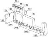
如图1~图9所示,本实例提供一种浸泡电路板转移装置,包括:支撑架100、夹持机构200、转移机构300、推送机构400。As shown in FIG. 1 to FIG. 9 , this example provides a transfer device for soaking circuit boards, including: a
支撑架100有两个,并且对称布置于传送带的一端,支撑架100靠近传送带的一端设有横板101,支撑架100内侧沿其长度方向设有支撑板102,支撑板102上设有多个间隔均匀的滚轮,并通过驱动源提供动力;夹持机构200设于支撑架100远离传送带的一端,包括两个安装于支撑架100上的弧形轨道212,两个弧形轨道212之间设有沿其轨迹移动的直线机构,直线机构的移动端上设有两个对称布置且运动方向相反的夹持组件,用于夹持电路板;转移机构300包括设于滚轮上的承载板301和两个竖直移动机构,承载板301用于承载夹持机构200夹持的电路板,竖直移动机构设于支撑架100外侧,用于将承载板301升起或降落;推送机构400设于支撑架100上方,用于将承载板301上的电路板推出。There are two supporting
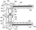
具体地,如图2~图5所示,在横板101远离传送带的一侧设有第一挡板103,横板101顶面设有第一凹部104,第一挡板103侧面设有两个水平布置的第一滑槽105,第一滑槽105内设有滑块106,滑块106一端设有插销107,插销107穿过第一凹部104,为了方便调节第一挡板103的高度,在第一凹部104的底部一侧还设有向上倾斜的斜槽108,用于穿过插销107,且斜槽108沿其轨迹方向设有多个限位槽109,在移动插销107后将其放置于限位槽109中。Specifically, as shown in FIGS. 2 to 5 , a
具体地,如图5所示,为了更加快速地将对电路板推送至传送带上,第一挡板103顶面还设有凸块110,凸块110朝向承载板301的一侧为弧形,当电路板与凸块110接触后,电路板会在其弧形侧的承托下翻起一定角度,从而使正在被推送的电路板与下一层电路板之间脱离面接触的状态。Specifically, as shown in FIG. 5 , in order to push the pair of circuit boards to the conveyor belt more quickly, the top surface of the
具体地,如图4和图5所示,为了避免第一挡板103在调整高度后倾倒,在横板101一侧设有卡槽111,并在第一挡板103两端设置卡板112,将卡板112穿设于卡槽111中,起到一定限位的作用。Specifically, as shown in FIG. 4 and FIG. 5 , in order to prevent the
具体地,如图6所示,夹持组件包括夹持框201,夹持框201呈U形,夹持框201上端连接于连板202上,连板202套设于直线机构的移动端上,连板202侧面在竖直方向设有两个支板203,其中位于上方的支板203设有双头伸缩杆204,双头伸缩杆204的移动端设有移动框205,两个移动框205之间可以同步运动,从而适应不同数量电路板的需求,同时为了保证移动框205在移动时能够更加平稳,其中位于下方的支板203两侧设有导杆206,移动框205上端穿设于导杆206上,导杆206一端设有挡块207,挡块207用于抵接到移动框205;移动框205侧面设有多个挡杆208,夹持框201内侧设有多个凹槽209,挡杆208穿设于凹槽209中,挡杆208用于与电路板侧面相接触,防止电路板滑落。Specifically, as shown in FIG. 6, the clamping assembly includes a
具体地,如图6所示,直线机构包括第一丝杆210,第一丝杆210安装于横杆211中,横杆211两端下方均设有导向框219,导向框219穿穿设于弧形轨道212上,第一丝杆210一端连接第一电机213,并由其驱动第一丝杆210转动,第一电机213安装于横杆211上,横杆211中心设有隔板214,隔板214将第一丝杆210的螺纹分隔为两段,且两段螺纹的旋向相反,连板202分别套设于第一丝杆210的两段螺纹上,则两个夹持框201可以同步相向或者反向运动,从而将转运车中的电路板夹起,横杆211两端的下部均穿设有转轴215,转轴215上套设有齿轮216,弧形轨道212内部设有齿圈217,齿轮216与齿圈217配合,转轴215一端连接第二电机218,第二电机218安装于导向框219上。Specifically, as shown in FIG. 6 , the linear mechanism includes a
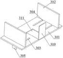
具体地,如图7和图8所示,转移机构300还包括侧板302,侧板302有两个,并分别设于承载板301长度方向两端,承载板301表面沿其长度方向设有多个对称布置的第二滑槽303,侧板302底面设有两个凸起304,凸起304穿设于第二滑槽303中,两个凸起304之间通过限位板305连接,且限位板305位于承载板301下方,这样就可以防止侧板302在移动过程中出现松动,承载板301底面中心沿其宽度方向设有凸台306,限位板305朝向凸台306的一侧设有顶杆307,且顶杆307穿过凸台306,为避免干涉同时也是为了使侧板302移动时更加稳定,两个限位板305的顶杆307之间交错布置,顶杆307一端还设有第一限位环308,顶杆307上套设有第一弹簧309,第一弹簧309两端分别抵接到第一限位环308和凸台306,在第一弹簧309的作用下,使侧板302始终具有朝向承载板301中心移动的趋势,从而对电路板侧面起到限位的作用。Specifically, as shown in FIG. 7 and FIG. 8 , the
具体地,如图8所示,承载板301靠近夹持机构200的一侧设有第二挡板310,用于在承载板301承接电路板后防止夹持机构200退出时电路板被拉动,第二挡板310下端通过铰接的方式与承载板301连接,且第二挡板310与承载板301的铰接部分具有阻尼力,使第二挡板310在被压迫转动后能够回复垂直状态,承载板301表面还设有第三凹部311,应用时,第二挡板310位于第三凹部311内。Specifically, as shown in FIG. 8 , the side of the
具体地,如图7所示,转移机构300还包括两个对称布置的伸缩杆312,伸缩杆312沿支撑架100的宽度方向设置并安装于连接块313上,连接块313套设于一水平移动机构的移动端上,且该水平移动机构安装于支撑架100底面并沿其长度方向设置,伸缩杆312的移动端设有推板314,推板314上端设有U形槽315,U形槽315用于穿过限位板305。Specifically, as shown in FIG. 7 , the
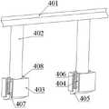
具体地,如图1和图9所示,推送机构400包括连杆401,连杆401两端套设于一水平移动机构的移动端上,且该水平移动机构沿支撑架100长度方向设置并安装于支撑架100的顶面,连杆401与支撑架100顶面之间有预定距离,这段距离不小于承载板301上移的距离,从而避免转移机构300与连杆401之间发生碰撞,连杆401底面设有两个对称布置的推杆402,推杆402下端设有推块403,推块403底面设有第二凹部404,第二凹部404内设有移动块405,移动块405上端设有滑杆406,滑杆406穿过推块403顶面,滑杆406上端设有第二限位环408,应用时,第二限位环408抵接到推块403,滑杆406上还套设有第二弹簧407,第二弹簧407两端分别抵接到移动块405顶面和第二凹部404底面,且第二弹簧407始终处于压缩状态,移动块405至少有一部分位于第二凹部404内,才能避免在推动电路板移动时,移动块405发生倾斜而影响推动效果,且朝向夹持机构200的一侧为弧形,且另一侧的直角板用于与电路板接触并推动电路板,同时移动块405被压迫进入第二凹部404后,在第二弹簧407的作用下可以弹出,就可以避免承载板301承接电路板向横板101移动过程中,移动块405与电路板之间发生干涉。Specifically, as shown in FIG. 1 and FIG. 9 , the
具体地,如图1~图4及图7所示,竖直移动机构及水平移动机构均包括第三丝杆501,第三丝杆501安装于支撑柱502中,第三丝杆501一端连接第三电机503,第三电机503安装于支撑柱502上,其中,竖直移动机构的第三丝杆501有四个,并且每两个设于支撑架100外侧,在竖直移动机构的第三丝杆501上套设有升降板504,用于托起承载板301,在不需要将承载板301升起时,升降板504处在支撑板102的下方。Specifically, as shown in FIG. 1 to FIG. 4 and FIG. 7 , both the vertical movement mechanism and the horizontal movement mechanism include a
具体的实施方式如下描述:The specific implementation is described as follows:
首先将装有电路板的转运车转移至夹持机构200下方,此时横杆211位于弧形轨道212的一端,夹持组件处于水平状态,然后启动第二电机218,驱使套设于转轴215上的齿轮216转动,在齿轮216与齿圈217配合下,横杆211开始转动,并带动夹持组件转动,直到横杆211处在弧形轨道212的最低点,此时夹持组件处于竖直状态,且电路板处在两个夹持组件之间,然后启动第一电机213,驱动第一丝杆210转动,由于第一丝杆210的两段螺纹旋向相反,使得两个夹持组件相向运动,在夹持框201抵接到电路板之后,启动双头伸缩杆204,使夹持框201两侧的移动框205都朝向夹持框201移动,直到移动框205都与电路板侧面相接触,然后再次启动第二电机218,驱使套设于转轴215上的齿轮216转动,使夹持组件朝向承载板301移动,直到夹持组件水平;First, transfer the transfer car with the circuit board to the bottom of the
然后启动滚轮,使承载板301朝向夹持机构200移动,此时同步启动位于支撑架100下方的第三电机503,驱动与之相连的第三丝杆501转动,带动推板314与承载板301同步移动,而承载板301下方的限位板305正处在推板314上端的U形槽315中,第一弹簧309也处于被进一步压缩的状态,使得侧板302处在承载板301的两端,而推板314与承载板301的同步移动保证侧板302在承载板301移动过程中不会被第一弹簧309拉动;Then start the roller to move the
且在承载板301移动过程中,第二挡板310被电路板压迫进入承载板301表面的第三凹部311中,此时承载板301继续移动,逐渐远离夹持组件,直到第二挡板310在阻尼力的作用下复位垂直状态,然后使滚轮反转,承载板301朝向推送机构400移动,在第二挡板310接触到夹持组件所夹持的电路板后,再次启动第一电机213,使两个夹持框201互相远离,电路板则落在承载板301上,然后承载板301继续朝向横板101移动,同时启动伸缩杆312,使两个推板314相向移动,从而带动两个侧板302相向移动,对电路板两侧进行限位;During the movement of the
在承载板301继续朝向横板101移动的过程中,移动块405在电路板的压迫下进入第二凹部404,当承载板301抵接到第一挡板103时,移动块405在第二弹簧407的作用下弹出,然后启动竖直移动机构的第三电机503,驱动与之相连的第三丝杆501转动,使升降板504向上移动,并将承载板301托起,然后继续向上移动预定距离,此时启动与连杆401连接的水平移动机构的第三电机503,带动连杆401朝向第一挡板103移动,在移动块405的推动下使最上一个电路板移动,在电路板移动至与第一挡板103上方的凸块110接触时,电路板被顶起一定角度,与下一层电路板脱离接触,能更加方便地将电路板推动,在移动块405移动至与第一挡板103接触时,电路板则落入支撑架100一侧的传送带上;During the continuous movement of the
若是需要传送不同厚度的电路板,则通过调整第一挡板103的高度即可,通过移动插销107的位置,使其斜槽108的限位槽109中,第一挡板103的高度能够多档调节,以适应不同厚度电路板的需求。If it is necessary to transport circuit boards with different thicknesses, the height of the
以上仅为本发明的优选实施例,并不用于限制本发明,显然,本领域的技术人员可以对本发明进行各种改动和变型而不脱离本发明的精神和范围。这样,倘若本发明的这些修改和变型属于本发明权利要求及其等同技术的范围之内,则本发明也意图包含这些改动和变型在内。The above are only preferred embodiments of the present invention and are not intended to limit the present invention. Obviously, those skilled in the art can make various changes and modifications to the present invention without departing from the spirit and scope of the present invention. Thus, provided that these modifications and variations of the present invention fall within the scope of the claims of the present invention and their equivalents, the present invention is also intended to include these modifications and variations.
Claims (10)
Translated fromChinesePriority Applications (1)
| Application Number | Priority Date | Filing Date | Title |
|---|---|---|---|
| CN202210437879.0ACN114538065B (en) | 2022-04-25 | 2022-04-25 | A immersion circuit board transfer device |
Applications Claiming Priority (1)
| Application Number | Priority Date | Filing Date | Title |
|---|---|---|---|
| CN202210437879.0ACN114538065B (en) | 2022-04-25 | 2022-04-25 | A immersion circuit board transfer device |
Publications (2)
| Publication Number | Publication Date |
|---|---|
| CN114538065Atrue CN114538065A (en) | 2022-05-27 |
| CN114538065B CN114538065B (en) | 2022-07-15 |
Family
ID=81666632
Family Applications (1)
| Application Number | Title | Priority Date | Filing Date |
|---|---|---|---|
| CN202210437879.0AActiveCN114538065B (en) | 2022-04-25 | 2022-04-25 | A immersion circuit board transfer device |
Country Status (1)
| Country | Link |
|---|---|
| CN (1) | CN114538065B (en) |
Cited By (9)
| Publication number | Priority date | Publication date | Assignee | Title |
|---|---|---|---|---|
| CN115064395A (en)* | 2022-08-18 | 2022-09-16 | 四川省科学城久信科技有限公司 | Capacitor assembling device |
| CN115116908A (en)* | 2022-08-22 | 2022-09-27 | 四川洪芯微科技有限公司 | Wafer groove corrosion device |
| CN115157370A (en)* | 2022-08-02 | 2022-10-11 | 成都清洋宝柏包装有限公司 | Blade replacing device |
| CN115279048A (en)* | 2022-09-26 | 2022-11-01 | 四川英创力电子科技股份有限公司 | An automatic conveying device for circuit board baking |
| CN115297619A (en)* | 2022-09-30 | 2022-11-04 | 四川英创力电子科技股份有限公司 | Printed circuit board centre gripping material feeding unit |
| CN115555774A (en)* | 2022-12-05 | 2023-01-03 | 成都群英创能光电科技有限公司 | Battery piece welding device |
| CN115592280A (en)* | 2022-12-13 | 2023-01-13 | 四川超声印制板有限公司(Cn) | Automatic cutting device and cutting method for printed circuit board |
| CN117226403A (en)* | 2023-11-09 | 2023-12-15 | 风通动力环境科技(成都)有限公司 | A valve frame welding device |
| CN118175743A (en)* | 2024-05-13 | 2024-06-11 | 四川英创力电子科技股份有限公司 | Pressfitting circuit board transfer device |
Citations (16)
| Publication number | Priority date | Publication date | Assignee | Title |
|---|---|---|---|---|
| JPS57195033A (en)* | 1981-05-23 | 1982-11-30 | Okura Yusoki Co Ltd | Pallet loading apparatus |
| US4907689A (en)* | 1986-09-23 | 1990-03-13 | Focke & Co., (Gmbh & Co.) | Apparatus for transporting reels of packaging material in a packaging machine plant |
| FR2655033A1 (en)* | 1989-11-28 | 1991-05-31 | Jaime Marti Sala | Device for bulk supply of a machine for uprighting and aligning containers |
| DE19650689A1 (en)* | 1996-12-06 | 1998-06-10 | Focke & Co | Device for handling stacks of blanks |
| JP2005239331A (en)* | 2004-02-25 | 2005-09-08 | Rengo Co Ltd | Feeder of underlay panel |
| CN101212894A (en)* | 2006-12-25 | 2008-07-02 | 英业达股份有限公司 | Feeding device |
| CN102602737A (en)* | 2011-12-15 | 2012-07-25 | 宁波荣大昌办公设备有限公司 | Connecting structure for paper folding box and lateral plates |
| CN103303687A (en)* | 2013-06-14 | 2013-09-18 | 南阳市天和机械有限公司 | Full-automatic brick stacking machine |
| CN206529059U (en)* | 2017-02-28 | 2017-09-29 | 福建省格绿木业有限公司 | Solid wood ecological board assembly line |
| CN207107207U (en)* | 2017-08-03 | 2018-03-16 | 东莞市高宇包装材料有限公司 | a safe tray |
| CN108190536A (en)* | 2018-01-17 | 2018-06-22 | 邱早生 | One kind automatically unloads brick device |
| CN110002034A (en)* | 2019-05-05 | 2019-07-12 | 山东瑞邦自动化设备有限公司 | Gloves transverse direction clamp device |
| CN110039314A (en)* | 2019-05-21 | 2019-07-23 | 重庆晋川精密五金有限公司 | A kind of titanium plate processing unit (plant) |
| CN110465958A (en)* | 2019-09-18 | 2019-11-19 | 厦门宏泰科技研究院有限公司 | A kind of circuit board turnover panel manipulator |
| CN211545157U (en)* | 2019-12-07 | 2020-09-22 | 刘昊城 | Manipulator clamping and moving device for material stacking |
| CN112977942A (en)* | 2021-04-30 | 2021-06-18 | 四川英创力电子科技股份有限公司 | Automatic pad pasting device in printed circuit board border |
- 2022
- 2022-04-25CNCN202210437879.0Apatent/CN114538065B/enactiveActive
Patent Citations (16)
| Publication number | Priority date | Publication date | Assignee | Title |
|---|---|---|---|---|
| JPS57195033A (en)* | 1981-05-23 | 1982-11-30 | Okura Yusoki Co Ltd | Pallet loading apparatus |
| US4907689A (en)* | 1986-09-23 | 1990-03-13 | Focke & Co., (Gmbh & Co.) | Apparatus for transporting reels of packaging material in a packaging machine plant |
| FR2655033A1 (en)* | 1989-11-28 | 1991-05-31 | Jaime Marti Sala | Device for bulk supply of a machine for uprighting and aligning containers |
| DE19650689A1 (en)* | 1996-12-06 | 1998-06-10 | Focke & Co | Device for handling stacks of blanks |
| JP2005239331A (en)* | 2004-02-25 | 2005-09-08 | Rengo Co Ltd | Feeder of underlay panel |
| CN101212894A (en)* | 2006-12-25 | 2008-07-02 | 英业达股份有限公司 | Feeding device |
| CN102602737A (en)* | 2011-12-15 | 2012-07-25 | 宁波荣大昌办公设备有限公司 | Connecting structure for paper folding box and lateral plates |
| CN103303687A (en)* | 2013-06-14 | 2013-09-18 | 南阳市天和机械有限公司 | Full-automatic brick stacking machine |
| CN206529059U (en)* | 2017-02-28 | 2017-09-29 | 福建省格绿木业有限公司 | Solid wood ecological board assembly line |
| CN207107207U (en)* | 2017-08-03 | 2018-03-16 | 东莞市高宇包装材料有限公司 | a safe tray |
| CN108190536A (en)* | 2018-01-17 | 2018-06-22 | 邱早生 | One kind automatically unloads brick device |
| CN110002034A (en)* | 2019-05-05 | 2019-07-12 | 山东瑞邦自动化设备有限公司 | Gloves transverse direction clamp device |
| CN110039314A (en)* | 2019-05-21 | 2019-07-23 | 重庆晋川精密五金有限公司 | A kind of titanium plate processing unit (plant) |
| CN110465958A (en)* | 2019-09-18 | 2019-11-19 | 厦门宏泰科技研究院有限公司 | A kind of circuit board turnover panel manipulator |
| CN211545157U (en)* | 2019-12-07 | 2020-09-22 | 刘昊城 | Manipulator clamping and moving device for material stacking |
| CN112977942A (en)* | 2021-04-30 | 2021-06-18 | 四川英创力电子科技股份有限公司 | Automatic pad pasting device in printed circuit board border |
Non-Patent Citations (3)
| Title |
|---|
| 张仁军等: "多层板孔内空洞缺陷的改善", 《印制电路信息》* |
| 张翔: "西斯派克贴标机高速视觉定位系统", 《酒?饮料技术装备》* |
| 牛同威等: "冲压线板料拆垛系统挡料器装置的研发与应用", 《设备管理与维修》* |
Cited By (17)
| Publication number | Priority date | Publication date | Assignee | Title |
|---|---|---|---|---|
| CN115157370A (en)* | 2022-08-02 | 2022-10-11 | 成都清洋宝柏包装有限公司 | Blade replacing device |
| CN115157370B (en)* | 2022-08-02 | 2023-12-29 | 成都清洋宝柏包装有限公司 | Blade replacing device |
| CN115064395B (en)* | 2022-08-18 | 2022-10-28 | 四川省科学城久信科技有限公司 | Capacitor assembling device |
| CN115064395A (en)* | 2022-08-18 | 2022-09-16 | 四川省科学城久信科技有限公司 | Capacitor assembling device |
| CN115116908B (en)* | 2022-08-22 | 2023-01-10 | 四川洪芯微科技有限公司 | Wafer groove corrosion device |
| CN115116908A (en)* | 2022-08-22 | 2022-09-27 | 四川洪芯微科技有限公司 | Wafer groove corrosion device |
| CN115279048A (en)* | 2022-09-26 | 2022-11-01 | 四川英创力电子科技股份有限公司 | An automatic conveying device for circuit board baking |
| CN115279048B (en)* | 2022-09-26 | 2022-12-16 | 四川英创力电子科技股份有限公司 | An automatic conveying device for circuit board baking |
| CN115297619B (en)* | 2022-09-30 | 2023-02-03 | 四川英创力电子科技股份有限公司 | A clamping and feeding device for printed circuit boards |
| CN115297619A (en)* | 2022-09-30 | 2022-11-04 | 四川英创力电子科技股份有限公司 | Printed circuit board centre gripping material feeding unit |
| CN115555774A (en)* | 2022-12-05 | 2023-01-03 | 成都群英创能光电科技有限公司 | Battery piece welding device |
| CN115555774B (en)* | 2022-12-05 | 2023-03-24 | 成都群英创能光电科技有限公司 | Battery piece welding device |
| CN115592280A (en)* | 2022-12-13 | 2023-01-13 | 四川超声印制板有限公司(Cn) | Automatic cutting device and cutting method for printed circuit board |
| CN117226403A (en)* | 2023-11-09 | 2023-12-15 | 风通动力环境科技(成都)有限公司 | A valve frame welding device |
| CN117226403B (en)* | 2023-11-09 | 2024-02-06 | 风通动力环境科技(成都)有限公司 | A valve frame welding device |
| CN118175743A (en)* | 2024-05-13 | 2024-06-11 | 四川英创力电子科技股份有限公司 | Pressfitting circuit board transfer device |
| CN118175743B (en)* | 2024-05-13 | 2024-07-09 | 四川英创力电子科技股份有限公司 | A device for transferring pressed circuit board |
Also Published As
| Publication number | Publication date |
|---|---|
| CN114538065B (en) | 2022-07-15 |
Similar Documents
| Publication | Publication Date | Title |
|---|---|---|
| CN114538065B (en) | A immersion circuit board transfer device | |
| KR100754831B1 (en) | Printed Circuit Board Inverter | |
| CN115297619B (en) | A clamping and feeding device for printed circuit boards | |
| CN203984793U (en) | The turning device of printed circuit board | |
| TW202203365A (en) | Surface treatment equipment | |
| CN114313925B (en) | Printed circuit board conveying and turning device and method | |
| CN118597747B (en) | A new energy vehicle battery processing flip device | |
| CN110918695B (en) | A kind of double-sided straightening device and straightening method for slender rod | |
| CN113562445A (en) | Feeding and discharging parallel type bearing roller ultrasonic liquid immersion detection structure | |
| CN217920158U (en) | Temporary storage machine with steering conveying function | |
| CN215710043U (en) | Sheet material horizontal and vertical conversion conveying device | |
| CN113445111B (en) | Electroplating hanger for circuit board | |
| CN115319615A (en) | A rust cleaning device for conveyer cylinder | |
| CN218706888U (en) | Automatic cylinder assembling production line | |
| JPH11186798A (en) | Printed board supporting apparatus | |
| JPH08169578A (en) | Throwing-in method of base board and its device | |
| CN222638808U (en) | PCBA circuit board production is with getting piece device | |
| CN222710529U (en) | A rolling equipment for stainless steel product processing | |
| CN110525947A (en) | A kind of automobile decoration piece plating continuous conveying device and its working method | |
| CN221521279U (en) | Glass plate conveying device | |
| CN221564681U (en) | High-efficient transfer chain revolving stage device | |
| CN220200390U (en) | Conveying equipment with high adaptability | |
| CN216763164U (en) | A feed mechanism for printing for paper products | |
| CN209778161U (en) | Eccentric lifting device for automobile production conveying line | |
| CN213140440U (en) | Conveying device |
Legal Events
| Date | Code | Title | Description |
|---|---|---|---|
| PB01 | Publication | ||
| PB01 | Publication | ||
| SE01 | Entry into force of request for substantive examination | ||
| SE01 | Entry into force of request for substantive examination | ||
| GR01 | Patent grant | ||
| GR01 | Patent grant |