CN114537055A - Wireless receiving system and method for automobile - Google Patents
Wireless receiving system and method for automobileDownload PDFInfo
- Publication number
- CN114537055A CN114537055ACN202210242313.2ACN202210242313ACN114537055ACN 114537055 ACN114537055 ACN 114537055ACN 202210242313 ACN202210242313 ACN 202210242313ACN 114537055 ACN114537055 ACN 114537055A
- Authority
- CN
- China
- Prior art keywords
- signal
- wireless
- microprocessor
- remote control
- control key
- Prior art date
- Legal status (The legal status is an assumption and is not a legal conclusion. Google has not performed a legal analysis and makes no representation as to the accuracy of the status listed.)
- Pending
Links
- 238000000034methodMethods0.000titleclaimsabstractdescription34
- 230000008054signal transmissionEffects0.000claimsabstractdescription21
- 230000005540biological transmissionEffects0.000claimsdescription7
- 238000012360testing methodMethods0.000abstractdescription4
- 230000001960triggered effectEffects0.000abstractdescription3
- 239000003990capacitorSubstances0.000description10
- 238000010586diagramMethods0.000description9
- 238000001514detection methodMethods0.000description5
- 230000008569processEffects0.000description5
- 238000004891communicationMethods0.000description3
- 238000005259measurementMethods0.000description3
- 238000012544monitoring processMethods0.000description3
- 230000006872improvementEffects0.000description2
- 230000010354integrationEffects0.000description2
- 238000012986modificationMethods0.000description2
- 230000004048modificationEffects0.000description2
- 230000010363phase shiftEffects0.000description2
- 230000009286beneficial effectEffects0.000description1
- 230000008859changeEffects0.000description1
- 230000021615conjugationEffects0.000description1
- 239000013078crystalSubstances0.000description1
- 230000007812deficiencyEffects0.000description1
- 238000013461designMethods0.000description1
- 238000011161developmentMethods0.000description1
- 238000005516engineering processMethods0.000description1
- 230000007613environmental effectEffects0.000description1
- 239000012634fragmentSubstances0.000description1
- 230000003287optical effectEffects0.000description1
- 238000005457optimizationMethods0.000description1
- 230000010355oscillationEffects0.000description1
- 238000003672processing methodMethods0.000description1
- 230000035945sensitivityEffects0.000description1
Images


Classifications
- B—PERFORMING OPERATIONS; TRANSPORTING
- B60—VEHICLES IN GENERAL
- B60C—VEHICLE TYRES; TYRE INFLATION; TYRE CHANGING; CONNECTING VALVES TO INFLATABLE ELASTIC BODIES IN GENERAL; DEVICES OR ARRANGEMENTS RELATED TO TYRES
- B60C23/00—Devices for measuring, signalling, controlling, or distributing tyre pressure or temperature, specially adapted for mounting on vehicles; Arrangement of tyre inflating devices on vehicles, e.g. of pumps or of tanks; Tyre cooling arrangements
- B60C23/02—Signalling devices actuated by tyre pressure
- B60C23/04—Signalling devices actuated by tyre pressure mounted on the wheel or tyre
- B60C23/0408—Signalling devices actuated by tyre pressure mounted on the wheel or tyre transmitting the signals by non-mechanical means from the wheel or tyre to a vehicle body mounted receiver
- B60C23/0422—Signalling devices actuated by tyre pressure mounted on the wheel or tyre transmitting the signals by non-mechanical means from the wheel or tyre to a vehicle body mounted receiver characterised by the type of signal transmission means
- B60C23/0433—Radio signals
- B60C23/0447—Wheel or tyre mounted circuits
- B60C23/0455—Transmission control of wireless signals
- B—PERFORMING OPERATIONS; TRANSPORTING
- B60—VEHICLES IN GENERAL
- B60C—VEHICLE TYRES; TYRE INFLATION; TYRE CHANGING; CONNECTING VALVES TO INFLATABLE ELASTIC BODIES IN GENERAL; DEVICES OR ARRANGEMENTS RELATED TO TYRES
- B60C23/00—Devices for measuring, signalling, controlling, or distributing tyre pressure or temperature, specially adapted for mounting on vehicles; Arrangement of tyre inflating devices on vehicles, e.g. of pumps or of tanks; Tyre cooling arrangements
- B60C23/02—Signalling devices actuated by tyre pressure
- B60C23/04—Signalling devices actuated by tyre pressure mounted on the wheel or tyre
- B60C23/0408—Signalling devices actuated by tyre pressure mounted on the wheel or tyre transmitting the signals by non-mechanical means from the wheel or tyre to a vehicle body mounted receiver
- B60C23/0479—Communicating with external units being not part of the vehicle, e.g. tools for diagnostic, mobile phones, electronic keys or service stations
- Y—GENERAL TAGGING OF NEW TECHNOLOGICAL DEVELOPMENTS; GENERAL TAGGING OF CROSS-SECTIONAL TECHNOLOGIES SPANNING OVER SEVERAL SECTIONS OF THE IPC; TECHNICAL SUBJECTS COVERED BY FORMER USPC CROSS-REFERENCE ART COLLECTIONS [XRACs] AND DIGESTS
- Y02—TECHNOLOGIES OR APPLICATIONS FOR MITIGATION OR ADAPTATION AGAINST CLIMATE CHANGE
- Y02D—CLIMATE CHANGE MITIGATION TECHNOLOGIES IN INFORMATION AND COMMUNICATION TECHNOLOGIES [ICT], I.E. INFORMATION AND COMMUNICATION TECHNOLOGIES AIMING AT THE REDUCTION OF THEIR OWN ENERGY USE
- Y02D30/00—Reducing energy consumption in communication networks
- Y02D30/70—Reducing energy consumption in communication networks in wireless communication networks
Landscapes
- Engineering & Computer Science (AREA)
- Mechanical Engineering (AREA)
- Computer Networks & Wireless Communication (AREA)
- Arrangements For Transmission Of Measured Signals (AREA)
- Measuring Fluid Pressure (AREA)
Abstract
Description
Translated fromChinese技术领域technical field
本发明涉及无线通讯技术领域,特别是涉及用于汽车的无线接收系统及方法。The present invention relates to the technical field of wireless communication, in particular to a wireless receiving system and method for automobiles.
背景技术Background technique
本部分的陈述仅仅是提到了与本发明相关的背景技术,并不必然构成现有技术。The statements in this section merely provide background related to the present disclosure and do not necessarily constitute prior art.
随着汽车智能化的发展,目前的中高端汽车大多集成胎压监测系统,用于实时监测轮胎胎压。汽车胎压监测系统包括发射器和接收器,发射器一般安装在汽车轮胎的气嘴上,接收器用于接收各轮胎发射的无线数据。遥控钥匙一直是汽车的标配,用于实现汽车的解/闭锁,其无线接收电路集成在车身控制器中,与车身控制器共用一个微处理器。With the development of automobile intelligence, most of the current mid-to-high-end automobiles integrate tire pressure monitoring systems to monitor tire pressure in real time. The automobile tire pressure monitoring system includes a transmitter and a receiver. The transmitter is generally installed on the air nozzle of the automobile tire, and the receiver is used to receive the wireless data transmitted by each tire. The remote control key has always been the standard configuration of the car, which is used to realize the unlocking/locking of the car. Its wireless receiving circuit is integrated in the body controller and shares a microprocessor with the body controller.
目前有的汽车厂的胎压监测系统的接收器采用单独的微处理器和无线接收电路接收其发射器的胎压数据,然后通过RS-232或者CAN总线将胎压数据发送给车身控制器或者汽车仪表,该方式软件实现简单,但硬件成本较高。虽然胎压接收器和遥控钥匙分别采用独立的无线接收电路,但是胎压发射器和遥控钥匙一旦采用相同频率的无线载波,还是会发生由于无线数据碰撞导致数据丢失或者错误。At present, the receiver of the tire pressure monitoring system of some automobile factories adopts a separate microprocessor and wireless receiving circuit to receive the tire pressure data of its transmitter, and then sends the tire pressure data to the body controller or the body controller through RS-232 or CAN bus. Car instrument, this method is simple to implement in software, but the hardware cost is high. Although the tire pressure receiver and the remote control key use independent wireless receiving circuits, once the tire pressure transmitter and the remote control key use the same frequency wireless carrier, data loss or error will still occur due to wireless data collision.
中国专利CN 108173961 B公开了一种通过使胎压发射器和遥控钥匙工作在同一载波频率,但采用不同的调制方式,接收端的微处理器通过交替配置无线接收芯片参数以轮询胎压和遥控器发射的无线数据帧的前导码段,从而实现胎压和遥控钥匙识别,进而完成一个无线接收电路同时接收胎压和遥控钥匙的无线信号,该方案有效地降低了硬件成本。但由于接收芯片采用胎压和遥控钥匙无线参数轮询配置方式,消耗微处理器资源多,待机电流较大;由于接收端通过无线数据帧的前导码段,因此要求无线发射端的前导码段较长,导致胎压发射器和遥控钥匙的使用寿命变短。Chinese patent CN 108173961 B discloses a method by making the tire pressure transmitter and the remote control key work at the same carrier frequency, but using different modulation methods, the microprocessor at the receiving end configures the parameters of the wireless receiving chip alternately to poll the tire pressure and remote control The preamble segment of the wireless data frame transmitted by the transmitter can realize the identification of tire pressure and remote control key, and then complete a wireless receiving circuit to receive the wireless signal of tire pressure and remote control key at the same time, which effectively reduces the hardware cost. However, because the receiving chip adopts the tire pressure and remote control key wireless parameter polling configuration method, it consumes a lot of microprocessor resources and the standby current is large; since the receiving end passes the preamble segment of the wireless data frame, the preamble segment of the wireless transmitter is required to be relatively small. long, resulting in a shorter service life of the tire pressure transmitter and remote control key.
发明内容SUMMARY OF THE INVENTION
为了解决现有技术的不足,本发明提供了用于汽车的无线接收系统及方法;通过在接收系统中增加无线信号强度检测器,能够在更短的时间内判断出信号的调制试,无需无线发射端的增加前导码段,更节省发射端设备的能量。In order to solve the deficiencies of the prior art, the present invention provides a wireless receiving system and method for automobiles; by adding a wireless signal strength detector in the receiving system, the modulation test of the signal can be determined in a shorter time, without the need for wireless The addition of the preamble segment at the transmitting end saves the energy of the transmitting end device.
第一方面,本发明提供了用于汽车的无线接收系统;In a first aspect, the present invention provides a wireless receiving system for an automobile;
用于汽车的无线接收系统,包括:接收天线;所述接收天线通过无线接收电路与微处理器连接;所述接收天线通过无线信号强度检测器与微处理器连接;A wireless receiving system for an automobile, comprising: a receiving antenna; the receiving antenna is connected with a microprocessor through a wireless receiving circuit; the receiving antenna is connected with the microprocessor through a wireless signal strength detector;
所述接收天线用于接收胎压发射器发射的信号和遥控钥匙发射的信号;The receiving antenna is used for receiving the signal transmitted by the tire pressure transmitter and the signal transmitted by the remote control key;
所述接收天线将接收的信号传输给无线信号强度检测器;the receiving antenna transmits the received signal to the wireless signal strength detector;
所述无线信号强度检测器,对是否检测到信号进行判断;如果检测到载波频率的无线信号,就输出高电平信号给微处理器;如果未检测到载波频率的无线信号,就输出低电平信号给微处理器;The wireless signal strength detector judges whether the signal is detected; if the wireless signal of the carrier frequency is detected, it outputs a high-level signal to the microprocessor; if the wireless signal of the carrier frequency is not detected, it outputs a low-level signal. level signal to the microprocessor;
微处理器收到高电平信号后,触发计时器开始计时;微处理器收到低电平信号后,触发计时器停止计时;After the microprocessor receives the high-level signal, the trigger timer starts timing; after the microprocessor receives the low-level signal, the trigger timer stops timing;
微处理器,对从计时器开始计时到计时器停止计时期间接收到的信号传输时间进行统计;如果信号传输时间触发设定第一阈值,则微处理器控制无线接收电路接收遥控钥匙发射的信号;如果信号传输时间触发设定第二阈值,则微处理器控制无线接收电路接收胎压发射器发射的信号。The microprocessor counts the signal transmission time received during the period from when the timer starts timing to when the timer stops timing; if the signal transmission time triggers the setting of the first threshold, the microprocessor controls the wireless receiving circuit to receive the signal transmitted by the remote control key ; If the signal transmission time triggers the setting of the second threshold, the microprocessor controls the wireless receiving circuit to receive the signal transmitted by the tire pressure transmitter.
第二方面,本发明提供了用于汽车的无线接收系统的工作方法;In a second aspect, the present invention provides a working method of a wireless receiving system for an automobile;
用于汽车的无线接收系统的工作方法,包括:A working method of a wireless receiving system for an automobile, including:
接收天线接收胎压发射器发射的信号和遥控钥匙发射的信号;The receiving antenna receives the signal transmitted by the tire pressure transmitter and the signal transmitted by the remote key;
接收天线将接收的信号传输给无线信号强度检测器;The receiving antenna transmits the received signal to the wireless signal strength detector;
无线信号强度检测器,对是否检测到信号进行判断;如果检测到载波频率的无线信号,就输出高电平信号给微处理器;如果未检测到载波频率的无线信号,就输出低电平信号给微处理器;The wireless signal strength detector judges whether the signal is detected; if the wireless signal of the carrier frequency is detected, it outputs a high-level signal to the microprocessor; if the wireless signal of the carrier frequency is not detected, it outputs a low-level signal to the microprocessor;
微处理器收到高电平信号后,触发计时器开始计时;微处理器收到低电平信号后,触发计时器停止计时;After the microprocessor receives the high-level signal, the trigger timer starts timing; after the microprocessor receives the low-level signal, the trigger timer stops timing;
微处理器对从计时器开始计时到计时器停止计时期间接收到的信号传输时间进行统计;如果信号传输时间触发设定第一阈值,则微处理器控制无线接收电路接收遥控钥匙发射的信号;如果信号传输时间触发设定第二阈值,则微处理器控制无线接收电路接收胎压发射器发射的信号。The microprocessor counts the signal transmission time received during the period from when the timer starts timing to when the timer stops timing; if the signal transmission time triggers the setting of the first threshold, the microprocessor controls the wireless receiving circuit to receive the signal transmitted by the remote control key; If the signal transmission time triggers the setting of the second threshold, the microprocessor controls the wireless receiving circuit to receive the signal transmitted by the tire pressure transmitter.
与现有技术相比,本发明的有益效果是:Compared with the prior art, the beneficial effects of the present invention are:
本发明实现了通过单一无线接收电路接收两种不同调制方式的无线信号,降低了硬件成本;通过在接收系统中增加无线信号强度检测器,能够在更短的时间内判断出信号的调制方式,无需无线发射端的增加前导码段,更节省发射端设备的能量;另外通过车速信号调整优先接收或者提取特征码的匹配数据,更有利于准确地判断胎压和遥控钥匙无线信号,有效地减少了微处理器轮询配置胎压和遥控钥匙无线参数的频率,降低了接收端的电能消耗,特别是汽车静止时的待机电流消耗。由于接收器根据车速信号调整胎压和遥控钥匙的无线参数配置时间,不再通过无线数据帧的前导码段的具体数值来识别调制方式,因此胎压和遥控钥匙的前导码段还可以设计的更短,从而有效地减小了胎压发射器和遥控钥匙的无线发射时间,进一步延长胎压发射器和遥控钥匙的电池寿命。The invention realizes receiving wireless signals of two different modulation modes through a single wireless receiving circuit, and reduces the hardware cost; by adding a wireless signal strength detector in the receiving system, the modulation mode of the signal can be judged in a shorter time, There is no need to increase the preamble segment of the wireless transmitter, which saves the energy of the transmitter device; in addition, the vehicle speed signal is adjusted to receive priority or extract the matching data of the feature code, which is more conducive to accurately determine the tire pressure and the wireless signal of the remote control key, effectively reducing the number of The frequency of the microprocessor polling to configure the tire pressure and the wireless parameters of the remote control key reduces the power consumption of the receiver, especially the standby current consumption when the car is stationary. Since the receiver adjusts the tire pressure and the wireless parameter configuration time of the remote control key according to the vehicle speed signal, and no longer identifies the modulation method by the specific value of the preamble segment of the wireless data frame, the tire pressure and the preamble segment of the remote control key can also be designed Shorter, thus effectively reducing the wireless transmission time of the tire pressure transmitter and the remote control key, and further extending the battery life of the tire pressure transmitter and the remote control key.
附图说明Description of drawings
构成本发明的一部分的说明书附图用来提供对本发明的进一步理解,本发明的示意性实施例及其说明用于解释本发明,并不构成对本发明的不当限定。The accompanying drawings forming a part of the present invention are used to provide further understanding of the present invention, and the exemplary embodiments of the present invention and their descriptions are used to explain the present invention, and do not constitute an improper limitation of the present invention.
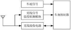
图1为第一个实施例中汽车无线接收系统的内部功能模块示意图;1 is a schematic diagram of the internal functional modules of the car wireless receiving system in the first embodiment;
图2为第一个实施例的遥控钥匙采用ASK调制方式;Fig. 2 adopts ASK modulation mode for the remote control key of the first embodiment;
图3为第一个实施例的胎压发射器采用FSK调制方式;Fig. 3 is that the tire pressure transmitter of the first embodiment adopts the FSK modulation method;
图4为第一个实施例中汽车无线接收系统的内部功能模块示意图;4 is a schematic diagram of the internal functional modules of the car wireless receiving system in the first embodiment;
图5为第一个实施例中汽车无线接收系统的内部功能模块示意图;5 is a schematic diagram of the internal functional modules of the car wireless receiving system in the first embodiment;
图6为第一个实施例中汽车无线接收系统的内部功能模块示意图;6 is a schematic diagram of the internal functional modules of the car wireless receiving system in the first embodiment;
图7为第一个实施例中汽车无线接收系统的内部功能模块示意图;7 is a schematic diagram of the internal functional modules of the car wireless receiving system in the first embodiment;
图8为第一个实施例中汽车无线接收系统的内部功能模块示意图;8 is a schematic diagram of the internal functional modules of the car wireless receiving system in the first embodiment;
图9为第一个实施例中汽车无线接收系统的内部功能模块示意图;9 is a schematic diagram of the internal functional modules of the car wireless receiving system in the first embodiment;
图10为第一个实施例胎压发射器发送的无线数据格式;Fig. 10 is the wireless data format sent by the tire pressure transmitter of the first embodiment;
图11为第一个实施例遥控钥匙发送的无线数据格式;Fig. 11 is the wireless data format sent by the remote control key of the first embodiment;
图12为第一个实施例无线接收电路和无线信号强度检测器的优选实施方案。FIG. 12 is a preferred embodiment of the wireless receiving circuit and the wireless signal strength detector of the first embodiment.
具体实施方式Detailed ways
应该指出,以下详细说明都是示例性的,旨在对本发明提供进一步的说明。除非另有指明,本文使用的所有技术和科学术语具有与本发明所属技术领域的普通技术人员通常理解的相同含义。It should be noted that the following detailed description is exemplary and intended to provide further explanation of the invention. Unless otherwise defined, all technical and scientific terms used herein have the same meaning as commonly understood by one of ordinary skill in the art to which this invention belongs.
需要注意的是,这里所使用的术语仅是为了描述具体实施方式,而非意图限制根据本发明的示例性实施方式。如在这里所使用的,除非上下文另外明确指出,否则单数形式也意图包括复数形式,此外,还应当理解的是,术语“包括”和“具有”以及他们的任何变形,意图在于覆盖不排他的包含,例如,包含了一系列步骤或单元的过程、方法、系统、产品或设备不必限于清楚地列出的那些步骤或单元,而是可包括没有清楚地列出的或对于这些过程、方法、产品或设备固有的其它步骤或单元。It should be noted that the terminology used herein is for the purpose of describing specific embodiments only, and is not intended to limit the exemplary embodiments according to the present invention. As used herein, unless the context clearly dictates otherwise, the singular is intended to include the plural as well, furthermore, it is to be understood that the terms "including" and "having" and any conjugations thereof are intended to cover the non-exclusive A process, method, system, product or device comprising, for example, a series of steps or units is not necessarily limited to those steps or units expressly listed, but may include those steps or units not expressly listed or for such processes, methods, Other steps or units inherent to the product or equipment.
在不冲突的情况下,本发明中的实施例及实施例中的特征可以相互组合。Embodiments of the invention and features of the embodiments may be combined with each other without conflict.
本实施例所有数据的获取都在符合法律法规和用户同意的基础上,对数据的合法应用。All data acquisition in this embodiment is based on compliance with laws and regulations and the user's consent, and the legal application of the data.
无线通讯中基带信号是原始的电信号,一般是指基本的信号波形,在数字通信中则指相应的电脉冲。在无线遥测遥控系统和无线电技术中的调制就是用基带信号控制高频载波的参数(振幅、频率和相位),使这些参数随基带信号变化,用来控制高频载波参数的基带信号称为调制信号。未调制的高频电振荡称为载波(可以是正弦波,也可以是非正弦波,如方波、脉冲序列等)。调制方式按照调制信号的性质分为模拟调制和数字调制两类;按照载波的形式分为连续波调制和脉冲调制两类。模拟调制有调幅(AM)、调频(FM)和调相(PM);数字调制有振幅键控(ASK)、移频键控(FSK)、移相键控(PSK)和差分移相键控(DPSK)等;脉冲调制有脉幅调制(PAM)、脉宽调制(PWM)、脉频调制(PFM)、脉位调制(PPM)、脉码调制(PCM)和增量调制(ΔM)。实施例中的ASK和FSK是无线信号的数字调制方式。In wireless communication, the baseband signal is the original electrical signal, which generally refers to the basic signal waveform, and in digital communication, it refers to the corresponding electrical pulse. Modulation in wireless telemetry and remote control systems and radio technology is to use baseband signals to control the parameters (amplitude, frequency and phase) of the high-frequency carrier, so that these parameters change with the baseband signal, and the baseband signal used to control the parameters of the high-frequency carrier is called modulation Signal. The unmodulated high-frequency electrical oscillation is called the carrier wave (which can be a sine wave or a non-sinusoidal wave, such as a square wave, pulse train, etc.). Modulation methods can be divided into analog modulation and digital modulation according to the nature of the modulating signal; continuous wave modulation and pulse modulation according to the form of the carrier wave. Analog modulation includes amplitude modulation (AM), frequency modulation (FM) and phase modulation (PM); digital modulation includes amplitude modulation (ASK), frequency shift keying (FSK), phase shift keying (PSK) and differential phase shift keying (DPSK), etc.; Pulse modulation includes Pulse Amplitude Modulation (PAM), Pulse Width Modulation (PWM), Pulse Frequency Modulation (PFM), Pulse Position Modulation (PPM), Pulse Code Modulation (PCM) and Delta Modulation (ΔM). ASK and FSK in the embodiment are digital modulation methods of wireless signals.
实施例一Example 1
本实施例提供了用于汽车的无线接收系统;This embodiment provides a wireless receiving system for an automobile;
如图1所示,用于汽车的无线接收系统,包括:接收天线;所述接收天线通过无线接收电路与微处理器连接;所述接收天线通过无线信号强度检测器与微处理器连接;As shown in Figure 1, a wireless receiving system for automobiles includes: a receiving antenna; the receiving antenna is connected to a microprocessor through a wireless receiving circuit; the receiving antenna is connected to the microprocessor through a wireless signal strength detector;
所述接收天线用于接收胎压发射器发射的信号和遥控钥匙发射的信号;The receiving antenna is used for receiving the signal transmitted by the tire pressure transmitter and the signal transmitted by the remote control key;
所述接收天线将接收的信号传输给无线信号强度检测器;the receiving antenna transmits the received signal to the wireless signal strength detector;
所述无线信号强度检测器,对是否检测到信号进行判断;如果检测到载波频率的无线信号,就输出高电平信号给微处理器;如果未检测到载波频率的无线信号,就输出低电平信号给微处理器;The wireless signal strength detector judges whether the signal is detected; if the wireless signal of the carrier frequency is detected, it outputs a high-level signal to the microprocessor; if the wireless signal of the carrier frequency is not detected, it outputs a low-level signal. level signal to the microprocessor;
微处理器收到高电平信号后,触发计时器开始计时;微处理器收到低电平信号后,触发计时器停止计时;After the microprocessor receives the high-level signal, the trigger timer starts timing; after the microprocessor receives the low-level signal, the trigger timer stops timing;
微处理器,对从计时器开始计时到计时器停止计时期间接收到的信号传输时间进行统计;如果信号传输时间触发设定第一阈值,则微处理器控制无线接收电路接收遥控钥匙发射的信号;如果信号传输时间触发设定第二阈值,则微处理器控制无线接收电路接收胎压发射器发射的信号。The microprocessor counts the signal transmission time received during the period from when the timer starts timing to when the timer stops timing; if the signal transmission time triggers the setting of the first threshold, the microprocessor controls the wireless receiving circuit to receive the signal transmitted by the remote control key ; If the signal transmission time triggers the setting of the second threshold, the microprocessor controls the wireless receiving circuit to receive the signal transmitted by the tire pressure transmitter.
进一步地,所述无线信号强度检测器采用信号强度测试仪来实现。Further, the wireless signal strength detector is implemented by a signal strength tester.
或者,所述无线信号强度检测器和无线接收电路,利用无线接收芯片来实现。Alternatively, the wireless signal strength detector and the wireless receiving circuit are implemented by using a wireless receiving chip.
如图2所示,所述无线接收芯片为TDA52302芯片;As shown in Figure 2, the wireless receiving chip is a TDA52302 chip;
所述TDA52302芯片的GNDA引脚接地,所述TDA52302芯片的GNDA引脚与滤波器Q1的GND端连接;所述TDA52302芯片的LIM-IN+引脚与滤波器Q1的OUT端连接;所述TDA52302芯片的IF-OUT引脚与滤波器Q1的IN端连接;The GNDA pin of the TDA52302 chip is grounded, and the GNDA pin of the TDA52302 chip is connected to the GND end of the filter Q1; the LIM-IN+ pin of the TDA52302 chip is connected to the OUT end of the filter Q1; the TDA52302 chip The IF-OUT pin is connected to the IN terminal of the filter Q1;
所述TDA52302芯片的LIM-IN-引脚接地;所述TDA52302芯片的VDD5V引脚与5V电源连接;所述TDA52302芯片的VDD5V引脚还通过电容V6接地;所述TDA52302芯片的VDDD引脚通过电容C3接地;所述TDA52302芯片的VDDD1V5引脚通过电容C4接地;The LIM-IN-pin of the TDA52302 chip is grounded; the VDD5V pin of the TDA52302 chip is connected to the 5V power supply; the VDD5V pin of the TDA52302 chip is also grounded through the capacitor V6; the VDDD pin of the TDA52302 chip is connected to the ground through the capacitor C3 is grounded; the VDDD1V5 pin of the TDA52302 chip is grounded through capacitor C4;
所述TDA52302芯片的GNDD引脚接地;The GNDD pin of the TDA52302 chip is grounded;
所述TDA52302芯片的NINT/NSTR引脚连接微处理器的中断输入引脚;The NINT/NSTR pin of the TDA52302 chip is connected to the interrupt input pin of the microprocessor;
所述TDA52302芯片的P-ON引脚是TDA5230芯片的输入引脚,由微处理器的输出引脚进行控制,实现TDA5230芯片的关断和开启;The P-ON pin of the TDA52302 chip is the input pin of the TDA5230 chip, and is controlled by the output pin of the microprocessor to turn off and on the TDA5230 chip;
所述TDA52302芯片的XTAL1引脚依次通过电容C7和电容C8与TDA52302芯片的XTAL2引脚连接;电容C7和电容C8的中间连接点接地;The XTAL1 pin of the TDA52302 chip is connected to the XTAL2 pin of the TDA52302 chip through the capacitor C7 and the capacitor C8 in turn; the intermediate connection point of the capacitor C7 and the capacitor C8 is grounded;
所述TDA52302芯片的XTAL1引脚还通过晶振与TDA52302芯片的XTAL2引脚连接;The XTAL1 pin of the TDA52302 chip is also connected to the XTAL2 pin of the TDA52302 chip through a crystal oscillator;
所述TDA52302芯片的SDO、SDI、SCK、NCS引脚与微处理器的SPI接口的对应引脚连接;The SDO, SDI, SCK, NCS pins of the TDA52302 chip are connected with the corresponding pins of the SPI interface of the microprocessor;
所述TDA52302芯片的T1引脚、T2引脚和RFIN-引脚均接地;The T1 pin, T2 pin and RFIN- pin of the TDA52302 chip are all grounded;
所述TDA52302芯片的RFIN+引脚通过电容C2接地;The RFIN+ pin of the TDA52302 chip is grounded through the capacitor C2;
所述TDA52302芯片的RFIN+引脚通过电感L1与天线连接;电感L1通过电容C5接地;The RFIN+ pin of the TDA52302 chip is connected to the antenna through the inductor L1; the inductor L1 is grounded through the capacitor C5;
所述TDA52302芯片的GNDRF引脚接地;The GNDRF pin of the TDA52302 chip is grounded;
所述TDA52302芯片的RSSI引脚负责输出无线信号强度检测结果;The RSSI pin of the TDA52302 chip is responsible for outputting the wireless signal strength detection result;
所述TDA52302芯片的VDDA引脚通过电容C1接地。The VDDA pin of the TDA52302 chip is grounded through the capacitor C1.
利用图12的无线接收电路,在微处理器配置TDA52350芯片,通过配置参数打开该芯片无线信号强度检测功能,无线信号强度检测的模拟量结果在芯片的第26引脚RSSI上输出;数字量通过微处理器从TDA5230的寄存器中读取。Using the wireless receiving circuit in Figure 12, configure the TDA52350 chip in the microprocessor, and turn on the wireless signal strength detection function of the chip through the configuration parameters. The analog result of the wireless signal strength detection is output on the 26th pin RSSI of the chip; The microprocessor reads from the register of TDA5230.
图12中的无线接收电路中的TDA5230芯片的TDA5230_SDO、TDA5230_SDI、TDA5230_SCK、TDA5230_NCS引脚与微处理器的SPI接口的对应引脚连接;TDA5230_nINT为TDA5230芯片接收到数据的中断信号输出,连接微处理器的中断输入;TDA5230_POWER是TDA5230芯片的输入引脚,由微处理器的输出引脚进行控制,实现TDA5230芯片的关断和开启。The TDA5230_SDO, TDA5230_SDI, TDA5230_SCK, TDA5230_NCS pins of the TDA5230 chip in the wireless receiving circuit in Figure 12 are connected to the corresponding pins of the SPI interface of the microprocessor; TDA5230_nINT is the interrupt signal output of the data received by the TDA5230 chip, and is connected to the microprocessor The interrupt input; TDA5230_POWER is the input pin of TDA5230 chip, which is controlled by the output pin of the microprocessor to realize the shutdown and opening of the TDA5230 chip.
进一步地,所述无线接收电路的一种优选实施方式如图12所示。可以实现该无线接收电路功能的芯片很多,除TDA5230以外还有英飞凌公司的TDA5231、TDA5235、TDA5240等芯片。Further, a preferred implementation manner of the wireless receiving circuit is shown in FIG. 12 . There are many chips that can realize the function of the wireless receiving circuit. In addition to the TDA5230, there are TDA5231, TDA5235, TDA5240 and other chips from Infineon.
进一步地,胎压发射器和遥控钥匙采用的载波频率相同,但信号调制方式不同,胎压发射器采用FSK调制方式,遥控钥匙采用ASK调制方式,如图2和图3所示。Further, the carrier frequency used by the tire pressure transmitter and the remote control key is the same, but the signal modulation methods are different. The tire pressure transmitter adopts the FSK modulation method, and the remote control key adopts the ASK modulation method, as shown in Figure 2 and Figure 3.
优选地,胎压发射器的FSK无线信号的频偏为±35kHz~5MHz,遥控钥匙的ASK调制方式的无线信号频率为载波频率。这样能够更好的区分胎压发射器和遥控钥匙的无线信号。Preferably, the frequency offset of the FSK wireless signal of the tire pressure transmitter is ±35kHz~5MHz, and the frequency of the wireless signal of the ASK modulation mode of the remote control key is the carrier frequency. This can better distinguish the wireless signal of the tire pressure transmitter and the remote control key.
应理解地,胎压发射器用于检测汽车轮胎的压力,分为外置式和内置式两种。汽车每个轮胎均安装一支胎压发射器,有时备胎也装有胎压发射器。遥控钥匙一般只使用一个,用于汽车的开/闭锁、寻车等功能。It should be understood that the tire pressure transmitter is used to detect the pressure of automobile tires, and is divided into two types: external type and internal type. A tire pressure transmitter is installed on each tire of the car, and sometimes the spare tire is also equipped with a tire pressure transmitter. Generally, only one remote control key is used, which is used for car opening/locking, car search and other functions.
进一步地,所述无线信号强度检测器的输出信号,包括模拟信号或数字信号。Further, the output signal of the wireless signal strength detector includes an analog signal or a digital signal.
应理解地,本实施例以数字信号为例,假设高电平代表检测到载波频率的无线信号,低电平代表没有检测到载波频率的无线信号。所述微处理器收到所述无线信号强度检测器的输出高电平信号,立即启动一个计时器,收到低电平信号时,停止该计时器。在该计时器启动后,当该计时器计时超过1个位的ASK无线传输位长度时间时,停止定时器,此时即触发微处理器设定的第二阈值,所述微处理器将控制所述无线接收电路以胎压发射器的无线参数接收数据。当计时器从启动到停止,期间的计量时间在1个位的ASK无线传输位长度时间以下,则触发微处理器设定的第一阈值,所述微处理器将控制所述无线接收电路以遥控钥匙的无线参数接收数据。It should be understood that, in this embodiment, a digital signal is used as an example, and it is assumed that a high level indicates that a wireless signal with a carrier frequency is detected, and a low level indicates that a wireless signal with a carrier frequency is not detected. The microprocessor starts a timer immediately after receiving the high-level signal output by the wireless signal strength detector, and stops the timer when receiving the low-level signal. After the timer is started, when the timer exceeds the ASK wireless transmission bit length of 1 bit, the timer is stopped, and the second threshold set by the microprocessor is triggered at this time, and the microprocessor will control the The wireless receiving circuit receives data with wireless parameters of the tire pressure transmitter. When the timer starts to stop, and the measurement time during the period is less than the ASK wireless transmission bit length of 1 bit, the first threshold set by the microprocessor is triggered, and the microprocessor will control the wireless receiving circuit to The wireless parameters of the remote control key receive data.
优选地,第一阈值中的计量时间为0.3~1个位的ASK无线传输时间;第二阈值中的计量时间为1.05~3个位的无线传输时间。Preferably, the metering time in the first threshold is the ASK wireless transmission time of 0.3 to 1 bit; the metering time in the second threshold is the wireless transmission time of 1.05 to 3 bits.
这里的第一阈值与第二阈值的计量时间的定义,其目的是为了区分收的信号是ASK调制信号还是FSK调制信号,本发明基于ASK调制的1个位时间长度进行判断,由于无线信号传输过程中的噪声和环境干扰,通过测试对比,优选该计量时间进行判断。The purpose of the definition of the measurement time of the first threshold and the second threshold here is to distinguish whether the received signal is an ASK modulated signal or an FSK modulated signal. The present invention judges based on the 1-bit time length of ASK modulation. The noise and environmental interference in the process are judged by testing and comparing, preferably the measurement time.
图2和图3中的无线信号强度即为无线信号强度检测器的输出,该输出为数字信号。当无线信号强度检测器输出模拟信号时,在检测ASK信号时,与数字信号的处理方式一样,输出没有明显的波动;而在检测FSK信号时,在检测上频偏和下频偏的无线信号时,输出会有比较大的波动,这与上下频偏之间的差值有关系。但在实际应用中,上下频偏的差值一般不会超过载波频率的30%,因此相对ASK的无线信号强度检测器输出的模拟信号,其信号波动会在±15%的范围。因此微处理器在处理所述无线信号强度检测器输出的模拟信号时,需要考虑该信号波动带来的影响,优选使用微处理器进行滤波处理,数字滤波算法可以用阈值或者均值,硬件滤波可用比较器实现。The wireless signal strength in FIG. 2 and FIG. 3 is the output of the wireless signal strength detector, and the output is a digital signal. When the wireless signal strength detector outputs an analog signal, when detecting the ASK signal, the output has no obvious fluctuation in the same way as the digital signal processing method; while when detecting the FSK signal, when detecting the wireless signal of the upper frequency offset and the lower frequency offset , the output will fluctuate greatly, which is related to the difference between the upper and lower frequency offsets. However, in practical applications, the difference between the upper and lower frequency deviation generally does not exceed 30% of the carrier frequency, so the signal fluctuation of the analog signal output by the ASK wireless signal strength detector will be within the range of ±15%. Therefore, when the microprocessor processes the analog signal output by the wireless signal strength detector, it needs to consider the influence of the signal fluctuation. Comparator implementation.
优选地,所述无线信号强度检测器与无线接收电路集成在一起,原理图如图4所示,电路图如图12所示。图12中的无线接收芯片TDA5230的RSSI引脚的输出即为无线信号强度检测结果模拟量输出。本方案的优点可以降低成本,提高系统的稳定性。Preferably, the wireless signal strength detector is integrated with the wireless receiving circuit, the schematic diagram is shown in FIG. 4 , and the circuit diagram is shown in FIG. 12 . The output of the RSSI pin of the wireless receiving chip TDA5230 in Figure 12 is the analog output of the wireless signal strength detection result. The advantages of this scheme can reduce the cost and improve the stability of the system.
进一步地,所述接收天线通过无线接收电路与微处理器连接;所述接收天线通过无线信号强度检测器与微处理器连接;被替换为:Further, the receiving antenna is connected with the microprocessor through a wireless receiving circuit; the receiving antenna is connected with the microprocessor through a wireless signal strength detector; replaced by:
所述接收天线与信号放大器的输入端连接,信号放大器的输出端与带通滤波器的输入端连接,带通滤波器的输出端分别与无线接收电路和无线信号强度检测器连接;所述无线接收电路和无线信号强度检测器均与微处理器连接。The receiving antenna is connected with the input end of the signal amplifier, the output end of the signal amplifier is connected with the input end of the band-pass filter, and the output end of the band-pass filter is respectively connected with the wireless receiving circuit and the wireless signal strength detector; Both the receiving circuit and the wireless signal strength detector are connected with the microprocessor.
有时为了进一步延长胎压发射器和遥控钥匙的使用寿命,会采用提高接收灵敏度的实施方式,如图5所示。在无线接收电路与接收天线之间设计一个信号放大器,该信号放大器可以有效地放大需要接收的载波信号,并通过带通滤波器滤掉干扰信号,可以明显地提高所述无线信号强度检测器输出的稳定性,避免误判。Sometimes, in order to further prolong the service life of the tire pressure transmitter and the remote control key, an embodiment that improves the receiving sensitivity is adopted, as shown in Figure 5. A signal amplifier is designed between the wireless receiving circuit and the receiving antenna. The signal amplifier can effectively amplify the carrier signal to be received, and filter out the interference signal through a band-pass filter, which can significantly improve the output of the wireless signal strength detector. stability and avoid misjudgment.
进一步地,如图6所示,所述微处理器还接入车速信号,根据车速信号调整所述无线信号强度检测器输出触发设定阈值的持续时间:Further, as shown in FIG. 6 , the microprocessor is also connected to the vehicle speed signal, and according to the vehicle speed signal, the output of the wireless signal strength detector is adjusted to trigger the duration of the set threshold:
在车速信号为零时,只要微处理器检测到所述无线信号强度检测器输出高电平脉冲,则直接以遥控钥匙的调制信号的参数接收无线数据;不用判断高电平脉冲的宽度;When the vehicle speed signal is zero, as long as the microprocessor detects that the wireless signal strength detector outputs a high-level pulse, it directly receives the wireless data with the parameters of the modulation signal of the remote control key; it is not necessary to judge the width of the high-level pulse;
当车速为零时,无线接收电路被配置为遥控钥匙的调制信号参数接收模式;When the vehicle speed is zero, the wireless receiving circuit is configured as the modulated signal parameter receiving mode of the remote control key;
当车速大于设定数值时,无线接收电路配置为胎压发射器的调制信号参数接收模式。该车速数值优选15~30km/h。When the vehicle speed is greater than the set value, the wireless receiving circuit is configured as the modulated signal parameter receiving mode of the tire pressure transmitter. The vehicle speed value is preferably 15 to 30 km/h.
进一步地,如图7所示,所述微处理器连接车身控制器,并通过所述车身控制器获得车速,并将接收的无线数据发送给所述车身控制器,所述车身控制器将胎压发射器的无线数据转发给汽车仪表予以显示。Further, as shown in FIG. 7 , the microprocessor is connected to the body controller, obtains the vehicle speed through the body controller, and sends the received wireless data to the body controller, and the body controller sends the tire The wireless data of the pressure transmitter is forwarded to the car instrument for display.
应理解地,该实施方式是图6的进一步优化,并有效整合了汽车上的车身控制器和汽车仪表零部件节点,降低了系统的设计成本。It should be understood that this embodiment is a further optimization of FIG. 6 , and effectively integrates the body controller and the component nodes of the automobile instrument on the automobile, thereby reducing the design cost of the system.
进一步地,如图8所示,所述微处理器分别连接汽车车身控制器和汽车仪表,所述微处理器从所述汽车仪表或者所述车身控制器获得车速信号,所述微处理器还通过总线把接收到的胎压发射器的无线数据传送到所述汽车仪表,所述微处理器还把接收到的遥控钥匙的无线数据传送到所述车身控制器。Further, as shown in FIG. 8 , the microprocessor is respectively connected to the automobile body controller and the automobile instrument, the microprocessor obtains the vehicle speed signal from the automobile instrument or the body controller, and the microprocessor also The received wireless data of the tire pressure transmitter is transmitted to the vehicle instrument through the bus, and the microprocessor also transmits the received wireless data of the remote control key to the body controller.
图8作为图7的一种改进实施方式,使用更加灵活。FIG. 8 is an improved implementation manner of FIG. 7, which is more flexible to use.
作为图7、图8的改进,本领域技术人员可以把车身控制器和/或汽车仪表与所述无线接收系统进行整合,把所述无线接收系统作为车身控制器和/或汽车仪表的一个电路模块,这里的车身控制器或者汽车仪表可以与所述电路模块共用一个微处理器,也可以各自采用单独的微处理器,然后再通过光/电信号进行通讯连接。所述无线接收系统与车身控制器整合的实施方式,如图9所述,所述无线接收系统与汽车仪表整合的实施方式本领域技术人员不需要付出创造性劳动,根据图9的技术启示即可实施。As the improvement of FIG. 7 and FIG. 8 , those skilled in the art can integrate the body controller and/or the car instrument with the wireless receiving system, and use the wireless receiving system as a circuit of the body controller and/or the car instrument Module, the body controller or the car instrument here can share a microprocessor with the circuit module, or each can use a separate microprocessor, and then communicate with each other through optical/electrical signals. The embodiment of the integration of the wireless receiving system and the vehicle body controller is shown in FIG. 9 . The embodiment of the integration of the wireless receiving system and the vehicle instrumentation does not require creative work by those skilled in the art, and can only be based on the technical inspiration of FIG. 9 . implement.
实施例二
本实施例提供了用于汽车的无线接收系统的工作方法;The present embodiment provides a working method of a wireless receiving system for an automobile;
用于汽车的无线接收系统的工作方法,包括:A working method of a wireless receiving system for an automobile, including:
S201:接收天线用于接收胎压发射器发射的信号和遥控钥匙发射的信号;S201: The receiving antenna is used to receive the signal transmitted by the tire pressure transmitter and the signal transmitted by the remote control key;
S202:接收天线将接收的信号传输给无线信号强度检测器;S202: the receiving antenna transmits the received signal to the wireless signal strength detector;
S203:无线信号强度检测器,对是否检测到信号进行判断;如果检测到载波频率的无线信号,就输出高电平信号给微处理器;如果未检测到载波频率的无线信号,就输出低电平信号给微处理器;S203: a wireless signal strength detector, which judges whether a signal is detected; if a wireless signal of the carrier frequency is detected, a high-level signal is output to the microprocessor; if a wireless signal of the carrier frequency is not detected, a low-level signal is output level signal to the microprocessor;
S204:微处理器收到高电平信号后,触发计时器开始计时;微处理器收到低电平信号后,触发计时器停止计时;S204: After the microprocessor receives the high-level signal, the trigger timer starts timing; after the microprocessor receives the low-level signal, the trigger timer stops timing;
S205:微处理器对从计时器开始计时到计时器停止计时期间接收到的信号传输时间进行统计;如果信号传输时间触发设定第一阈值,则微处理器控制无线接收电路接收遥控钥匙发射的信号;如果信号传输时间触发设定第二阈值,则微处理器控制无线接收电路接收胎压发射器发射的信号。S205: The microprocessor counts the signal transmission time received from the start of the timer to the stop of the timer; if the signal transmission time triggers the setting of the first threshold, the microprocessor controls the wireless receiving circuit to receive the signal transmitted by the remote control key. If the signal transmission time triggers the setting of the second threshold, the microprocessor controls the wireless receiving circuit to receive the signal transmitted by the tire pressure transmitter.
所述胎压发射器和所述遥控钥匙的无线中心频率相同,调制方式不同。The wireless center frequencies of the tire pressure transmitter and the remote control key are the same, and the modulation methods are different.
进一步地,所述S205,还包括:Further, the S205 also includes:
微处理器控制无线接收电路接收遥控钥匙发射的信号,微处理器对遥控钥匙发射的信号进行识别,识别出特征码,如果特征码与预存储的遥控钥匙编号不一致,则停止接收,返回S204。The microprocessor controls the wireless receiving circuit to receive the signal transmitted by the remote control key. The microprocessor identifies the signal transmitted by the remote control key and identifies the feature code. If the feature code is inconsistent with the pre-stored remote control key number, stop receiving and return to S204.
所述特征码为胎压发射器ID、遥控钥匙ID或者两者ID的片段。The feature code is the tire pressure transmitter ID, the key fob ID, or a fragment of both IDs.
进一步地,所述胎压发射器发送的无线数据格式,包括:Further, the wireless data format sent by the tire pressure transmitter includes:
前导码、胎压发射器ID、温度数据、压力数据和校验码。Preamble, tire pressure transmitter ID, temperature data, pressure data and check code.
进一步地,所述遥控钥匙发送的无线数据格式,包括:Further, the wireless data format sent by the remote control key includes:
前导码、遥控钥匙ID、钥匙按键编码数据和校验码。Preamble, remote key ID, key key code data and check code.
其中,所述胎压发射器发送的无线数据格式,如图10所示,所述遥控钥匙发送的无线数据格式,如图11所示。The wireless data format sent by the tire pressure transmitter is shown in FIG. 10 , and the wireless data format sent by the remote control key is shown in FIG. 11 .
在无线接收方法的实施例中,所述无线信号强度检测器针对两者无线数据格式中的前导码进行强度检测,选择相应的配置参数进行无线信号接收。在接收的过程中还可以对胎压发射器ID或者遥控钥匙ID的片段或者全部进行判断,如果与预存在微处理器中的ID相符,则继续接收,否则重新启动所述无线信号强度检测器进行检测。In an embodiment of the wireless receiving method, the wireless signal strength detector performs strength detection on the preambles in the two wireless data formats, and selects corresponding configuration parameters for wireless signal reception. In the process of receiving, the tire pressure transmitter ID or the remote control key ID can also be judged in part or in all. If it matches the ID pre-stored in the microprocessor, continue to receive, otherwise restart the wireless signal strength detector. test.
以上所述仅为本发明的优选实施例而已,并不用于限制本发明,对于本领域的技术人员来说,本发明可以有各种更改和变化。凡在本发明的精神和原则之内,所作的任何修改、等同替换、改进等,均应包含在本发明的保护范围之内。The above descriptions are only preferred embodiments of the present invention, and are not intended to limit the present invention. For those skilled in the art, the present invention may have various modifications and changes. Any modification, equivalent replacement, improvement, etc. made within the spirit and principle of the present invention shall be included within the protection scope of the present invention.
Claims (10)
Translated fromChinesePriority Applications (1)
| Application Number | Priority Date | Filing Date | Title |
|---|---|---|---|
| CN202210242313.2ACN114537055A (en) | 2022-03-11 | 2022-03-11 | Wireless receiving system and method for automobile |
Applications Claiming Priority (1)
| Application Number | Priority Date | Filing Date | Title |
|---|---|---|---|
| CN202210242313.2ACN114537055A (en) | 2022-03-11 | 2022-03-11 | Wireless receiving system and method for automobile |
Publications (1)
| Publication Number | Publication Date |
|---|---|
| CN114537055Atrue CN114537055A (en) | 2022-05-27 |
Family
ID=81663080
Family Applications (1)
| Application Number | Title | Priority Date | Filing Date |
|---|---|---|---|
| CN202210242313.2APendingCN114537055A (en) | 2022-03-11 | 2022-03-11 | Wireless receiving system and method for automobile |
Country Status (1)
| Country | Link |
|---|---|
| CN (1) | CN114537055A (en) |
Citations (6)
| Publication number | Priority date | Publication date | Assignee | Title |
|---|---|---|---|---|
| US20090224876A1 (en)* | 2008-03-06 | 2009-09-10 | Gm Global Technology Operations, Inc. | Multiple transceiver synchronous communication system |
| CN103754178A (en)* | 2013-12-31 | 2014-04-30 | 埃泰克汽车电子(芜湖)有限公司 | Automobile tire pressure monitoring and remote key receiving sharing device and method |
| CN103847689A (en)* | 2012-11-30 | 2014-06-11 | 重庆长安汽车股份有限公司 | Remote control key and tire pressure detecting system |
| CN106411341A (en)* | 2016-11-17 | 2017-02-15 | 合肥晟泰克汽车电子有限公司 | Automotive adaptive receiving demodulation device and control method thereof |
| CN109727459A (en)* | 2019-03-15 | 2019-05-07 | 杭州蓝息科技有限公司 | A human-vehicle-integrated intelligent identification system |
| CN114056014A (en)* | 2021-09-23 | 2022-02-18 | 合众新能源汽车有限公司 | Frequency conversion signal processing method for vehicle-mounted detection antenna |
- 2022
- 2022-03-11CNCN202210242313.2Apatent/CN114537055A/enactivePending
Patent Citations (6)
| Publication number | Priority date | Publication date | Assignee | Title |
|---|---|---|---|---|
| US20090224876A1 (en)* | 2008-03-06 | 2009-09-10 | Gm Global Technology Operations, Inc. | Multiple transceiver synchronous communication system |
| CN103847689A (en)* | 2012-11-30 | 2014-06-11 | 重庆长安汽车股份有限公司 | Remote control key and tire pressure detecting system |
| CN103754178A (en)* | 2013-12-31 | 2014-04-30 | 埃泰克汽车电子(芜湖)有限公司 | Automobile tire pressure monitoring and remote key receiving sharing device and method |
| CN106411341A (en)* | 2016-11-17 | 2017-02-15 | 合肥晟泰克汽车电子有限公司 | Automotive adaptive receiving demodulation device and control method thereof |
| CN109727459A (en)* | 2019-03-15 | 2019-05-07 | 杭州蓝息科技有限公司 | A human-vehicle-integrated intelligent identification system |
| CN114056014A (en)* | 2021-09-23 | 2022-02-18 | 合众新能源汽车有限公司 | Frequency conversion signal processing method for vehicle-mounted detection antenna |
Similar Documents
| Publication | Publication Date | Title |
|---|---|---|
| US7327806B2 (en) | System/method for receiving ASK and FSK signals using a single RF receiver | |
| US20120274461A1 (en) | Device for monitoring a vehicle wheel and corresponding communication method | |
| CN103112323B (en) | A kind of monitoring method of Tire Pressure Monitor System | |
| US7636035B2 (en) | Tire pressure control system for a motor vehicle | |
| CN103754178B (en) | Automobile tire pressure monitoring and remote key receiving sharing method | |
| CN101520370A (en) | Method and device for monitoring tire pressure by utilizing vehicle body control module | |
| CN102594539B (en) | Remote-control keyless entry system for vehicle | |
| US20230191855A1 (en) | Tire monitor with close proximity connectivity | |
| CN205395672U (en) | Tyre pressure monitoring apparatus | |
| CN107719038B (en) | A kind of preceding dress TPMS control method and device for realizing autonomous configuration | |
| CN201181516Y (en) | Autobody control device | |
| CN101284485A (en) | Automotive tire pressure monitoring system | |
| CN113173039A (en) | Bidirectional tire pressure monitoring system and method thereof | |
| CN104553635A (en) | Two-way communication tire pressure monitoring system | |
| CN201051031Y (en) | Tyre air pressure detection device | |
| CN114537055A (en) | Wireless receiving system and method for automobile | |
| US20240367465A1 (en) | Tire pressure detector with mutltiple frequencies | |
| US11885867B2 (en) | Method for determining the distance between an authentication device and a vehicle | |
| CN209858980U (en) | Front-mounted TPMS device supporting automatic positioning function | |
| CN214751477U (en) | Data control circuit of intelligent driving auxiliary system of automobile | |
| Xiao et al. | Design of composite TPMS for self-configuration | |
| CN221595763U (en) | Vehicle track remote monitoring device | |
| CN106411341A (en) | Automotive adaptive receiving demodulation device and control method thereof | |
| CN206164517U (en) | Automobile -used self -adaptation receive demodulate device | |
| CN111555777A (en) | Frequency-adjustable coupling communication equipment |
Legal Events
| Date | Code | Title | Description |
|---|---|---|---|
| PB01 | Publication | ||
| PB01 | Publication | ||
| SE01 | Entry into force of request for substantive examination | ||
| SE01 | Entry into force of request for substantive examination | ||
| RJ01 | Rejection of invention patent application after publication | ||
| RJ01 | Rejection of invention patent application after publication | Application publication date:20220527 |