CN114536118A - Eight high accuracy numerical control instrument cylindrical grinder - Google Patents
Eight high accuracy numerical control instrument cylindrical grinderDownload PDFInfo
- Publication number
- CN114536118A CN114536118ACN202210203078.8ACN202210203078ACN114536118ACN 114536118 ACN114536118 ACN 114536118ACN 202210203078 ACN202210203078 ACN 202210203078ACN 114536118 ACN114536118 ACN 114536118A
- Authority
- CN
- China
- Prior art keywords
- plate
- linkage
- driving
- grinding machine
- numerical control
- Prior art date
- Legal status (The legal status is an assumption and is not a legal conclusion. Google has not performed a legal analysis and makes no representation as to the accuracy of the status listed.)
- Granted
Links
Images


Classifications
- B—PERFORMING OPERATIONS; TRANSPORTING
- B24—GRINDING; POLISHING
- B24B—MACHINES, DEVICES, OR PROCESSES FOR GRINDING OR POLISHING; DRESSING OR CONDITIONING OF ABRADING SURFACES; FEEDING OF GRINDING, POLISHING, OR LAPPING AGENTS
- B24B5/00—Machines or devices designed for grinding surfaces of revolution on work, including those which also grind adjacent plane surfaces; Accessories therefor
- B24B5/02—Machines or devices designed for grinding surfaces of revolution on work, including those which also grind adjacent plane surfaces; Accessories therefor involving centres or chucks for holding work
- B24B5/04—Machines or devices designed for grinding surfaces of revolution on work, including those which also grind adjacent plane surfaces; Accessories therefor involving centres or chucks for holding work for grinding cylindrical surfaces externally
- B—PERFORMING OPERATIONS; TRANSPORTING
- B24—GRINDING; POLISHING
- B24B—MACHINES, DEVICES, OR PROCESSES FOR GRINDING OR POLISHING; DRESSING OR CONDITIONING OF ABRADING SURFACES; FEEDING OF GRINDING, POLISHING, OR LAPPING AGENTS
- B24B27/00—Other grinding machines or devices
- B24B27/0076—Other grinding machines or devices grinding machines comprising two or more grinding tools
- B—PERFORMING OPERATIONS; TRANSPORTING
- B24—GRINDING; POLISHING
- B24B—MACHINES, DEVICES, OR PROCESSES FOR GRINDING OR POLISHING; DRESSING OR CONDITIONING OF ABRADING SURFACES; FEEDING OF GRINDING, POLISHING, OR LAPPING AGENTS
- B24B41/00—Component parts such as frames, beds, carriages, headstocks
- B24B41/02—Frames; Beds; Carriages
- B—PERFORMING OPERATIONS; TRANSPORTING
- B24—GRINDING; POLISHING
- B24B—MACHINES, DEVICES, OR PROCESSES FOR GRINDING OR POLISHING; DRESSING OR CONDITIONING OF ABRADING SURFACES; FEEDING OF GRINDING, POLISHING, OR LAPPING AGENTS
- B24B41/00—Component parts such as frames, beds, carriages, headstocks
- B24B41/06—Work supports, e.g. adjustable steadies
- B—PERFORMING OPERATIONS; TRANSPORTING
- B24—GRINDING; POLISHING
- B24B—MACHINES, DEVICES, OR PROCESSES FOR GRINDING OR POLISHING; DRESSING OR CONDITIONING OF ABRADING SURFACES; FEEDING OF GRINDING, POLISHING, OR LAPPING AGENTS
- B24B47/00—Drives or gearings; Equipment therefor
- B24B47/20—Drives or gearings; Equipment therefor relating to feed movement
- B—PERFORMING OPERATIONS; TRANSPORTING
- B24—GRINDING; POLISHING
- B24B—MACHINES, DEVICES, OR PROCESSES FOR GRINDING OR POLISHING; DRESSING OR CONDITIONING OF ABRADING SURFACES; FEEDING OF GRINDING, POLISHING, OR LAPPING AGENTS
- B24B55/00—Safety devices for grinding or polishing machines; Accessories fitted to grinding or polishing machines for keeping tools or parts of the machine in good working condition
- B24B55/06—Dust extraction equipment on grinding or polishing machines
- B—PERFORMING OPERATIONS; TRANSPORTING
- B24—GRINDING; POLISHING
- B24B—MACHINES, DEVICES, OR PROCESSES FOR GRINDING OR POLISHING; DRESSING OR CONDITIONING OF ABRADING SURFACES; FEEDING OF GRINDING, POLISHING, OR LAPPING AGENTS
- B24B55/00—Safety devices for grinding or polishing machines; Accessories fitted to grinding or polishing machines for keeping tools or parts of the machine in good working condition
- B24B55/12—Devices for exhausting mist of oil or coolant; Devices for collecting or recovering materials resulting from grinding or polishing, e.g. of precious metals, precious stones, diamonds or the like
- Y—GENERAL TAGGING OF NEW TECHNOLOGICAL DEVELOPMENTS; GENERAL TAGGING OF CROSS-SECTIONAL TECHNOLOGIES SPANNING OVER SEVERAL SECTIONS OF THE IPC; TECHNICAL SUBJECTS COVERED BY FORMER USPC CROSS-REFERENCE ART COLLECTIONS [XRACs] AND DIGESTS
- Y02—TECHNOLOGIES OR APPLICATIONS FOR MITIGATION OR ADAPTATION AGAINST CLIMATE CHANGE
- Y02P—CLIMATE CHANGE MITIGATION TECHNOLOGIES IN THE PRODUCTION OR PROCESSING OF GOODS
- Y02P70/00—Climate change mitigation technologies in the production process for final industrial or consumer products
- Y02P70/10—Greenhouse gas [GHG] capture, material saving, heat recovery or other energy efficient measures, e.g. motor control, characterised by manufacturing processes, e.g. for rolling metal or metal working
Landscapes
- Engineering & Computer Science (AREA)
- Mechanical Engineering (AREA)
- Auxiliary Devices For Machine Tools (AREA)
- Grinding-Machine Dressing And Accessory Apparatuses (AREA)
Abstract
Translated fromChinese
Description
Translated fromChinese技术领域technical field
本发明涉及数控磨床技术领域,具体是一种八轴高精度数控工具外圆磨床。The invention relates to the technical field of numerical control grinding machines, in particular to an eight-axis high-precision numerical control tool cylindrical grinding machine.
背景技术Background technique
外圆磨床是加工工件圆柱形、圆锥形或其他形状素线展成的外表面和轴肩端面的磨床,使用最广泛,能加工各种圆柱形圆锥形外表面及轴肩端面磨床;Cylindrical grinder is a grinder for processing the cylindrical, conical or other shape of the outer surface and the shoulder end face of the workpiece.
外圆磨床在使用时,需要利用切屑液对待加工工件进行喷洒,保证工件加工过程中更加安全,不会因为过热影响工件的成品率,并且,现有的外圆磨床大多是人工上料,工作效率低下,精度也较低,并且,加工过程中产生的废料也会粘连在工作台表面,极难清理,影响整个外圆磨床的美观和使用,定期清理的话也会浪费大量的人力和物力;When the cylindrical grinder is in use, it is necessary to use the chip fluid to spray the workpiece to be processed to ensure that the workpiece is more safe during processing, and will not affect the yield of the workpiece due to overheating. Moreover, most of the existing cylindrical grinders are manually loaded and work. Inefficiency and precision are also low, and the waste generated during the processing will also stick to the surface of the worktable, which is extremely difficult to clean, affecting the appearance and use of the entire cylindrical grinder. Regular cleaning will also waste a lot of manpower and material resources;
所以,人们急需一种八轴高精度数控工具外圆磨床来接上述技术问题。Therefore, people are in urgent need of an eight-axis high-precision CNC tool cylindrical grinder to solve the above technical problems.
发明内容SUMMARY OF THE INVENTION
本发明的目的在于提供一种八轴高精度数控工具外圆磨床,以解决现有技术中提出的问题。The purpose of the present invention is to provide an eight-axis high-precision CNC tool cylindrical grinder to solve the problems raised in the prior art.
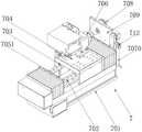
为实现上述目的,本发明提供如下技术方案:一种八轴高精度数控工具外圆磨床,该外圆磨床包括支撑座、磨床底座和工作台;所述支撑座上设置有磨床底座,所述磨床底座上设置有工作台,所述工作台上设置有进给机构,所述进给机构用于将待加工工件进行夹取,并将待加工工件进给至加工位,所述工作台还设置有三轴移载机构和托盘,所述三轴移载机构为现有机构,实现对待加工工件在X轴、Y轴和Z轴上的移载,所述三轴移载机构末端设置有机械手,所述机械手对托盘上的待加工工件进行夹取,利用三轴移载机构将机械手抓取的待加工工件移载至进给机构,所述工作台上还设置有第一打磨机构和第二打磨机构,所述第一打磨机构和第二打磨机构为现有机构,利用电机驱动砂轮对进给机构上的待加工工件进行打磨和加工。In order to achieve the above purpose, the present invention provides the following technical solutions: an eight-axis high-precision CNC tool cylindrical grinder, the cylindrical grinder includes a support seat, a grinder base and a workbench; the support seat is provided with a grinder base, and the The grinding machine base is provided with a worktable, and a feeding mechanism is provided on the worktable, and the feeding mechanism is used for clamping the workpiece to be processed and feeding the workpiece to be processed to the processing position, and the worktable also A three-axis transfer mechanism and a tray are provided. The three-axis transfer mechanism is an existing mechanism, which realizes the transfer of the workpiece to be processed on the X-axis, Y-axis and Z-axis. The end of the three-axis transfer mechanism is provided with a manipulator. , the manipulator clamps the workpiece to be processed on the pallet, and uses the three-axis transfer mechanism to transfer the workpiece to be processed by the manipulator to the feeding mechanism. The worktable is also provided with a first grinding mechanism and a second grinding mechanism. Two grinding mechanisms, the first grinding mechanism and the second grinding mechanism are existing mechanisms, which use the motor to drive the grinding wheel to grind and process the workpiece to be processed on the feeding mechanism.
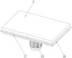
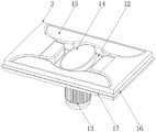
作为优选技术方案,所述磨床底座与工作台之间设置有导流槽,所述导流槽用于对待加工工件打磨过程中产生的碎屑和切屑液进行导流,所述导流槽上还设置有排污口,所述排污口用于对碎屑和切屑液的混合物进行排污处理,所述工作台内部设置有动力空腔,所述磨床底座底端中部设置有驱动电机,所述驱动电机的输出端位于动力空腔内部,所述驱动电机的输出端上设置有驱动轮,所述动力空腔内壁设置有供气气囊,所述供气气囊进气口上设置有只能从外界向供气气囊进气的单向阀,所述供气气囊出气口上还设置有只能从供气气囊向外出气的单向阀,所述工作台侧壁上还设置有吹气孔,所述吹气孔吹出的气体用于对导流槽内部的碎屑和切屑液混合物进行收集,所述供气气囊上的出气口与吹气孔之间通过软管连接,当供气气囊受到驱动轮挤压时,供气气囊内部的气体通过软管被挤压至吹气孔位置处,吹气孔吹出的气体对导流槽中的混合物进行收集,所述工作台外侧设置有导流环,所述导流环用于将待加工工件打磨过程中产生的碎屑和切屑液混合物进行导流引导至导流槽中。As a preferred technical solution, a diversion groove is provided between the grinding machine base and the worktable, and the diversion groove is used to divert the debris and chip liquid generated during the grinding process of the workpiece to be processed. A sewage outlet is also provided, and the sewage outlet is used to perform sewage treatment on the mixture of debris and cutting liquid, a power cavity is arranged inside the worktable, and a driving motor is arranged in the middle of the bottom end of the grinding machine base. The output end of the motor is located inside the power cavity, the output end of the drive motor is provided with a driving wheel, the inner wall of the power cavity is provided with an air supply airbag, and the air supply airbag air inlet is provided with an airbag that can only be sent from the outside. A one-way valve for air intake of the air supply airbag, the air outlet of the air supply airbag is also provided with a one-way valve that can only discharge air from the air supply airbag, the side wall of the workbench is also provided with a blowing hole, the The gas blown from the blowing hole is used to collect the mixture of debris and cutting liquid inside the diversion groove. The air outlet on the air supply airbag and the air blowing hole are connected by a hose. When the air supply airbag is squeezed by the driving wheel When the air bag is pressed, the gas inside the air supply airbag is squeezed to the position of the blowing hole through the hose, and the gas blown from the blowing hole collects the mixture in the diversion groove. The ring is used to guide and guide the mixture of chips and chip fluid generated during the grinding of the workpiece to be machined into the guide groove.
作为优选技术方案,所述吹气孔倾斜设置,目的是为了使得吹气孔吹出的气体可以驱动导流槽中的混合物流动,使得碎屑和切屑液的混合物可以流向排污口进行收集。As a preferred technical solution, the blowing holes are arranged obliquely, so that the gas blown out of the blowing holes can drive the mixture in the diversion groove to flow, so that the mixture of chips and cutting liquid can flow to the sewage outlet for collection.
作为优选技术方案,所述驱动轮为椭圆形,所述驱动轮边部嵌入安装有驱动辊,目的是为了实现对动力空腔中的供气气囊进行间歇性挤压,使得供气气囊可以实现反复性供气。As a preferred technical solution, the driving wheel is elliptical, and a driving roller is embedded in the edge of the driving wheel, in order to achieve intermittent extrusion of the air supply airbag in the power cavity, so that the air supply airbag can realize Repeated gas supply.
作为优选技术方案,所述进给机构包括进给座、滑轨、滑块、移动板、驱动机构、夹持座、挡污机构和打磨轮;As a preferred technical solution, the feeding mechanism includes a feeding seat, a sliding rail, a sliding block, a moving plate, a driving mechanism, a clamping seat, a dirt blocking mechanism and a grinding wheel;
所述进给座设置在工作台上,所述工作台上设置有滑轨,所述滑轨上设置有滑块,所述滑块上设置有移动板,所述移动板上设置有夹持座,所述夹持座用于对待加工工件进行夹持,机械手从托盘上夹取的待加工工件会被移载至夹持座上进行夹持和固定,所述移动板通过驱动机构驱动其在滑轨上移动,所述进给座一端设置有挡污机构,所述挡污机构用于对待加工工件加工打磨过程中产生的碎屑和切屑液混合物进行阻挡,避免混合物污染进给座,所述进给座一端还设置有打磨轮,所述打磨轮用于对待加工工件进行打磨。The feed seat is set on a workbench, a slide rail is set on the workbench, a slide block is set on the slide rail, a moving plate is set on the slide block, and a clamping plate is set on the mobile board The clamping seat is used to clamp the workpiece to be processed. The workpiece to be processed that is clamped by the manipulator from the pallet will be transferred to the clamping seat for clamping and fixing. The moving plate is driven by the driving mechanism. Moving on the slide rail, one end of the feed seat is provided with a dirt blocking mechanism, the dirt blocking mechanism is used to block the mixture of debris and cutting fluid generated during the processing and grinding of the workpiece to be processed, so as to prevent the mixture from contaminating the feeding seat, One end of the feed seat is also provided with a grinding wheel, and the grinding wheel is used for grinding the workpiece to be processed.
作为优选技术方案,所述挡污机构上设置有防污板,所述防污板上设置有插入孔,所述插入孔内部设置有退污板,所述夹持座对待加工工件进行夹持后,通过驱动机构驱动夹持座向防污板位置处移动,使得待加工工件插入插入孔中,然后利用插入孔远离夹持座一侧的打磨轮、第一打磨机构和第二打磨机构对待加工工件进行打磨,待打磨完成后,利用夹持座在滑轨上的移动,将加工完成的工件从插入孔中退出,此时,退污板可以去除待加工工件加工过程中产生的碎屑,加工完成后,利用三轴移载机构驱动机械手从夹持座上将加工完成的工件取下,并移载至另一个托盘上进行存放,所述防污板上还设置有切屑液管道,用于为待加工工件的加工提供切屑液。As a preferred technical solution, an anti-fouling plate is arranged on the anti-fouling mechanism, an insertion hole is arranged on the anti-fouling plate, and a decontamination plate is arranged inside the insertion hole, and the clamping seat clamps the workpiece to be processed. Then, drive the clamping seat to move to the position of the anti-fouling plate through the driving mechanism, so that the workpiece to be processed is inserted into the insertion hole, and then use the grinding wheel, the first grinding mechanism and the second grinding mechanism on the side of the insertion hole away from the clamping seat to treat the workpiece. The processed workpiece is ground. After the grinding is completed, the processed workpiece is withdrawn from the insertion hole by the movement of the clamping seat on the slide rail. At this time, the decontamination plate can remove the debris generated during the processing of the workpiece to be processed. After the processing is completed, the three-axis transfer mechanism is used to drive the manipulator to remove the processed workpiece from the clamping seat, and transfer it to another tray for storage. The anti-fouling plate is also provided with a chip liquid pipeline. Used to provide chip fluid for the machining of workpieces to be machined.
作为优选技术方案,所述驱动机构包括驱动丝杆、驱动块、供气波纹管、吹气软管、吹气口和连动机构;As a preferred technical solution, the driving mechanism includes a driving screw, a driving block, an air supply bellows, an air blowing hose, an air blowing port and a linkage mechanism;
所述进给座内部设置有驱动丝杆,所述驱动丝杆上通过螺纹连接有驱动块,所述驱动块与移动板固定连接,通过驱动丝杆的转动,带动驱动块移动,所述驱动丝杆外侧远离挡污机构一侧设置有供气波纹管,所述供气波纹管上设置有吹气软管,使得驱动块在驱动丝杆上的移动可以对供气波纹管进行挤压,所述挡污机构上设置有吹气口,所述吹气口与吹气软管连接,当驱动块在驱动丝杆上移动,将加工完成的工件退出时,驱动块会对供气波纹管进行挤压,使得供气波纹管内部的气体通过吹气口吹出,使得当待加工工件退出时,可以对加工后粘连在挡污机构上的混合物进行处理,所述驱动块上还设置有连动机构,所述连动机构可以在驱动块移动时,使得吹气口伸出挡污机构。A drive screw rod is arranged inside the feed seat, a drive block is connected to the drive screw rod through a screw thread, and the drive block is fixedly connected with the moving plate. The rotation of the drive screw rod drives the drive block to move, and the An air supply bellows is arranged on the outer side of the screw rod away from the dirt blocking mechanism, and an air blowing hose is arranged on the air supply bellows, so that the movement of the driving block on the driving screw rod can squeeze the air supply bellows. The dirt blocking mechanism is provided with an air blowing port, and the air blowing port is connected with the air blowing hose. When the driving block moves on the driving screw rod to withdraw the processed workpiece, the driving block will squeeze the air supply bellows. pressure, so that the gas inside the air supply bellows is blown out through the air blowing port, so that when the workpiece to be processed exits, the mixture adhering to the dirt blocking mechanism after processing can be processed. The driving block is also provided with a linkage mechanism, The linkage mechanism can cause the blowing port to extend out of the dirt blocking mechanism when the driving block moves.
作为优选技术方案,所述连动机构包括第一连动板、第二连动板、连动凸起、连动滑孔和复位弹簧;As a preferred technical solution, the interlocking mechanism includes a first interlocking plate, a second interlocking plate, a interlocking protrusion, a interlocking sliding hole and a return spring;
所述第一连动板与第二连动板相互卡合,所述第一连动板与第二连动板之间设置有复位弹簧,以保证第二连动板从第一连动板内部伸出,所述驱动块上开设有连动滑孔,所述第一连动板和第二连动板穿过连动滑孔,所述第一连动板和第二连动板靠近供气波纹管位置处设置有连动凸起,当驱动块在驱动丝杆上移动时,第一连动板和第二连动板会在连动滑孔内部滑动,当连动滑孔移动至连动凸起处时,会驱动第二连动板收入第一连动板中。The first interlocking plate and the second interlocking plate are engaged with each other, and a return spring is arranged between the first interlocking plate and the second interlocking plate to ensure that the second interlocking plate is removed from the first interlocking plate. The inside is extended, the driving block is provided with a linkage sliding hole, the first linkage plate and the second linkage plate pass through the linkage sliding hole, and the first linkage plate and the second linkage plate are close to each other. There is a linkage protrusion at the position of the air supply bellows. When the drive block moves on the drive screw, the first linkage plate and the second linkage plate will slide inside the linkage sliding hole. When the linkage sliding hole moves When reaching the interlocking protrusion, the second interlocking plate is driven to be received into the first interlocking plate.
作为优选技术方案,所述挡污机构包括支撑挡板、窗口挡板、连杆、弹性金属片、固定环和变向辊;As a preferred technical solution, the dirt blocking mechanism includes a support baffle, a window baffle, a connecting rod, an elastic metal sheet, a fixing ring and a direction changing roller;
所述支撑挡板位于进给座一端,所述支撑挡板上开设有窗口,所述窗口上设置有窗口挡板,所述窗口挡板与第一连动板和第二连动板之间通过连杆连接,当第二连动板和第一连动板在连动滑孔中移动时,会使得第二连动板收入第一连动板中,进而在连杆的作用下带动窗口挡板移动,使得窗口打开,所述窗口挡板一端设置有弹性金属片,所述弹性金属片一端设置有固定环,所述固定环用于对吹气口进行固定,所述弹性金属片与窗口挡板连接位置处设置有变向辊,当窗口挡板在连杆作用下移动时,变向辊会对弹性金属片进行挤压,驱动吹气口从支撑挡板内部伸出,进而配合驱动块对供气波纹管进行挤压,使得气体可以通过吹气口吹出,对支撑挡板上的碎屑和切屑液混合物进行处理。The support baffle is located at one end of the feed seat, a window is opened on the support baffle, a window baffle is arranged on the window, and the window baffle is connected to the first interlocking plate and the second interlocking plate. Through the connection of the connecting rod, when the second linking plate and the first linking plate move in the linking sliding hole, the second linking plate will be received into the first linking plate, and then the window shutter will be driven under the action of the connecting rod. The plate moves to open the window. One end of the window baffle is provided with an elastic metal sheet, and one end of the elastic metal sheet is provided with a fixing ring. The fixing ring is used to fix the blowing port. A direction-changing roller is arranged at the connecting position of the plate. When the window baffle moves under the action of the connecting rod, the direction-changing roller will squeeze the elastic metal sheet, and drive the blowing port to protrude from the inside of the supporting baffle, and then cooperate with the driving block to The air supply bellows is squeezed so that the air can be blown out through the air blowing port to treat the mixture of chips and cutting liquid on the support baffle.
作为优选技术方案,所述弹性金属片与窗口挡板之间的夹角为0°-30°,目的是为了使得当窗口挡板移动时,变向辊会对弹性金属片进行挤压,随着窗口挡板的不断移动,吹气口逐渐从支撑挡板伸出。As a preferred technical solution, the included angle between the elastic metal sheet and the window baffle is 0°-30°, so that when the window baffle moves, the direction changing roller will squeeze the elastic metal sheet, and the With the continuous movement of the window shutter, the blowing port gradually protrudes from the supporting shutter.
与现有技术相比,本发明的有益效果是:Compared with the prior art, the beneficial effects of the present invention are:
1、本发明设置有进给机构、三轴移载机构和机械手,使得可以实现对待加工工件的自动化上料,自动化程度高,精度更高,提高了对工件加工的效率,同时,提高了成品率。1. The present invention is provided with a feeding mechanism, a three-axis transfer mechanism and a manipulator, so that the automatic feeding of the workpiece to be processed can be realized, the degree of automation is high, the precision is higher, the processing efficiency of the workpiece is improved, and at the same time, the finished product is improved. Rate.
2、本发明设置有挡污机构,使得可以对工件加工过程中产生的碎屑和切屑液的混合物进行阻挡,避免影响进给机构对工件的正常进给,同时,在防污板、插入孔和退污板的作用下,可以避免工件在加工过程中以及加工完成之后,工件表面粘连碎屑,保证了加工之后的工件的洁净程度。2. The present invention is provided with a dirt blocking mechanism, which can block the mixture of debris and cutting fluid generated during the processing of the workpiece, so as to avoid affecting the normal feeding of the workpiece by the feeding mechanism. And under the action of the decontamination plate, the workpiece surface can be prevented from adhering to debris during and after processing, which ensures the cleanliness of the workpiece after processing.
3、本发明设置有连动机构和挡污机构,通过连动机构,在供气波纹管供气的过程中,可以控制窗口挡板自动打开,使得吹气口从窗口伸出,对支撑挡板上的碎屑进行清理,避免碎屑粘连,影响使用,同时,在对工件进行加工的过程中,可以利用窗口挡板对窗口进行封闭,避免碎屑等进入支撑挡板内部。3. The present invention is provided with a linkage mechanism and a dirt blocking mechanism. Through the linkage mechanism, during the air supply process of the air supply bellows, the window baffle can be controlled to automatically open, so that the air blowing port extends from the window, and the support baffle is blocked. The debris on the surface is cleaned to prevent debris from sticking and affecting the use. At the same time, during the processing of the workpiece, the window baffle can be used to seal the window to prevent debris from entering the support baffle.
4、本发明设置有弹性金属片和变向辊,使得窗口挡板移动的过程中,可以驱使弹性金属片发生移动和方向的改变,使得固定有吹气口的固定环从窗口伸出,实现了一定的联动性。4. The present invention is provided with an elastic metal sheet and a direction-changing roller, so that during the movement of the window baffle, the elastic metal sheet can be driven to move and change its direction, so that the fixing ring fixed with the blowing port extends from the window, realizing the some linkage.
附图说明Description of drawings
图1为本发明一种八轴高精度数控工具外圆磨床的结构示意图;Fig. 1 is a structural schematic diagram of an eight-axis high-precision CNC tool cylindrical grinder according to the present invention;
图2为本发明一种八轴高精度数控工具外圆磨床中进给机构的结构示意图;2 is a schematic structural diagram of a feeding mechanism in an eight-axis high-precision CNC tool cylindrical grinder according to the present invention;
图3为本发明一种八轴高精度数控工具外圆磨床中磨床底座的结构示意图;3 is a schematic structural diagram of a grinder base in an eight-axis high-precision CNC tool cylindrical grinder according to the present invention;
图4为本发明一种八轴高精度数控工具外圆磨床中工作台的结构示意图;4 is a schematic structural diagram of a worktable in an eight-axis high-precision CNC tool cylindrical grinder according to the present invention;
图5为本发明一种八轴高精度数控工具外圆磨床中工作台内部的结构示意图;FIG. 5 is a schematic structural diagram of the interior of a worktable in an eight-axis high-precision CNC tool cylindrical grinder according to the present invention;
图6为本发明一种八轴高精度数控工具外圆磨床中驱动机构的结构示意图;6 is a schematic structural diagram of a drive mechanism in an eight-axis high-precision CNC tool cylindrical grinder according to the present invention;
图7为本发明一种八轴高精度数控工具外圆磨床中连动机构的结构示意图;7 is a schematic structural diagram of a linkage mechanism in an eight-axis high-precision CNC tool cylindrical grinder according to the present invention;
图8为本发明一种八轴高精度数控工具外圆磨床中挡污机构的结构示意图;8 is a schematic structural diagram of a dirt blocking mechanism in an eight-axis high-precision CNC tool cylindrical grinder according to the present invention;
图9为本发明一种八轴高精度数控工具外圆磨床中驱动块的结构示意图;9 is a schematic structural diagram of a drive block in an eight-axis high-precision CNC tool cylindrical grinder according to the present invention;
图10为本发明一种八轴高精度数控工具外圆磨床中复位弹簧的安装位置示意图;10 is a schematic diagram of the installation position of the return spring in an eight-axis high-precision CNC tool cylindrical grinder according to the present invention;
图中标号:1、支撑座;2、磨床底座;3、工作台;4、三轴移载机构;5、机械手;6、托盘;Labels in the figure: 1. Support seat; 2. Grinder base; 3. Worktable; 4. Three-axis transfer mechanism; 5. Robot arm; 6. Pallet;
7、进给机构;701、进给座;702、滑轨;703、滑块;704、移动板;705、驱动机构;7051、驱动丝杆;7052、驱动块;7053、供气波纹管;7054、吹气软管;7055、吹气口;70561、第一连动板;70562、第二连动板;70563、连动凸起;70564、连动滑孔;70565、复位弹簧;706、夹持座;707、挡污机构;7070、支撑挡板;7071、窗口挡板;7072、连杆;7073、弹性金属片;7074、固定环;7075、变向辊;708、打磨轮;709、防污板;710、插入孔;711、退污板;712、切屑液管道;7. Feeding mechanism; 701, Feeding seat; 702, Slide rail; 703, Slider; 704, Moving plate; 705, Driving mechanism; 7051, Driving screw; 7052, Driving block; 7053, Air supply bellows; 7054, blowing hose; 7055, blowing port; 70561, first interlocking plate; 70562, second interlocking plate; 70563, interlocking protrusion; 70564, interlocking sliding hole; 70565, return spring; 706, clip Holder; 707, dirt blocking mechanism; 7070, support baffle; 7071, window baffle; 7072, connecting rod; 7073, elastic metal sheet; 7074, fixing ring; 7075, direction changing roller; 708, grinding wheel; 709, Antifouling plate; 710, insertion hole; 711, decontamination plate; 712, cutting fluid pipeline;
8、第一打磨机构;9、第二打磨机构;10、导流槽;11、排污口;12、动力空腔;13、驱动电机;14、驱动轮;15、供气气囊;16、导流环;17、吹气孔。8. The first grinding mechanism; 9. The second grinding mechanism; 10. The diversion groove; 11. The sewage outlet; 12. The power cavity; 13. The driving motor; 14. The driving wheel; Flow ring; 17. Blow hole.
具体实施方式Detailed ways
下面将结合本发明实施例中的附图,对本发明实施例中的技术方案进行清楚、完整地描述,显然,所描述的实施例仅仅是本发明一部分实施例,而不是全部的实施例。基于本发明中的实施例,本领域普通技术人员在没有做出创造性劳动前提下所获得的所有其他实施例,都属于本发明保护的范围。The technical solutions in the embodiments of the present invention will be clearly and completely described below with reference to the accompanying drawings in the embodiments of the present invention. Obviously, the described embodiments are only a part of the embodiments of the present invention, but not all of the embodiments. Based on the embodiments of the present invention, all other embodiments obtained by those of ordinary skill in the art without creative efforts shall fall within the protection scope of the present invention.
实施例:如图1~图10所示,本发明提供以下技术方案,一种八轴高精度数控工具外圆磨床,该外圆磨床包括支撑座1、磨床底座2和工作台3;支撑座1上设置有磨床底座2,磨床底座2上设置有工作台3,工作台3上设置有进给机构7,进给机构7用于将待加工工件进行夹取,并将待加工工件进给至加工位,工作台3还设置有三轴移载机构4和托盘6,三轴移载机构4为现有机构,实现对待加工工件在X轴、Y轴和Z轴上的移载,三轴移载机构4末端设置有机械手5,机械手5对托盘6上的待加工工件进行夹取,利用三轴移载机构4将机械手5抓取的待加工工件移载至进给机构7,工作台3上还设置有第一打磨机构8和第二打磨机构9,第一打磨机构8和第二打磨机构9为现有机构,利用电机驱动砂轮对进给机构7上的待加工工件进行打磨和加工。Example: As shown in Figures 1 to 10, the present invention provides the following technical solutions, an eight-axis high-precision CNC tool cylindrical grinder, the cylindrical grinder includes a support seat 1, a
磨床底座2与工作台3之间设置有导流槽10,导流槽10用于对待加工工件打磨过程中产生的碎屑和切屑液进行导流,导流槽10上还设置有排污口11,排污口11用于对碎屑和切屑液的混合物进行排污处理,工作台3内部设置有动力空腔12,磨床底座2底端中部设置有驱动电机13,驱动电机13的输出端位于动力空腔12内部,驱动电机13的输出端上设置有驱动轮14,动力空腔12内壁设置有供气气囊15,供气气囊15进气口上设置有只能从外界向供气气囊15进气的单向阀,供气气囊15出气口上还设置有只能从供气气囊15向外出气的单向阀,工作台3侧壁上还设置有吹气孔17,吹气孔17吹出的气体用于对导流槽10内部的碎屑和切屑液混合物进行收集,供气气囊15上的出气口与吹气孔17之间通过软管连接,当供气气囊15受到驱动轮14挤压时,供气气囊15内部的气体通过软管被挤压至吹气孔17位置处,吹气孔17吹出的气体对导流槽10中的混合物进行收集,工作台3外侧设置有导流环16,导流环16用于将待加工工件打磨过程中产生的碎屑和切屑液混合物进行导流引导至导流槽10中。A
吹气孔17倾斜设置,目的是为了使得吹气孔17吹出的气体可以驱动导流槽10中的混合物流动,使得碎屑和切屑液的混合物可以流向排污口11进行收集。The blowing holes 17 are arranged obliquely, so that the gas blown out of the blowing holes 17 can drive the mixture in the
驱动轮14为椭圆形,驱动轮14边部嵌入安装有驱动辊,目的是为了实现对动力空腔12中的供气气囊15进行间歇性挤压,使得供气气囊15可以实现反复性供气。The
进给机构7包括进给座701、滑轨702、滑块703、移动板704、驱动机构705、夹持座706、挡污机构707和打磨轮708;The
进给座701设置在工作台3上,工作台3上设置有滑轨702,滑轨702上设置有滑块703,滑块703上设置有移动板704,移动板704上设置有夹持座706,夹持座706用于对待加工工件进行夹持,机械手5从托盘6上夹取的待加工工件会被移载至夹持座706上进行夹持和固定,移动板704通过驱动机构705驱动其在滑轨702上移动,进给座701一端设置有挡污机构707,挡污机构707用于对待加工工件加工打磨过程中产生的碎屑和切屑液混合物进行阻挡,避免混合物污染进给座701,进给座701一端还设置有打磨轮708,打磨轮708用于对待加工工件进行打磨。The
挡污机构707上设置有防污板709,防污板709上设置有插入孔710,插入孔710内部设置有退污板711,夹持座706对待加工工件进行夹持后,通过驱动机构705驱动夹持座706向防污板709位置处移动,使得待加工工件插入插入孔710中,然后利用插入孔710远离夹持座706一侧的打磨轮708、第一打磨机构8和第二打磨机构9对待加工工件进行打磨,待打磨完成后,利用夹持座706在滑轨702上的移动,将加工完成的工件从插入孔710中退出,此时,退污板711可以去除待加工工件加工过程中产生的碎屑,加工完成后,利用三轴移载机构4驱动机械手5从夹持座706上将加工完成的工件取下,并移载至另一个托盘6上进行存放,防污板709上还设置有切屑液管道712,用于为待加工工件的加工提供切屑液。The
驱动机构705包括驱动丝杆7051、驱动块7052、供气波纹管7053、吹气软管7054、吹气口7055和连动机构;The
进给座701内部设置有驱动丝杆7051,驱动丝杆7051上通过螺纹连接有驱动块7052,驱动块7052与移动板704固定连接,通过驱动丝杆7051的转动,带动驱动块7052移动,驱动丝杆7051外侧远离挡污机构707一侧设置有供气波纹管7053,供气波纹管7053上设置有吹气软管7054,使得驱动块7052在驱动丝杆7051上的移动可以对供气波纹管7053进行挤压,挡污机构707上设置有吹气口7055,吹气口7055与吹气软管7054连接,当驱动块7052在驱动丝杆7051上移动,将加工完成的工件退出时,驱动块7052会对供气波纹管7053进行挤压,使得供气波纹管7053内部的气体通过吹气口7055吹出,使得当待加工工件退出时,可以对加工后粘连在挡污机构707上的混合物进行处理,驱动块7052上还设置有连动机构,连动机构可以在驱动块7052移动时,使得吹气口7055伸出挡污机构707。A driving
连动机构包括第一连动板70561、第二连动板70562、连动凸起70563、连动滑孔70564和复位弹簧70565;The linkage mechanism includes a
第一连动板70561与第二连动板70562相互卡合,第一连动板70561与第二连动板70562之间设置有复位弹簧70565,以保证第二连动板70562从第一连动板70561内部伸出,驱动块7052上开设有连动滑孔70564,第一连动板70561和第二连动板70562穿过连动滑孔70564,第一连动板70561和第二连动板70562靠近供气波纹管7053位置处设置有连动凸起70563,当驱动块7052在驱动丝杆7051上移动时,第一连动板70561和第二连动板70562会在连动滑孔70564内部滑动,当连动滑孔70564移动至连动凸起70563处时,会驱动第二连动板70562收入第一连动板70561中。The
挡污机构707包括支撑挡板7070、窗口挡板7071、连杆7072、弹性金属片7073、固定环7074和变向辊7075;The
支撑挡板7070位于进给座701一端,支撑挡板7070上开设有窗口,窗口上设置有窗口挡板7071,窗口挡板7071与第一连动板70561和第二连动板70562之间通过连杆7072连接,当第二连动板70562和第一连动板70561在连动滑孔70564中移动时,会使得第二连动板70562收入第一连动板70561中,进而在连杆7072的作用下带动窗口挡板7071移动,使得窗口打开,窗口挡板7071一端设置有弹性金属片7073,弹性金属片7073一端设置有固定环7074,固定环7074用于对吹气口7055进行固定,弹性金属片7073与窗口挡板7071连接位置处设置有变向辊7075,当窗口挡板7071在连杆7072作用下移动时,变向辊7075会对弹性金属片7073进行挤压,驱动吹气口7055从支撑挡板7070内部伸出,进而配合驱动块7052对供气波纹管7053进行挤压,使得气体可以通过吹气口7055吹出,对支撑挡板7070上的碎屑和切屑液混合物进行处理。The
弹性金属片7073与窗口挡板7071之间的夹角为0°-30°,目的是为了使得当窗口挡板7071移动时,变向辊7075会对弹性金属片7073进行挤压,随着窗口挡板7071的不断移动,吹气口7055逐渐从支撑挡板7070伸出。The included angle between the
本发明的工作原理是:在使用时,首先通过三轴移载机构4控制机械手5移动,利用机械手5对托盘6上的待加工工件进行抓取,并将抓取之后的工件移载至夹持座706位置处,利用夹持座706对待加工工件进行夹持,随后通过驱动机构705中的驱动丝杆7051带动驱动块7052移动,进而使得夹持座706向防污板709位置处移动,此时,被夹持座706夹持的待加工工件会插入插入孔710中,待工件完全固定之后,利用打磨轮708、第一打磨机构8和第二打磨机构9对待加工工件进行打磨和加工,在加工过程中,利用切屑液管道712喷洒切屑液,保证加工过程中的工件的稳定性以及防止碎屑的飞溅;The working principle of the present invention is as follows: when in use, first control the movement of the manipulator 5 through the three-
待工件加工完成之后,利用驱动丝杆7051驱动夹持座706退回,在夹持座706退回的过程中,可以利用退污板711对工件加工过程中产生的碎屑进行清理,保证加工之后的工件表面洁净,在驱动块7052控制夹持座706退回的过程中,第一连动板70561和第二连动板70562会在连动滑孔70564内部滑动,当随着驱动块7052的不断移动,会对供气波纹管7053造成挤压,同时,连动凸起70563会滑动至连动滑孔70564位置处,此时,第二连动板70562收入第一连动板70561内部,进而通过连杆7072带动窗口挡板7071移动,在窗口挡板7071移动的过程中,窗口被打开,同时,弹性金属片7073在变向辊7075的作用下,慢慢的发生形变,直至固定有吹气口7055的固定环7074从窗口中伸出,此时,供气波纹管7053也完全受到挤压,供气波纹管7053内部的气体通过吹气软管7054输送至吹气口7055位置处,此时,利用吹气口7055可以对支撑挡板7070表面粘连的碎屑进行清理,当夹持座706再次向防污板709位置处移动时,吹气口7055会再次收入支撑挡板7070中,窗口挡板7071也会对窗口进行封闭,避免碎屑进入支撑挡板7070中;After the workpiece is processed, the driving
碎屑会在导流槽10中被收集,此时,通过控制驱动电机13,带动驱动轮14转动,椭圆形的驱动轮14会间接性的对供气气囊15进行挤压,此时,供气气囊15被挤压处的气体通过吹气孔17吹出,对导流槽10中的碎屑和切屑液的混合物进行吹动,使得混合物向排污口11位置处移动,此时,碎屑和切屑液的混合被会收集统一处理。The debris will be collected in the
对于本领域技术人员而言,显然本发明不限于上述示范性实施例的细节,而且在不背离本发明的精神或基本特征的情况下,能够以其他的具体形式实现本发明。因此,无论从哪一点来看,均应将实施例看作是示范性的,而且是非限制性的,本发明的范围由所附权利要求而不是上述说明限定,因此旨在将落在权利要求的等同要件的含义和范围内的所有变化囊括在本发明内。不应将权利要求中的任何附图标记视为限制所涉及的权利要求。It will be apparent to those skilled in the art that the present invention is not limited to the details of the above-described exemplary embodiments, but that the present invention may be embodied in other specific forms without departing from the spirit or essential characteristics of the invention. Therefore, the embodiments are to be regarded in all respects as illustrative and not restrictive, and the scope of the invention is to be defined by the appended claims rather than the foregoing description, which are therefore intended to fall within the scope of the claims. All changes within the meaning and scope of the equivalents of , are included in the present invention. Any reference signs in the claims shall not be construed as limiting the involved claim.
Claims (10)
Priority Applications (1)
| Application Number | Priority Date | Filing Date | Title |
|---|---|---|---|
| CN202210203078.8ACN114536118B (en) | 2022-03-02 | 2022-03-02 | An eight-axis high-precision CNC tool cylindrical grinder |
Applications Claiming Priority (1)
| Application Number | Priority Date | Filing Date | Title |
|---|---|---|---|
| CN202210203078.8ACN114536118B (en) | 2022-03-02 | 2022-03-02 | An eight-axis high-precision CNC tool cylindrical grinder |
Publications (2)
| Publication Number | Publication Date |
|---|---|
| CN114536118Atrue CN114536118A (en) | 2022-05-27 |
| CN114536118B CN114536118B (en) | 2022-10-14 |
Family
ID=81660835
Family Applications (1)
| Application Number | Title | Priority Date | Filing Date |
|---|---|---|---|
| CN202210203078.8AActiveCN114536118B (en) | 2022-03-02 | 2022-03-02 | An eight-axis high-precision CNC tool cylindrical grinder |
Country Status (1)
| Country | Link |
|---|---|
| CN (1) | CN114536118B (en) |
Citations (21)
| Publication number | Priority date | Publication date | Assignee | Title |
|---|---|---|---|---|
| US20130273811A1 (en)* | 2012-04-16 | 2013-10-17 | Mori Seiki USA | Grind Hardening Method and Apparatus |
| CN106493641A (en)* | 2016-12-27 | 2017-03-15 | 黄石成大精密机械制造有限公司 | A kind of detachable dust arrester for rounding in metal pipe material |
| CN206780100U (en)* | 2017-05-17 | 2017-12-22 | 冯吉 | Metro pantograph carbon slipper profiling sanding apparatus |
| CN206855212U (en)* | 2017-07-10 | 2018-01-09 | 象山鹿林生物科技有限公司 | Derusting device for iron plate |
| CN108296891A (en)* | 2018-01-10 | 2018-07-20 | 宁波海蔓汽车科技有限公司 | Auto-parts grinding device |
| KR101902695B1 (en)* | 2017-04-12 | 2018-09-28 | 김동현 | Polishing device for kettle bottle |
| CN208496546U (en)* | 2018-06-19 | 2019-02-15 | 厦门创云精智机械设备股份有限公司 | A kind of high precision digital control cylindrical grinding machine |
| CN109366331A (en)* | 2018-09-28 | 2019-02-22 | 庄筱琳 | With the tree ring sample burnishing device of cutter and convex-surface type emery wheel stage scraped finish |
| JP2019181584A (en)* | 2018-04-03 | 2019-10-24 | 株式会社ディスコ | Processing device |
| WO2019206379A1 (en)* | 2018-04-23 | 2019-10-31 | Apparate- und Behälterbau Weller GmbH | Device for cleaning depressions in workpieces |
| CN209700976U (en)* | 2019-03-29 | 2019-11-29 | 长沙航空职业技术学院 | A kind of aircraft appearance cleans automobile-used cleaning device |
| CN110523719A (en)* | 2019-09-06 | 2019-12-03 | 温州实事传媒有限公司 | A kind of saving heavy duty detergent PPR pipe road cleaning device for inner wall |
| CN210649932U (en)* | 2019-09-30 | 2020-06-02 | 天津兴起工贸有限公司 | Frock is used in automobile sleeve processing |
| CN111604765A (en)* | 2020-06-16 | 2020-09-01 | 枣庄科技职业学院 | Sensor shell processing device is taken to thing networking information |
| CN211414824U (en)* | 2020-01-02 | 2020-09-04 | 青岛联诚宏达轨道交通设备有限公司 | Aluminum alloy is polished and is used collection dirt environmental protection casing |
| CN211516944U (en)* | 2017-10-01 | 2020-09-18 | 浦江县宏创科技开发有限公司 | Polishing device for improving cleanliness of workpiece surface |
| CN212329148U (en)* | 2020-05-06 | 2021-01-12 | 赣州市福牛金属制品有限公司 | Automatic galvanized pipe metal filing blowing device |
| CN112428117A (en)* | 2020-10-20 | 2021-03-02 | 罗峰 | Steel pipe rust cleaning device that polishes |
| CN112775735A (en)* | 2020-12-31 | 2021-05-11 | 李宗权 | Waste metal pipe inner wall grinding device |
| CN215317819U (en)* | 2021-08-12 | 2021-12-28 | 浙江杰克机床股份有限公司 | Combined grinding machine for shaft workpieces |
| CN215830254U (en)* | 2021-08-12 | 2022-02-15 | 安徽金安装饰工程有限公司 | Magnetic attraction device in door and window frame sill of aluminum-wood composite door and window |
- 2022
- 2022-03-02CNCN202210203078.8Apatent/CN114536118B/enactiveActive
Patent Citations (21)
| Publication number | Priority date | Publication date | Assignee | Title |
|---|---|---|---|---|
| US20130273811A1 (en)* | 2012-04-16 | 2013-10-17 | Mori Seiki USA | Grind Hardening Method and Apparatus |
| CN106493641A (en)* | 2016-12-27 | 2017-03-15 | 黄石成大精密机械制造有限公司 | A kind of detachable dust arrester for rounding in metal pipe material |
| KR101902695B1 (en)* | 2017-04-12 | 2018-09-28 | 김동현 | Polishing device for kettle bottle |
| CN206780100U (en)* | 2017-05-17 | 2017-12-22 | 冯吉 | Metro pantograph carbon slipper profiling sanding apparatus |
| CN206855212U (en)* | 2017-07-10 | 2018-01-09 | 象山鹿林生物科技有限公司 | Derusting device for iron plate |
| CN211516944U (en)* | 2017-10-01 | 2020-09-18 | 浦江县宏创科技开发有限公司 | Polishing device for improving cleanliness of workpiece surface |
| CN108296891A (en)* | 2018-01-10 | 2018-07-20 | 宁波海蔓汽车科技有限公司 | Auto-parts grinding device |
| JP2019181584A (en)* | 2018-04-03 | 2019-10-24 | 株式会社ディスコ | Processing device |
| WO2019206379A1 (en)* | 2018-04-23 | 2019-10-31 | Apparate- und Behälterbau Weller GmbH | Device for cleaning depressions in workpieces |
| CN208496546U (en)* | 2018-06-19 | 2019-02-15 | 厦门创云精智机械设备股份有限公司 | A kind of high precision digital control cylindrical grinding machine |
| CN109366331A (en)* | 2018-09-28 | 2019-02-22 | 庄筱琳 | With the tree ring sample burnishing device of cutter and convex-surface type emery wheel stage scraped finish |
| CN209700976U (en)* | 2019-03-29 | 2019-11-29 | 长沙航空职业技术学院 | A kind of aircraft appearance cleans automobile-used cleaning device |
| CN110523719A (en)* | 2019-09-06 | 2019-12-03 | 温州实事传媒有限公司 | A kind of saving heavy duty detergent PPR pipe road cleaning device for inner wall |
| CN210649932U (en)* | 2019-09-30 | 2020-06-02 | 天津兴起工贸有限公司 | Frock is used in automobile sleeve processing |
| CN211414824U (en)* | 2020-01-02 | 2020-09-04 | 青岛联诚宏达轨道交通设备有限公司 | Aluminum alloy is polished and is used collection dirt environmental protection casing |
| CN212329148U (en)* | 2020-05-06 | 2021-01-12 | 赣州市福牛金属制品有限公司 | Automatic galvanized pipe metal filing blowing device |
| CN111604765A (en)* | 2020-06-16 | 2020-09-01 | 枣庄科技职业学院 | Sensor shell processing device is taken to thing networking information |
| CN112428117A (en)* | 2020-10-20 | 2021-03-02 | 罗峰 | Steel pipe rust cleaning device that polishes |
| CN112775735A (en)* | 2020-12-31 | 2021-05-11 | 李宗权 | Waste metal pipe inner wall grinding device |
| CN215317819U (en)* | 2021-08-12 | 2021-12-28 | 浙江杰克机床股份有限公司 | Combined grinding machine for shaft workpieces |
| CN215830254U (en)* | 2021-08-12 | 2022-02-15 | 安徽金安装饰工程有限公司 | Magnetic attraction device in door and window frame sill of aluminum-wood composite door and window |
Also Published As
| Publication number | Publication date |
|---|---|
| CN114536118B (en) | 2022-10-14 |
Similar Documents
| Publication | Publication Date | Title |
|---|---|---|
| CN212421825U (en) | Full-automatic cutting and cleaning integrated machine for wafer | |
| CN109014275B (en) | Drilling machine | |
| CN116748939A (en) | Numerical control machine tool for cleaning scraps in real time during machining of cutting parts | |
| CN114799987A (en) | Chain type tool magazine of numerical control machining center | |
| CN114536118B (en) | An eight-axis high-precision CNC tool cylindrical grinder | |
| CN221088233U (en) | Chip removal device for numerical control machine tool | |
| CN221676667U (en) | A shaft workpiece processing equipment | |
| CN209887269U (en) | Automatic production line for polishing 3C products | |
| CN220561207U (en) | Accessory grinding device for auto-parts processing | |
| CN117140169A (en) | A CNC machine tool protection mechanism | |
| CN215615122U (en) | Automatic unloading mechanism of hydraulic machine tool | |
| CN114406786A (en) | Air blowing chip removing method for metal cutting | |
| CN221232341U (en) | Positioning device for coordinate grinder | |
| CN220094087U (en) | A dust removal type deburring device | |
| CN218284522U (en) | Horizontal machining center | |
| CN218081948U (en) | Grinding device for machining metal valve accessories | |
| CN222873842U (en) | Multi-station machining machine tool | |
| CN223339092U (en) | A grinding machine for valve faucet processing | |
| CN206105603U (en) | Full -automatic sapphire grinds machine | |
| CN216442838U (en) | A kind of graphite workpiece processing lathe | |
| CN221696159U (en) | Automatic feeding and discharging processing equipment | |
| CN221676689U (en) | A CNC burr cleaning device | |
| CN222537087U (en) | A device for recycling cutting fluid in mechanical processing | |
| CN214212949U (en) | Horizontal three-coordinate numerical control equipment | |
| CN212525171U (en) | Cleaning device for grinding center |
Legal Events
| Date | Code | Title | Description |
|---|---|---|---|
| PB01 | Publication | ||
| PB01 | Publication | ||
| SE01 | Entry into force of request for substantive examination | ||
| SE01 | Entry into force of request for substantive examination | ||
| GR01 | Patent grant | ||
| GR01 | Patent grant | ||
| PE01 | Entry into force of the registration of the contract for pledge of patent right | ||
| PE01 | Entry into force of the registration of the contract for pledge of patent right | Denomination of invention:An 8-axis high-precision CNC tool cylindrical grinder Effective date of registration:20230112 Granted publication date:20221014 Pledgee:Ping An Bank Co.,Ltd. Dongguan Branch Pledgor:DONGGUAN QIANDAO MACHINERY MANUFACTURING Co.,Ltd. Registration number:Y2023980030961 | |
| PC01 | Cancellation of the registration of the contract for pledge of patent right | Granted publication date:20221014 Pledgee:Ping An Bank Co.,Ltd. Dongguan Branch Pledgor:DONGGUAN QIANDAO MACHINERY MANUFACTURING Co.,Ltd. Registration number:Y2023980030961 | |
| PC01 | Cancellation of the registration of the contract for pledge of patent right | ||
| TR01 | Transfer of patent right | Effective date of registration:20241122 Address after:No. 16, Phase I Project of Zhongnan High tech Zhuzhou Intelligent Manufacturing Industrial Park, No. 329 Xinma West Road, Majiahe Street, Tianyuan District, Zhuzhou City, Hunan Province, 412000 Patentee after:Hunan Qiandao Intelligent Technology Co.,Ltd. Country or region after:China Address before:523000 No. 6, Yongsheng East Road, yongtou community, Chang'an Town, Dongguan City, Guangdong Province Patentee before:DONGGUAN QIANDAO MACHINERY MANUFACTURING Co.,Ltd. Country or region before:China | |
| TR01 | Transfer of patent right | ||
| TR01 | Transfer of patent right | Effective date of registration:20250319 Address after:Room 105, Building 4, No. 74 Zhen'an East Road, Chang'an Town, Dongguan City, Guangdong Province, 523000 Patentee after:DONGGUAN QIANDAO MACHINERY MANUFACTURING Co.,Ltd. Country or region after:China Address before:No. 16, Phase I Project of Zhongnan High tech Zhuzhou Intelligent Manufacturing Industrial Park, No. 329 Xinma West Road, Majiahe Street, Tianyuan District, Zhuzhou City, Hunan Province, 412000 Patentee before:Hunan Qiandao Intelligent Technology Co.,Ltd. Country or region before:China | |
| TR01 | Transfer of patent right |