CN114533268A - Sterile adapter and power output part - Google Patents
Sterile adapter and power output partDownload PDFInfo
- Publication number
- CN114533268A CN114533268ACN202111067837.4ACN202111067837ACN114533268ACN 114533268 ACN114533268 ACN 114533268ACN 202111067837 ACN202111067837 ACN 202111067837ACN 114533268 ACN114533268 ACN 114533268A
- Authority
- CN
- China
- Prior art keywords
- sterile adapter
- release switch
- groove
- spring
- spline sleeve
- Prior art date
- Legal status (The legal status is an assumption and is not a legal conclusion. Google has not performed a legal analysis and makes no representation as to the accuracy of the status listed.)
- Pending
Links
- 238000003825pressingMethods0.000claimsabstractdescription54
- 230000002401inhibitory effectEffects0.000claimsdescription46
- 230000009471actionEffects0.000claimsdescription40
- 210000000078clawAnatomy0.000claimsdescription37
- 238000009434installationMethods0.000claimsdescription28
- 239000003638chemical reducing agentSubstances0.000claimsdescription16
- 238000001356surgical procedureMethods0.000claimsdescription15
- 238000005520cutting processMethods0.000claimsdescription11
- 230000000452restraining effectEffects0.000claimsdescription11
- 230000005540biological transmissionEffects0.000claimsdescription10
- 210000005069earsAnatomy0.000claimsdescription6
- 230000000670limiting effectEffects0.000claimsdescription3
- 239000000463materialSubstances0.000claimsdescription3
- 230000006835compressionEffects0.000claimsdescription2
- 238000007906compressionMethods0.000claimsdescription2
- 230000000694effectsEffects0.000claimsdescription2
- 241000894006BacteriaSpecies0.000claims1
- 230000001580bacterial effectEffects0.000claims1
- 238000000926separation methodMethods0.000claims1
- 238000002324minimally invasive surgeryMethods0.000abstractdescription4
- 238000010586diagramMethods0.000description26
- 238000000034methodMethods0.000description4
- 230000036961partial effectEffects0.000description3
- 230000004888barrier functionEffects0.000description2
- 230000008859changeEffects0.000description2
- 230000005764inhibitory processEffects0.000description2
- 238000002360preparation methodMethods0.000description2
- 230000000284resting effectEffects0.000description2
- 230000015572biosynthetic processEffects0.000description1
- 239000008280bloodSubstances0.000description1
- 210000004369bloodAnatomy0.000description1
- 238000007796conventional methodMethods0.000description1
- 238000011161developmentMethods0.000description1
- 238000005516engineering processMethods0.000description1
- 238000007373indentationMethods0.000description1
- 238000003780insertionMethods0.000description1
- 230000037431insertionEffects0.000description1
- 238000004519manufacturing processMethods0.000description1
- 238000012978minimally invasive surgical procedureMethods0.000description1
- 238000012986modificationMethods0.000description1
- 230000004048modificationEffects0.000description1
- 210000000056organAnatomy0.000description1
- 230000036316preloadEffects0.000description1
- 238000011084recoveryMethods0.000description1
- 238000004904shorteningMethods0.000description1
- 230000003068static effectEffects0.000description1
Images


Classifications
- A—HUMAN NECESSITIES
- A61—MEDICAL OR VETERINARY SCIENCE; HYGIENE
- A61B—DIAGNOSIS; SURGERY; IDENTIFICATION
- A61B34/00—Computer-aided surgery; Manipulators or robots specially adapted for use in surgery
- A61B34/30—Surgical robots
- A—HUMAN NECESSITIES
- A61—MEDICAL OR VETERINARY SCIENCE; HYGIENE
- A61B—DIAGNOSIS; SURGERY; IDENTIFICATION
- A61B90/00—Instruments, implements or accessories specially adapted for surgery or diagnosis and not covered by any of the groups A61B1/00 - A61B50/00, e.g. for luxation treatment or for protecting wound edges
- A61B90/40—Apparatus fixed or close to patients specially adapted for providing an aseptic surgical environment
- F—MECHANICAL ENGINEERING; LIGHTING; HEATING; WEAPONS; BLASTING
- F16—ENGINEERING ELEMENTS AND UNITS; GENERAL MEASURES FOR PRODUCING AND MAINTAINING EFFECTIVE FUNCTIONING OF MACHINES OR INSTALLATIONS; THERMAL INSULATION IN GENERAL
- F16D—COUPLINGS FOR TRANSMITTING ROTATION; CLUTCHES; BRAKES
- F16D3/00—Yielding couplings, i.e. with means permitting movement between the connected parts during the drive
- F16D3/02—Yielding couplings, i.e. with means permitting movement between the connected parts during the drive adapted to specific functions
- F16D3/06—Yielding couplings, i.e. with means permitting movement between the connected parts during the drive adapted to specific functions specially adapted to allow axial displacement
- A—HUMAN NECESSITIES
- A61—MEDICAL OR VETERINARY SCIENCE; HYGIENE
- A61B—DIAGNOSIS; SURGERY; IDENTIFICATION
- A61B34/00—Computer-aided surgery; Manipulators or robots specially adapted for use in surgery
- A61B34/30—Surgical robots
- A61B2034/301—Surgical robots for introducing or steering flexible instruments inserted into the body, e.g. catheters or endoscopes
Landscapes
- Health & Medical Sciences (AREA)
- Engineering & Computer Science (AREA)
- Surgery (AREA)
- Life Sciences & Earth Sciences (AREA)
- Medical Informatics (AREA)
- General Health & Medical Sciences (AREA)
- Biomedical Technology (AREA)
- Heart & Thoracic Surgery (AREA)
- Nuclear Medicine, Radiotherapy & Molecular Imaging (AREA)
- Molecular Biology (AREA)
- Animal Behavior & Ethology (AREA)
- General Engineering & Computer Science (AREA)
- Public Health (AREA)
- Veterinary Medicine (AREA)
- Oral & Maxillofacial Surgery (AREA)
- Pathology (AREA)
- Robotics (AREA)
- Mechanical Engineering (AREA)
- Surgical Instruments (AREA)
Abstract
Description
Translated fromChinese技术领域technical field
本发明大体涉及微创外科手术机器人系统,并且更具体涉及用于在微创外科手术机器人的传动部分及形成无菌屏障的新颖且有用的无菌适配器。The present invention relates generally to minimally invasive surgical robotic systems, and more particularly to novel and useful sterile adapters for use in the transmission portion and formation of sterile barriers in minimally invasive surgical robots.
背景技术Background technique
机器人技术成熟应用于工业领域后,人们尝试将其适用的优点应用于外壳领域。外科机器人技术从20世纪80年代开展以来,已经在外科辅助定位、微创外科手术等领域取得了重要的进展。微创外科手术可以辅助医生完成手术器械在病人体内对器官的手术操作,与传统外科手术相比,其具有创口小、出血量小、恢复时间短等优点,被越来越广泛的应用于临床手术中。After the robotic technology is mature and applied to the industrial field, people try to apply its applicable advantages to the field of housing. Since the development of surgical robotics in the 1980s, important progress has been made in the fields of surgically assisted positioning and minimally invasive surgery. Minimally invasive surgery can assist doctors to complete the surgical operation of surgical instruments on organs in patients. Compared with traditional surgery, it has the advantages of smaller wound, less blood loss and shorter recovery time, and is more and more widely used in clinical practice. in surgery.
与传统外壳手术一样,无菌的环境在微创外科手术过程中也是非常重要的。然而微创外科手术机器人的一些部件无法用一般的方法进行消毒。一种保证手术过程中无菌环境的常规方法是:采用无菌适配器隔离工具驱动器(包括被动机械臂部分)与外科手术工具,从而使得外科手术工具工作在无菌环境中。这种无菌屏障的要求是:能将驱动器部分的动力准确的传递到外科手术工具;能够快速简便的接合或分离外科手术工具部分,以便在手术过程中快速更换手术工具;由于无菌适配器是一次性使用的,其制造成本应该低。As with traditional shell surgery, a sterile environment is very important during minimally invasive surgical procedures. However, some components of the minimally invasive surgical robot cannot be sterilized by ordinary methods. A conventional method for ensuring a sterile environment during surgery is to use a sterile adapter to isolate the tool driver (including the passive robotic arm portion) from the surgical tool, so that the surgical tool operates in a sterile environment. The requirements of this sterile barrier are: the power of the driver part can be accurately transmitted to the surgical tool; the surgical tool part can be quickly and easily engaged or disengaged, so that the surgical tool can be quickly changed during the operation; since the sterile adapter is a For one-time use, its manufacturing cost should be low.
发明内容SUMMARY OF THE INVENTION
本发明解决的技术问题是提供一种新型的动力输出部分与无菌适配器模型,该动力输出部分与无菌适配器采用新型的接合方式以及传动链的建立方式,使得无菌适配器与器械盒安装拆卸简单快捷,传动链的建立与断开方便,大大减少利用机器人进行微创外科手术时术前准备的时间,提高了手术效率。The technical problem solved by the present invention is to provide a new model of the power output part and the sterile adapter. The power output part and the sterile adapter adopt a new joint method and a transmission chain establishment method, so that the sterile adapter and the instrument box can be installed and removed. It is simple and fast, and the establishment and disconnection of the transmission chain is convenient, which greatly reduces the preoperative preparation time when using the robot for minimally invasive surgery, and improves the operation efficiency.
为了解决上述技术问题,本技术方案提供了一种用于微创外科手术机器人的动力输出部分与无菌适配器。In order to solve the above technical problems, the technical solution provides a power output part and a sterile adapter for a minimally invasive surgical robot.
作为本技术方案的各种改进说明如下:As various improvements of this technical solution are described as follows:
一种用于单孔微创手术机器人的无菌适配器以及动力传输部分;所述动力输出部分组件包括:A sterile adapter and power transmission part for a single-hole minimally invasive surgical robot; the power output part assembly includes:
花键杆,所述花键杆连接于电机减速器输出轴;The spline rod is connected to the output shaft of the motor reducer;
花键套,所述花键套一端与所述花键杆连接,一端与中间盘连接;Spline sleeve, one end of the spline sleeve is connected with the spline rod, and one end is connected with the intermediate disc;
压紧力弹簧,所述压紧力弹簧安置于花键套内;a pressing force spring, the pressing force spring is arranged in the spline sleeve;
至少一个突出块,所述突出块安置于花键套一端径向方向;at least one protruding block, the protruding block is arranged in the radial direction of one end of the spline sleeve;
至少一个弹出弹簧,所述弹出弹簧安置于花键套内,与突出块连接;at least one pop-up spring, the pop-up spring is arranged in the spline sleeve and connected with the protruding block;
所述的无菌适配器,其组件包括:Said sterile adapter, its components include:
无菌适配器外壳,所诉无菌适配器外壳安置在电机盒与器械盒之间;The sterile adapter housing, the sterile adapter housing is arranged between the motor box and the instrument box;
横梁,所述横梁安置于无菌适配器壳外壳两侧,用于连接器械盒;a cross beam, which is arranged on both sides of the sterile adapter shell shell, and is used for connecting the instrument box;
横梁弹簧,所述横梁弹簧安置于所述横梁外科,与无菌适配器外壳连接;a beam spring, the beam spring is arranged on the beam surgery and is connected with the sterile adapter housing;
紧定螺钉,所述紧定螺钉安置于无菌适配器外壳两侧;set screws, which are arranged on both sides of the sterile adapter housing;
释放开关按钮,所述释放开关按钮安置所述无菌适配器外科两侧;a release switch button, the release switch button is positioned on both sides of the sterile adapter surgically;
释放开关拨卡,所述释放开关拨卡连接所述释放开关按钮与所述横梁;a release switch dial, the release switch dial is connected to the release switch button and the beam;
释放开关拨卡轴,所述释放开关拨卡轴将所述释放开关拨卡安置于所述无菌适配器外科上;a release switch dial shaft, the release switch dial shaft places the release switch dial on the sterile adapter surgery;
释放开关压轴板,所述释放开关压轴板分为左压轴板与右压轴板,安置于所述拨卡轴上侧;a release switch pressing plate, the release switch pressing plate is divided into a left pressing plate and a right pressing plate, and is arranged on the upper side of the dialing shaft;
释放开关弹簧,所述释放开关弹簧连接释放开关按钮与无菌适配器外科;a release switch spring, the release switch spring is connected to the release switch button and the sterile adapter surgery;
横梁挡板,所述横梁挡板分为左横梁挡板与右横梁挡板,安置于所述无菌适配器外科两侧;a beam baffle, the beam baffle is divided into a left beam baffle and a right beam baffle, which are arranged on both sides of the sterile adapter;
无菌适配器盖,所述无菌适配器盖安置于所述无菌适配器壳上端;a sterile adapter cover, the sterile adapter cover is arranged on the upper end of the sterile adapter shell;
至少一个中间盘,所述中间盘安置于所述无菌适配器壳与无菌适配器盖中间并被构造成将扭矩从驱动器传递到器械盒;at least one intermediate disk positioned intermediate the sterile adapter housing and the sterile adapter cover and configured to transmit torque from the driver to the instrument cassette;
至少一个中间盘弹簧,所述中间盘弹簧安置于所述中间盘上并与无菌适配器盖接触。At least one intermediate disk spring resting on the intermediate disk and in contact with the sterile adapter cover.
所述动力输出部分连接减速器轴,能够与电机组一同在电机壳内部沿纵向轴线移动;The power output part is connected to the reducer shaft and can move along the longitudinal axis together with the motor group inside the motor housing;
所述动力输出部分可以处于至少两种位置;在非工作状态,所述电机组与动力输出部分位于所述电机壳上部,所述花键套下端与所述无菌适配器分离,称为非接合位置;在工作状态,所述电机组与动力输出部分位于所述电机壳下部,所述花键套下端与无菌适配器接触,称为接合位置;The power output part can be in at least two positions; in the non-working state, the motor unit and the power output part are located on the upper part of the motor housing, and the lower end of the spline sleeve is separated from the sterile adapter, which is called non-operating. Engagement position; in the working state, the motor unit and the power output part are located at the lower part of the motor housing, and the lower end of the spline sleeve is in contact with the sterile adapter, which is called the engagement position;
当所述无菌适配器安装至电机盒上时,所述电机盒上的微动开关被压下,所述电机组与所述动力输出部分开始沿纵向下移,所述电机组与所述动力输出部分由所述非接合位置移动到所述接合位置;到达所述接合位置时,所述电机盒上的光电传感器检测到所述电机组,所述电机组与所述动力输出部分停止下移;When the sterile adapter is installed on the motor box, the micro switch on the motor box is pressed down, the motor unit and the power output part start to move down in the longitudinal direction, the motor unit and the power The output part moves from the non-engaging position to the engaging position; when reaching the engaging position, the photoelectric sensor on the motor box detects the motor group, and the motor group and the power output part stop moving down ;
所述电机组与所述动力输出部分位于接合位置时,所述压紧力弹簧被压缩,压紧力通过花键套作用于中间盘上;When the motor unit and the power output part are in the engaging position, the pressing force spring is compressed, and the pressing force acts on the intermediate disc through the spline sleeve;
所述光电传感器检测到所述电机组与所述动力输出部分处于所述接合位置时,所述电机组上电机开始旋转,带动所述花键杆与所述花键套旋转,所述花键套与所述中间盘开始配合;When the photoelectric sensor detects that the motor unit and the power output part are in the engaging position, the motor on the motor unit starts to rotate, driving the spline rod and the spline sleeve to rotate, and the spline The sleeve starts to cooperate with the intermediate plate;
所述花键杆沿轴线方向分为第一端与第二端,所述第一端有减速器轴孔,与减速器轴连接;所述第二端为外花键与花键杆圆台,所述外花键与所述花键套连接,所述花键杆圆台用于固定所述压紧力弹簧。The spline rod is divided into a first end and a second end along the axis direction, the first end has a reducer shaft hole and is connected with the reducer shaft; the second end is an external spline and a spline rod round table, The external spline is connected with the spline sleeve, and the spline rod round table is used to fix the pressing force spring.
所述花键套沿轴线方向分为第一端与第二端,所述第一端有内花键,与所述花键杆第二端外花键连接,扭矩通过所述花键杆传递给所述花键套,所述内花键底面有花键套圆台,所述花键套圆台用于固定所述压紧力弹簧;所述第一端还有平面凹槽与螺纹孔,所述螺纹孔连接螺钉,来实现花键杆的轴向限位,使其不能脱离花键套;所述第二端与所述中间盘连接,能够将扭矩传递给所述中间盘;The spline sleeve is divided into a first end and a second end along the axis direction, the first end has an inner spline, and is connected with an outer spline at the second end of the spline rod, and the torque is transmitted through the spline rod For the spline sleeve, the bottom surface of the inner spline has a spline sleeve round table, and the spline sleeve round table is used to fix the pressing force spring; the first end also has a flat groove and a threaded hole, so The threaded hole is connected with the screw to realize the axial limit of the spline rod, so that it cannot be separated from the spline sleeve; the second end is connected with the intermediate plate, and the torque can be transmitted to the intermediate plate;
所述花键套第二端沿径向至少分布有一个突出块凹槽,供所述突出块插入连接;The second end of the spline sleeve is radially distributed with at least one protruding block groove for the protruding block to be inserted and connected;
所述花键杆能在所述花键套内沿轴向移动,所述电机组由非接合位置移动到接合位置过程中,所述压紧力弹簧压缩,所述花键杆相对于所述花键套下移;The spline rod can move in the axial direction in the spline sleeve. During the movement of the motor unit from the non-engagement position to the engagement position, the pressing force spring is compressed, and the spline rod is relative to the The spline sleeve moves down;
所述突出快凹槽上下表面面相互平行,左右侧面相互平行;The upper and lower surfaces of the protruding groove are parallel to each other, and the left and right side surfaces are parallel to each other;
所述突出快凹槽左右侧面有供所述突出块配合的凹陷特征;The left and right sides of the protruding groove are provided with concave features for the protruding blocks to fit;
所述突出快凹槽底面有用于固定所述弹出弹簧的弹簧沉孔;The bottom surface of the protruding groove is provided with a spring counterbore for fixing the pop-up spring;
所述突出块起到将扭矩由花键套传递给中间盘的作用;The protruding block plays the role of transmitting the torque from the spline sleeve to the intermediate plate;
所述突出块上下表面相互平行,靠近所述花键套轴线一端的左右侧面相互平行,远离所述花键套轴线一端的左右侧面为有一定夹角的两个斜面,两斜面沿远离所述花键套轴线方向靠拢,以便于与所述中间盘上对应特征配合;The upper and lower surfaces of the protruding block are parallel to each other, the left and right sides of the end close to the axis of the spline sleeve are parallel to each other, and the left and right sides of the end away from the axis of the spline sleeve are two inclined surfaces with a certain angle, and the two inclined surfaces are far away from the The axial direction of the spline sleeve is close to facilitate the matching with the corresponding features on the intermediate plate;
所述突出块具有弧形表面,所述弧形表面与所述中间盘配合;the protruding block has an arc-shaped surface, and the arc-shaped surface cooperates with the intermediate disk;
所述突出块靠近所述花键套轴线一端左右侧面分布有与所述花键套凹陷特征配合的凸起特征;The left and right sides of one end of the protruding block close to the axis of the spline sleeve are distributed with convex features that cooperate with the concave features of the spline sleeve;
所述凸起特征在所述突出块沿所述突出块凹槽径向移动时起到限位作用;The protruding feature plays a limiting role when the protruding block moves radially along the groove of the protruding block;
所述突出块具有固定弹出弹簧的突出快圆台;The protruding block has a protruding fast circular platform for fixing the ejection spring;
所述突出块沿径向移动到所述凹槽最里面时,所述突出块处于最里极限位置;When the protruding block moves to the innermost position of the groove in the radial direction, the protruding block is at the innermost limit position;
所述突出块沿径向移动到所述凸起特征与所述突出快凹槽内的所述凹陷特征最外沿接触时,称为所述突出块的最外极限位置;When the protruding block moves radially to the point where the convex feature contacts the outermost edge of the concave feature in the protruding fast groove, it is called the outermost limit position of the protruding block;
所述突出块位于所述最外极限位置时,所述突出块远离所述花键套轴线的一端暴露在所述突出快凹槽外面;When the protruding block is located at the outermost limit position, one end of the protruding block away from the axis of the spline sleeve is exposed outside the protruding quick groove;
所述突出块材料具有一定韧性,靠近所述花键套轴线一端为薄壁,使得其可以发生微小变形,易于安置于所述花键套上的所述突出快凹槽内;The protruding block material has a certain toughness, and one end near the axis of the spline sleeve is thin-walled, so that it can be slightly deformed and is easy to be placed in the protruding groove on the spline sleeve;
所述的弹出弹簧安置于所述花键套第二端的所述突出快凹槽内,与所述突出块上的弹出弹簧圆台连接;The ejection spring is arranged in the protruding quick groove of the second end of the spline sleeve, and is connected with the ejection spring round table on the protruding block;
在所述突出块弧形表面受到沿所述花键套轴线方向的压力时,所述弹出弹簧收缩,所述突出块整体缩入所述花键套第二端的所述突出快凹槽内。When the arc-shaped surface of the protruding block is pressed along the axial direction of the spline sleeve, the pop-up spring contracts, and the protruding block is integrally retracted into the protruding groove at the second end of the spline sleeve.
所述无菌适配器外壳安置于所述电机盒上;the sterile adapter housing is arranged on the motor box;
所述无菌适配器外壳包括:外突特征,所述外突特征被构造成插入所述电机盒上凹陷处;内陷特征,所述内陷特征被构造成能接纳所述电机盒上的特征部;The sterile adapter housing includes an outwardly protruding feature configured to be inserted into a recess on the motor box, and an indented feature configured to receive a feature on the motor box department;
所述无菌适配器外壳两侧有侧耳,所述侧耳用于安置横梁以及释放开关的相关部件;There are side ears on both sides of the aseptic adapter shell, and the side ears are used for arranging the beam and the relevant parts of the release switch;
所述侧耳内侧开有横梁槽,所述横梁槽被构造成沿长度方向一端封闭,一端开口,槽长与所述横梁长度相等,槽口略小,起到防止横梁沿宽度方向移出的作用;A beam groove is opened on the inner side of the side ear, and the beam groove is configured to be closed at one end and open at one end along the length direction. The length of the groove is equal to the length of the beam, and the slot is slightly smaller to prevent the beam from moving out in the width direction;
所述横梁沿长度方向插入所述横梁槽中,安装完成后,末端依靠所述横梁挡板来限制所述横梁沿长度方向滑出,所述横梁被允许在所述横梁槽内沿宽度方向在一定范围内移动;The beam is inserted into the beam groove along the length direction. After the installation is completed, the end relies on the beam baffle to restrict the beam from sliding out along the length direction. The beam is allowed to slide out in the beam groove along the width direction. move within a certain range;
所述横梁槽内侧面有安置所述横梁弹簧的横梁弹簧孔,所述横梁弹簧孔延伸到所述侧耳外表面,且靠近外表面一端孔面有螺纹线,用于安置所述紧定螺钉;The inner side of the beam groove is provided with a beam spring hole for arranging the beam spring, the beam spring hole extends to the outer surface of the side ear, and one end of the hole near the outer surface has a thread line for arranging the set screw;
所述横梁弹簧由所述横梁弹簧孔放入,一端接触所述横梁,另一端接触所述紧定螺钉;The beam spring is put into the beam spring hole, one end contacts the beam, and the other end contacts the set screw;
安装器械盒时,所述器械盒由所述无菌适配器外壳下端插入,所述横梁在所述器械盒上沿作用下向所述横梁槽内侧移动,所述横梁弹簧被压缩;所述器械盒安装到位后,所述横梁在横梁弹簧的作用下向所述横梁槽外侧移动,所述横梁与所述器械盒上盖左右侧面用于接收横梁的凹陷特征配合,器械盒安装完成;When installing the instrument box, the instrument box is inserted from the lower end of the sterile adapter shell, the beam moves to the inner side of the beam groove under the action of the instrument box, and the beam spring is compressed; the instrument box After being installed in place, the beam moves to the outside of the beam groove under the action of the beam spring, and the beam cooperates with the recessed features on the left and right sides of the upper cover of the instrument box for receiving the beam, and the instrument box is installed;
所述侧耳前端(所述横梁槽开口处)有安置所述横梁挡板的挡板座,所述挡板座被构造为配合所述横梁挡板的外形特征,所述挡板座上方有螺纹孔;The front end of the side ear (at the opening of the beam slot) has a baffle seat on which the beam baffle is placed, the baffle seat is configured to match the shape features of the beam baffle, and the baffle seat has threads above hole;
所述侧耳上端有安置释放开关相关部件的开关槽,所述开关槽为T型结构,两侧突出的挡板能够防止所述释放开关按钮脱离所述开关槽;The upper end of the side ear is provided with a switch slot for arranging the relevant components of the release switch, the switch slot is a T-shaped structure, and the baffles protruding on both sides can prevent the release switch button from being separated from the switch slot;
所述开关槽内侧面有用于固定释放开关弹簧的圆台;The inner side of the switch slot is provided with a round table for fixing and releasing the switch spring;
所述开关槽底面有安置释放开关拨卡轴的轴底座,所述轴底座有配合释放开关拨卡轴的圆柱槽,所述轴底座有底座圆台与底座螺纹孔,所述底座圆台与底座螺纹孔用于连接与固定释放开关压轴板;The bottom surface of the switch groove is provided with a shaft base for arranging the release switch dialing shaft, the shaft base has a cylindrical groove matching the release switch dialing shaft, the shaft base has a base round table and a base threaded hole, and the base round table and the base thread The hole is used to connect and fix the release switch pressing plate;
所述开关槽底面、左右轴底座中间被打通,使得所述开关槽与所述横梁槽连接,所述释放开关拨卡能伸入所述横梁槽;The bottom surface of the switch slot and the middle of the left and right shaft bases are opened, so that the switch slot is connected to the beam slot, and the release switch dial card can extend into the beam slot;
所述中间盘安置于所述无菌适配器壳与所述无菌适配器盖之间,并能在纵向短距离内运动;The intermediate disk is arranged between the sterile adapter shell and the sterile adapter cover, and can move within a short longitudinal distance;
所述无菌适配器壳有安置无菌适配器盖的盖槽,所述盖槽底面有固定安置所述中间盘的盘孔与环状凸起,所述盘孔与环状凸起只能限制中间盘在水平面内的移动,允许中间盘在纵向的移动;所述盘孔与所述环状凸起同轴;The aseptic adapter shell has a cover groove for placing the sterile adapter cover, and the bottom surface of the cover groove has a disk hole and an annular protrusion for fixing the intermediate disk, and the disk hole and the annular protrusion can only limit the middle plate. The movement of the disc in the horizontal plane allows the movement of the intermediate disc in the longitudinal direction; the disc hole is coaxial with the annular protrusion;
所述无菌适配器壳与无菌适配器盖由螺钉固定连接;所述无菌适配器壳有至少一个圆柱台,所述圆柱台上有螺纹孔;The sterile adapter shell and the sterile adapter cover are fixedly connected by screws; the sterile adapter shell has at least one cylindrical table, and the cylindrical table is provided with threaded holes;
所述无菌适配器外壳底面有用于抑制中间盘旋转的旋转抑制凹陷,所述旋转抑制凹陷位于所述环状凸起内侧、盘孔边缘,与所述中间盘上的旋转抑制凸起配合;所述旋转抑制凹陷在花键套与中间盘配合时,起到抑制中间盘旋转的作用;The bottom surface of the shell of the sterile adapter is provided with a rotation inhibiting depression for inhibiting the rotation of the intermediate disk, the rotation inhibiting depression is located on the inner side of the annular protrusion and the edge of the disk hole, and cooperates with the rotation inhibiting protrusion on the intermediate disk; The rotation restraining depression plays the role of restraining the rotation of the intermediate disk when the spline sleeve is matched with the intermediate disk;
所述无菌适配器下端面设置有前条形凸起与后条形凸起,所述前条形凸起、所述后条形凸起分别与所述器械盒上盖上对应的前条形凹陷、后侧面配合,用于限制器械盒在水平方向的移动。The lower end surface of the sterile adapter is provided with a front bar-shaped protrusion and a rear bar-shaped protrusion, and the front bar-shaped protrusion and the rear bar-shaped protrusion are respectively corresponding to the front bar-shaped depression and the rear Side fit, used to limit the movement of the instrument box in the horizontal direction.
用于所示无菌适配器(2)与器械盒(3)连接的零件有:横梁(202)、释放开关按钮(205)、释放开关拨卡(206)、压轴板、横梁挡板;The parts used to connect the shown sterile adapter (2) to the instrument box (3) are: beam (202), release switch button (205), release switch toggle card (206), pressure plate, beam baffle;
所述横梁装配于所述无菌适配器侧耳内侧的所述横梁槽内,用于安装承载所述器械盒;The beam is assembled in the beam groove on the inner side of the side ear of the sterile adapter, and is used to install and carry the instrument box;
所述横梁有宽梁部,所述宽梁部高度大于所述横梁槽的槽口高度,使得横梁不会从槽口脱出横梁槽;The beam has a wide beam portion, and the height of the wide beam portion is greater than the height of the notch of the beam groove, so that the beam will not come out of the beam groove from the notch;
所述横梁有凸梁部,所述凸梁部与所述器械盒上盖的对应凹陷特征配合,使得所述器械盒稳固的安装在所述无菌适配器上;The beam has a convex beam portion, and the convex beam portion cooperates with the corresponding concave feature of the upper cover of the instrument box, so that the instrument box is stably installed on the sterile adapter;
所述横梁有拨卡槽,所述释放开关拨卡的下端抵在所述拨卡槽内,所述释放开关拨卡绕所述释放开关拨卡轴旋转,带动横梁向横梁槽内侧移动;The beam is provided with a card slot, the lower end of the release switch card is abutted in the card slot, and the release switch card rotates around the release switch card axis to drive the beam to move toward the inner side of the beam slot;
释放开关按钮包括:按钮主体、按钮挡板、按钮圆台、安装槽;所述按钮挡板分布于所述按钮主体两侧,与所述无菌适配器开关槽的两侧突出接触,防止所述释放开关按钮脱离开关槽;所述按钮圆台用于固定释放开关弹簧;所述释放开关按钮主体内侧切有两个安装槽,所述安装槽是为了便于所述释放开关按钮的安装;The release switch button includes: a button main body, a button baffle, a button round table, and an installation slot; the button baffles are distributed on both sides of the button main body, and are in protruding contact with both sides of the aseptic adapter switch slot to prevent the release The switch button is separated from the switch groove; the button round table is used to fix the release switch spring; the inner side of the release switch button main body is cut with two installation grooves, and the installation grooves are used to facilitate the installation of the release switch button;
所述释放开关拨卡包括:拨卡头、拨卡轴孔、拨卡凸爪;所述拨卡头抵在所述释放开关按钮的按钮主体内侧,所述拨卡通过安置在拨卡轴孔内的所述释放开关拨卡轴安置在开关槽内,拨卡凸爪抵在所述横梁的所述拨卡槽内;The release switch dialing card includes: a dialing card head, a dialing card shaft hole, and a dialing card protruding claw; the dialing card head is pressed against the inner side of the button main body of the release switch button, and the dialing card is arranged in the dialing card shaft hole by The inner release switch dialing shaft is arranged in the switch groove, and the dialing protruding claw abuts in the dialing groove of the beam;
当按下所述释放开关按钮时,所述释放开关弹簧压缩,所述拨卡头随释放开关按钮移动,所述释放开关拨卡绕所述释放开关拨卡轴转动,所述拨卡凸爪向着所述释放开关按钮相反的运动方向移动,带着横梁向横梁槽内侧移动,所述横梁弹簧压缩,所述横梁缩入横梁槽内,所述器械盒从所述无菌适配器上拆下;松开所述释放开关按钮,在释放开关弹簧的作用下,所述释放开关按钮回到原位,所述横梁在横梁弹簧作用下向所述横梁槽外侧移动;When the release switch button is pressed, the release switch spring is compressed, the detent head moves with the release switch button, the release switch detent rotates around the release switch detent axis, and the detent claw Move toward the opposite movement direction of the release switch button, and move the beam to the inner side of the beam groove with the beam, the beam spring is compressed, the beam is retracted into the beam groove, and the instrument case is removed from the sterile adapter; Release the release switch button, under the action of the release switch spring, the release switch button returns to the original position, and the beam moves to the outside of the beam groove under the action of the beam spring;
所述压轴板分为:左压轴板与右压轴板,所述左压轴板安置于所述轴底座的一侧上,包括:小圆孔、大圆孔、半轴孔、螺钉切台,所述小圆孔与所述轴底座上的所述底座圆台配合;所述大圆孔与所述轴底座上的底座螺纹孔同轴,用于插入螺钉;所述半轴孔与所述释放开关拨卡轴半径相等;The pressing plate is divided into a left pressing plate and a right pressing plate. The left pressing plate is arranged on one side of the shaft base, and includes: a small round hole, a large round hole, a half shaft hole and a screw cutting table. The small round hole is matched with the base round table on the shaft base; the large round hole is coaxial with the base threaded hole on the shaft base for inserting screws; the half shaft hole and the release switch are toggled Axle radii are equal;
所述右压轴板与所述左压轴板完全镜像对称,通过螺钉安装于所述轴底座上,所述底座圆台于所述小圆孔配合,用于压轴板的固定,所述左、右压轴板通过半轴孔将所述释放开关拨卡轴固定于所述轴底座上,所述螺钉切台使得螺钉头不超过所述压轴板上表面;The right pressure plate is completely mirror-symmetrical to the left pressure plate, and is mounted on the shaft base by screws. The base round table is matched with the small round hole for fixing the pressure plate. The plate fixes the release switch dial shaft on the shaft base through the half shaft hole, and the screw cutting table makes the screw head not exceed the upper surface of the pressing shaft plate;
所述横梁挡板分为:左横梁挡板与右横梁挡板,所述左横梁挡板安置于所述无菌适配器外壳左侧的挡板座上,所述左横梁挡板上的横切槽与所述挡板座的外凸特征配合;所述横梁挡板上的挡板透孔与所述挡板座上方的螺纹孔同轴;The beam baffle is divided into: a left beam baffle and a right beam baffle, the left beam baffle is placed on the baffle seat on the left side of the sterile adapter shell, and the cross beam baffle on the left beam baffle is The groove is matched with the convex feature of the baffle seat; the baffle through hole on the beam baffle is coaxial with the threaded hole above the baffle seat;
所述右横梁挡板与所述左横梁挡板完全镜像对称,安置于所述无菌适配器外壳右侧,所述横梁挡板通过螺钉固定于所述挡板座上,将所述横梁槽的开口一端封闭,使得所述横梁无法脱离所述横梁槽。The right beam baffle and the left beam baffle are completely mirror-symmetrical, and are arranged on the right side of the sterile adapter shell. The beam baffle is fixed on the baffle seat by screws, and the One end of the opening is closed so that the beam cannot escape from the beam groove.
所述无菌适配器盖外侧面与所述无菌适配器外壳上的盖槽配合;The outer side surface of the sterile adapter cover is matched with the cover groove on the sterile adapter shell;
安装完成后,所述无菌适配器盖上表面与所述无菌适配器壳上表面处于同一水平面上;After the installation is completed, the upper surface of the sterile adapter cover and the upper surface of the sterile adapter shell are on the same level;
安装完成后,所述无菌适配器壳与所述无菌适配器盖中间有足够的纵向空间,以供中间盘沿纵向移动;After the installation is completed, there is sufficient longitudinal space between the sterile adapter shell and the sterile adapter cover for the intermediate disk to move longitudinally;
所述无菌适配器盖用于限制所述中间盘纵向移动的范围;The sterile adapter cover is used to limit the range of longitudinal movement of the intermediate disc;
所述无菌适配器盖也用于限制所述中间盘弹簧的一端,使其能够压缩;the sterile adapter cap also serves to restrain one end of the intermediate disc spring so that it can compress;
所述无菌适配器盖上表面有供所述花键套插入的圆孔;The upper surface of the sterile adapter cover is provided with a circular hole for the insertion of the spline sleeve;
所述圆孔半径大于所述花键套第二端的半径,小于所述中间盘弹簧中经,小于所述中间盘环形凸台半径;The radius of the circular hole is larger than the radius of the second end of the spline sleeve, smaller than the middle diameter of the intermediate disk spring, and smaller than the radius of the annular boss of the intermediate disk;
所述无菌适配器盖安装完成后,所述无菌适配器盖上的圆孔与所述花键套、所述无菌适配器壳上的圆孔同轴;After the sterile adapter cover is installed, the circular hole on the sterile adapter cover is coaxial with the circular hole on the spline sleeve and the sterile adapter shell;
所述无菌适配器盖上表面有至少一个沉孔;There is at least one countersunk hole on the upper surface of the sterile adapter cover;
所述无菌适配器盖内侧有安置所述沉孔的圆台;The inner side of the sterile adapter cover is provided with a circular platform for arranging the countersunk hole;
所述沉孔与所述无菌适配器壳上的螺纹孔同轴。The counterbore is coaxial with the threaded hole on the sterile adapter housing.
所述中间盘包括:The intermediate disk includes:
从动接口,所述从动接口被设计为与所述花键套第二端配合;A driven interface, the driven interface is designed to cooperate with the second end of the splined sleeve;
驱动接口,所述驱动接口与从动盘配合;a drive interface, the drive interface cooperates with the driven disc;
环形凸台,所述环形凸台安置于于所述中间盘侧面中部;an annular boss, the annular boss is arranged in the middle of the side surface of the intermediate disk;
旋转抑制凸起,所述旋转抑制凸起与所述无菌适配器壳上的凹陷特征配合;a rotation inhibiting protrusion that mates with a recessed feature on the sterile adapter housing;
所述中间盘安置于无菌适配器壳上的圆孔与环状凸起中;The intermediate plate is arranged in the circular hole and the annular protrusion on the sterile adapter shell;
所述从动接口包括中心圆孔与至少一个径向凹陷,所述中心圆孔与所述花键套第二端配合,所述径向凹陷与所述突出块配合;The driven interface comprises a central circular hole and at least one radial recess, the central circular hole is matched with the second end of the spline sleeve, and the radial recess is matched with the protruding block;
当所述动力输出部分由非接合位置移动到接合位置时,若所述突出块与所述径向凹陷未完全匹配,所述突出块在所述中心圆孔上沿作用下移动到最里极限位置,即完全缩入所述花键套第二端的所述突出块凹槽内部;When the power output part moves from the non-engaging position to the engaging position, if the protruding block does not completely match the radial recess, the protruding block moves to the innermost limit under the action of the upper edge of the central circular hole position, that is, fully retracted into the groove of the protruding block at the second end of the spline sleeve;
所述环形凸台半径大于所述中间盘两端半径;The radius of the annular boss is greater than the radius of both ends of the intermediate disk;
所述环形凸台上表面与所述中间盘弹簧下端接触,下表面与所述无菌适配器壳接合。The upper surface of the annular boss is in contact with the lower end of the intermediate disc spring, and the lower surface is engaged with the sterile adapter shell.
当传感器检测到所述动力输出部分完全移动到接合位置时,电机带动所述动力输出部分旋转,所述中间盘在旋转抑制凸起的作用下保持不动,所述动力输出部分旋转至所述突出块与所述中间盘从动接口的径向凹陷对齐时,在所述弹出弹簧的作用下,所述突出块远离轴线一端弹出所述花键套凹槽,突出块位于最外极限位置,使得所述突出块能与所述径向凹陷匹配;When the sensor detects that the power output part is completely moved to the engaging position, the motor drives the power output part to rotate, the intermediate disc remains stationary under the action of the rotation restraining protrusion, and the power output part rotates to the When the protruding block is aligned with the radial recess of the intermediate disk driven interface, under the action of the ejection spring, the end of the protruding block away from the axis is ejected from the spline sleeve groove, and the protruding block is located at the outermost limit position, so that the protruding block can be matched with the radial recess;
所述驱动接口被设计为在下压力的作用下可以自动旋转耦合与从动盘接口的形式;The drive interface is designed to be coupled with the driven disc interface automatically under the action of downward pressure;
提出一种所述驱动接口的结构形式:A structural form of the drive interface is proposed:
所述驱动接口包括平行凸爪与锥形凸爪,所述平行凸爪位于所述锥形凸爪上端;the drive interface includes a parallel convex claw and a conical convex claw, the parallel convex claw is located at the upper end of the conical convex claw;
所述平行凸爪侧面垂直于中间盘下端面,其作用为:器械盒安装完成时,将中间盘沿纵向提升一段与平行凸爪等高的距离,使得旋转抑制凸起脱离无菌适配器壳上旋转抑制凹陷;The side surface of the parallel convex claw is perpendicular to the lower end face of the intermediate plate, and its function is: when the instrument box is installed, the intermediate plate is longitudinally lifted by a distance equal to the parallel convex claw, so that the rotation inhibiting protrusion is separated from the sterile adapter shell. Rotation inhibits sag;
所述锥形凸爪与所述从动盘上的从动盘接口配合,所述锥形凸爪侧面包括:外凸的弧面与内陷部分;The conical convex claw is matched with the driven disk interface on the driven disk, and the side surface of the conical convex claw includes: an outwardly convex arc surface and an inwardly concave part;
外凸的弧面上任意一点的弧度大于以同一水平面上中间盘轴线上的点为圆心,向任意一点所做圆的弧度;The radian of any point on the convex arc surface is greater than the radian of the circle drawn to any point with the point on the axis of the intermediate disk on the same horizontal plane as the center of the circle;
内陷部分具有一定圆角;The concave part has a certain rounded corner;
若所述锥形凸爪在预紧力作用下,未与所述从动盘接口完全配合,所述中间盘能在所述无菌适配器壳与所述无菌适配器盖之间沿纵向上移一段距离;If the conical lug is not fully engaged with the driven disk interface under the action of the preload, the intermediate disk can be moved longitudinally upward between the sterile adapter shell and the sterile adapter cover a distance
电机启动后,未与所述从动盘接口完全配合的所述中间盘可以通过旋转来实现完全配合。After the motor is started, the intermediate disk that is not fully matched with the driven disk interface can be rotated to achieve complete cooperation.
所述旋转抑制凸起安置于所述环形凸台下表面;the rotation restraining protrusion is arranged on the lower surface of the annular boss;
所述旋转抑制凸起包括两个斜面与一个平行于所述中间盘下表面的平面;the rotation inhibiting protrusion includes two inclined surfaces and a plane parallel to the lower surface of the intermediate disk;
所述旋转抑制凸起与所述无菌适配器壳上相应旋转抑制凹陷配合;the rotation inhibiting protrusions are matched with the corresponding rotation inhibiting depressions on the sterile adapter shell;
所述旋转抑制凸起的斜面的斜度要求为,在减速器轴输出力矩的作用下,旋转抑制凸起可沿斜面脱离旋转抑制凹陷;The inclination of the inclined surface of the rotation inhibiting protrusion is required to be that, under the action of the output torque of the reducer shaft, the rotation inhibiting protrusion can be separated from the rotation inhibiting depression along the inclined plane;
所述突出块未与所述径向凹陷配合完成时,电机带动所述花键套旋转,所述中间盘在所述旋转抑制凸起作用下,与无菌适配器外壳保持相对静止;When the protruding block is not matched with the radial recess, the motor drives the spline sleeve to rotate, and the intermediate disk is kept relatively stationary with the sterile adapter shell under the action of the rotation inhibiting protrusion;
所述突出块与所述径向凹陷配合完成后,所述旋转抑制凸起在电机扭矩作用下沿斜面脱离旋转抑制凹陷。After the protruding block is matched with the radial recess, the rotation inhibiting protrusion is disengaged from the rotation inhibiting depression along the inclined plane under the action of the motor torque.
本发明的动力输出部分与无菌适配器与现有技术相比具有以下有益效果。The power take-off portion and sterile adapter of the present invention have the following advantages over the prior art.
1、 本技术方案由于采用了所述中间盘与所述器械盒从动盘自动旋转配对的技术手段,所以,由电机到手术工具间的传动链建立简单快捷,缩短了术前准备时间,提高了手术效率。1. Since this technical solution adopts the technical means of automatic rotation and pairing of the intermediate disk and the driven disk of the instrument box, the establishment of the transmission chain from the motor to the surgical tool is simple and fast, shortening the preoperative preparation time, and improving the operation efficiency. surgical efficiency.
2、 本技术方案由于采用了所述横梁、所述横梁弹簧、所述紧定螺钉、所述横梁挡板来实现与所述器械盒连接的技术手段,采用了所述释放开关按钮、所述释放开关拨卡、所述释放开关拨卡轴、所述释放开关压轴板、所述释放开关弹簧组成的释放开关,实现所述器械盒的拆卸的技术手段,所以,所述器械盒的安装、拆卸方便快捷,大大减少了手术过程中更换手术工具所需的时间。2. This technical solution uses the beam, the beam spring, the set screw, and the beam baffle to realize the technical means of connecting with the instrument box, and the release switch button, the The release switch composed of the release switch dial, the release switch dial shaft, the release switch press plate, and the release switch spring is the technical means to realize the disassembly of the instrument box. Therefore, the installation of the instrument box, The disassembly is convenient and quick, which greatly reduces the time required to change surgical tools during surgery.
3、 本技术方案由于采用了电机轴连接所述花键杆、所述花键杆与所述花键套利用花键连接,从而传递动力的技术手段,所以,有效的将电机的扭矩经所述动力输出部分传递给无菌适配器。3. This technical solution adopts the technical means of connecting the spline rod with the motor shaft, and the spline rod and the spline sleeve are connected by splines, so as to transmit power, so the torque of the motor is effectively transmitted through all parts. The power take-off part is passed to the sterile adapter.
4、 本技术方案由于采用了所述突出块与所述弹出弹簧来将电机的扭矩由所述花键套传递给所述中间盘的技术手段,所以,提出了一种新颖的传递扭矩的方式,传动链建立时,所述花键套与所述中间盘配合,所述花键套没有纵向位置的突然变化,提高了系统的稳定性。4. This technical solution proposes a novel way of transmitting torque due to the use of the protruding block and the pop-up spring to transmit the torque of the motor from the spline sleeve to the intermediate plate. , When the transmission chain is established, the spline sleeve is matched with the intermediate disk, and the spline sleeve has no sudden change in longitudinal position, which improves the stability of the system.
5、 本技术方案由于采用了所述中间盘安置于所述无菌适配器壳与所述无菌适配器盖之间,在所述环状凸起与所述圆孔的作用下,只能纵向平移运动的技术手段,所以,能有效防止所述中间盘翻转与在水平方向上窜动,使得所述花键套、所述中间盘、所述从动盘能够平稳有效的接合。5. In this technical solution, because the intermediate plate is placed between the sterile adapter shell and the sterile adapter cover, under the action of the annular protrusion and the circular hole, it can only be translated longitudinally. Therefore, the intermediate disk can be effectively prevented from turning over and moving in the horizontal direction, so that the spline sleeve, the intermediate disk and the driven disk can be smoothly and effectively engaged.
6、 本技术方案由于采用了每一个所述中间盘上套有所述中间盘弹簧,使得所述中间盘沿纵向上移时受到弹簧弹力的作用的技术手段,所以,能够额外提供所述中间盘锥形凸爪与所述从动盘接口配合所需的下压力,而且在意外移动所述中间盘后,所述中间盘能够及时复位。6. This technical solution adopts the technical means that each of the intermediate disks is covered with the intermediate disk spring, so that the intermediate disk is subjected to the action of the elastic force of the spring when the intermediate disk moves up in the longitudinal direction. Therefore, the intermediate disk can be additionally provided. The downforce required for the disk conical claws to cooperate with the driven disk interface, and the intermediate disk can be reset in time after accidental movement of the intermediate disk.
7、 本技术方案由于采用了所述无菌适配器外壳下端面设置所述前条形凸起与所述后条形凸起,所述条形凸起与所述器械盒上表面凹陷配合的技术手段,所以,有效防止了所述器械盒沿水平方向的窜动,使得所述器械盒安装更加稳定。7. This technical solution adopts the technical means that the front bar-shaped protrusion and the rear bar-shaped protrusion are arranged on the lower end surface of the sterile adapter shell, and the bar-shaped protrusion is matched with the depression on the upper surface of the instrument box. Therefore, the movement of the instrument box in the horizontal direction is effectively prevented, so that the installation of the instrument box is more stable.
8、 本技术方案由于采用了所述花键杆、所述花键套、所述突出块、所述中间盘、所述从动盘构成的传动链;所述花键杆第一端与所述电机轴相连,所述花键杆第二段被构造为外花键,与所述花键套相连;所述花键套第一端被构造为与所述花键杆第二段所匹配的内花键,所述花键套第二端设置有径向分布的凹槽;所述突出块安置于所述花键套第二端的所述凹槽内,被构造为能在所述凹槽内径向移动,所述突出块位于所述最里极限位置时,所述突出块能够完全缩入凹槽,所述突出块移动到所述最外极限位置时,所述突出块远离轴线一端位于所述凹槽外;当所述动力输出部分由所述非接合位置移动到所述接合位置时,若所述突出块与所述径向凹陷未完全匹配,所述突出块在所述中心圆孔上沿作用下缩入到所述最里极限位置;传感器检测到所述动力输出部分完全移动至所述接合位置时,电机带动所述动力输出部分旋转,所述动力输出部分旋转至所述突出块与所述中间盘从动接口的径向凹陷对齐时,在所述弹出弹簧的作用下,所述突出块远离轴线一端弹出所述花键套凹槽,移动到所述最外极限位置,与所述中间盘从动接口的径向凹陷接合;所述中间盘被安置于所述无菌适配器壳与所述无菌适配器盖之间,所述中间能够在所述无菌适配器壳与所述无菌适配器盖之间在一定范围内纵向移动;所述中间盘上套有所述中间盘弹簧;所述中间盘的从动接口与所述花键套第二端以及所述突出块接合,所述中间盘的驱动接口与所述从动盘接口接合;通过所述从动接口与所述驱动接口,所述中间盘能将动力由所述花键套传递给所述从动盘的技术手段,所以,所述电机动力能够高效的传递到所述器械盒,传动零件间的间隙小,电机空行程短。8. This technical solution adopts a transmission chain composed of the splined rod, the splined sleeve, the protruding block, the intermediate disk and the driven disk; the first end of the splined rod is connected to the the motor shaft is connected, the second section of the spline rod is configured as an external spline, and is connected with the spline sleeve; the first end of the spline sleeve is configured to be matched with the second section of the spline rod The inner spline of the spline sleeve, the second end of the spline sleeve is provided with radially distributed grooves; the protruding block is arranged in the groove of the second end of the spline sleeve, and is configured to When the protruding block moves radially in the groove, when the protruding block is located at the innermost extreme position, the protruding block can be completely retracted into the groove, and when the protruding block moves to the outermost extreme position, the protruding block is at one end away from the axis outside the groove; when the power output portion is moved from the non-engaged position to the engaged position, if the protruding block is not completely matched with the radial recess, the protruding block is in the center The upper edge of the circular hole retracts to the innermost limit position under the action of the upper edge; when the sensor detects that the power output part has completely moved to the engaging position, the motor drives the power output part to rotate, and the power output part rotates to the desired position. When the protruding block is aligned with the radial recess of the intermediate disk driven interface, under the action of the ejection spring, the end of the protruding block away from the axis pops out of the spline sleeve groove and moves to the outermost limit position, engages the radial recess of the driven interface of the intermediate disk; the intermediate disk is positioned between the sterile adapter shell and the sterile adapter cover, and the intermediate disk can be inserted into the sterile adapter shell It can move longitudinally within a certain range with the sterile adapter cover; the intermediate disk is covered with the intermediate disk spring; the driven interface of the intermediate disk is connected to the second end of the spline sleeve and the protrusion. The drive interface of the intermediate disk is engaged with the driven disk interface; through the driven interface and the drive interface, the intermediate disk can transmit power from the spline sleeve to the driven disk Therefore, the power of the motor can be efficiently transmitted to the instrument box, the gap between the transmission parts is small, and the idle stroke of the motor is short.
附图说明Description of drawings
下面接合附图和具体实施方式对本发明的用于单孔微创手术机器人的无菌适配器以及动力输出部分作进一步的详细描述。The sterile adapter and the power output part for a single-hole minimally invasive surgical robot of the present invention will be described in further detail below with reference to the accompanying drawings and specific embodiments.
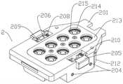
图1是本实施方式中无菌适配器的立体结构示意图。FIG. 1 is a schematic three-dimensional structure diagram of a sterile adapter in this embodiment.
图2是本实施方案中电机盒的结构示意图。FIG. 2 is a schematic structural diagram of a motor box in this embodiment.
图3是本实施方式中电机盒、无菌适配器、器械盒整体的装配示意图。FIG. 3 is a schematic diagram of the overall assembly of the motor box, the sterile adapter, and the instrument box in this embodiment.
图4是本实施方式中突出块处于最外极限位置时动力输出部分的结构示意图。FIG. 4 is a schematic structural diagram of the power output portion when the protruding block is at the outermost limit position in this embodiment.
图5是本实施方式中突出块处于最里极限位置时动力输出部分的结构示意图。FIG. 5 is a schematic structural diagram of the power output part when the protruding block is at the innermost limit position in this embodiment.
图6是本实施方式中无菌适配器横梁与释放开关相关部件的爆炸视图。FIG. 6 is an exploded view of the relevant components of the sterile adapter beam and the release switch in this embodiment.
图7是本实施方式中无菌适配器中间盘、中间盘弹簧、无菌适配器盖的爆炸视图。7 is an exploded view of the sterile adapter intermediate disk, the intermediate disk spring, and the sterile adapter cover in this embodiment.
图8是本实施方式中花键杆的立体结构示意图。FIG. 8 is a schematic three-dimensional structure diagram of the spline rod in this embodiment.
图9是本实施方式中花键套的立体结构示意图。FIG. 9 is a schematic three-dimensional structure diagram of the spline sleeve in this embodiment.
图10是本实施方式中花键套的剖面视图。FIG. 10 is a cross-sectional view of the spline sleeve in this embodiment.
图11是本实施方式中花键套第二端的局部结构示意图。FIG. 11 is a partial structural schematic diagram of the second end of the spline sleeve in this embodiment.
图12是本实施方式中突出块的立体结构示意图。FIG. 12 is a schematic three-dimensional structure diagram of a protruding block in this embodiment.
图13是本实施方式中无菌适配器外壳的立体结构示意图。FIG. 13 is a schematic three-dimensional structural diagram of the sterile adapter housing in this embodiment.
图14是本实施方式中无菌适配器外壳另一视角的立体结构示意图。FIG. 14 is a schematic three-dimensional structural diagram of the sterile adapter housing from another perspective in this embodiment.
图15是本实施方式中无菌适配器外壳开关槽处的局部结构示意图。FIG. 15 is a partial structural schematic diagram of the switch groove of the aseptic adapter housing in this embodiment.
图16是本实施方式中无菌适配器外壳环状凸起与盘孔的局部结构示意图。FIG. 16 is a partial structural schematic diagram of the annular protrusion and the disk hole of the sterile adapter housing in this embodiment.
图17是本实施方式中横梁的立体结构示意图。FIG. 17 is a schematic three-dimensional structure diagram of a beam in this embodiment.
图18是本实施方式中释放开关按钮的立体结构示意图。FIG. 18 is a schematic three-dimensional structural diagram of the release switch button in this embodiment.
图19是本实施方式中释放开关拨卡的立体结构示意图。FIG. 19 is a schematic three-dimensional structural diagram of the release switch dial in this embodiment.
图20是本实施方式中左压轴板的立体结构示意图。FIG. 20 is a schematic three-dimensional structure diagram of the left pressing plate in this embodiment.
图21是本实施方式中右压轴板的立体结构示意图。FIG. 21 is a schematic three-dimensional structure diagram of the right pressing plate in this embodiment.
图22是本实施方式中左横梁挡板的立体结构示意图。FIG. 22 is a schematic three-dimensional structural diagram of the left beam baffle plate in this embodiment.
图23是本实施方式中右横梁挡板的立体结构示意图。FIG. 23 is a schematic three-dimensional structure diagram of the right beam baffle plate in this embodiment.
图24是本实施方式中无菌适配器盖的立体结构示意图。FIG. 24 is a schematic three-dimensional structural diagram of the sterile adapter cover in this embodiment.
图25是本实施方式中无菌适配器盖另一视角的立体结构示意图。FIG. 25 is a schematic three-dimensional structural diagram of the sterile adapter cover in the present embodiment from another perspective.
图26是本实施方式中中间盘的立体结构示意图。FIG. 26 is a schematic three-dimensional structure diagram of the intermediate disk in this embodiment.
图27是本实施方式中中间盘另一视角的立体结构示意图。FIG. 27 is a schematic three-dimensional structural diagram of the intermediate disk in the present embodiment from another viewing angle.
图28是本实施方式中器械盒的立体结构示意图。FIG. 28 is a schematic three-dimensional structure diagram of the instrument case in this embodiment.
图29是本实施方式中从动盘的立体结构示意图。FIG. 29 is a schematic three-dimensional structure diagram of the driven disk in this embodiment.
附图标记说明如下:The reference numerals are explained as follows:
1~电机盒;2~无菌适配器;3~器械盒;101~电机壳;102~电机组;103~花键杆;104~花键套;105~压紧力弹簧;106~突出块;107~弹出弹簧;201~无菌适配器外壳;202~横梁;203~横梁弹簧;204~紧定螺钉;205~释放开关按钮;206~释放开关拨卡;207~释放开关拨卡轴;208~左压轴板;209~右压轴板;210~释放开关弹簧;211~左横梁挡板;212~右横梁挡板;213~无菌适配器盖;214~中间盘;215~中间盘弹簧;301~器械盒上盖;302~从动盘;10301~减速器轴孔;10302~外花键;10303~花键杆圆台;10401~内花键;10402~平面凹槽;10403~花键套螺纹孔;10404~花键套圆台;10405~突出块凹槽;10406~凹陷特征;10407~弹簧沉孔;10601~突出块斜面;10602~弧形表面;10603~凸起特征;10604~弹出弹簧圆台;10605~薄壁;20101~外突特征;20102~内陷特征;20103~恻耳;20104~横梁槽;20105~横梁槽弹簧孔;20106~挡板座;20107~挡板螺纹孔;20108~开关槽;20109~圆台;20110~轴底座;20111~底座圆台;20112~底座螺纹孔;20113~圆柱槽;20114~盖槽;20115~圆柱台;20116~圆柱台螺纹孔;20117~盘孔;20118~环状凸起;20119~旋转抑制凹陷;20120~前条形凸起;20121~后条形凸起;20201~宽梁部;20202~凸梁部;20203~拨卡槽;20501~按钮主体;20502~按钮挡板;20503~按钮圆台;20504~安装槽;20601~拨卡头;20602~拨卡轴孔;20603~拨卡凸爪;20801~(左压轴板)小圆孔;20802~(左压轴板)大圆孔;20803~(左压轴板)半轴孔;20804~(左压轴板)螺钉切台;20901~(右压轴板)小圆孔;20902~(右压轴板)大圆孔;20903~(右压轴板)半轴孔;20904~(右压轴板)螺钉切台;21101~(左横梁挡板)挡板透孔;21102~(左横梁挡板)横切槽;21201~(右横梁挡板)挡板透孔;21202~(右横梁挡板)横切槽;21301~圆孔;21302~沉孔;21303~圆台;21401~中心圆孔;21402~径向凹陷;21403~平行凸爪;21404~锥形凸爪;21405~环形凸台;21406~旋转抑制凸起;30101~器械盒上盖凹陷特征;30102~前条形凹陷;30201~从动接口。1~motor box; 2~sterile adapter; 3~instrument box; 101~motor case; 102~motor unit; 103~spline rod; 104~spline sleeve; 105~compression force spring; 106~protruding block ;107~pop-up spring;201~sterile adapter housing;202~beam; 203~beam spring; 204~set screw; 205~release switch button; 206~release switch dial; 207~release switch dial shaft; 208 ~Left pressure plate; 209~Right pressure plate; 210~Release switch spring; 211~Left beam stop; 212~Right beam stop; 213~Aseptic adapter cover; 214~Intermediate disc; 215~Intermediate disc spring; 301 ~Instrument box upper cover; 302~Driver plate; 10301~Reducer shaft hole; 10302~External spline; 10303~Spline rod round table; 10401~Internal spline; 10402~Flat groove; Hole; 10404~spline sleeve round table; 10405~protruding block groove; 10406~recessed feature; 10407~spring counterbore; 10601~protruding block bevel; 10602~curved surface; 10603~raised feature; ;10605~thin wall;20101~outward protrusion feature; 20102~indentation feature; 20103~here; 20104~beam groove; 20105~beam groove spring hole; 20106~bezel seat; 20107~bezel thread hole; Switch groove; 20109~round table; 20110~axis base; 20111~base round table; 20112~base threaded hole; 20113~cylindrical groove; 20114~cover groove; 20118~annular protrusion; 20119~rotation inhibition depression; 20120~front bar-shaped protrusion; 20121~rear bar-shaped protrusion; 20201~wide beam section; 20202~convex beam section; 20203~dial card slot; 20501~button body ;20502~Button bezel; 20503~Button round table; 20504~Installation slot; 20601~Pick head; 20602~Pick shaft hole; 20603~Pick up claw; (Left pressure plate) large round hole; 20803~ (left pressure plate) half shaft hole; 20804~ (left pressure plate) screw cutting table; 20901~ (right pressure plate) small round hole; 20902~ (right pressure plate) large round hole ;20903~(right pressure plate) half shaft hole; 20904~(right pressure plate) screw cutting table; 21101~(left beam baffle) baffle through hole; 21102~ (left beam baffle) cross cutting groove; 21201~ (right beam baffle) baffle through hole; 21202~(right beam baffle) cross-cutting groove; 21301~round hole; 21302~counter hole; 21303~round table; 21401~center round hole; 03~parallel claws; 21404~tapered claws; 21405~annular bosses; 21406~rotation inhibiting protrusions; 30101~the concave features of the upper cover of the instrument box; 30102~the front strip-shaped concavities;
具体实施方案specific implementation
如图1至图29所示,本实施方案提供了一种用于单孔微创手术机器人的无菌适配器与动力输出部分。As shown in FIGS. 1 to 29 , this embodiment provides a sterile adapter and power output part for a single-hole minimally invasive surgical robot.
作为本实施方式的各种改进详述如下。Various modifications of the present embodiment are described in detail below.
如图3所示,As shown in Figure 3,
所述无菌适配器2安置于电机盒1上,所述器械盒3安装于无菌适配器2上,电机扭矩经无菌适配器、器械盒传递到末端的手术器械。The
如图2所示,as shown in
所述电机盒1包括:电机壳101、电机组102与动力输出部分;电机组能够在电机壳内沿纵向移动。The motor box 1 includes: a
如图4、图5所示,As shown in Figure 4 and Figure 5,
一种用于单孔微创手术机器人的无菌适配器以及动力传输部分。所述动力输出部分组件包括:A sterile adapter and power transmission part for a single-hole minimally invasive surgical robot. The PTO assembly includes:
花键杆103,所述花键杆连接于电机减速器输出轴;
花键套104,所述花键套一端与所述花键杆连接,一端与中间盘连接;
压紧力弹簧105,所述压紧力弹簧安置于花键套内;A
至少一个突出块106,所述突出块安置于花键套一端径向方向;at least one protruding
至少一个弹出弹簧107,所述弹出弹簧安置于花键套内,与突出块连接;at least one
如图1、图6、图7所示,As shown in Figure 1, Figure 6, and Figure 7,
所述无菌适配器2,其组件包括:The
无菌适配器外壳201,所诉无菌适配器外壳201安置在电机盒1与器械盒3之间;The
横梁202,所述横梁安置于无菌适配器壳外壳两侧,用于连接器械盒;
横梁弹簧203,所述横梁弹簧安置于所述横梁外科,与无菌适配器外壳连接;
紧定螺钉204,所述紧定螺钉安置于无菌适配器外壳两侧;Set
释放开关按钮205,所述释放开关按钮安置所述无菌适配器外科两侧;
释放开关拨卡206,所述释放开关拨卡连接所述释放开关按钮与所述横梁;A
释放开关拨卡轴207,所述释放开关拨卡轴将所述释放开关拨卡安置于所述无菌适配器外科上;the release
释放开关压轴板,所述释放开关压轴板分为左压轴板208与右压轴板209,安置于所述拨卡轴上侧;The release switch pressing plate, which is divided into a left
释放开关弹簧210,所述释放开关弹簧连接释放开关按钮与无菌适配器外科;
横梁挡板,所述横梁挡板分为左横梁挡板211与右横梁挡板212,安置于所述无菌适配器外科两侧;The beam baffle, the beam baffle is divided into a
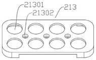
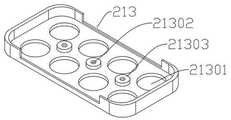
无菌适配器盖213,所述无菌适配器盖安置于所述无菌适配器壳上端;A
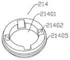
至少一个中间盘214,所述中间盘安置于所述无菌适配器壳与无菌适配器盖中间并被构造成将扭矩从驱动器传递到器械盒;at least one
至少一个中间盘弹簧215,所述中间盘弹簧安置于所述中间盘上并与无菌适配器盖接触。At least one
所述动力输出部分连接减速器轴,能够与电机组一同在电机壳内部沿纵向轴线移动。The power output part is connected to the reducer shaft and can move along the longitudinal axis together with the motor group inside the motor housing.
所示电机组可能在电机壳内部沿纵向移动;The motor unit shown may move longitudinally inside the motor housing;
所述动力输出部分可以处于至少两种位置。在非工作状态,所述电机组102与动力输出部分位于所述电机壳101上部,所述花键套104下端与所述无菌适配器2分离,称为非接合位置。在工作状态,所述电机组102与动力输出部分位于所述电机壳101下部,所述花键套104下端与无菌适配器2接触,称为接合位置;The power take-off portion may be in at least two positions. In the non-working state, the
当所述无菌适配器2安装至电机盒1上时,所述电机盒1上的微动开关被压下,所述电机组102与所述动力输出部分开始沿纵向下移,所述电机组102与所述动力输出部分由所述非接合位置移动到所述接合位置;到达所述接合位置时,所述电机盒1上的光电传感器检测到所述电机组101,所述电机组101与所述动力输出部分停止下移;When the
所述电机组101与所述动力输出部分位于接合位置时,所述压紧力弹簧105被压缩,压紧力通过花键套104作用于中间盘214上;When the
所述光电传感器检测到所述电机组102与所述动力输出部分处于所述接合位置时,所述电机组上电机开始旋转,带动所述花键杆103与所述花键套104旋转,所述花键套104与所述中间盘214开始配合。When the photoelectric sensor detects that the
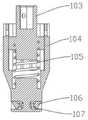
如图8所示,As shown in Figure 8,
所述花键杆103沿轴线方向分为第一端与第二端,所述第一端有减速器轴孔10301,与减速器轴连接;所述第二端为外花键10302与花键杆圆台10303,所述外花键与所述花键套连接,所述花键杆圆台用于固定所述压紧力弹簧105。The
如图9、图10、图11所示,As shown in Figure 9, Figure 10, and Figure 11,
所述花键套104沿轴线方向分为第一端与第二端,所述第一端有内花键10401,与所述花键杆第二端外花键连接,扭矩通过所述花键杆传递给所述花键套,所述内花键底面有花键套圆台10404,所述花键套圆台用于固定所述压紧力弹簧;所述第一端还有平面凹槽10402与螺纹孔10403,所述螺纹孔连接螺钉,来实现花键杆103的轴向限位,使其不能脱离花键套;所述第二端与所述中间盘214连接,能够将扭矩传递给所述中间盘;The
所述花键套第二端沿径向至少分布有一个突出块凹槽10405,供所述突出块106插入连接。The second end of the spline sleeve is radially distributed with at least one protruding
所述花键杆103能在所述花键套104内沿轴向移动,所述电机组102由非接合位置移动到接合位置过程中,所述压紧力弹簧105压缩,所述花键杆相对于所述花键套下移;The
所述突出快凹槽10405上下表面面相互平行,左右侧面相互平行;The upper and lower surfaces of the protruding
所述突出快凹槽10405左右侧面有供所述突出块配合的凹陷特征10406;The left and right sides of the protruding
所述突出快凹槽10405底面有用于固定所述弹出弹簧的弹簧沉孔10407。The bottom surface of the protruding
如图12所示,As shown in Figure 12,
所述突出块106起到将扭矩由花键套104传递给中间盘214的作用;The protruding
所述突出块106上下表面相互平行,靠近所述花键套104轴线一端的左右侧面相互平行,远离所述花键套轴线一端的左右侧面为有一定夹角的两个斜面10601,两斜面沿远离所述花键套轴线方向靠拢,以便于与所述中间盘214上对应特征配合;The upper and lower surfaces of the
所述突出块具有弧形表面10602,所述弧形表面与所述中间盘配合;the protruding block has an
所述突出块106靠近所述花键套104轴线一端左右侧面分布有与所述花键套凹陷特征10406配合的凸起特征10603;Protruding features 10603 that cooperate with the
所述凸起特征10603在所述突出块106沿所述突出块凹槽10405径向移动时起到限位作用;The
所述突出块106具有固定弹出弹簧的突出快圆台10604;The protruding
如图4、图5所示,As shown in Figure 4 and Figure 5,
所述突出块106沿径向移动到所述突出块凹槽10405最里面时,所述突出块处于最里极限位置;When the
所述突出块106沿径向移动到所述凸起特征10603与所述突出快凹槽内的所述凹陷特征10406最外沿接触时,称为所述突出块的最外极限位置;When the
所述突出块位于所述最外极限位置时,所述突出块远离所述花键套轴线的一端暴露在所述突出快凹槽10405外面;When the protruding block is located at the outermost limit position, one end of the protruding block away from the axis of the spline sleeve is exposed outside the protruding
所述突出块材料具有一定韧性,靠近所述花键套轴线一端为薄壁10605,使得其可以发生微小变形,易于安置于所述花键套上的所述突出快凹槽10405内;The protruding block material has a certain toughness, and one end near the axis of the spline sleeve is a
所述的弹出弹簧(107)安置于所述花键套第二端的所述突出快凹槽10405内,与所述突出块上的弹出弹簧圆台10604连接;The ejection spring (107) is arranged in the protruding
在所述突出块弧形表面10602受到沿所述花键套轴线方向的压力时,所述弹出弹簧107收缩,所述突出块106整体缩入所述花键套第二端的所述突出快凹槽10405内。When the arc-shaped
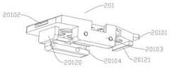
如图13、图14、图15、图16所示,As shown in Figure 13, Figure 14, Figure 15, Figure 16,
所述无菌适配器外壳安置于所述电机盒上;the sterile adapter housing is arranged on the motor box;
所述无菌适配器外壳包括:外突特征20101,所述外突特征被构造成插入所述电机盒上凹陷处;内陷特征20102,所述内陷特征被构造成能接纳所述电机盒上的特征部。The sterile adapter housing includes: an overhanging
所述无菌适配器外壳两侧有侧耳20103,所述侧耳用于安置横梁202以及释放开关的相关部件;There are
所述侧耳20103内侧开有横梁槽20104,所述横梁槽被构造成沿长度方向一端封闭,一端开口,槽长与所述横梁长度相等,槽口略小,起到防止横梁沿宽度方向移出的作用;A
所述横梁202沿长度方向插入所述横梁槽20104中,安装完成后,末端依靠所述横梁挡板211来限制所述横梁沿长度方向滑出,所述横梁202被允许在所述横梁槽20104内沿宽度方向在一定范围内移动;The
所述横梁槽20104内侧面有安置所述横梁弹簧203的横梁弹簧孔20105,所述横梁弹簧孔20105延伸到所述侧耳外表面,且靠近外表面一端孔面有螺纹线,用于安置所述紧定螺钉204。On the inner side of the
所述横梁弹簧203由所述横梁弹簧孔20105放入,一端接触所述横梁202,另一端接触所述紧定螺钉204;The
安装器械盒3时,所述器械盒由所述无菌适配器外壳201下端插入,所述横梁202在所述器械盒上沿作用下向所述横梁槽20104内侧移动,所述横梁弹簧203被压缩;所述器械盒3安装到位后,所述横梁202在横梁弹簧203的作用下向所述横梁槽20104外侧移动,所述横梁203与所述器械盒上盖301左右侧面用于接收横梁的凹陷特征30101配合,器械盒(3)安装完成;When installing the
所述侧耳20103前端(所述横梁槽开口处)有安置所述横梁挡板211的挡板座20106,所述挡板座被构造为配合所述横梁挡板的外形特征,所述挡板座上方有挡板螺纹孔20107;The front end of the side ear 20103 (at the opening of the beam groove) has a
所述侧耳20103上端有安置释放开关相关部件的开关槽20108,所述开关槽为T型结构,两侧突出的挡板能够防止所述释放开关按钮205脱离所述开关槽20108;The upper end of the
所述开关槽20108内侧面有用于固定释放开关弹簧210的圆台20109;The inner side of the
所述开关槽底面有安置释放开关拨卡轴的轴底座20110,所述轴底座有配合释放开关拨卡轴207的圆柱槽20113,所述轴底座有底座圆台20111与底座螺纹孔20112,所述底座圆台20111与底座螺纹孔20112用于连接与固定释放开关压轴板;The bottom surface of the switch groove is provided with a
所述开关槽底面、左右轴底座中间被打通,使得所述开关槽20108与所述横梁槽20104连接,所述释放开关拨卡206能伸入所述横梁槽20104;The bottom surface of the switch slot and the middle of the left and right shaft bases are opened, so that the
所述中间盘214安置于所述无菌适配器壳201与所述无菌适配器盖213之间,并能在纵向短距离内运动。The
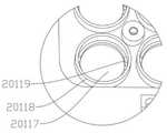
所述无菌适配器壳201上有安置无菌适配器盖213的盖槽20114,所述盖槽底面有固定安置所述中间盘的盘孔20117与环状凸起20118,所述盘孔与环状凸起只能限制中间盘214在水平面内的移动,允许中间盘在纵向的移动。所述盘孔与所述环状凸起同轴;The
所述无菌适配器壳201与无菌适配器盖213由螺钉固定连接。所述无菌适配器壳有至少一个圆柱台20115,所述圆柱台上有圆柱台螺纹孔20116;The
所述无菌适配器外壳底面有用于抑制中间盘旋转的旋转抑制凹陷20119,所述旋转抑制凹陷位于所述环状凸起20118内侧、盘孔20117边缘,与所述中间盘214上的旋转抑制凸起21406配合;所述旋转抑制凹陷在花键套与中间盘配合时,起到抑制中间盘旋转的作用;The bottom surface of the sterile adapter shell is provided with a
所述无菌适配器下端面设置有前条形凸起20121与后条形凸起20120,所述前条形凸起、所述后条形凸起分别与所述器械盒上盖301上对应的前条形凹陷30102、后侧面配合,用于限制器械盒3在水平方向的移动。The lower end surface of the sterile adapter is provided with a front bar-shaped
如图17所示,As shown in Figure 17,
用于所示无菌适配器2与器械盒3连接的零件有:横梁202、释放开关按钮205、释放开关拨卡206、压轴板、横梁挡板;The parts used for connecting the shown
所述横梁(202)装配于所述无菌适配器侧耳20103内侧的所述横梁槽20104内,用于安装承载所述器械盒;The beam (202) is assembled in the
所述横梁有宽梁部20201,所述宽梁部高度大于所述横梁槽20104的槽口高度,使得横梁不会从槽口脱出横梁槽;The beam has a
所述横梁有凸梁部20202,所述凸梁部与所述器械盒上盖301的对应凹陷特征30101配合,使得所述器械盒3稳固的安装在所述无菌适配器2上;The beam has a
所述横梁有拨卡槽20203,所述释放开关拨卡206的下端抵在所述拨卡槽内,所述释放开关拨卡绕所述释放开关拨卡轴207旋转,带动横梁202向横梁槽20104内侧移动;The beam has a
释放开关按钮205包括:按钮主体20501、按钮挡板20502、按钮圆台20503、安装槽20504;所述按钮挡板分布于所述按钮主体两侧,与所述无菌适配器开关槽20108的两侧突出接触,防止所述释放开关按钮脱离开关槽;所述按钮圆台用于固定释放开关弹簧210;所述释放开关按钮主体内侧切有两个安装槽,所述安装槽是为了便于所述释放开关按钮的安装;The
如图19所示,As shown in Figure 19,
所述释放开关拨卡206包括:拨卡头20601、拨卡轴孔20602、拨卡凸爪20603;所述拨卡头抵在所述释放开关按钮的按钮主体内侧,所述拨卡通过安置在拨卡轴孔内的所述释放开关拨卡轴安置在开关槽内,拨卡凸爪抵在所述横梁的所述拨卡槽内;The release
当按下所述释放开关按钮205时,所述释放开关弹簧210压缩,所述拨卡头随释放开关按钮移动,所述释放开关拨卡206绕所述释放开关拨卡轴207转动,所述拨卡凸爪向着所述释放开关按钮相反的运动方向移动,带着横梁202向横梁槽20104内侧移动,所述横梁弹簧203压缩,所述横梁缩入横梁槽内,所述器械盒3从所述无菌适配器2上拆下;松开所述释放开关按钮,在释放开关弹簧的作用下,所述释放开关按钮回到原位,所述横梁在横梁弹簧作用下向所述横梁槽外侧移动;When the
如图20、图21所示,As shown in Figure 20 and Figure 21,
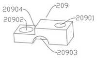
所述压轴板分为:左压轴板208与右压轴板209,所述左压轴板安置于所述轴底座的一侧上,包括:小圆孔20801、大圆孔20802、半轴孔20803、螺钉切台20804,所述小圆孔与所述轴底座20110上的所述底座圆台20111配合;所述大圆孔与所述轴底座上的底座螺纹孔20112同轴,用于插入螺钉;所述半轴孔与所述释放开关拨卡轴207半径相等;The pressing plate is divided into a left
所述右压轴板209与所述左压轴板208完全镜像对称,通过螺钉安装于所述轴底座20110上,所述底座圆台于所述小圆孔配合,用于压轴板的固定,所述左、右压轴板通过半轴孔将所述释放开关拨卡轴207固定于所述轴底座20110上,所述螺钉切台20804使得螺钉头不超过所述压轴板上表面。The right
如图22、图23所示,As shown in Figure 22 and Figure 23,
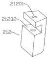
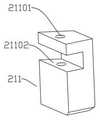
所述横梁挡板分为:左横梁挡板211与右横梁挡板212,所述左横梁挡板安置于所述无菌适配器外壳201左侧的挡板座20106上,所述左横梁挡板上的横切槽21102与所述挡板座的外凸特征配合;所述横梁挡板上的挡板透孔21101与所述挡板座上方的螺纹孔20107同轴;The beam baffle is divided into: a
所述右横梁挡板212与所述左横梁挡板完全镜像对称,安置于所述无菌适配器外壳右侧,所述横梁挡板通过螺钉固定于所述挡板座上,将所述横梁槽20104的开口一端封闭,使得所述横梁无法脱离所述横梁槽。The
如图24、如25所示,As shown in Figure 24 and 25,
所述无菌适配器盖213外侧面与所述无菌适配器外壳上的盖槽20114配合;The outer side of the
安装完成后,所述无菌适配器盖上表面与所述无菌适配器壳上表面处于同一水平面上;After the installation is completed, the upper surface of the sterile adapter cover and the upper surface of the sterile adapter shell are on the same level;
安装完成后,所述无菌适配器壳201与所述无菌适配器盖213中间有足够的纵向空间,以供中间盘214沿纵向移动;After the installation is completed, there is sufficient longitudinal space between the
所述无菌适配器盖213用于限制所述中间盘214纵向移动的范围;The
所述无菌适配器盖213也用于限制所述中间盘弹簧215的一端,使其能够压缩;The
所述无菌适配器盖213上表面有供所述花键套插入的圆孔21301;The upper surface of the
所述圆孔21301半径大于所述花键套104第二端的半径,小于所述中间盘弹簧215中经,小于所述中间盘环形凸台21405半径;The radius of the
所述无菌适配器盖213安装完成后,所述无菌适配器盖上的圆孔与所述花键套、所述无菌适配器壳上的圆孔同轴;After the
所述无菌适配器盖上表面有至少一个沉孔21302;There is at least one
所述无菌适配器盖内侧有安置所述沉孔的圆台21303;There is a round table 21303 on the inner side of the sterile adapter cover to place the counterbore;
所述沉孔21303与所述无菌适配器壳上的螺纹孔20116同轴。The
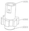
如图26、图27所示,As shown in Figure 26 and Figure 27,
所述中间盘214包括:The
从动接口,所述从动接口被设计为与所述花键套第二端配合;A driven interface, the driven interface is designed to cooperate with the second end of the splined sleeve;
驱动接口,所述驱动接口与从动盘配合;a drive interface, the drive interface cooperates with the driven disc;
环形凸台21405,所述环形凸台安置于于所述中间盘侧面中部;An
旋转抑制凸起21406,所述旋转抑制凸起与所述无菌适配器壳上的凹陷特征配合;a rotation inhibiting protrusion 21406 that mates with a recessed feature on the sterile adapter shell;
所述中间盘214安置于无菌适配器壳上的圆孔20117与环状凸起20118中;The
所述从动接口包括中心圆孔21401与至少一个径向凹陷21402,所述中心圆孔与所述花键套第二端配合,所述径向凹陷与所述突出块配合;The driven interface includes a central circular hole 21401 and at least one
当所述动力输出部分由非接合位置移动到接合位置时,若所述突出块与所述径向凹陷未完全匹配,所述突出块在所述中心圆孔上沿作用下移动到最里极限位置,即完全缩入所述花键套第二端的所述突出块凹槽内部;When the power output part moves from the non-engaging position to the engaging position, if the protruding block does not completely match the radial recess, the protruding block moves to the innermost limit under the action of the upper edge of the central circular hole position, that is, fully retracted into the groove of the protruding block at the second end of the spline sleeve;
所述环形凸台21405半径大于所述中间盘214两端半径;The radius of the
所述环形凸台21405上表面与所述中间盘弹簧215下端接触,下表面与所述无菌适配器壳201接合。The upper surface of the
当传感器检测到所述动力输出部分完全移动到接合位置时,电机带动所述动力输出部分旋转,所述中间盘在旋转抑制凸起的作用下保持不动,所述动力输出部分旋转至所述突出块与所述中间盘从动接口的径向凹陷对齐时,在所述弹出弹簧的作用下,所述突出块远离轴线一端弹出所述花键套凹槽,突出块位于最外极限位置,使得所述突出块能与所述径向凹陷匹配。When the sensor detects that the power output part is completely moved to the engaging position, the motor drives the power output part to rotate, the intermediate disc remains stationary under the action of the rotation restraining protrusion, and the power output part rotates to the When the protruding block is aligned with the radial recess of the intermediate disk driven interface, under the action of the ejection spring, the end of the protruding block away from the axis is ejected from the spline sleeve groove, and the protruding block is located at the outermost limit position, The protruding blocks can be matched with the radial recesses.
如图26、图27、图29所示,As shown in Figure 26, Figure 27, and Figure 29,
所述驱动接口被设计为在下压力的作用下可以自动旋转耦合与从动盘接口的形式;The drive interface is designed to be coupled with the driven disc interface automatically under the action of downward pressure;
提出一种所述驱动接口的结构形式:A structural form of the drive interface is proposed:
所述驱动接口包括平行凸爪21403与锥形凸爪21404,所述平行凸爪位于所述锥形凸爪上端;The drive interface includes a parallel
所述平行凸爪侧面垂直于中间盘下端面,其作用为:器械盒3安装完成时,将中间盘214沿纵向提升一段与平行凸爪等高的距离,使得旋转抑制凸起21406脱离无菌适配器壳上旋转抑制凹陷20119;The side surface of the parallel raised claws is perpendicular to the lower end face of the middle plate, and its function is: when the installation of the
所述锥形凸爪与所述从动盘302上的从动盘接口30201配合,所述锥形凸爪侧面包括:外凸的弧面与内陷部分;The conical convex claw is matched with the driven
外凸的弧面上任意一点的弧度大于以同一水平面上中间盘轴线上的点为圆心,向任意一点所做圆的弧度;The radian of any point on the convex arc surface is greater than the radian of the circle drawn to any point with the point on the axis of the intermediate disk on the same horizontal plane as the center of the circle;
内陷部分具有一定圆角;The concave part has a certain rounded corner;
若所述锥形凸爪21404在预紧力作用下,未与所述从动盘接口30201完全配合,所述中间盘能在所述无菌适配器壳201与所述无菌适配器盖213之间沿纵向上移一段距离;If the conical lug 21404 is not fully engaged with the driven
电机启动后,未与所述从动盘接口30201完全配合的所述中间盘214可以通过旋转来实现完全配合。After the motor is started, the
所述旋转抑制凸起21406安置于所述环形凸台21405下表面;The rotation inhibiting protrusion 21406 is arranged on the lower surface of the
所述旋转抑制凸起包括两个斜面与一个平行于所述中间盘214下表面的平面;The rotation restraining protrusion includes two inclined surfaces and a plane parallel to the lower surface of the
所述旋转抑制凸起与所述无菌适配器壳上相应旋转抑制凹陷20119配合;The rotation inhibiting protrusions are matched with the corresponding
所述旋转抑制凸起的斜面的斜度要求为,在减速器轴输出力矩的作用下,旋转抑制凸起21406可沿斜面脱离旋转抑制凹陷20119;The slope of the inclined surface of the rotation restraining protrusion is required to be, under the action of the output torque of the reducer shaft, the rotation restraining protrusion 21406 can be separated from the
所述突出块106未与所述径向凹陷21402配合完成时,电机带动所述花键套104旋转,所述中间盘214在所述旋转抑制凸起21406作用下,与无菌适配器外壳201保持相对静止;When the
所述突出块106与所述径向凹陷21402配合完成后,所述旋转抑制凸起21406在电机扭矩作用下沿斜面脱离旋转抑制凹陷20119。After the
Claims (10)
Translated fromChinesePriority Applications (1)
| Application Number | Priority Date | Filing Date | Title |
|---|---|---|---|
| CN202111067837.4ACN114533268A (en) | 2021-09-13 | 2021-09-13 | Sterile adapter and power output part |
Applications Claiming Priority (1)
| Application Number | Priority Date | Filing Date | Title |
|---|---|---|---|
| CN202111067837.4ACN114533268A (en) | 2021-09-13 | 2021-09-13 | Sterile adapter and power output part |
Publications (1)
| Publication Number | Publication Date |
|---|---|
| CN114533268Atrue CN114533268A (en) | 2022-05-27 |
Family
ID=81668702
Family Applications (1)
| Application Number | Title | Priority Date | Filing Date |
|---|---|---|---|
| CN202111067837.4APendingCN114533268A (en) | 2021-09-13 | 2021-09-13 | Sterile adapter and power output part |
Country Status (1)
| Country | Link |
|---|---|
| CN (1) | CN114533268A (en) |
Cited By (1)
| Publication number | Priority date | Publication date | Assignee | Title |
|---|---|---|---|---|
| WO2024109626A1 (en)* | 2022-11-25 | 2024-05-30 | 深圳康诺思腾科技有限公司 | Sterile adapter |
Citations (9)
| Publication number | Priority date | Publication date | Assignee | Title |
|---|---|---|---|---|
| CN101292902A (en)* | 2008-06-13 | 2008-10-29 | 哈尔滨工程大学 | Manual micromanipulators for minimally invasive surgery |
| CN102058436A (en)* | 2011-01-10 | 2011-05-18 | 天津大学 | Locking device for surgical robot quick replacement mechanism |
| CN102630154A (en)* | 2009-09-23 | 2012-08-08 | 伊顿株式会社 | Sterile adapter, connection structure of rotating wheel and connection structure of surgical instruments |
| CN104042278A (en)* | 2013-03-14 | 2014-09-17 | 伊西康内外科公司 | Drive system lockout arrangements for modular surgical instruments |
| BR112014032776A2 (en)* | 2012-06-28 | 2017-06-27 | Ethicon Endo Surgery Inc | surgical instrument system including replaceable end actuators |
| CN108784838A (en)* | 2013-08-15 | 2018-11-13 | 直观外科手术操作公司 | Instrument sterile adaptor driving interface |
| CN109602495A (en)* | 2013-08-15 | 2019-04-12 | 直观外科手术操作公司 | Instrument sterile adaptor drives feature |
| CN110996806A (en)* | 2017-08-03 | 2020-04-10 | 爱惜康有限责任公司 | Emergency auxiliary device of surgical operation system |
| CN113349938A (en)* | 2021-07-14 | 2021-09-07 | 深圳康诺思腾科技有限公司 | Surgical robot |
- 2021
- 2021-09-13CNCN202111067837.4Apatent/CN114533268A/enactivePending
Patent Citations (11)
| Publication number | Priority date | Publication date | Assignee | Title |
|---|---|---|---|---|
| CN101292902A (en)* | 2008-06-13 | 2008-10-29 | 哈尔滨工程大学 | Manual micromanipulators for minimally invasive surgery |
| CN102630154A (en)* | 2009-09-23 | 2012-08-08 | 伊顿株式会社 | Sterile adapter, connection structure of rotating wheel and connection structure of surgical instruments |
| CN104706426A (en)* | 2009-09-23 | 2015-06-17 | 伊顿株式会社 | Sterile adapter, connection structure of wheel and connection structure of surgical instrument |
| CN107028660A (en)* | 2009-09-23 | 2017-08-11 | 伊顿株式会社 | The draw bail of sterile adapter, runner draw bail and surgery instrument |
| CN102058436A (en)* | 2011-01-10 | 2011-05-18 | 天津大学 | Locking device for surgical robot quick replacement mechanism |
| BR112014032776A2 (en)* | 2012-06-28 | 2017-06-27 | Ethicon Endo Surgery Inc | surgical instrument system including replaceable end actuators |
| CN104042278A (en)* | 2013-03-14 | 2014-09-17 | 伊西康内外科公司 | Drive system lockout arrangements for modular surgical instruments |
| CN108784838A (en)* | 2013-08-15 | 2018-11-13 | 直观外科手术操作公司 | Instrument sterile adaptor driving interface |
| CN109602495A (en)* | 2013-08-15 | 2019-04-12 | 直观外科手术操作公司 | Instrument sterile adaptor drives feature |
| CN110996806A (en)* | 2017-08-03 | 2020-04-10 | 爱惜康有限责任公司 | Emergency auxiliary device of surgical operation system |
| CN113349938A (en)* | 2021-07-14 | 2021-09-07 | 深圳康诺思腾科技有限公司 | Surgical robot |
Non-Patent Citations (1)
| Title |
|---|
| 吕雪青;潘冬青;: "机器人系统手术的巡回配合", 护理实践与研究, no. 21* |
Cited By (1)
| Publication number | Priority date | Publication date | Assignee | Title |
|---|---|---|---|---|
| WO2024109626A1 (en)* | 2022-11-25 | 2024-05-30 | 深圳康诺思腾科技有限公司 | Sterile adapter |
Similar Documents
| Publication | Publication Date | Title |
|---|---|---|
| US12156652B2 (en) | Adapter assembly for interconnecting electromechanical surgical devices and surgical loading units, and surgical systems thereof | |
| EP4085864B1 (en) | Transmission assembly, drive box, surgical instrument system, and robot system | |
| CN101264605B (en) | Robot arm coupling device | |
| US10806466B2 (en) | High speed drill configured with multiple cutting burr attachments | |
| EP2204265B1 (en) | Universal joint | |
| CN110384556B (en) | Quick change mechanism, instrument clamping hand adopting same and surgical operation robot | |
| CN107595394B (en) | Surgical instrument quick-change mechanism | |
| CN114533268A (en) | Sterile adapter and power output part | |
| CN109262662B (en) | Coupling unit | |
| CN118319496A (en) | A surgical instrument quick-change device and a quick-change method | |
| WO2024148331A3 (en) | Surgical tool holder for intraocular robotic surgical systems | |
| WO2023124946A1 (en) | Guide wire or catheter controller and surgical robot | |
| EP2006565A1 (en) | Gear apparatus | |
| CN110384557B (en) | Combined positioning mechanism, instrument clamping hand adopting same and surgical operation robot | |
| CN212304084U (en) | Connection structure and cable pulling device | |
| CN216078038U (en) | Clutch device | |
| CN116849833B (en) | Connecting device of medical instrument | |
| CN113446327B (en) | Clutch | |
| CN112022278A (en) | Skull drill bit capable of adjusting thickness of bone pad | |
| CN213906485U (en) | Motor quick-change structure directly connected and installed | |
| CN204562262U (en) | Medical stapler | |
| KR102635808B1 (en) | Module detachable structure for medical equipment | |
| CN112542917A (en) | Motor quick-change structure directly connected and installed | |
| CN111271509A (en) | Locking valve | |
| CN221120699U (en) | Power connection structure for vascular intervention surgical robot and surgical robot |
Legal Events
| Date | Code | Title | Description |
|---|---|---|---|
| PB01 | Publication | ||
| PB01 | Publication | ||
| SE01 | Entry into force of request for substantive examination | ||
| SE01 | Entry into force of request for substantive examination | ||
| WD01 | Invention patent application deemed withdrawn after publication | ||
| WD01 | Invention patent application deemed withdrawn after publication | Application publication date:20220527 |