CN114533198A - Shock wave balloon catheter device and medical equipment - Google Patents
Shock wave balloon catheter device and medical equipmentDownload PDFInfo
- Publication number
- CN114533198A CN114533198ACN202210172787.4ACN202210172787ACN114533198ACN 114533198 ACN114533198 ACN 114533198ACN 202210172787 ACN202210172787 ACN 202210172787ACN 114533198 ACN114533198 ACN 114533198A
- Authority
- CN
- China
- Prior art keywords
- shock wave
- balloon
- electrode
- catheter device
- balloon catheter
- Prior art date
- Legal status (The legal status is an assumption and is not a legal conclusion. Google has not performed a legal analysis and makes no representation as to the accuracy of the status listed.)
- Pending
Links
Images


Classifications
- A—HUMAN NECESSITIES
- A61—MEDICAL OR VETERINARY SCIENCE; HYGIENE
- A61B—DIAGNOSIS; SURGERY; IDENTIFICATION
- A61B17/00—Surgical instruments, devices or methods
- A61B17/22—Implements for squeezing-off ulcers or the like on inner organs of the body; Implements for scraping-out cavities of body organs, e.g. bones; for invasive removal or destruction of calculus using mechanical vibrations; for removing obstructions in blood vessels, not otherwise provided for
- A61B17/22004—Implements for squeezing-off ulcers or the like on inner organs of the body; Implements for scraping-out cavities of body organs, e.g. bones; for invasive removal or destruction of calculus using mechanical vibrations; for removing obstructions in blood vessels, not otherwise provided for using mechanical vibrations, e.g. ultrasonic shock waves
- A61B17/22012—Implements for squeezing-off ulcers or the like on inner organs of the body; Implements for scraping-out cavities of body organs, e.g. bones; for invasive removal or destruction of calculus using mechanical vibrations; for removing obstructions in blood vessels, not otherwise provided for using mechanical vibrations, e.g. ultrasonic shock waves in direct contact with, or very close to, the obstruction or concrement
- A61B2017/22025—Implements for squeezing-off ulcers or the like on inner organs of the body; Implements for scraping-out cavities of body organs, e.g. bones; for invasive removal or destruction of calculus using mechanical vibrations; for removing obstructions in blood vessels, not otherwise provided for using mechanical vibrations, e.g. ultrasonic shock waves in direct contact with, or very close to, the obstruction or concrement applying a shock wave
- A—HUMAN NECESSITIES
- A61—MEDICAL OR VETERINARY SCIENCE; HYGIENE
- A61B—DIAGNOSIS; SURGERY; IDENTIFICATION
- A61B17/00—Surgical instruments, devices or methods
- A61B17/22—Implements for squeezing-off ulcers or the like on inner organs of the body; Implements for scraping-out cavities of body organs, e.g. bones; for invasive removal or destruction of calculus using mechanical vibrations; for removing obstructions in blood vessels, not otherwise provided for
- A61B2017/22051—Implements for squeezing-off ulcers or the like on inner organs of the body; Implements for scraping-out cavities of body organs, e.g. bones; for invasive removal or destruction of calculus using mechanical vibrations; for removing obstructions in blood vessels, not otherwise provided for with an inflatable part, e.g. balloon, for positioning, blocking, or immobilisation
Landscapes
- Health & Medical Sciences (AREA)
- Surgery (AREA)
- Life Sciences & Earth Sciences (AREA)
- Heart & Thoracic Surgery (AREA)
- Nuclear Medicine, Radiotherapy & Molecular Imaging (AREA)
- Vascular Medicine (AREA)
- Engineering & Computer Science (AREA)
- Biomedical Technology (AREA)
- Orthopedic Medicine & Surgery (AREA)
- Medical Informatics (AREA)
- Molecular Biology (AREA)
- Animal Behavior & Ethology (AREA)
- General Health & Medical Sciences (AREA)
- Public Health (AREA)
- Veterinary Medicine (AREA)
- Media Introduction/Drainage Providing Device (AREA)
Abstract
Translated fromChinese
Description
Translated fromChinese技术领域technical field
本公开涉及一种冲击波球囊导管装置,尤其涉及一种包含双层结构球囊的冲击波导管装置和医疗设备。The present disclosure relates to a shock wave balloon catheter device, in particular to a shock wave catheter device and medical equipment comprising a double-layer structure balloon.
背景技术Background technique
动脉粥样硬化是由斑块积聚引起的动脉狭窄和硬化疾病。该斑块由纤维组织、脂肪,以及钙组成。积聚的钙化斑块阻碍了血液的正常流动,减少了向身体氧气和营养的供应。从而造成供应给身体关键部位(包括大脑、心脏和四肢)血液的动脉的相关疾病。近年来,将液电效应的方法用于破坏病变血管壁上附着的钙化病灶结构,即血管内冲击波碎石术是一种有效的破坏高度钙化病灶的手段。Atherosclerosis is the narrowing and hardening of arteries caused by the buildup of plaque. The plaque is composed of fibrous tissue, fat, and calcium. The buildup of calcified plaque blocks the normal flow of blood, reducing the supply of oxygen and nutrients to the body. This results in related disease of the arteries that supply blood to critical parts of the body, including the brain, heart and extremities. In recent years, the method of hydroelectric effect is used to destroy the structure of calcified lesions attached to the wall of diseased blood vessels, that is, intravascular shock wave lithotripsy is an effective means to destroy highly calcified lesions.
发明内容SUMMARY OF THE INVENTION
本公开提供了一种冲击波球囊导管装置。该装置能发射高强度的冲击波,使钙化斑块破裂。该装置还能提供高扩张压力,充分完成病变的扩张,从而打通血管。The present disclosure provides a shock wave balloon catheter device. The device fires high-intensity shock waves that rupture calcified plaque. The device can also provide high dilation pressure to fully complete the expansion of the lesion, thereby opening the blood vessel.
一种冲击波球囊导管装置,其包括球囊、内管、至少一冲击波电极组件和外管。球囊包括内层和外层,内层的硬度不同于外层的硬度。内管贯穿球囊,内管的远端与球囊的远端连接。冲击波电极组件设置在内管外。外管套设在内管的外部,并与球囊的近端连接。A shock wave balloon catheter device includes a balloon, an inner tube, at least one shock wave electrode assembly and an outer tube. The balloon includes an inner layer and an outer layer, and the hardness of the inner layer is different from the hardness of the outer layer. The inner tube penetrates the balloon, and the distal end of the inner tube is connected with the distal end of the balloon. The shock wave electrode assembly is arranged outside the inner tube. The outer tube is sheathed outside the inner tube and is connected with the proximal end of the balloon.
在一个实施例中,外层的硬度大于内层的硬度。In one embodiment, the hardness of the outer layer is greater than the hardness of the inner layer.
在一个实施例中,外层由尼龙、聚对苯二甲酸乙二醇脂和聚乙烯中的一种或多种的组合制成;内层由聚醚嵌段聚酰胺共聚物、聚氯乙烯、聚氨酯和硅橡胶中的一种或多种的组合制成。In one embodiment, the outer layer is made of a combination of one or more of nylon, polyethylene terephthalate, and polyethylene; the inner layer is made of polyether block polyamide copolymer, polyvinyl chloride , a combination of one or more of polyurethane and silicone rubber.
在一个实施例中,外层的硬度为71D~90D,内层的硬度为35D~70D。In one embodiment, the hardness of the outer layer is 71D-90D, and the hardness of the inner layer is 35D-70D.
在一个实施例中,外层与内层的质量比的范围为1:3~3:1。In one embodiment, the mass ratio of the outer layer to the inner layer ranges from 1:3 to 3:1.
在一个实施例中,外层由尼龙12制成,内层由聚醚嵌段聚酰胺共聚物制成,且尼龙12与聚醚嵌段聚酰胺共聚物的质量比为1:1。In one embodiment, the outer layer is made of nylon 12, the inner layer is made of polyether block polyamide copolymer, and the mass ratio of nylon 12 to polyether block polyamide copolymer is 1:1.
在一个实施例中,冲击波电极组件包括内电极和外电极,且配置为在高压电源下在内电极和外电极之间产生高压脉冲,从而在球囊中产生机械冲击波;冲击波球囊导管装置还包括连接导线,连接导线包括沿其轴向延伸的第一电极导线和第二电极导线,内电极与第一电极导线连接,外电极与第二电极导线连接,且第一电极导线和第二电极导线配置为分别连接高压电源的两极。In one embodiment, the shock wave electrode assembly includes an inner electrode and an outer electrode, and is configured to generate a high voltage pulse between the inner electrode and the outer electrode under a high voltage power supply to generate a mechanical shock wave in the balloon; the shock wave balloon catheter device further The connecting wire includes a first electrode wire and a second electrode wire extending along its axial direction, the inner electrode is connected with the first electrode wire, the outer electrode is connected with the second electrode wire, and the first electrode wire and the second electrode wire are connected The wires are configured to connect the two poles of the high voltage power supply, respectively.
在一个实施例中,冲击波电极组件还包括位于内电极和外电极之间的绝缘层,内电极的表面上设置有凸起引脚,绝缘层上设置有第一孔,外电极上设置有第二孔,第二孔的直径大于第一孔的直径,凸起引脚、第一孔和第二孔配置为使得凸起引脚延伸穿过第一孔并延伸至第二孔中,从而在外电极和内电极之间形成环状的放电通道。In one embodiment, the shock wave electrode assembly further includes an insulating layer between the inner electrode and the outer electrode, the inner electrode is provided with raised pins on the surface, the insulating layer is provided with a first hole, and the outer electrode is provided with a first hole. Two holes, the diameter of the second hole is larger than the diameter of the first hole, the raised pin, the first hole and the second hole are configured such that the raised pin extends through the first hole and into the second hole so as to be outside the An annular discharge channel is formed between the electrode and the inner electrode.
在一个实施例中,冲击波球囊导管装置包括沿内管的轴向间隔布置的多个冲击波电极组件。In one embodiment, a shock wave balloon catheter device includes a plurality of shock wave electrode assemblies spaced axially along the inner tube.
在一个实施例中,多个冲击波电极组件串联布置。In one embodiment, multiple shock wave electrode assemblies are arranged in series.
在一个实施例中,多个冲击波电极组件在内管的同一周向上排列,或周向呈角度排列。In one embodiment, a plurality of shock wave electrode assemblies are arranged in the same circumferential direction of the inner tube, or circumferentially arranged at an angle.
本公开还提出了一种医疗设备,其包括上述实施例的冲击波球囊导管装置、高压发生器,冲击波球囊导管装置还包括连接导线,连接导线的远端与冲击波电极组件连接,连接导线的近端与高压发生器连接;高压发生器的脉冲电压为500V~10kV,脉冲电压宽度为200ns~20μs,高压发生器的脉冲电流为50A~400A,脉冲电流宽度为10ns~2μs。The present disclosure also proposes a medical device, which includes the shock wave balloon catheter device and the high-voltage generator of the above-mentioned embodiments, the shock wave balloon catheter device further includes a connecting wire, the distal end of the connecting wire is connected to the shock wave electrode assembly, and the connecting wire is connected to the shock wave electrode assembly. The proximal end is connected with the high-voltage generator; the pulse voltage of the high-voltage generator is 500V-10kV, the pulse voltage width is 200ns-20μs, the pulse current of the high-voltage generator is 50A-400A, and the pulse current width is 10ns-2μs.
在一个实施例中,每个冲击波电极组件产生冲击波的声压强度为2 Mpa~20Mpa,放电频率为0.1Hz~10Hz。In one embodiment, the sound pressure intensity of the shock wave generated by each shock wave electrode assembly is 2 Mpa˜20 Mpa, and the discharge frequency is 0.1 Hz˜10 Hz.
在本公开实施例的冲击波球囊导管装置中,冲击波作用能够有效粉碎钙化斑块,同时球囊采用内层和外层硬度不同的双层结构设计,在有效增大球囊的爆破压的同时,使得球囊具有较好的顺应性和贴壁性;且先通过冲击波作用粉碎钙化斑块,再使用更高的充盈压力使球囊进一步进行扩张,通过冲击波和球囊高压扩张多次循环操作,能够有效地打通血管,避免了重新置入高压球囊进行扩张,从而缩短手术时间,降低手术成本,减少相关并发症出现的风险;并且球囊扩张压力的增加在一定程度上使得冲击波的衰减减弱,这对冲击波传递产生促进作用,球囊的高扩张压力和冲击波协同作用,使冲击波球囊导管装置还能产生更高的声压强度,能够更有效地粉碎钙化斑块。In the shock wave balloon catheter device of the embodiment of the present disclosure, the shock wave action can effectively crush the calcified plaque, and the balloon adopts a double-layer structure design with different hardnesses of the inner layer and the outer layer, which can effectively increase the burst pressure of the balloon while at the same time. , so that the balloon has better compliance and adherence; first, the calcified plaque is crushed by shock wave, and then the balloon is further expanded by using a higher filling pressure. , can effectively open the blood vessels, avoid re-insertion of high-pressure balloon for expansion, thereby shortening the operation time, reducing the operation cost, and reducing the risk of related complications; and the increase of the balloon expansion pressure makes the shock wave attenuated to a certain extent. weakened, which promotes shock wave transmission. The high expansion pressure of the balloon and the shock wave synergize, so that the shock wave balloon catheter device can also generate higher sound pressure intensity, which can more effectively crush calcified plaques.
附图说明Description of drawings
为了更清楚地说明本公开实施例的技术方案,下面将对实施例的附图作简单地介绍,显而易见地,下面描述中的附图仅仅涉及本公开的一些实施例,而非对本公开的限制。In order to explain the technical solutions of the embodiments of the present disclosure more clearly, the accompanying drawings of the embodiments will be briefly introduced below. Obviously, the drawings in the following description only relate to some embodiments of the present disclosure, rather than limit the present disclosure. .
图1为根据本公开的一个实施例的冲击波球囊导管装置的结构示意图。FIG. 1 is a schematic structural diagram of a shock wave balloon catheter device according to an embodiment of the present disclosure.
图2为根据本公开的一个实施例的球囊的结构示意图。FIG. 2 is a schematic structural diagram of a balloon according to an embodiment of the present disclosure.
图3为图2的球囊的剖面图。FIG. 3 is a cross-sectional view of the balloon of FIG. 2 .
图4为根据本公开的一个实施例的冲击波电极组件的截面示意图。4 is a schematic cross-sectional view of a shock wave electrode assembly according to one embodiment of the present disclosure.
图5为根据本公开的一个实施例的冲击波电极组件与普通冲击波电极组件在不同脉冲电压下的声压强度曲线图。5 is a graph showing the sound pressure intensity of a shock wave electrode assembly and a common shock wave electrode assembly under different pulse voltages according to an embodiment of the present disclosure.
图6为设置有冲击波两电极组件的冲击波球囊导管装置的截面示意图。6 is a schematic cross-sectional view of a shock wave balloon catheter device provided with a shock wave two-electrode assembly.
图7示出了具有两个冲击波两电极组件的冲击波球囊导管装置的示意图。Figure 7 shows a schematic diagram of a shock wave balloon catheter device with two shock wave two electrode assemblies.
图8A为图7中的一个冲击波两电极组件的截面示意图,示出了其第一孔朝向布置。FIG. 8A is a schematic cross-sectional view of a shock wave two-electrode assembly of FIG. 7 , showing its first hole orientation arrangement.
图8B为图7中的另一个冲击波两电极组件的截面示意图,示出了其第一孔朝向布置。FIG. 8B is a schematic cross-sectional view of another shock wave two-electrode assembly in FIG. 7 , showing the arrangement of its first hole orientation.
图9为根据本公开的一个实施例的冲击波电极组件在不同充盈压力下的声压强度曲线图。9 is a graph of the sound pressure intensity of the shock wave electrode assembly under different filling pressures according to one embodiment of the present disclosure.
图10为不同冲击波球囊导管装置的扩张效果。Figure 10 shows the dilation effect of different shock wave balloon catheter devices.
图11为本公开的一个实施例的医疗设备的结构示意图。FIG. 11 is a schematic structural diagram of a medical device according to an embodiment of the present disclosure.
具体实施方式Detailed ways
下面将结合本公开实施例中的附图,对本公开实施例中的技术方案进行清楚、完整地描述,显然,所描述的实施例仅仅是本公开一部分实施例,而不是全部的实施例。基于本公开中的实施例,本领域普通技术人员在没有作出创造性劳动前提下所获得的所有其他实施例,都属于本公开保护的范围。The technical solutions in the embodiments of the present disclosure will be clearly and completely described below with reference to the accompanying drawings in the embodiments of the present disclosure. Obviously, the described embodiments are only a part of the embodiments of the present disclosure, but not all of the embodiments. Based on the embodiments in the present disclosure, all other embodiments obtained by those of ordinary skill in the art without creative efforts shall fall within the protection scope of the present disclosure.
除非另有定义,本公开实施例使用的所有术语(包括技术和科学术语) 具有与本公开所属领域的普通技术人员共同理解的相同含义。还应当理解,诸如在通常字典里定义的那些术语应当被解释为具有与它们在相关技术的上下文中的含义相一致的含义,而不应用理想化或极度形式化的意义来解释,除非本公开实施例明确地这样定义。Unless otherwise defined, all terms (including technical and scientific terms) used in the embodiments of the present disclosure have the same meaning as commonly understood by one of ordinary skill in the art to which this disclosure belongs. It should also be understood that terms such as those defined in ordinary dictionaries should be construed as having meanings consistent with their meanings in the context of the related art, and should not be construed in an idealized or highly formalized sense unless the present disclosure Embodiments are explicitly defined as such.
本公开实施例中使用的“第一”、“第二”以及类似的词语并不表示任何顺序、数量或者重要性,而只是用来区分不同的组成部分。“一个”、“一”或者“该”等类似词语也不表示数量限制,而是表示存在至少一个。同样,“包括”或者“包含”等类似的词语意指出现该词前面的元件或者物件涵盖出现在该词后面列举的元件或者物件及其等同,而不排除其他元件或者物件。在以下描述中,可能使用“上”、“下”、“前”、“后”、“顶”、“底”、“垂直”和“水平”等空间和方位术语来描述本发明的实施例,但应当理解的是,这些术语仅是为了便于描述图中所示的实施例,而不要求实际的装置以特定的取向构造或操作。在以下描述中,诸如“连接”、“联接”、“固定”和“附接”等术语的使用,可以指两个元件或结构之间没有其他元件或结构而直接地连接,也可以指两个元件或结构通过中间元件或结构间接地连接,除非本文另中有明确地说明。"First", "second" and similar words used in the embodiments of the present disclosure do not denote any order, quantity or importance, but are only used to distinguish different components. "A," "an," or "the" and the like also do not denote a limitation of quantity, but rather denote the presence of at least one. Likewise, words like "comprising" or "comprising" mean that the elements or things appearing before the word encompass the elements or things recited after the word and their equivalents, but do not exclude other elements or things. In the following description, spatial and directional terms such as "upper," "lower," "front," "rear," "top," "bottom," "vertical," and "horizontal" may be used to describe embodiments of the invention , but it should be understood that these terms are used only for convenience in describing the embodiments shown in the figures and do not require the actual device to be constructed or operated in a particular orientation. In the following description, the use of terms such as "connected," "coupled," "fixed," and "attached" may refer to two elements or structures that are directly connected without other elements or structures, or that two elements or structures are directly connected without other elements or structures. Individual elements or structures are indirectly connected through intervening elements or structures, unless expressly stated otherwise herein.
采用传统的球囊血管成形术治疗血管钙化病变时,因钙化病变的血管段较为坚硬,顺应性较差,导致球囊难以充分扩张,甚至会发生球囊破裂等严重情况,因而,需要较高的压力通过球囊扩张钙化病变段,但发生血管夹层、穿孔、破裂、无复流等并发症的概率明显增加。When traditional balloon angioplasty is used to treat vascular calcification lesions, the calcified lesions are relatively rigid and have poor compliance, which makes it difficult to fully expand the balloon, and even serious situations such as balloon rupture may occur. However, the probability of complications such as vascular dissection, perforation, rupture, and no-reflow is significantly increased.
现有技术的血管内冲击波技术是解决血管钙化的较为有效的手段,具体通过将电极与高压发生器一起作用,来破坏动脉壁中的钙化病灶。在这种类型的手术中,为了提高冲击波发生效果,使冲击波穿过球囊壁到达堵塞区域,通常使用由例如聚醚嵌段聚酰胺共聚物等硬度较低的材料制成的高柔软度球囊,其扩张压力通常在16个标准大气压以下。使用时在高柔软度球囊中充盈低压强介质使得球囊附着于血管壁,通过高压发生器向球囊内的电极施加一系列的高压脉冲,从而在导电流体中产生冲击波,冲击波穿过球囊壁到达堵塞区域,使钙化斑块破裂。然而,本公开的发明人发现,由于电极产生的冲击波强度波动较大,钙化病变可能不能完全碎裂。电极可能产生不可预计的电火花以及冲击波也会对高柔软度球囊产生潜在损害。这会增加球囊泄露风险,并致使损伤的球囊的扩张压力通常只在10个标准大气压内,从而达不到完全扩张病变的要求。此外,因高柔软度球囊扩张压力有限,临床结果表明存在约20%比例病人的钙化病变无法完成有效扩张。在这种情况下,为了进一步打通血管,需要撤出冲击波球囊导管,再重新置入高压球囊,并在高压力下充盈球囊来完成病变的有效扩张。整个治疗过程中球囊的扩充时间可至数分钟,手术时间长达数小时。这种情况不仅增加手术步骤和手术时间,还可能引发严重的心肌缺血、血流动力学紊乱等心脏不良事件,以及增加其他手术并发症的风险。The intravascular shock wave technology in the prior art is a relatively effective means for solving vascular calcification, and specifically, the calcification lesions in the arterial wall are destroyed by acting together with electrodes and a high-voltage generator. In this type of surgery, in order to enhance the generation of shock waves that pass through the balloon wall to the occluded area, high softness balls made of less rigid materials such as polyether block polyamide copolymers are often used The balloon, whose inflation pressure is usually below 16 standard atmospheres. When in use, a high-softness balloon is filled with a low-pressure medium to make the balloon adhere to the blood vessel wall, and a series of high-voltage pulses are applied to the electrodes in the balloon through a high-voltage generator to generate shock waves in the conductive fluid, and the shock waves pass through the ball. The cyst wall reaches the blocked area, causing the calcified plaque to rupture. However, the inventors of the present disclosure found that the calcified lesions may not be completely fragmented due to large fluctuations in the shock wave intensity generated by the electrodes. Electrodes may generate unpredictable electrical sparks and shock waves can also potentially damage highly flexible balloons. This increases the risk of balloon leakage and causes the inflation pressure of the injured balloon to be usually only within 10 standard atmospheres, thus failing to fully dilate the lesion. In addition, due to the limited expansion pressure of the highly flexible balloon, clinical results show that there are approximately 20% of patients with calcified lesions that cannot be effectively expanded. In this case, in order to further open the blood vessel, it is necessary to withdraw the shock wave balloon catheter, re-insert the high-pressure balloon, and inflate the balloon under high pressure to complete the effective expansion of the lesion. The balloon inflation time can be up to several minutes during the entire treatment process, and the operation time can be up to several hours. This condition not only increases surgical steps and operative time, but may also lead to adverse cardiac events such as severe myocardial ischemia, hemodynamic disturbances, and increase the risk of other surgical complications.
为解决上述问题,一些现有技术方案中,通过增加高柔软度球囊壁厚来提高球囊的爆破压,从而提供了足够的扩张压力。但较大的壁厚会增加冲击波在传播过程中的损耗,减少作用于病变的能量,同时也降低了球囊的贴壁性和通过性。因此,目前技术很难同时兼顾球囊对高扩张压力和高冲击波声压强度的要求。In order to solve the above problems, in some prior art solutions, the burst pressure of the balloon is increased by increasing the wall thickness of the high-softness balloon, thereby providing sufficient expansion pressure. However, a larger wall thickness will increase the loss of the shock wave in the process of propagation, reduce the energy acting on the lesion, and also reduce the adherence and passage of the balloon. Therefore, it is difficult for the current technology to take into account the requirements of the balloon for high inflation pressure and high shock wave sound pressure intensity at the same time.
本公开的实施例提供的冲击波球囊导管装置解决了上述一些技术问题,下面结合附图对本公开的实施例及其示例进行详细说明。The shock wave balloon catheter device provided by the embodiments of the present disclosure solves some of the above-mentioned technical problems. The embodiments of the present disclosure and examples thereof will be described in detail below with reference to the accompanying drawings.
图1为根据本公开的一个实施例的冲击波球囊导管装置的示意图。图2 为根据本公开的一个实施例的球囊的结构示意图。图3为图2的球囊的剖面图。如图所示,冲击波球囊导管装置100包括内管110、球囊120、外管130 以及冲击波电极组件200。冲击波电极组件200设置于内管110上,其具体内容将在后面详细说明。在一个实施例中,根据实际需要,冲击波电极组件的数量为多个。内管110贯穿球囊120,并且内管110的远端与球囊120的远端连接。在一个实施例中,球囊120的远端焊接在内管110上。外管130 套设在内管110的外部并与球囊120的近端连接。在一个实施例中,球囊120 近端部分焊接在外管130上。内管110和外管130之间的间隙形成用于接收导电流体的通道。球囊120内部为充盈腔140。1 is a schematic diagram of a shock wave balloon catheter device according to one embodiment of the present disclosure. FIG. 2 is a schematic structural diagram of a balloon according to an embodiment of the present disclosure. FIG. 3 is a cross-sectional view of the balloon of FIG. 2 . As shown, the shock wave balloon catheter device 100 includes an
球囊120具有内层122和外层124的双层结构。内层122和外层124分别采用不同硬度的材料,例如采用邵氏硬度作为硬度的依据。这里,将硬度较高的材料称为“硬材料”,将硬度较低的材料称为“软材料”。硬材料包括尼龙、聚对苯二甲酸乙二醇脂和聚乙烯中的一种或多种的组合。软材料包括聚醚嵌段聚酰胺共聚物、聚氯乙烯、聚氨酯和硅橡胶中的一种或多种的组合。根据本公开实施例的球囊120,其外层可以由软材料制成(即,内层由硬材料制成,此时双层结构是内硬外软),也可以由硬材料制成(即,内层由软材料制成,此时双层结构是内软外硬)。具体而言,内软外硬的双层结构球囊能承受更高的压力。而内硬外软的双层结构球囊具有更高的顺应性,对血管损伤小。在一个实施例中,内层122由软材料制成,外层124由硬材料制成,即内层122的硬度小于外层124的硬度。此时,软材料使得球囊120具有一定的柔顺性,有利于球囊120通过迂曲病变。同时还使得球囊120具有一定的贴壁性。而硬材料增加了球囊120的抗爆破能力,使得球囊120能够提供高扩张压力,从而充分完成病变的扩张并打通血管。对于传统高柔软度球囊,通常需要增加球囊壁厚来提高球囊的爆破压,从而提供足够的扩张压力,但较大的壁厚会增加冲击波在传播过程中的损耗,减少作用于病变的能量,同时也降低球囊的贴壁性和通过性。The
本公开实施例的球囊120采用双层结构特征,一方面表现出更好的贴壁性,即当球囊120充盈低压强介质时,球囊120能更好地紧贴附着于血管壁。另一方面,在使球囊具有相同爆破压的前提下,与聚醚嵌段聚酰胺共聚物制成的球囊相比,使用双层结构的球囊壁厚更小,从而减少了冲击波能量在传递过程中的损耗。这使更多的能量能够传递至病变,从而更好地击碎钙化斑块。The
本公开实施例的球囊120是由软材料和硬材料制成,球囊爆破压、顺应性和贴壁性与材料本身硬度以及软材料和硬材料的质量比相关联。软材料的硬度为35D~70D,硬材料的硬度为71D~90D;其中软材料的硬度优选为 69D,硬材料的硬度优选为81D。其中,软材料的质量占球囊120总质量的比例范围为25%-75%,硬材料的质量占球囊120总质量的比例范围为 25%-75%。即,本公开实施例的球囊120中的软材料与硬材料的质量比范围为1:3至3:1。通过对该质量比进行调节,球囊120的爆破压、顺应性和贴壁性会发生明显的变化。The
现有血管内冲击波碎石技术为保证冲击波声压强度和能量传输通常采用由聚醚嵌段聚酰胺共聚物制成的高柔软度球囊,例如当球囊120完全由一种软材料制成,即球囊120为软材料球囊时,测试结果显示相同壁厚的该球囊的顺应性为5.0%-8%,球囊120具有半顺应性和良好的贴壁性,球囊120 的爆破压为10atm~16atm,但该爆破压无法满足对钙化病变的有效扩张的需求;而为提高球囊扩张压力,将现有技术中的聚醚嵌段聚酰胺共聚物材料替换为硬度较高的材料时,例如当球囊120完全由一种硬材料制成,即球囊 120为硬材料球囊时,测试结果显示相同壁厚的该球囊的顺应性为0%-0.5%,球囊120的爆破压为24atm~30atm,但球囊120为非顺应性球囊且贴壁性较差,且采用硬材料制成的球囊会影响冲击波声压强度和能量传输效果;而为了提高球囊扩张压力,通过增加高柔软度球囊壁厚来提高球囊的爆破压时,较大的壁厚会增加冲击波在传播过程中的损耗,减少作用于病变的能量,同时也会降低球囊的贴壁性和通过性。因此,本申请的发明人发现目前的技术很难同时兼顾球囊的顺应性、贴壁性、以及对高扩张压力和高冲击波声压强度的要求。Existing intravascular shock wave lithotripsy technology generally uses a high-softness balloon made of polyether block polyamide copolymer to ensure shock wave sound pressure intensity and energy transmission, for example, when the balloon 120 is completely made of a soft material , that is, when the balloon 120 is a soft material balloon, the test results show that the compliance of the balloon with the same wall thickness is 5.0%-8%, the balloon 120 has semi-compliance and good adherence, and the balloon 120 has The burst pressure is 10 atm to 16 atm, but the burst pressure cannot meet the needs of effective expansion of calcified lesions; and in order to increase the balloon expansion pressure, the polyether block polyamide copolymer material in the prior art is replaced with a higher hardness For example, when the balloon 120 is completely made of a hard material, that is, when the balloon 120 is a hard material balloon, the test results show that the compliance of the balloon with the same wall thickness is 0%-0.5%, and the balloon The burst pressure of the balloon 120 is 24 atm to 30 atm, but the balloon 120 is a non-compliant balloon and has poor wall adherence, and the balloon made of hard materials will affect the shock wave sound pressure intensity and energy transmission effect; and in order to improve the Balloon expansion pressure, when the burst pressure of the balloon is increased by increasing the wall thickness of the high-softness balloon, the larger wall thickness will increase the loss of the shock wave during the propagation process, reduce the energy acting on the lesion, and at the same time reduce the pressure of the balloon. Capsule adherence and passage. Therefore, the inventors of the present application found that it is difficult for the current technology to take into account the compliance, adherence of the balloon, and the requirements for high expansion pressure and high shock wave sound pressure intensity at the same time.
本公开实施例的球囊120采用内层和外层硬度不同的双层结构设计,能够在保证球囊顺应性和贴壁性的同时满足对球囊高爆破压和高冲击波声压强度的需求。例如,在球囊120的顺应性为0.5%-3.0%的情况下,球囊120具有半顺应性。因此,通过调节硬材料与软材料的质量比,使得双层结构球囊一方面具有软材料球囊的较好的顺应性和贴壁性,另一方面还具有硬材料球囊的较高的爆破压,球囊120的爆破压为30atm。The
在一个实施例中,内层122由软材料聚醚嵌段聚酰胺共聚物(Pebax)制成,外层124由硬材料尼龙12制成,两层囊体之间紧密结合,如图2和图3 所示。内层122的Pebax材料可赋予球囊120一定的柔顺性,有利于通过迂曲病变,外层124的尼龙12可增加球囊120的抗爆破能力,使得球囊120 能够提供高扩张压力。但考虑到过高的扩张压力会对血管壁产生创伤,导致血管反弹、夹层、形成血栓。在优选的实施例中,Pebax与尼龙12的质量比为1:1,Pebax的硬度为69D,尼龙12的硬度为81D,此时球囊120的爆破压为20atm,顺应性为1.5%。在另一实施例中,Pebax与尼龙12的质量比为1:1,Pebax的硬度为63D,尼龙12的硬度为81D。In one embodiment, the
需要说明的是,本文中的“顺应性”是指在工作压力区间范围内,随着充盈压力的增加引起的球囊120直径的变化率。换句话说,球囊120在名义压力下具有名义直径,其顺应性的大小等于充盈压力每增加一个大气压时球囊 120直径的增加量除以名义直径。目前,顺应性的范围界定并没有严格统一的划分,仅仅是在少部分团体中用经验值来界定。通常情况下,当增加充盈压力时,球囊120直径基本不变,则可认为球囊具有非顺应性。“贴壁性”是指球囊120在充盈一定压强介质后附着于血管壁时的贴合紧密程度,其主要与球囊120的形变量有关。换句话说,容易发生形变的球囊120会更容易与病变贴合。此外,贴壁性与顺应性相关联,具体来说,具有顺应性的球囊120 的贴壁性最好,具有非顺应性的球囊120的贴壁性最差。“爆破压”是指球囊 120在扩张过程中达到的最大扩张压力。It should be noted that the "compliance" herein refers to the rate of change of the diameter of the
钙化斑块作为一种非均质且各向异性的物质,其内部随机分布有各种尺度级别的孔隙和裂隙。对于严重的钙化病变,单纯靠球囊扩张,打通作用有限。因此,当前采用血管内冲击波碎石术对高度钙化病灶进行破坏。然而,由于现有电极结构产生的冲击波强度波动较大,钙化病变可能不能完全碎裂。因此本公开采用了冲击波电极组件200,其截面示意图如图4所示。冲击波电极组件200包括内电极210、外电极230以及位于内电极210和外电极230 之间的绝缘层220。内电极210的表面上设置有凸起引脚212,绝缘层220 上设置有第一孔222。外电极230上设置有第二孔232,并且第二孔232的直径大于第一孔222的直径。凸起引脚212延伸穿过第一孔222并延伸至第二孔232中,使得外电极230与凸起引脚212之间形成了环状间隙,该间隙使得外电极230与内电极210之间构成了放电回路。具体来讲,冲击波球囊导管装置100还包括连接导线(参见图11的连接导线320),连接导线包括沿其轴向延伸的第一电极导线和第二电极导线(未示出),内电极与第一电极导线连接,外电极与第二电极导线连接,且第一电极导线和第二电极导线配置为分别连接高压电源的两极。在该高压电源下,内电极210和外电极230 之间产生高压脉冲,从而在球囊120中产生机械冲击波。当将冲击波电极组件200放入液体中,给予其适当的脉冲电压,该电极组件可击穿充盈液体。在凸起引脚212于外电极230间发出位置稳定的电火花,产生冲击波。将冲击波电极组件设置在所述内管外,该冲击波通过球囊120内部的液体的传播,冲击球囊壁和钙化区域。反复的脉冲可以破坏钙化灶的结构,扩张狭窄血管,而不损伤周围的软组织。稳定的电火花也能减少对球囊损伤的潜在可能性,从而确保具有提高球囊耐压的可行性。本公开发明人实验研究了未设置有凸起引脚的普通冲击波电极组件和本公开的冲击波电极组件200在施加不同脉冲电压下的声压强度,如图5所示。在相同脉冲电压下,相比于普通冲击波电极组件,根据本公开的冲击波电极组件200能够更高效地产生高强度的声压,即表现出更高的声压强度。这更有利于有效的破坏钙化病变,提高冲击波球囊导管装置100的治疗效果。As a heterogeneous and anisotropic material, calcified plaques are randomly distributed with pores and fissures of various scales. For severe calcified lesions, only relying on balloon dilation has limited effect. Therefore, intravascular shock wave lithotripsy is currently used to destroy highly calcified lesions. However, calcified lesions may not be completely fragmented due to large fluctuations in shock wave intensity generated by existing electrode structures. Therefore, the present disclosure adopts the shock
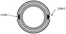
在一个实施例中,内电极210是片状结构。绝缘层220和外电极230是环状结构。一个冲击波电极组件200中包括多个内电极210,绝缘层220包括多个第一孔222,外电极230包括多个第二孔232。其中,内电极210、第一孔222以及第二孔232的数量相等。实际手术过程中,可能存在多处钙化病灶需要处理,因此可以采用具有多个内电极210的冲击波电极组件200,从而在冲击波球囊导管装置100上构建多个放电区域。一方面提高了冲击波球囊导管装置100同时处理多处钙化病灶的能力,另一方面,可能提高冲击波在内管110周向空间上分布的均匀性,从而有利于钙化病变的处理。以下将这种具有多个内电极210结构的冲击波电极组件200称为“冲击波多电极组件”。换句话说,冲击波多电极组件是根据本公开的冲击波电极组件200的一个示例。图6示出了设置有冲击波两电极组件的冲击波球囊导管装置100的截面示意图。如图所示,冲击波两电极组件的两个内电极210-1和210-2设置在内管外,两个内电极210-1和210-2的朝向呈180度。此外,可根据待处理钙化病灶的实际位置分布情况,对冲击波多电极组件的多个内电极210 在内管110周向上的分布进行相应调整,本公开对此不作限制。In one embodiment, the
在一个实施例中,在冲击波球囊导管装置100中,沿内管110的轴向间隔布置有多个冲击波多电极组件。如果要处理的钙化病灶有多个,并且间隔一定距离。若冲击波球囊导管装置100采用单个冲击波多电极组件,则需要将冲击波球囊导管装置100输送到不同钙化病灶的位置上进行逐个处理,操作不便。因此针对上述情况,可以采用具有沿内管110的轴向间隔布置的多个冲击波多电极组件200的冲击波球囊导管装置100。在一个实施例中,多个冲击波多电极组件200串联布置。图7示出了具有两个冲击波两电极组件 200的冲击波球囊导管装置100的示意图。同时根据待处理钙化病灶的实际位置分布,对不同冲击波电极组件200在内管110轴向上的分布进行相应调整,本公开对此不作限制。如图7、图8A和图8B所示,第一冲击波两电极组件200A固定在内管110上,与之间隔的第二冲击波两电极组件200B相对第一冲击波两电极组件200A沿内管110周向旋转90角度,从而第一冲击波两电极组件的第一孔222A-1与第二冲击波两电极组件的第一孔222B-1的朝向呈90角度。相应地,在布置有多个冲击波两电极组件的冲击波球囊导管装置100中,根据实际需要,可以将相邻的冲击波两电极组件的第一孔222的朝向布置成任意角度,本公开对此不作限制。例如,三个冲击波两电极组件的第一孔222的朝向依次间隔60度分布,四个冲击波两电极组件的第一孔222的朝向依次间隔45度分布。此外,在布置有多个冲击波多电极组件的冲击波球囊导管装置100中,也可以进行与上述方法相似的布置,这里不再赘述。In one embodiment, in the shock wave balloon catheter device 100 , a plurality of shock wave multi-electrode assemblies are arranged at intervals along the axial direction of the
根据发明人实验研究,根据本发明的实施例的双层球囊120对提高冲击波电极组件200发出冲击波的声压强度具有有益效果。According to the inventor's experimental research, the double-
图9显示球囊的不同充盈压力下冲击波电极组件200发出的冲击波的声压强度。在固定脉冲电压的条件下,选用水为充盈液体介质,双层球囊120 内充盈压力从0atm增长到20atm,产生冲击波的声压强度呈现出先增长后降低的趋势。这主要是以下两方面的共同作用。一方面,充盈压力的持续增大,致使水介质对冲击波击穿通道形成的阻碍作用增强,导致冲击波击穿放电能量损耗增多,冲击波产生的声压强度降低。另一方面,从冲击波传递的角度来说,充盈压力的增加在一定程度上使得冲击波的衰减减弱,这对冲击波传递产生促进作用。当充盈压力较低时(0atm-6atm),充盈压力促进冲击波传递的作用强于对冲击波击穿的抑制作用。因此,冲击波的声压强度随着充盈压力的升高而增大,当充盈压力为6atm时,冲击波声压强度最大,达到峰值。当充盈压力继续增大时(6atm-20atm),充盈压力促进冲击波传递的作用有限,导致充盈压力对冲击波击穿的抑制作用明显高于促进冲击波传递的作用,从而表现出冲击波声压强度逐步减弱的趋势。在每一组放电参数下均对应一个最优的充盈压力值,从而使得病灶致裂效果最好。FIG. 9 shows the sound pressure intensity of the shock wave emitted by the shock
根据本发明的实施例的双层球囊120在保证冲击波能够产生最佳声压强度的同时,还具有较高的充盈压力,双层球囊120和冲击波组件200协同作用,能够有效治疗钙化病变。脉冲冲击波在高能等离子体的驱动下作用于钙化病变。由于充盈水介质良好的传能特性,在钙化裂隙处产生振动效应。这造成原有水压裂隙和初始裂隙扩展和发育,最终裂隙相互贯通,形成宏观的贯通裂缝。在短时间内重复进行高压脉冲放电。钙化病变在充盈压力和高压放电形成的多次脉冲共同协同作用下,裂缝延展长度增加。裂缝的数量增多,进而更容易碎裂。原则上,在保证声压强度的条件下,选择更高的充盈压力,能够获得更高扩张力,从而有更好的钙化病变碎裂效果。The double-
本公开实施例的冲击波球囊导管装置100具有上述双层结构的球囊120 以及冲击波电极组件200的组合设计,这可以既满足该装置在高充盈压力下发射冲击波的要求,还可以保证球囊的贴壁效果。The shock wave balloon catheter device 100 of the embodiment of the present disclosure has the combined design of the
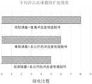
本公开的发明人使用石膏圈作为钙化模型,研究了以下三种情况下采用相同冲击波球囊导管装置100的扩张效果,记录不同条件下石膏圈的碎裂情况。在第一组实验中,冲击波电极组件200在0atm充盈压力下发射冲击波。在第二组实验中,冲击波球囊导管装置100只使用6atm的充盈压力。在第三组实验中,冲击波电极组件200在6atm充盈压力下发射冲击波。结果发现,第一组实验和第二组实验中的冲击波球囊导管装置100都无法使石膏圈碎裂。而在第三组实验中,在6atm充盈压力下,冲击波电极组件200发射数次冲击波即可使石膏圈碎裂。这些结果表明,球囊120扩张和冲击波的确存在协同作用。冲击波电极组件200在较高压力下发射冲击波,会更有利于钙化裂纹的产生,从而破坏钙化病变。The inventors of the present disclosure use the plaster circle as a calcification model to study the expansion effect of the same shock wave balloon catheter device 100 under the following three conditions, and record the fragmentation of the plaster circle under different conditions. In the first set of experiments, the shock
此外,本公开的发明人还研究了具有不同配置的冲击波球囊导管装置 100的扩张效果,如图10所示。扩张效果测试均是在相同脉冲电压和相同充盈压力条件下进行。测试结果显示,采用本公开的冲击波球囊导管装置100,相比较软质球囊,双层球囊可以在更少的放电次数下击碎钙化模型;相比较不设置有凸起引脚结构的冲击波电极组件,在相同脉冲电压条件下,本公开实施例的冲击波电极组件200可以在更少的放电次数下击碎钙化模型。双层球囊由于独特的结构特征,一方面,在有效增大球囊的爆破压的同时,使得球囊具有较好的顺应性和贴壁性,另一方面,在使球囊具有相同爆破压的前提下,与软质球囊相比,使用双层结构的球囊壁厚更小,较小的壁厚减少了冲击波能量在传递过程中的损耗,使更多的能量能够传递至病变,从而更好的击碎钙化斑块。这种布置有冲击波电极组件200以及双层结构的球囊120 的冲击波球囊导管装置100能够有效的击碎钙化斑块,并且具有优异的扩张效果,可以应用于血管成形术中。In addition, the inventors of the present disclosure have also studied the dilation effect of shock wave balloon catheter devices 100 with different configurations, as shown in FIG. 10 . The expansion effect tests were all carried out under the same pulse voltage and the same filling pressure. The test results show that, using the shock wave balloon catheter device 100 of the present disclosure, the double-layer balloon can crush the calcification model with fewer discharge times than the soft balloon; The shock wave electrode assembly, under the condition of the same pulse voltage, the shock
根据本公开的冲击波球囊导管装置100因其独特的双层球囊设计具有较高的爆破压,可达20个标准大气压。在发射的冲击波使得病变产生裂纹后,可以直接对球囊120进行进一步扩张。较高的扩张压力避免了传统冲击波球囊导管装置扩张不足而需要再次置入高压球囊配合使用的情况。高效稳定的冲击波电极组件200为整个冲击波导管装置100提供了较高的声压强度,球囊120的双层结构提供了足够的扩张压力。两者协同作用能够充分扩张病变,打通血管。从而减少手术步骤,缩短手术时间,并减少手术并发症的风险。The shock wave balloon catheter device 100 according to the present disclosure has a high burst pressure, up to 20 standard atmospheres, due to its unique double-layered balloon design. The
此外,本发明人还提出一种医疗设备。如图11所示,该医疗设备包括上述的冲击波球囊导管装置100、高压发生器310和导管座330。上述冲击波球囊导管装置100还包括连接导线320,该连接导线320的远端通过导管座330 与冲击波电极组件200连接。连接导线320的近端与高压发生器310连接。高压发生器需满足如下参数要求:高压发生器的脉冲电压为500V~10kV,脉冲电压宽度为200ns~20μs;高压发生器的脉冲电流为50A~400A,脉冲电流宽度为10ns~2μs。在一个实施例中,每个冲击波电极组件200产生冲击波的声压强度为2Mpa~20Mpa,放电频率为0.1Hz~10Hz。在一个实施例中,连接导线320包含第一电极导线和第二电极导线,第一电极导线与内电极210相连,第二电极导线与外电极230相连。In addition, the present inventor also proposes a medical device. As shown in FIG. 11 , the medical equipment includes the above-mentioned shock wave balloon catheter device 100 , a high-
在实际工作中,电流通过第一电极导线传输到内电极210,内电极210 通过充盈的导电流体与外电极230构成回路。高压脉冲将导电流体击穿,在第一孔222的轴向方向上产生冲击波。然后,电流传输至外电极230,并沿第二电极导线回到高压发生器。冲击波电极组件200产生的冲击波通过球囊 120内部的液体的传播,冲击球囊壁和钙化区域。反复的脉冲可以破坏钙化灶的结构,扩张狭窄血管,而不损伤周围的软组织。并且,在本公开实施例的医疗设备中,球囊采用双层结构设计,在有效增大球囊的爆破压的同时,使得球囊具有较好的顺应性和贴壁性。而且,冲击波球囊导管装置还能产生更高的声压强度。通过高声压强度与高充盈压力的协同作用,可更容易粉碎钙化斑块。因而本公开实施例的医疗设备能更有效地破坏病变血管壁上附着的钙化病灶结构,提高对堵塞病变的治疗效果。In actual operation, the current is transmitted to the
有以下几点需要说明:The following points need to be noted:
(1)本公开实施例附图只涉及到本公开实施例涉及到的结构,其他结构可参考通常设计。(1) The drawings of the embodiments of the present disclosure only relate to the structures involved in the embodiments of the present disclosure, and other structures may refer to general designs.
(2)在不冲突的情况下,本公开的实施例及实施例中的特征可以相互组合以得到新的实施例。(2) The embodiments of the present disclosure and features in the embodiments may be combined with each other to obtain new embodiments without conflict.
以上,仅为本公开的具体实施方式,但本公开的保护范围并不局限于此,本公开的保护范围应以权利要求的保护范围为准。The above are only specific embodiments of the present disclosure, but the protection scope of the present disclosure is not limited thereto, and the protection scope of the present disclosure should be subject to the protection scope of the claims.
Claims (13)
Priority Applications (2)
| Application Number | Priority Date | Filing Date | Title |
|---|---|---|---|
| CN202210172787.4ACN114533198A (en) | 2022-02-24 | 2022-02-24 | Shock wave balloon catheter device and medical equipment |
| PCT/CN2023/077276WO2023160505A1 (en) | 2022-02-24 | 2023-02-21 | Shock-wave balloon catheter device and medical apparatus |
Applications Claiming Priority (1)
| Application Number | Priority Date | Filing Date | Title |
|---|---|---|---|
| CN202210172787.4ACN114533198A (en) | 2022-02-24 | 2022-02-24 | Shock wave balloon catheter device and medical equipment |
Publications (1)
| Publication Number | Publication Date |
|---|---|
| CN114533198Atrue CN114533198A (en) | 2022-05-27 |
Family
ID=81677377
Family Applications (1)
| Application Number | Title | Priority Date | Filing Date |
|---|---|---|---|
| CN202210172787.4APendingCN114533198A (en) | 2022-02-24 | 2022-02-24 | Shock wave balloon catheter device and medical equipment |
Country Status (2)
| Country | Link |
|---|---|
| CN (1) | CN114533198A (en) |
| WO (1) | WO2023160505A1 (en) |
Cited By (11)
| Publication number | Priority date | Publication date | Assignee | Title |
|---|---|---|---|---|
| CN114983521A (en)* | 2022-06-10 | 2022-09-02 | 飞依诺科技股份有限公司 | Shock wave lithotripsy pipe and shock wave lithotripsy pipe system with same |
| CN115192872A (en)* | 2022-07-18 | 2022-10-18 | 深圳市赛禾医疗技术有限公司 | Balloon catheter and shock wave device |
| CN115192871A (en)* | 2022-07-11 | 2022-10-18 | 上海百心安生物技术股份有限公司 | Pulse balloon dilatation catheter with ultrasonic detection function |
| CN115245373A (en)* | 2022-09-26 | 2022-10-28 | 上海百心安生物技术股份有限公司 | Pulse sacculus expansion pipe of even fragmentation |
| CN115569292A (en)* | 2022-07-11 | 2023-01-06 | 上海百心安生物技术股份有限公司 | Pulse balloon dilatation catheter with optical interference tomography capability |
| CN115644989A (en)* | 2022-12-29 | 2023-01-31 | 南京沃福曼医疗科技有限公司 | Multi-channel pulse high-voltage parameter controllable shock wave lithotripsy balloon imaging system and catheter thereof |
| CN115644983A (en)* | 2022-10-17 | 2023-01-31 | 翌铭科技(广州)有限公司 | Blood vessel ultrasonic expansion integrated device |
| CN115844487A (en)* | 2022-11-22 | 2023-03-28 | 上海精诚医疗器械有限公司 | Shock wave balloon catheter and shock wave device |
| WO2023160505A1 (en)* | 2022-02-24 | 2023-08-31 | 上海蓝帆博元医疗科技有限公司 | Shock-wave balloon catheter device and medical apparatus |
| WO2024021159A1 (en)* | 2022-07-26 | 2024-02-01 | 深圳高性能医疗器械国家研究院有限公司 | Burst wave balloon catheter |
| WO2024088366A1 (en)* | 2022-10-27 | 2024-05-02 | 上海蓝帆博奥医疗科技有限公司 | Balloon device for shock wave medical device, and shock wave medical device |
Citations (8)
| Publication number | Priority date | Publication date | Assignee | Title |
|---|---|---|---|---|
| US20160058981A1 (en)* | 2005-12-20 | 2016-03-03 | Abbott Cardiovascular Systems Inc. | Non-compliant multilayered balloon for a catheter |
| CN105919701A (en)* | 2016-05-24 | 2016-09-07 | 江苏大学 | Stepped balloon |
| CN106178231A (en)* | 2016-08-03 | 2016-12-07 | 武汉福脉医疗科技有限公司 | Medical double-deck high pressure resistant sacculus and preparation method thereof |
| US20170035498A1 (en)* | 2015-08-03 | 2017-02-09 | Boston Scientific Scimed, Inc. | Systems and methods for mapping and ablation in the bladder |
| CN110368061A (en)* | 2019-08-06 | 2019-10-25 | 沛嘉医疗科技(苏州)有限公司 | A kind of shock wave heart valve interventional therapy transportation system |
| CN112439122A (en)* | 2019-09-05 | 2021-03-05 | 尤东侠 | Balloon dilatation catheter |
| CN113855163A (en)* | 2021-11-09 | 2021-12-31 | 上海蓝帆博元医疗科技有限公司 | Shock wave electrode assembly, balloon catheter device and medical equipment |
| CN217853181U (en)* | 2022-02-24 | 2022-11-22 | 上海蓝帆博元医疗科技有限公司 | Shock wave sacculus pipe device and medical equipment |
Family Cites Families (3)
| Publication number | Priority date | Publication date | Assignee | Title |
|---|---|---|---|---|
| WO2014133708A1 (en)* | 2013-02-26 | 2014-09-04 | Cook Medical Technologies Llc | Balloon catheter |
| EP3240603B1 (en)* | 2014-12-30 | 2019-05-01 | The Spectranetics Corporation | Laser-induced fluid filled balloon catheter |
| CN114533198A (en)* | 2022-02-24 | 2022-05-27 | 上海蓝帆博元医疗科技有限公司 | Shock wave balloon catheter device and medical equipment |
- 2022
- 2022-02-24CNCN202210172787.4Apatent/CN114533198A/enactivePending
- 2023
- 2023-02-21WOPCT/CN2023/077276patent/WO2023160505A1/ennot_activeCeased
Patent Citations (8)
| Publication number | Priority date | Publication date | Assignee | Title |
|---|---|---|---|---|
| US20160058981A1 (en)* | 2005-12-20 | 2016-03-03 | Abbott Cardiovascular Systems Inc. | Non-compliant multilayered balloon for a catheter |
| US20170035498A1 (en)* | 2015-08-03 | 2017-02-09 | Boston Scientific Scimed, Inc. | Systems and methods for mapping and ablation in the bladder |
| CN105919701A (en)* | 2016-05-24 | 2016-09-07 | 江苏大学 | Stepped balloon |
| CN106178231A (en)* | 2016-08-03 | 2016-12-07 | 武汉福脉医疗科技有限公司 | Medical double-deck high pressure resistant sacculus and preparation method thereof |
| CN110368061A (en)* | 2019-08-06 | 2019-10-25 | 沛嘉医疗科技(苏州)有限公司 | A kind of shock wave heart valve interventional therapy transportation system |
| CN112439122A (en)* | 2019-09-05 | 2021-03-05 | 尤东侠 | Balloon dilatation catheter |
| CN113855163A (en)* | 2021-11-09 | 2021-12-31 | 上海蓝帆博元医疗科技有限公司 | Shock wave electrode assembly, balloon catheter device and medical equipment |
| CN217853181U (en)* | 2022-02-24 | 2022-11-22 | 上海蓝帆博元医疗科技有限公司 | Shock wave sacculus pipe device and medical equipment |
Cited By (15)
| Publication number | Priority date | Publication date | Assignee | Title |
|---|---|---|---|---|
| WO2023160505A1 (en)* | 2022-02-24 | 2023-08-31 | 上海蓝帆博元医疗科技有限公司 | Shock-wave balloon catheter device and medical apparatus |
| CN114983521B (en)* | 2022-06-10 | 2025-08-29 | 飞依诺科技股份有限公司 | Shock wave lithotripsy catheter and shock wave lithotripsy catheter system having the same |
| CN114983521A (en)* | 2022-06-10 | 2022-09-02 | 飞依诺科技股份有限公司 | Shock wave lithotripsy pipe and shock wave lithotripsy pipe system with same |
| CN115192871A (en)* | 2022-07-11 | 2022-10-18 | 上海百心安生物技术股份有限公司 | Pulse balloon dilatation catheter with ultrasonic detection function |
| CN115569292A (en)* | 2022-07-11 | 2023-01-06 | 上海百心安生物技术股份有限公司 | Pulse balloon dilatation catheter with optical interference tomography capability |
| CN115192872B (en)* | 2022-07-18 | 2023-09-26 | 深圳市赛禾医疗技术有限公司 | Balloon catheter and shock wave device |
| CN115192872A (en)* | 2022-07-18 | 2022-10-18 | 深圳市赛禾医疗技术有限公司 | Balloon catheter and shock wave device |
| WO2024021159A1 (en)* | 2022-07-26 | 2024-02-01 | 深圳高性能医疗器械国家研究院有限公司 | Burst wave balloon catheter |
| CN115245373A (en)* | 2022-09-26 | 2022-10-28 | 上海百心安生物技术股份有限公司 | Pulse sacculus expansion pipe of even fragmentation |
| CN115644983A (en)* | 2022-10-17 | 2023-01-31 | 翌铭科技(广州)有限公司 | Blood vessel ultrasonic expansion integrated device |
| WO2024088366A1 (en)* | 2022-10-27 | 2024-05-02 | 上海蓝帆博奥医疗科技有限公司 | Balloon device for shock wave medical device, and shock wave medical device |
| CN115844487A (en)* | 2022-11-22 | 2023-03-28 | 上海精诚医疗器械有限公司 | Shock wave balloon catheter and shock wave device |
| CN115644989B (en)* | 2022-12-29 | 2023-09-15 | 南京沃福曼医疗科技有限公司 | Multi-channel impulse high-pressure parameter controllable shock wave lithotriptic balloon imaging system and catheter thereof |
| WO2024140073A1 (en)* | 2022-12-29 | 2024-07-04 | 南京沃福曼医疗科技有限公司 | Multi-channel pulse high-voltage parameter-controllable shock wave lithotripsy balloon imaging system and catheter thereof |
| CN115644989A (en)* | 2022-12-29 | 2023-01-31 | 南京沃福曼医疗科技有限公司 | Multi-channel pulse high-voltage parameter controllable shock wave lithotripsy balloon imaging system and catheter thereof |
Also Published As
| Publication number | Publication date |
|---|---|
| WO2023160505A1 (en) | 2023-08-31 |
Similar Documents
| Publication | Publication Date | Title |
|---|---|---|
| CN114533198A (en) | Shock wave balloon catheter device and medical equipment | |
| CN217853181U (en) | Shock wave sacculus pipe device and medical equipment | |
| US20240407796A1 (en) | Shockwave valvuloplasty catheter system | |
| US12114923B2 (en) | Shock wave balloon catheter with multiple shock wave sources | |
| CN113842190B (en) | Electrode Balloon Catheter | |
| EP4431032A1 (en) | Shock wave electrode assembly, balloon catheter apparatus, and medical device | |
| JP6529565B2 (en) | Shock wave balloon catheter device | |
| CN214907695U (en) | Pressure wave sacculus pipe and medical instrument | |
| WO2023071427A1 (en) | Intravascular calcified plaque impact fracture device | |
| CN115192122A (en) | Shockwave Balloon Catheter Device | |
| CN115778485A (en) | Shock wave generating device, shock wave generating system and method | |
| CN115363692A (en) | Shock wave filament system | |
| WO2020192146A1 (en) | Ultrasound balloon catheter assembly, catheter system and usage method | |
| CN222265917U (en) | Shock wave balloon catheter and shock wave generating device | |
| CN119055315A (en) | A nested double-balloon shock wave catheter | |
| CN117796894A (en) | Pulse electric field ablation device for esophagus cancer | |
| CN119423916A (en) | A shock wave multi-balloon catheter | |
| CN119949952A (en) | Intravascular shock wave catheter and medical device |
Legal Events
| Date | Code | Title | Description |
|---|---|---|---|
| PB01 | Publication | ||
| PB01 | Publication | ||
| SE01 | Entry into force of request for substantive examination | ||
| SE01 | Entry into force of request for substantive examination |