CN114522857A - Dynamic coating machine for disc electrode - Google Patents
Dynamic coating machine for disc electrodeDownload PDFInfo
- Publication number
- CN114522857A CN114522857ACN202210261825.3ACN202210261825ACN114522857ACN 114522857 ACN114522857 ACN 114522857ACN 202210261825 ACN202210261825 ACN 202210261825ACN 114522857 ACN114522857 ACN 114522857A
- Authority
- CN
- China
- Prior art keywords
- electrode
- disc
- bushing
- coating machine
- dynamic coating
- Prior art date
- Legal status (The legal status is an assumption and is not a legal conclusion. Google has not performed a legal analysis and makes no representation as to the accuracy of the status listed.)
- Pending
Links
Images


Classifications
- B—PERFORMING OPERATIONS; TRANSPORTING
- B05—SPRAYING OR ATOMISING IN GENERAL; APPLYING FLUENT MATERIALS TO SURFACES, IN GENERAL
- B05C—APPARATUS FOR APPLYING FLUENT MATERIALS TO SURFACES, IN GENERAL
- B05C11/00—Component parts, details or accessories not specifically provided for in groups B05C1/00 - B05C9/00
- B05C11/02—Apparatus for spreading or distributing liquids or other fluent materials already applied to a surface ; Controlling means therefor; Control of the thickness of a coating by spreading or distributing liquids or other fluent materials already applied to the coated surface
- B05C11/08—Spreading liquid or other fluent material by manipulating the work, e.g. tilting
- B—PERFORMING OPERATIONS; TRANSPORTING
- B05—SPRAYING OR ATOMISING IN GENERAL; APPLYING FLUENT MATERIALS TO SURFACES, IN GENERAL
- B05C—APPARATUS FOR APPLYING FLUENT MATERIALS TO SURFACES, IN GENERAL
- B05C13/00—Means for manipulating or holding work, e.g. for separate articles
- B05C13/02—Means for manipulating or holding work, e.g. for separate articles for particular articles
- Y—GENERAL TAGGING OF NEW TECHNOLOGICAL DEVELOPMENTS; GENERAL TAGGING OF CROSS-SECTIONAL TECHNOLOGIES SPANNING OVER SEVERAL SECTIONS OF THE IPC; TECHNICAL SUBJECTS COVERED BY FORMER USPC CROSS-REFERENCE ART COLLECTIONS [XRACs] AND DIGESTS
- Y02—TECHNOLOGIES OR APPLICATIONS FOR MITIGATION OR ADAPTATION AGAINST CLIMATE CHANGE
- Y02E—REDUCTION OF GREENHOUSE GAS [GHG] EMISSIONS, RELATED TO ENERGY GENERATION, TRANSMISSION OR DISTRIBUTION
- Y02E60/00—Enabling technologies; Technologies with a potential or indirect contribution to GHG emissions mitigation
- Y02E60/30—Hydrogen technology
- Y02E60/50—Fuel cells
Landscapes
- Inert Electrodes (AREA)
Abstract
Translated fromChinese
Description
Translated fromChinese技术领域technical field
本发明属于表面液体涂覆技术领域,具体涉及一种圆盘电极动态涂覆机。The invention belongs to the technical field of surface liquid coating, and in particular relates to a dynamic coating machine for disk electrodes.
背景技术Background technique
电化学催化剂的测试是电化学研究领域中经常做的实验,用于测试其电化学性能,如催化材料的活性和稳定性。在传统使用过程中,被测试的固体催化剂样品需要首先超声分散在特定溶剂和粘结剂的混合液中,然后静态滴涂在圆盘电极的表面,待溶剂蒸发后,固体样品将分布在圆盘电极表面。由于液体毛细力、溶剂表面张力、以及蒸发速率的影响,催化剂样品在静态滴涂的圆盘电极表面难以获得均匀的厚度分布,各处往往会呈现较大的厚度分布差别,继而影响电化学测试的结果,无法达到电极反应的极限电流密度。厚度不均的催化剂层样品会降低电化学测试的数据一致性,使数据难以重复,降低数据的可靠性。同时,静态滴涂获得的催化剂层厚度不均的问题,也会导致催化剂在测试中表现出更低的活性与稳定性。因此,如何实现催化剂样品在涂覆后能够在圆盘电极表面均匀分布,达到催化剂层各处厚度均匀的状态,对于保证电化学测试结果的一致性、重复性和可靠性具有重要的意义。Testing of electrochemical catalysts is a frequently done experiment in the field of electrochemical research to test their electrochemical properties, such as the activity and stability of catalytic materials. In the traditional use process, the tested solid catalyst sample needs to be ultrasonically dispersed in a mixture of a specific solvent and a binder, and then statically drop-coated on the surface of the disc electrode. After the solvent evaporates, the solid sample will be distributed in the circular disk electrode surface. Due to the influence of liquid capillary force, solvent surface tension, and evaporation rate, it is difficult for catalyst samples to obtain uniform thickness distribution on the surface of the statically drop-coated disk electrode, and there are often large thickness distribution differences everywhere, which in turn affects the electrochemical test. As a result, the limiting current density of the electrode reaction cannot be reached. The catalyst layer samples with uneven thickness will reduce the data consistency of the electrochemical test, make the data difficult to repeat, and reduce the reliability of the data. At the same time, the problem of uneven thickness of the catalyst layer obtained by static drop coating will also cause the catalyst to show lower activity and stability in the test. Therefore, how to realize the uniform distribution of the catalyst samples on the surface of the disk electrode after coating, so as to achieve a state of uniform thickness everywhere in the catalyst layer, is of great significance to ensure the consistency, repeatability and reliability of the electrochemical test results.
发明内容SUMMARY OF THE INVENTION
本发明针对上述问题提供了一种圆盘电极动态涂覆机。In view of the above problems, the present invention provides a disk electrode dynamic coating machine.
为达到上述目的本发明采用了以下技术方案:For achieving the above object, the present invention has adopted the following technical solutions:
一种圆盘电极动态涂覆机,包括动力装置和旋转底座,所述动力装置用于带动旋转底座旋转,所述旋转底座用于卡装圆盘电极,并带动圆盘电极旋转,从而完成圆盘电极的均匀涂覆工作。A disk electrode dynamic coating machine, including a power device and a rotating base, the power device is used to drive the rotating base to rotate, and the rotating base is used to clamp the disk electrode and drive the disk electrode to rotate, so as to complete the circle. Uniform coating of disk electrodes works.
进一步,还包括外壳机体,所述动力装置安装在外壳机体内部。Further, a casing body is also included, and the power device is installed inside the casing body.
再进一步,所述旋转底座包括电极衬套,所述电极衬套用于卡装圆盘电极,并带动圆盘电极旋转。Still further, the rotating base includes an electrode bushing, and the electrode bushing is used for clamping the disk electrode and driving the disk electrode to rotate.
更进一步,所述旋转底座还包括轴承座,所述轴承座安装在外壳机体上,在所述轴承座内安装有轴承,所述电极衬套安装于轴承内部。Further, the rotating base further includes a bearing seat, the bearing seat is installed on the housing body, a bearing is installed in the bearing seat, and the electrode bushing is installed inside the bearing.
更进一步,所述轴承有两组,呈轴向安装于轴承座内,通过两组轴承对电极衬套进行支撑,以保证电极衬套旋转时的同轴度,有效提高电极衬套旋转的平稳性。Further, there are two sets of the bearings, which are axially installed in the bearing seat, and the electrode bushing is supported by the two sets of bearings, so as to ensure the coaxiality of the electrode bushing when it rotates, and effectively improve the stable rotation of the electrode bushing. sex.
更进一步,所述动力装置通过软传动的方式带动电极衬套旋转。Furthermore, the power device drives the electrode bushing to rotate by means of soft transmission.
更进一步,在所述动力装置的输出端安装有旋转盘,在所述旋转盘的上方设置有传动底盘,所述旋转盘通过弹簧与传动底盘连接,通过弹簧进行动力传递可以消除动力装置震动和动力装置与电极衬套安装位置不完全同轴造成的偏心运动影响,使得电极衬套在旋转的同时更佳平稳。Further, a rotating disc is installed at the output end of the power unit, and a transmission chassis is arranged above the rotating disc. The rotating disc is connected with the transmission chassis through a spring, and the power transmission through the spring can eliminate the vibration and the vibration of the power unit. The eccentric motion caused by the incomplete coaxial installation position of the power device and the electrode bushing makes the electrode bushing more stable while rotating.
更进一步,在所述传动底盘与电极衬套通过过盈配合的嵌合方式连接。Furthermore, the transmission chassis and the electrode bushing are connected by a fitting manner of interference fit.
更进一步,在所述电极衬套的底部设置有若干沉孔,在所述传动底盘上设置有若干与沉孔一一对应的凸台。Furthermore, a number of countersinks are arranged at the bottom of the electrode bushing, and a number of bosses corresponding to the countersunk holes are arranged on the transmission chassis.
更进一步,所述传动底盘与电极衬套为一体结构。Furthermore, the transmission chassis and the electrode bushing are integral structures.
更进一步,所述电极衬套采用塑料材制制成,可以有效避免接触污染带来对圆盘电极的实验影响。Furthermore, the electrode bushing is made of plastic material, which can effectively avoid the experimental influence on the disk electrode caused by contact pollution.
更进一步,所述电极衬套采用PTFE聚四氟乙烯材料制成。Further, the electrode bushing is made of PTFE polytetrafluoroethylene material.
更进一步,在所述传动底盘的上表面设置有用于与圆盘电极限位卡装的限位台肩。Furthermore, the upper surface of the transmission chassis is provided with a limit shoulder for clamping with the electric limit of the disc.
更进一步,还包括控制组件,用于控制动力装置的旋转速度。Still further, a control assembly is included for controlling the rotational speed of the power plant.
与现有技术相比本发明具有以下优点:Compared with the prior art, the present invention has the following advantages:
1、本发明通过动力装置带动圆盘电极匀速旋转,利用离心力作用与液体表面张力、毛细力、蒸发速率相匹配,实现催化剂分散液在圆盘电极表面均匀分布,最终实现催化剂层在圆盘电极上的均匀涂覆;1. The present invention drives the disk electrode to rotate at a uniform speed through a power device, and uses centrifugal force to match the surface tension, capillary force, and evaporation rate of the liquid to achieve uniform distribution of the catalyst dispersion on the surface of the disk electrode, and finally realize the catalyst layer on the disk electrode. uniform coating on the
2、本发明通过将电极衬套嵌套于双轴承底座的结构,提高了电极衬套旋转时,圆盘电极的转动同轴性和平稳性,从而保证电极涂覆液体样品时所获得的催化剂层厚度均匀性;2. The present invention improves the rotation coaxiality and smoothness of the disk electrode when the electrode bushing rotates by nesting the electrode bushing in the double-bearing base, thereby ensuring the catalyst obtained when the electrode is coated with the liquid sample. Layer thickness uniformity;
3、本发明通过设置软传动结构,降低了动力装置输出端的震动和轴向位置偏差,从而提高了电极衬套旋转时的同轴度,保证了实验数据不受外部因素影响的一致性;3. The present invention reduces the vibration of the output end of the power device and the axial position deviation by setting the soft transmission structure, thereby improving the coaxiality of the electrode bushing when rotating, and ensuring the consistency of the experimental data not affected by external factors;
4、本发明通过传动底盘与电极衬套的过盈配合和凸台及沉孔结构,将旋转动力更稳定的传递给电极衬套,提高了传动的可靠性。4. The present invention transmits the rotational power to the electrode bushing more stably through the interference fit between the transmission chassis and the electrode bushing and the structure of the boss and countersunk holes, thereby improving the reliability of the transmission.
附图说明Description of drawings
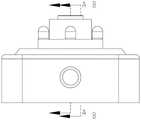
图1为本发明的结构示意图;Fig. 1 is the structural representation of the present invention;
图2为本发明的正视图;Fig. 2 is the front view of the present invention;
图3为本发明图2中A-A截面的剖视图;Fig. 3 is the sectional view of A-A section in Fig. 2 of the present invention;
图4为本发明图3中圈A的局部放大图;Fig. 4 is a partial enlarged view of circle A in Fig. 3 of the present invention;
图5为本发明图2中B-B截面的剖视图;Fig. 5 is the sectional view of the B-B section in Fig. 2 of the present invention;
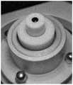
图6为圆盘电极和其工作位置示意图;Fig. 6 is the schematic diagram of disk electrode and its working position;
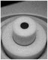
图7为圆盘电极涂覆示意图;7 is a schematic diagram of disk electrode coating;
图8为圆盘电极表面催化剂分散液静态图;Fig. 8 is the static diagram of the catalyst dispersion liquid on the surface of the disk electrode;
图9为圆盘电极表面催化剂分散液蒸干图;Fig. 9 is the evaporation-drying diagram of the catalyst dispersion liquid on the surface of the disk electrode;
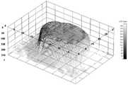
图10为采用本发明进行动态涂覆后催化剂表面的分布图;Fig. 10 is the distribution diagram of the catalyst surface after dynamic coating using the present invention;
图11为采用静态滴涂方法制备的电极上催化剂表面的分布图;Fig. 11 is the distribution diagram of the catalyst surface on the electrode prepared by the static drop coating method;
图12为动态涂覆和静态滴涂的电极极化曲线半波电位图;Figure 12 is a half-wave potential diagram of electrode polarization curves of dynamic coating and static drop coating;
图13为静态滴涂的五组重复性实验电极极化曲线图;Fig. 13 is the electrode polarization curve diagram of five groups of repetitive experiments of static drop coating;
图14为动态涂覆的五组重复性实验电极极化曲线图;Fig. 14 is the electrode polarization curve diagram of five groups of repetitive experiments of dynamic coating;
图中,动力装置—1、旋转底座—2、外壳机体—3、旋转盘—4、磁铁—5、传动底盘—6、弹簧—7、控制组件—8、电极衬套—201、轴承座—202、轴承—203。In the figure, power unit-1, rotating base-2, shell body-3, rotating disc-4, magnet-5, transmission chassis-6, spring-7, control assembly-8, electrode bushing-201, bearing seat- 202. Bearing-203.
具体实施方式Detailed ways
为了进一步阐述本发明的技术方案,下面通过实施例对本发明进行进一步说明。In order to further illustrate the technical solutions of the present invention, the present invention will be further described below through examples.
如图1至5所示,一种圆盘电极动态涂覆机,包括动力装置1、旋转底座2、外壳机体3和控制组件8,所述旋转底座2包括电极衬套201和轴承座202,所述轴承座202安装在外壳机体3上,在所述轴承座202内安装有轴承203,所述轴承203有两组,呈轴向安装于轴承座202内,通过两组轴承203对电极衬套201进行支撑,以保证电极衬套201旋转时的同轴度,有效提高电极衬套201旋转的平稳性,所述电极衬套201安装于轴承203内部,所述电极衬套201用于卡装圆盘电极,并带动圆盘电极旋转,所述电极衬套201采用PTFE聚四氟乙烯制成,可以有效避免接触污染带来对圆盘电极的实验影响,所述动力装置1安装在外壳机体3内部,在所述动力装置1的输出端安装有旋转盘4,在所述旋转盘4的上方设置有传动底盘6,所述旋转盘4通过弹簧7与传动底盘6连接,通过弹簧7进行动力传递可以消除动力装置1震动和动力装置1与电极衬套201安装位置不完全同轴造成的偏心运动影响,使得电极衬套201在旋转的同时更佳平稳,在所述传动底盘6与电极衬套201通过过盈配合的嵌合方式连接,在所述电极衬套201的底部设置有若干沉孔,在所述传动底盘6上设置有若干与沉孔一一对应的凸台,在所述传动底盘6的上表面设置有用于与圆盘电极限位卡装的限位台肩,所述控制组件8用于控制动力装置1的旋转速度。As shown in Figures 1 to 5, a disk electrode dynamic coating machine includes a
上述实施例中,传动底盘6还可与电极衬套201成一体结构。In the above embodiment, the
操作原理:将实验用圆盘电极嵌入电极衬套201内孔中至传动底盘6的台肩限位面,再通过外壳机体3中的控制组件8启动动力装置1,动力装置1输出末端的旋转盘4将旋转动力通过弹簧7传递给传动底盘6,传动底盘6驱使电极衬套201转动,同时电极衬套201在轴承203和轴承座201的双轴承座结构中旋转,并通过调整动力装置1的旋转速度,使电极衬套201中的圆盘电极匀速转动,从而使滴涂在圆盘电极上的液态样品在圆盘电极表面均匀铺展,干燥后的催化剂层在圆盘电极表面均匀分布,达到催化剂层各处厚度一致的涂覆状态。Operating principle: Insert the experimental disc electrode into the inner hole of the
如图10所示,使用本发明进行商用Pt/C催化剂的动态涂覆,可实现催化剂层呈现均匀分布,其表面分散层厚度方向Z轴上的差值在2-3nm,可以满足理想的旋转圆盘电极传质扩散控制反应模型;如图11所示,采用静态滴涂,催化剂覆盖不均,易团聚,其表面分散层厚度方向Z轴上的偏差在10-13nm,偏离理想传质模型,难以达到研究目的。As shown in Fig. 10, using the present invention for dynamic coating of commercial Pt/C catalysts, the catalyst layer can be uniformly distributed, and the difference in the Z-axis of the thickness direction of the surface dispersion layer is 2-3 nm, which can satisfy the ideal rotation The disc electrode mass transfer diffusion control reaction model; as shown in Figure 11, static drop coating is used, the catalyst is unevenly covered and easy to agglomerate, and the deviation of the Z axis in the thickness direction of the surface dispersion layer is 10-13nm, which deviates from the ideal mass transfer model. , it is difficult to achieve the research purpose.
根据氧还原极限电流密度公式:jD=0.62nFD02/3ν-1/6ω1/2C0*,可获得上述对商用Pt/C催化剂测试的理论极限电流密度值5.60mA cm-2。其中jD是极限电流密度,n为氧还原过程的电子转移数,F为法拉第常数(96485C/mol),C0*代表氧气在电解质溶液中饱和溶解度,D0代表电解质溶液的扩散系数,ω代表旋转的转速,ν为电解质中的动力学粘度。According to the oxygen reduction limiting current density formula: jD =0.62nFD02/3 ν-1/6 ω1/2 C0* , the theoretical limiting current density value of 5.60mA cm− 2 . where jD is the limiting current density, n is the electron transfer number in the oxygen reduction process, F is the Faraday constant (96485C/mol), C0* represents the saturated solubility of oxygen in the electrolyte solution, D0 represents the diffusion coefficient of the electrolyte solution, ω represents the rotational speed of rotation, and ν is the dynamic viscosity in the electrolyte.
如图12所示,对商用Pt/C催化剂的测试中,使用动态涂覆圆盘电极可测得半波电位0.88V,极限电流密度5.64mA cm-2;使用静态滴涂得到的圆盘电极,半波电位仅为0.85V,极限电流密度为5.18mA cm-2,均小于使用动态涂覆的电极数据。可见使用动态涂覆制备的电极可以达到理论极限电流密度,而使用静态滴涂制备的电极的极限电流密度低于理论值,无法满足研究需要。As shown in Figure 12, in the test of the commercial Pt/C catalyst, the half-wave potential of 0.88V and the limiting current density of 5.64mA cm-2 can be measured by using the dynamic coating disc electrode; the disc electrode obtained by static drop coating , the half-wave potential is only 0.85 V, and the limiting current density is 5.18 mA cm-2 , all of which are smaller than the data of electrodes using dynamic coating. It can be seen that the electrode prepared by dynamic coating can reach the theoretical limit current density, while the limit current density of the electrode prepared by static drop coating is lower than the theoretical value, which cannot meet the research needs.
图13、14所示分别为静态滴涂、动态涂覆的五组重复性电极测试极化曲线。根据对极化曲线数据的分析,可以获得半波电位值、质量活性、比表面积活性、极限电流密度数据,并进行统计分析,结果如表1、表2所示。Figures 13 and 14 show five groups of repetitive electrode test polarization curves of static drop coating and dynamic coating, respectively. According to the analysis of polarization curve data, data of half-wave potential value, mass activity, specific surface area activity, and limiting current density can be obtained, and statistical analysis is carried out. The results are shown in Table 1 and Table 2.
通过使用本发明动态涂覆电极装置制备的电极,其极化曲线的半波电位平均值为0.88V,高于静态滴涂电极的半波电位平均值(0.848V),且前者的相对标准偏差更小(表1、表2)。The electrode prepared by using the dynamic coating electrode device of the present invention has an average value of half-wave potential of its polarization curve of 0.88V, which is higher than that of a static drop-coated electrode (0.848V), and the relative standard deviation of the former is 0.88V. smaller (Table 1, Table 2).
同样,动态涂覆电极,测得氧还原极限电流密度平均值为5.62mA cm-2,高于传统静态滴涂电极测得的极限电流密度(5.24mA cm-2),且前者相对标准偏差更小,结果一致性更高,与理论极限电流密度更为接近(表1、表2)。Similarly, for the dynamic coating electrode, the average value of the oxygen reduction limiting current density measured is 5.62 mA cm-2 , which is higher than the limiting current density (5.24 mA cm-2 ) measured by the traditional static dispensing electrode, and the relative standard deviation of the former is higher. small, the results are more consistent and closer to the theoretical limiting current density (Table 1, Table 2).
一般使用比表面活性和质量比活性来评价催化剂的性能,通过计算使用本发明动态涂覆电极法测试时,商用20%Pt/C催化剂在0.9V电位下质量比活性和比表面活性的平均值分别为0.26Amg-1、0.30mA cm-2。使用传统静态滴涂电极测试时,商用20%Pt/C催化剂质量比活性和比表面活性的平均值分别为0.12A mg-1、0.24mA cm-2,低于使用使用本发明动态涂覆电极测得的结果,且前者质量比活性和比表面活性数据的相对标准偏差更小(表1、表2)。The specific surface activity and mass specific activity are generally used to evaluate the performance of the catalyst. By calculating the average value of the mass specific activity and specific surface activity of the commercial 20% Pt/C catalyst at a potential of 0.9V when tested by the dynamic coating electrode method of the present invention They are 0.26Amg-1 and 0.30mA cm-2 respectively. When using the traditional static drop coating electrode test, the average mass specific activity and specific surface activity of the commercial 20% Pt/C catalyst are 0.12A mg-1 and 0.24mA cm-2 , respectively, which are lower than those using the dynamic coating electrode of the present invention. The measured results, and the relative standard deviation of the former mass specific activity and specific surface activity data is smaller (Table 1, Table 2).
可见相比于静态滴涂电极,使用本发明动态涂覆方法制备的电极电化学性能数据一致性更高,重复性更佳,并可以达到理论极限电流密度,其半波电位、质量比活性、比表面活性相对静态滴涂电极的测量结果更高,因此使用圆盘电极动态涂覆装置制备的电极更优,更能够反应催化剂的催化性能。It can be seen that compared with the static drop coating electrode, the electrochemical performance data of the electrode prepared by the dynamic coating method of the present invention has higher consistency and better repeatability, and can reach the theoretical limit current density, and its half-wave potential, mass specific activity, The specific surface activity is higher than that of the static drop-coated electrode, so the electrode prepared using the disk electrode dynamic coating device is better and more capable of reflecting the catalytic performance of the catalyst.
表1为动态涂覆的五组重复性实验电极极化数据表Table 1 is the electrode polarization data table of five groups of repetitive experiments for dynamic coating

表1表2为静态滴涂的五组重复性实验电极极化数据表Table 1 and Table 2 are the electrode polarization data table of five groups of repetitive experiments of static drop coating

表2Table 2
以上显示和描述了本发明的主要特征和优点,对于本领域技术人员而言,显然本发明不限于上述示范性实施例的细节,而且在不背离本发明的精神或基本特征的情况下,能够以其他的具体形式实现本发明。因此,无论从哪一点来看,均应将实施例看作是示范性的,而且是非限制性的,本发明的范围由所附权利要求而不是上述说明限定,因此旨在将落在权利要求的等同要件的含义和范围内的所有变化囊括在本发明内。While the main features and advantages of the present invention have been shown and described above, it will be apparent to those skilled in the art that the present invention is not limited to the details of the above-described exemplary embodiments, but can, without departing from the spirit or essential characteristics of the present invention, be The present invention may be implemented in other specific forms. Therefore, the embodiments are to be regarded in all respects as illustrative and not restrictive, and the scope of the invention is to be defined by the appended claims rather than the foregoing description, which are therefore intended to fall within the scope of the claims. All changes within the meaning and scope of the equivalents of , are included in the present invention.
此外,应当理解,虽然本说明书按照实施方式加以描述,但并非每个实施方式仅包含一个独立的技术方案,说明书的这种叙述方式仅仅是为清楚起见,本领域技术人员应当将说明书作为一个整体,各实施例中的技术方案也可以经适当组合,形成本领域技术人员可以理解的其他实施方式。In addition, it should be understood that although this specification is described in terms of embodiments, not each embodiment only includes an independent technical solution, and this description in the specification is only for the sake of clarity, and those skilled in the art should take the specification as a whole , the technical solutions in each embodiment can also be appropriately combined to form other implementations that can be understood by those skilled in the art.
Claims (14)
Priority Applications (1)
| Application Number | Priority Date | Filing Date | Title |
|---|---|---|---|
| CN202210261825.3ACN114522857A (en) | 2022-03-16 | 2022-03-16 | Dynamic coating machine for disc electrode |
Applications Claiming Priority (1)
| Application Number | Priority Date | Filing Date | Title |
|---|---|---|---|
| CN202210261825.3ACN114522857A (en) | 2022-03-16 | 2022-03-16 | Dynamic coating machine for disc electrode |
Publications (1)
| Publication Number | Publication Date |
|---|---|
| CN114522857Atrue CN114522857A (en) | 2022-05-24 |
Family
ID=81626239
Family Applications (1)
| Application Number | Title | Priority Date | Filing Date |
|---|---|---|---|
| CN202210261825.3APendingCN114522857A (en) | 2022-03-16 | 2022-03-16 | Dynamic coating machine for disc electrode |
Country Status (1)
| Country | Link |
|---|---|
| CN (1) | CN114522857A (en) |
Citations (9)
| Publication number | Priority date | Publication date | Assignee | Title |
|---|---|---|---|---|
| JPH034961A (en)* | 1989-06-02 | 1991-01-10 | Tokyo Electron Ltd | Coating apparatus |
| US5656082A (en)* | 1994-04-04 | 1997-08-12 | Tatsumo Kabushiki Kaisha | Liquid applying apparatus utilizing centrifugal force |
| JP2001300400A (en)* | 2000-04-27 | 2001-10-30 | Dainippon Screen Mfg Co Ltd | Substrate treating device |
| CN1748874A (en)* | 2004-09-13 | 2006-03-22 | 肖特股份公司 | Method and apparatus for liquid application |
| CN102179348A (en)* | 2011-01-30 | 2011-09-14 | 上海拓引数码技术有限公司 | Glue spin coating device for blue-ray disc |
| CN202061773U (en)* | 2010-07-23 | 2011-12-07 | 向熙科技股份有限公司 | spin coating device |
| CN111482334A (en)* | 2020-05-22 | 2020-08-04 | 常州昂德工业装备科技有限公司 | Strip platinum electrode coating device |
| CN214412488U (en)* | 2020-12-21 | 2021-10-15 | 广州市施瑞医疗科技有限公司 | Multi-hole-site turntable device based on Hall sensor positioning |
| CN217369060U (en)* | 2022-03-16 | 2022-09-06 | 中国科学院山西煤炭化学研究所 | A disk electrode dynamic coating machine |
- 2022
- 2022-03-16CNCN202210261825.3Apatent/CN114522857A/enactivePending
Patent Citations (9)
| Publication number | Priority date | Publication date | Assignee | Title |
|---|---|---|---|---|
| JPH034961A (en)* | 1989-06-02 | 1991-01-10 | Tokyo Electron Ltd | Coating apparatus |
| US5656082A (en)* | 1994-04-04 | 1997-08-12 | Tatsumo Kabushiki Kaisha | Liquid applying apparatus utilizing centrifugal force |
| JP2001300400A (en)* | 2000-04-27 | 2001-10-30 | Dainippon Screen Mfg Co Ltd | Substrate treating device |
| CN1748874A (en)* | 2004-09-13 | 2006-03-22 | 肖特股份公司 | Method and apparatus for liquid application |
| CN202061773U (en)* | 2010-07-23 | 2011-12-07 | 向熙科技股份有限公司 | spin coating device |
| CN102179348A (en)* | 2011-01-30 | 2011-09-14 | 上海拓引数码技术有限公司 | Glue spin coating device for blue-ray disc |
| CN111482334A (en)* | 2020-05-22 | 2020-08-04 | 常州昂德工业装备科技有限公司 | Strip platinum electrode coating device |
| CN214412488U (en)* | 2020-12-21 | 2021-10-15 | 广州市施瑞医疗科技有限公司 | Multi-hole-site turntable device based on Hall sensor positioning |
| CN217369060U (en)* | 2022-03-16 | 2022-09-06 | 中国科学院山西煤炭化学研究所 | A disk electrode dynamic coating machine |
Similar Documents
| Publication | Publication Date | Title |
|---|---|---|
| CN217369060U (en) | A disk electrode dynamic coating machine | |
| Wen et al. | A single-walled carbon nanohorn-based miniature glucose/air biofuel cell for harvesting energy from soft drinks | |
| CN103782429A (en) | Method for producing catalyst ink, method for producing fuel cell, and fuel cell | |
| CN109742409A (en) | A kind of Hydrogen Proton exchange film fuel battery gas diffusion layers and preparation method thereof | |
| CN110459410A (en) | A preparation method of supercapacitor slurry and supercapacitor prepared by using supercapacitor slurry | |
| CN109580429A (en) | The viscoelastic test method of pulp of lithium ion battery | |
| CN109950560A (en) | Preparation method and application of biomass-based carbon fiber-supported nitrogen-doped carbon nanocomposite | |
| CN106124363A (en) | A kind of evaluating method of lithium ion battery plus-negative plate Stability of Slurry | |
| CN114522857A (en) | Dynamic coating machine for disc electrode | |
| TW202131544A (en) | Fuel cell electrode having high durability, method for manufacturing the same, and membrane-electrode assembly comprising the same | |
| CN101543810B (en) | Device and method for fuel battery coating | |
| CN113097510B (en) | A kind of preparation method of iron-based nitrogen-phosphorus co-doped porous carbon-oxygen reduction catalyst | |
| JP2005228601A (en) | Polymer electrolyte fuel cell | |
| JPWO2008007719A1 (en) | Enzyme electrode | |
| CN110034291A (en) | Silicon-carbon cathode material and preparation method thereof, battery | |
| Gao et al. | Electrocatalytic activity of carbon spheres towards NADH oxidation at low overpotential and its applications in biosensors and biofuel cells | |
| CN114335695B (en) | In-situ generation of silica composite solid polymer electrolyte and its application in lithium batteries | |
| Li et al. | Study on preparation process and durability of gas diffusion layer of proton exchange membrane fuel cell | |
| Xie et al. | Effects of electrostatic force and network structure on the stability of proton-exchange membrane fuel cell catalyst ink | |
| CN113237935B (en) | A kind of detection method of cysteine | |
| CN109075348A (en) | Method of manufacturing membrane electrode assembly, membrane electrode assembly manufactured thereby, and fuel cell including the same | |
| CN114373930A (en) | Preparation method of lithium battery negative electrode slurry containing plant hard carbon material | |
| CN109244490A (en) | A kind of preparation method of cementite@nitrogen-doped carbon nanocatalyst | |
| CN107764879B (en) | Embedded-infiltrated foam nickel cholinesterase electrode and application thereof | |
| CN116695171A (en) | Fe 3 C@C composite nano catalyst and preparation method and application thereof |
Legal Events
| Date | Code | Title | Description |
|---|---|---|---|
| PB01 | Publication | ||
| PB01 | Publication | ||
| SE01 | Entry into force of request for substantive examination | ||
| SE01 | Entry into force of request for substantive examination |