CN114522318A - Humidifier - Google Patents
HumidifierDownload PDFInfo
- Publication number
- CN114522318A CN114522318ACN202210122151.9ACN202210122151ACN114522318ACN 114522318 ACN114522318 ACN 114522318ACN 202210122151 ACN202210122151 ACN 202210122151ACN 114522318 ACN114522318 ACN 114522318A
- Authority
- CN
- China
- Prior art keywords
- humidifier
- porous structure
- liquid
- flow
- water
- Prior art date
- Legal status (The legal status is an assumption and is not a legal conclusion. Google has not performed a legal analysis and makes no representation as to the accuracy of the status listed.)
- Pending
Links
Images


Classifications
- A—HUMAN NECESSITIES
- A61—MEDICAL OR VETERINARY SCIENCE; HYGIENE
- A61M—DEVICES FOR INTRODUCING MEDIA INTO, OR ONTO, THE BODY; DEVICES FOR TRANSDUCING BODY MEDIA OR FOR TAKING MEDIA FROM THE BODY; DEVICES FOR PRODUCING OR ENDING SLEEP OR STUPOR
- A61M16/00—Devices for influencing the respiratory system of patients by gas treatment, e.g. ventilators; Tracheal tubes
- A61M16/10—Preparation of respiratory gases or vapours
- A61M16/14—Preparation of respiratory gases or vapours by mixing different fluids, one of them being in a liquid phase
- A61M16/16—Devices to humidify the respiration air
- A—HUMAN NECESSITIES
- A61—MEDICAL OR VETERINARY SCIENCE; HYGIENE
- A61L—METHODS OR APPARATUS FOR STERILISING MATERIALS OR OBJECTS IN GENERAL; DISINFECTION, STERILISATION OR DEODORISATION OF AIR; CHEMICAL ASPECTS OF BANDAGES, DRESSINGS, ABSORBENT PADS OR SURGICAL ARTICLES; MATERIALS FOR BANDAGES, DRESSINGS, ABSORBENT PADS OR SURGICAL ARTICLES
- A61L9/00—Disinfection, sterilisation or deodorisation of air
- A—HUMAN NECESSITIES
- A61—MEDICAL OR VETERINARY SCIENCE; HYGIENE
- A61M—DEVICES FOR INTRODUCING MEDIA INTO, OR ONTO, THE BODY; DEVICES FOR TRANSDUCING BODY MEDIA OR FOR TAKING MEDIA FROM THE BODY; DEVICES FOR PRODUCING OR ENDING SLEEP OR STUPOR
- A61M16/00—Devices for influencing the respiratory system of patients by gas treatment, e.g. ventilators; Tracheal tubes
- A61M16/021—Devices for influencing the respiratory system of patients by gas treatment, e.g. ventilators; Tracheal tubes operated by electrical means
- A61M16/022—Control means therefor
- A61M16/024—Control means therefor including calculation means, e.g. using a processor
- A—HUMAN NECESSITIES
- A61—MEDICAL OR VETERINARY SCIENCE; HYGIENE
- A61M—DEVICES FOR INTRODUCING MEDIA INTO, OR ONTO, THE BODY; DEVICES FOR TRANSDUCING BODY MEDIA OR FOR TAKING MEDIA FROM THE BODY; DEVICES FOR PRODUCING OR ENDING SLEEP OR STUPOR
- A61M16/00—Devices for influencing the respiratory system of patients by gas treatment, e.g. ventilators; Tracheal tubes
- A61M16/08—Bellows; Connecting tubes ; Water traps; Patient circuits
- A61M16/0816—Joints or connectors
- A61M16/0833—T- or Y-type connectors, e.g. Y-piece
- A—HUMAN NECESSITIES
- A61—MEDICAL OR VETERINARY SCIENCE; HYGIENE
- A61M—DEVICES FOR INTRODUCING MEDIA INTO, OR ONTO, THE BODY; DEVICES FOR TRANSDUCING BODY MEDIA OR FOR TAKING MEDIA FROM THE BODY; DEVICES FOR PRODUCING OR ENDING SLEEP OR STUPOR
- A61M16/00—Devices for influencing the respiratory system of patients by gas treatment, e.g. ventilators; Tracheal tubes
- A61M16/10—Preparation of respiratory gases or vapours
- A61M16/1075—Preparation of respiratory gases or vapours by influencing the temperature
- A61M16/109—Preparation of respiratory gases or vapours by influencing the temperature the humidifying liquid or the beneficial agent
- A—HUMAN NECESSITIES
- A61—MEDICAL OR VETERINARY SCIENCE; HYGIENE
- A61M—DEVICES FOR INTRODUCING MEDIA INTO, OR ONTO, THE BODY; DEVICES FOR TRANSDUCING BODY MEDIA OR FOR TAKING MEDIA FROM THE BODY; DEVICES FOR PRODUCING OR ENDING SLEEP OR STUPOR
- A61M16/00—Devices for influencing the respiratory system of patients by gas treatment, e.g. ventilators; Tracheal tubes
- A61M16/10—Preparation of respiratory gases or vapours
- A61M16/1075—Preparation of respiratory gases or vapours by influencing the temperature
- A61M16/1095—Preparation of respiratory gases or vapours by influencing the temperature in the connecting tubes
- A—HUMAN NECESSITIES
- A61—MEDICAL OR VETERINARY SCIENCE; HYGIENE
- A61M—DEVICES FOR INTRODUCING MEDIA INTO, OR ONTO, THE BODY; DEVICES FOR TRANSDUCING BODY MEDIA OR FOR TAKING MEDIA FROM THE BODY; DEVICES FOR PRODUCING OR ENDING SLEEP OR STUPOR
- A61M16/00—Devices for influencing the respiratory system of patients by gas treatment, e.g. ventilators; Tracheal tubes
- A61M16/10—Preparation of respiratory gases or vapours
- A61M16/14—Preparation of respiratory gases or vapours by mixing different fluids, one of them being in a liquid phase
- A61M16/142—Preparation of respiratory gases or vapours by mixing different fluids, one of them being in a liquid phase with semi-permeable walls separating the liquid from the respiratory gas
- A—HUMAN NECESSITIES
- A61—MEDICAL OR VETERINARY SCIENCE; HYGIENE
- A61M—DEVICES FOR INTRODUCING MEDIA INTO, OR ONTO, THE BODY; DEVICES FOR TRANSDUCING BODY MEDIA OR FOR TAKING MEDIA FROM THE BODY; DEVICES FOR PRODUCING OR ENDING SLEEP OR STUPOR
- A61M16/00—Devices for influencing the respiratory system of patients by gas treatment, e.g. ventilators; Tracheal tubes
- A61M16/10—Preparation of respiratory gases or vapours
- A61M16/14—Preparation of respiratory gases or vapours by mixing different fluids, one of them being in a liquid phase
- A61M16/16—Devices to humidify the respiration air
- A61M16/161—Devices to humidify the respiration air with means for measuring the humidity
- H—ELECTRICITY
- H05—ELECTRIC TECHNIQUES NOT OTHERWISE PROVIDED FOR
- H05B—ELECTRIC HEATING; ELECTRIC LIGHT SOURCES NOT OTHERWISE PROVIDED FOR; CIRCUIT ARRANGEMENTS FOR ELECTRIC LIGHT SOURCES, IN GENERAL
- H05B3/00—Ohmic-resistance heating
- H05B3/40—Heating elements having the shape of rods or tubes
- H05B3/42—Heating elements having the shape of rods or tubes non-flexible
- A—HUMAN NECESSITIES
- A61—MEDICAL OR VETERINARY SCIENCE; HYGIENE
- A61M—DEVICES FOR INTRODUCING MEDIA INTO, OR ONTO, THE BODY; DEVICES FOR TRANSDUCING BODY MEDIA OR FOR TAKING MEDIA FROM THE BODY; DEVICES FOR PRODUCING OR ENDING SLEEP OR STUPOR
- A61M16/00—Devices for influencing the respiratory system of patients by gas treatment, e.g. ventilators; Tracheal tubes
- A61M16/10—Preparation of respiratory gases or vapours
- A61M16/14—Preparation of respiratory gases or vapours by mixing different fluids, one of them being in a liquid phase
- A61M16/16—Devices to humidify the respiration air
- A61M16/162—Water-reservoir filling system, e.g. automatic
- A—HUMAN NECESSITIES
- A61—MEDICAL OR VETERINARY SCIENCE; HYGIENE
- A61M—DEVICES FOR INTRODUCING MEDIA INTO, OR ONTO, THE BODY; DEVICES FOR TRANSDUCING BODY MEDIA OR FOR TAKING MEDIA FROM THE BODY; DEVICES FOR PRODUCING OR ENDING SLEEP OR STUPOR
- A61M16/00—Devices for influencing the respiratory system of patients by gas treatment, e.g. ventilators; Tracheal tubes
- A61M16/0003—Accessories therefor, e.g. sensors, vibrators, negative pressure
- A61M2016/0015—Accessories therefor, e.g. sensors, vibrators, negative pressure inhalation detectors
- A61M2016/0018—Accessories therefor, e.g. sensors, vibrators, negative pressure inhalation detectors electrical
- A61M2016/0024—Accessories therefor, e.g. sensors, vibrators, negative pressure inhalation detectors electrical with an on-off output signal, e.g. from a switch
- A—HUMAN NECESSITIES
- A61—MEDICAL OR VETERINARY SCIENCE; HYGIENE
- A61M—DEVICES FOR INTRODUCING MEDIA INTO, OR ONTO, THE BODY; DEVICES FOR TRANSDUCING BODY MEDIA OR FOR TAKING MEDIA FROM THE BODY; DEVICES FOR PRODUCING OR ENDING SLEEP OR STUPOR
- A61M16/00—Devices for influencing the respiratory system of patients by gas treatment, e.g. ventilators; Tracheal tubes
- A61M16/0003—Accessories therefor, e.g. sensors, vibrators, negative pressure
- A61M2016/0027—Accessories therefor, e.g. sensors, vibrators, negative pressure pressure meter
- A—HUMAN NECESSITIES
- A61—MEDICAL OR VETERINARY SCIENCE; HYGIENE
- A61M—DEVICES FOR INTRODUCING MEDIA INTO, OR ONTO, THE BODY; DEVICES FOR TRANSDUCING BODY MEDIA OR FOR TAKING MEDIA FROM THE BODY; DEVICES FOR PRODUCING OR ENDING SLEEP OR STUPOR
- A61M16/00—Devices for influencing the respiratory system of patients by gas treatment, e.g. ventilators; Tracheal tubes
- A61M16/0003—Accessories therefor, e.g. sensors, vibrators, negative pressure
- A61M2016/003—Accessories therefor, e.g. sensors, vibrators, negative pressure with a flowmeter
- A61M2016/0033—Accessories therefor, e.g. sensors, vibrators, negative pressure with a flowmeter electrical
- A61M2016/0036—Accessories therefor, e.g. sensors, vibrators, negative pressure with a flowmeter electrical in the breathing tube and used in both inspiratory and expiratory phase
- A—HUMAN NECESSITIES
- A61—MEDICAL OR VETERINARY SCIENCE; HYGIENE
- A61M—DEVICES FOR INTRODUCING MEDIA INTO, OR ONTO, THE BODY; DEVICES FOR TRANSDUCING BODY MEDIA OR FOR TAKING MEDIA FROM THE BODY; DEVICES FOR PRODUCING OR ENDING SLEEP OR STUPOR
- A61M2205/00—General characteristics of the apparatus
- A61M2205/33—Controlling, regulating or measuring
- A61M2205/3368—Temperature
- A—HUMAN NECESSITIES
- A61—MEDICAL OR VETERINARY SCIENCE; HYGIENE
- A61M—DEVICES FOR INTRODUCING MEDIA INTO, OR ONTO, THE BODY; DEVICES FOR TRANSDUCING BODY MEDIA OR FOR TAKING MEDIA FROM THE BODY; DEVICES FOR PRODUCING OR ENDING SLEEP OR STUPOR
- A61M2205/00—General characteristics of the apparatus
- A61M2205/36—General characteristics of the apparatus related to heating or cooling
- A61M2205/3653—General characteristics of the apparatus related to heating or cooling by Joule effect, i.e. electric resistance
- A—HUMAN NECESSITIES
- A61—MEDICAL OR VETERINARY SCIENCE; HYGIENE
- A61M—DEVICES FOR INTRODUCING MEDIA INTO, OR ONTO, THE BODY; DEVICES FOR TRANSDUCING BODY MEDIA OR FOR TAKING MEDIA FROM THE BODY; DEVICES FOR PRODUCING OR ENDING SLEEP OR STUPOR
- A61M2205/00—General characteristics of the apparatus
- A61M2205/50—General characteristics of the apparatus with microprocessors or computers
- A—HUMAN NECESSITIES
- A61—MEDICAL OR VETERINARY SCIENCE; HYGIENE
- A61M—DEVICES FOR INTRODUCING MEDIA INTO, OR ONTO, THE BODY; DEVICES FOR TRANSDUCING BODY MEDIA OR FOR TAKING MEDIA FROM THE BODY; DEVICES FOR PRODUCING OR ENDING SLEEP OR STUPOR
- A61M2205/00—General characteristics of the apparatus
- A61M2205/70—General characteristics of the apparatus with testing or calibration facilities
- A61M2205/702—General characteristics of the apparatus with testing or calibration facilities automatically during use
- F—MECHANICAL ENGINEERING; LIGHTING; HEATING; WEAPONS; BLASTING
- F04—POSITIVE - DISPLACEMENT MACHINES FOR LIQUIDS; PUMPS FOR LIQUIDS OR ELASTIC FLUIDS
- F04C—ROTARY-PISTON, OR OSCILLATING-PISTON, POSITIVE-DISPLACEMENT MACHINES FOR LIQUIDS; ROTARY-PISTON, OR OSCILLATING-PISTON, POSITIVE-DISPLACEMENT PUMPS
- F04C2270/00—Control; Monitoring or safety arrangements
- F04C2270/04—Force
- F04C2270/041—Controlled or regulated
- H—ELECTRICITY
- H05—ELECTRIC TECHNIQUES NOT OTHERWISE PROVIDED FOR
- H05B—ELECTRIC HEATING; ELECTRIC LIGHT SOURCES NOT OTHERWISE PROVIDED FOR; CIRCUIT ARRANGEMENTS FOR ELECTRIC LIGHT SOURCES, IN GENERAL
- H05B2203/00—Aspects relating to Ohmic resistive heating covered by group H05B3/00
- H05B2203/021—Heaters specially adapted for heating liquids
- H—ELECTRICITY
- H05—ELECTRIC TECHNIQUES NOT OTHERWISE PROVIDED FOR
- H05B—ELECTRIC HEATING; ELECTRIC LIGHT SOURCES NOT OTHERWISE PROVIDED FOR; CIRCUIT ARRANGEMENTS FOR ELECTRIC LIGHT SOURCES, IN GENERAL
- H05B2203/00—Aspects relating to Ohmic resistive heating covered by group H05B3/00
- H05B2203/022—Heaters specially adapted for heating gaseous material
Landscapes
- Health & Medical Sciences (AREA)
- Life Sciences & Earth Sciences (AREA)
- Veterinary Medicine (AREA)
- Public Health (AREA)
- General Health & Medical Sciences (AREA)
- Animal Behavior & Ethology (AREA)
- Engineering & Computer Science (AREA)
- Hematology (AREA)
- Heart & Thoracic Surgery (AREA)
- Biomedical Technology (AREA)
- Anesthesiology (AREA)
- Pulmonology (AREA)
- Emergency Medicine (AREA)
- Epidemiology (AREA)
- Air Humidification (AREA)
Abstract
Description
Translated fromChinese本申请是申请号为2012800063940(国际申请号PCT/AU2012/000056)、申请日为2012年1月24日、发明名称为“增湿器”的申请的分案申请201710087480.3的分案申请(申请号201910380473.1)的分案申请。This application is a divisional application 201710087480.3 of an application with an application number of 2012800063940 (international application number PCT/AU2012/000056), an application date of January 24, 2012, and the title of the invention "humidifier" (application number 201910380473.1) divisional application.
相关申请的交叉引用CROSS-REFERENCE TO RELATED APPLICATIONS
本申请要求分别于2011年1月24日和2011年5月20日提交的澳大利亚临时申请2011900214和2011901960的优先权,上述每个申请的全部内容都通过引用的方式并入本文。This application claims priority to Australian Provisional Applications 2011900214 and 2011901960, filed January 24, 2011 and May 20, 2011, respectively, the entire contents of each of which are incorporated herein by reference.
技术领域technical field
本技术涉及一种用于患者通气的增湿器和方法,例如利用连续气道正压通气(CPAP)或者无创正压通气(NIPPV)对睡眠呼吸障碍(SDB)的治疗,或者对其它呼吸障碍的治疗。The present technology relates to a humidifier and method for ventilating a patient, such as the treatment of sleep disordered breathing (SDB) using continuous positive airway pressure (CPAP) or non-invasive positive pressure ventilation (NIPPV), or for other breathing disorders Treatment.
背景技术Background technique
对SDB的CPAP治疗涉及利用导管和面罩将增压的可呼吸气体(通常是空气)输送到患者的气道。基于患者的需求,在高达180L/min(在面罩处所测)的流量下,用于CPAP的气体压力典型地从4厘米水柱至28厘米水柱变动。尤其在呼吸的吸气阶段,增压的气体充当作用于患者的气道的充气夹板,防止气道萎陷。CPAP therapy for SDB involves the use of a catheter and mask to deliver pressurized breathable gas (usually air) into the patient's airway. The gas pressure for CPAP typically varies from 4 cm H2O to 28 cm H2O at flow rates up to 180 L/min (measured at the mask) based on patient needs. Especially during the inspiratory phase of breathing, the pressurized gas acts as a pneumatic splint on the patient's airway, preventing the airway from collapsing.
CPAP设备包括流量发生器或者送风机,其用于经由通向患者接口(诸如鼻罩或口鼻罩、鼻垫或者鼻枕设置)的空气输送管将增压的诸如空气的呼吸气体供给到患者。The CPAP device includes a flow generator or blower for supplying pressurized breathing gas, such as air, to the patient via an air delivery tube leading to a patient interface such as a nasal or oronasal mask, nasal pad, or nasal pillow arrangement.
已知的CPAP机包括独立于流量发生器或者与流量发生器一体的增湿装置。流量发生器/增湿器单元的实例是由本申请人销售的具有H5i增湿器的
通过将离开流量发生器的空气传递到加热的水容器中的水体的表面上来典型地执行对气源的增湿。然而,这种增湿器笨重并易于泄露,并且对于激活和调整增湿等级相对较慢。Humidification of the air source is typically performed by passing the air exiting the flow generator onto the surface of the body of water in the heated water container. However, such humidifiers are bulky and prone to leaks, and are relatively slow to activate and adjust the humidification level.
发明内容SUMMARY OF THE INVENTION
本技术的一个方面涉及一种增湿器。本技术还涉及一种适合于对用于例如呼吸障碍的患者治疗的呼吸气体进行增湿的方法。增湿设备和方法构造成为供给呼吸气体的液体提供快速汽化。One aspect of the present technology relates to a humidifier. The present technology also relates to a method suitable for humidifying breathing gas for the treatment of a patient, eg, a breathing disorder. The humidification apparatus and method are configured to provide rapid vaporization of the liquid supplying the breathing gas.
本技术的另一个方面涉及一种具有用于汽化以供给到用于患者治疗的呼吸气体的小体积液体的增湿器供给。在某些实例中,增湿器的体积在约19000mm3(19ml)和190000mm3(190ml)之间。因此,按体积计,该增湿器可以比现有增湿器小20%,比如约1-12%。Another aspect of the present technology relates to a humidifier supply having a small volume of liquid for vaporization for supply to breathing gas for patient treatment. In some instances, the volume of the humidifier is between about 19000 mm3 (19 ml) and 190000 mm3 (190 ml). Thus, by volume, the humidifier can be 20% smaller than existing humidifiers, such as about 1-12%.
本技术的再一个方面涉及一种以低速使水汽化的增湿器,例如1-10ml/min,优选地为0-6ml/min,更优选地为0-1.5ml/min。Yet another aspect of the present technology relates to a humidifier that vaporizes water at a low speed, eg, 1-10 ml/min, preferably 0-6 ml/min, more preferably 0-1.5 ml/min.
本技术的再一个方面涉及一种汽化小体积水的增湿器,例如0-10ml,优选地为0-6ml,更优选地为0-1.5ml。Yet another aspect of the present technology relates to a humidifier for vaporizing small volumes of water, eg 0-10ml, preferably 0-6ml, more preferably 0-1.5ml.
在某些实例中,控制水的体积以控制通过增湿器所传递的增湿等级。在一些实例中,控制汽化水的功率以控制通过增湿器所传递的增湿等级。In some instances, the volume of water is controlled to control the level of humidification delivered by the humidifier. In some examples, the power to vaporize the water is controlled to control the level of humidification delivered by the humidifier.
本技术的再另一个方面涉及一种增湿器部件,其包括构造为充当基本上使液体(例如通过加热元件的水)汽化的加热元件的导热材料的多孔结构。在某些实例中,多孔结构是诸如泡沫金属的导电材料,电流和水通过多孔结构以使多孔结构充当电阻加热器以使其内部的至少一部分水汽化。Yet another aspect of the present technology relates to a humidifier component including a porous structure of thermally conductive material configured to act as a heating element that substantially vaporizes a liquid (eg, water passing through the heating element). In certain examples, the porous structure is a conductive material such as a metal foam through which electrical current and water are passed such that the porous structure acts as a resistive heater to vaporize at least a portion of the water within it.
本技术的再一个方面涉及一种增湿器,其包括供水系统、电源和导热材料的多孔结构,所述多孔结构具有与供水系统连通的进水口和与待增湿气流连通的蒸汽出口,多孔结构连接至电源,以使得多孔结构充当加热器以便在水向蒸汽出口行进时使多孔结构内的水汽化。在某些实例中,增湿器是用于呼吸气体的增湿器。Yet another aspect of the present technology relates to a humidifier comprising a water supply system, a power source, and a porous structure of thermally conductive material, the porous structure having a water inlet in communication with the water supply system and a steam outlet in communication with an airflow to be humidified, the porous structure having a water inlet in communication with the water supply system and a steam outlet in communication with the airflow to be humidified The structure is connected to a power source such that the porous structure acts as a heater to vaporize water within the porous structure as it travels towards the steam outlet. In some instances, the humidifier is a humidifier for breathing gas.
本技术的另一个方面涉及一种增湿器,其包括供水系统、用于供给一定体积的水的装置和蒸汽发生器,其中,供给装置构造为按照需要将一定体积的水从供水系统供给至蒸汽发生器,蒸汽发生器基本上将一定体积的水转化成蒸汽并且将蒸汽供给到呼吸气流路径以用于传输给患者。蒸汽发生器可以包括水供给通过的导热材料的多孔结构。Another aspect of the present technology relates to a humidifier including a water supply system, means for supplying a volume of water, and a steam generator, wherein the supply means is configured to supply the volume of water from the water supply system to a steam generator as needed A steam generator essentially converts a volume of water into steam and supplies the steam to the respiratory airflow path for delivery to the patient. The steam generator may comprise a porous structure of thermally conductive material through which the water is fed.
在某些实例中,多孔结构包括开孔泡沫金属材料或者其它电阻抗和/或导热材料本体。多孔结构被认为是具有多个允许液体通过的孔的任何结构。在实例中孔径可以是从约0.1mm至2mm的孔直径,例如从约0.2mm至1.0mm,诸如约0.4mm。In some examples, the porous structure includes a body of open-celled metal foam or other electrically resistive and/or thermally conductive material. A porous structure is considered to be any structure that has a plurality of pores that allow liquid to pass through. In an example the pore diameter may be a hole diameter of from about 0.1 mm to 2 mm, such as from about 0.2 mm to 1.0 mm, such as about 0.4 mm.
在实例中泡沫金属包括诸如铬合金的超合金。在实例中铬合金包括MCrAlX,其中M是占有至少约50%重量的镍(Ni)、钴(Co)或者铁(Fe)中的一种或者多种,铬(Cr)占有8%-35%的重量,铝(Al)占有大于0%但少于8%的重量,以及X占有少于约25%的重量,X由零种或多种的其它元素构成,包括但不限于钼(Mo)、铼(Re)、钌(Ru),钛(Ti)、钽(Ta)、钒(V)、钨(W)、铌(Nb)、锆(Zr)、硼(B)、碳(C)、硅(Si)、钇(Y)和铪(Hf)。另一个实例中铬合金是镍-铬合金或者
根据本技术的又一个方面,多孔结构的蒸汽发生器可以包括作为电阻抗和/或导热的纤维材料。纤维本体可优选地以拖丝结构、捻绞结构、编织结构、织带结构、织物结构、毛毡结构或带状结构的组的形式成束。成束纤维结构具有多个允许液体经此通过的孔口或孔。纤维材料的实例包括碳纤维,其具有高于50%的碳含量和聚丙烯腈(Poly AcrylicNitrile(PAN))、人造纤维或者树脂的前体。碳纤维直径可以小于约20微米,例如约5至7微米。According to yet another aspect of the present technology, a porous structured steam generator may include a fibrous material that is electrically resistive and/or thermally conductive. The fiber body can preferably be bundled in the form of groups of dragline, twist, braid, webbing, woven, felt or ribbon structures. The bundled fiber structure has a plurality of orifices or pores that allow liquid to pass therethrough. Examples of fibrous materials include carbon fibers, which have a carbon content above 50% and polyacrylonitrile (Poly Acrylic Nitrile (PAN)), rayon, or precursors of resins. The carbon fibers may be less than about 20 microns in diameter, such as about 5 to 7 microns.
本技术的另一个方面涉及一种增湿器,其包括围绕至少部分多孔结构的管,用于将水和水蒸气容纳在多孔结构内。多孔结构和管各自均是细长的,并且多孔结构的蒸汽出口端可以通过管的开口端暴露在待增湿的气流中。在一个实例中,多孔结构的蒸汽出口端延伸到周边管之外。Another aspect of the present technology relates to a humidifier that includes a tube surrounding at least a portion of a porous structure for containing water and water vapor within the porous structure. The porous structure and the tube are each elongated, and the steam outlet end of the porous structure may be exposed to the gas stream to be humidified through the open end of the tube. In one example, the steam outlet end of the porous structure extends out of the perimeter tube.
本技术的再一个方面涉及一种适合于安装在空气输送管内的增湿器,并且该设置进一步包括一种用于将增湿器安装在空气输送管内的安装结构。该安装结构可以适合于将增湿器与空气输送管的内壁隔开。该安装结构可以支撑增湿器并将增湿器定位于空气输送管内的中心位置内。在某些实例中,该安装结构可以包括诸如“梳麻机式”(porcupine)线圈结构的线圈结构,适合于基本上平行于空气输送管的纵轴安装增湿器。Yet another aspect of the present technology relates to a humidifier suitable for installation within an air delivery duct, and the arrangement further includes a mounting structure for mounting the humidifier within the air delivery duct. The mounting structure may be adapted to separate the humidifier from the inner wall of the air delivery duct. The mounting structure can support and position the humidifier in a central location within the air delivery duct. In some examples, the mounting structure may include a coil structure, such as a "porcupine" coil structure, suitable for mounting the humidifier substantially parallel to the longitudinal axis of the air delivery duct.
根据本技术的一个实例,增湿器包括加热元件,其包括电阻抗和导热材料的多孔结构,该多孔结构构造为大体上使通过所述多孔结构的液体汽化,多孔结构具有:液体进口和蒸汽出口;外管,其围绕多孔结构的至少一部分,用于将液体和蒸汽容纳在多孔结构内;第一电源线,其通过第一电连接器连接至液体进口;以及第二电源线其通过第二连电接件连接至蒸汽出口,其中第一电源线和第二电源线构造为横跨多孔结构施加电压。According to one example of the present technology, a humidifier includes a heating element comprising a porous structure of electrical impedance and thermally conductive material configured to substantially vaporize liquid passing through the porous structure, the porous structure having: a liquid inlet and a vapor an outlet; an outer tube surrounding at least a portion of the porous structure for containing liquid and vapor within the porous structure; a first power cord connected to the liquid inlet via a first electrical connector; and a second power cord via a first electrical connector Two electrical connections are connected to the steam outlet, wherein the first power line and the second power line are configured to apply a voltage across the porous structure.
本技术的另一个方面涉及呼吸装置和方法,其包括适于加热空气流的空气加热器线圈。优选地,空气加热线圈构造为基本上覆盖全部或者大部分空气流路径。空气线圈加热器可以位于流量发生器、增湿器、患者接口、空气输送管中和/或在这些装置之间的任何连接点处。Another aspect of the present technology relates to a breathing apparatus and method that includes an air heater coil adapted to heat a flow of air. Preferably, the air heating coil is configured to cover substantially all or most of the air flow path. Air coil heaters may be located in flow generators, humidifiers, patient interfaces, air delivery tubes, and/or at any connection point between these devices.
根据本技术的再一个方面,空气加热器线圈包括多个补偿或者重叠的环圈或者“花瓣”以形成结构化为大体覆盖全部或者部分空气流路径的横截面面积的莲座状构造(rosette configuration),以确保空气流在其流动的某一阶段极靠近至少部分热导线。According to yet another aspect of the present technology, an air heater coil includes a plurality of compensating or overlapping loops or "petals" to form a rosette configuration structured to substantially cover all or a portion of the cross-sectional area of the air flow path , to ensure that the air flow is very close to at least some of the thermal conductors at a certain stage of its flow.
根据本技术的另一个实例,一种用于将呼吸气体流传输给患者的呼吸设备,其包括构造为产生可呼吸气体流的流量发生器,以及根据本技术的增湿器。According to another example of the present technology, a breathing apparatus for delivering a flow of breathing gas to a patient includes a flow generator configured to generate a flow of breathable gas, and a humidifier according to the present technology.
本技术的一些形式的另一个方面涉及一种用增湿的空气治疗呼吸障碍的方法。本技术的一些形式的另一个方面涉及一种增湿空气的方法。本技术的一些形式的另一个方面涉及一种运行增湿器部件的方法。本技术的一些形式的另一个方面涉及一种运行增湿器的方法。Another aspect of some forms of the present technology relates to a method of treating a breathing disorder with humidified air. Another aspect of some forms of the present technology relates to a method of humidifying air. Another aspect of some forms of the present technology relates to a method of operating a humidifier component. Another aspect of some forms of the present technology relates to a method of operating a humidifier.
根据以下的描述和所附的权利要求,本技术的其它方面和实例是显而易见的。下面描述其它方面。Other aspects and examples of the present technology will be apparent from the following description and appended claims. Other aspects are described below.
根据方面1,增湿器包括:加热元件,其包括电阻抗和导热材料的多孔结构,该多孔结构构造为大体上使通过所述多孔结构的液体汽化,该多孔结构具有液体进口和蒸汽出口;外管,其围绕至少部分多孔结构,用于将液体和蒸汽容纳在多孔结构内;第一电源线,其通过第一电连接器连接至液体进口;以及第二电源线,其通过第二连接器连接至蒸汽出口,其中第一电源线和第二电源线构造为横跨多孔结构施加电压。According to
2.根据方面1所述的增湿器,进一步包括连接器,其构造为将液体从液体供给系统传输至液体进口。2. The humidifier of
3.根据方面2所述的增湿器,其中,连接器包括连接套管,并且增湿器进一步包括密封管,其构造为在连接套管和外管之间形成密封连接。3. The humidifier of
4.根据方面2或3所述的增湿器,其中连接器包括液体进口套管,其构造为接收来自液体供给系统的液体。4. The humidifier of
5.根据方面4所述的增湿器,其进一步包括连接至液体进口套管的液体供给管。5. The humidifier of
6.根据方面2至5中任何一方面所述的增湿器,其中,连接器包括密封连接器,其构造为密封通过连接器到液体进口的第一电源线。6. The humidifier of any one of
7.根据方面1至6中任何一方面所述的增湿器,其中第一电连接器是压接连接器。7. The humidifier of any one of
8.根据方面1至7中任何一方面所述的增湿器,其中多孔结构和外管各自是细长的,并且多孔结构的蒸汽出口端构造为通过外管的开口端暴露到待增湿的可呼吸的气体流中。8. The humidifier of any one of
9.根据方面8所述的增湿器,其中,多孔结构的蒸汽出口端延伸到周边管之外。9. The humidifier of clause 8, wherein the steam outlet end of the porous structure extends beyond the perimeter tube.
10.根据方面8或方面9所述的增湿器,其中第二电连接器是压接连接器。10. The humidifier of aspect 8 or aspect 9, wherein the second electrical connector is a crimp connector.
11.根据方面1至10中任何一方面所述的增湿器,其中多孔结构具有圆柱形状。11. The humidifier of any one of
12.根据方面1至10中任何一方面所述的增湿器,其中多孔结构具有锥形结构。12. The humidifier of any one of
13.根据方面12所述的增湿器,其中,多孔结构在蒸汽出口处比在液体进口处具有更大的直径。13. The humidifier of
14.根据方面1至13中任何一方面所述的增湿器,其中多孔结构由开孔泡沫金属形成。14. The humidifier of any one of
15.根据方面14所述的增湿器,其中金属包括铬合金。15. The humidifier of
16.根据方面15所述的增湿器,其中所述铬合金包括MCrAlX,其中M是占有至少50%重量的镍(Ni)、钴(Co)或者铁(Fe)中的一种或者多种,铬(Cr)占有约8%-35%的重量,铝(Al)占有大于0%但少于8%的重量,以及X占有少于2约5%的重量,X由零种或多种其它元素构成,包括钼(Mo)、铼(Re)、钌(Ru)、钛(Ti)、钽(Ta)、钒(V)、钨(W)、铌(Nb)、锆(Zr)、硼(B)、碳(C)、硅(Si)、钇(Y)和铪(Hf)。16. The humidifier of clause 15, wherein the chromium alloy comprises MCrAlX, wherein M is one or more of nickel (Ni), cobalt (Co), or iron (Fe) in an amount of at least 50% by weight , chromium (Cr) accounts for about 8%-35% by weight, aluminum (Al) accounts for more than 0% but less than 8% by weight, and X accounts for less than 2 about 5% by weight, X consists of zero or more Composition of other elements, including molybdenum (Mo), rhenium (Re), ruthenium (Ru), titanium (Ti), tantalum (Ta), vanadium (V), tungsten (W), niobium (Nb), zirconium (Zr), Boron (B), Carbon (C), Silicon (Si), Yttrium (Y) and Hafnium (Hf).
17.根据方面14-16中任何一方面所述的增湿器,其中泡沫金属是由对诸如开孔聚氨酯泡沫(open cell polyurethane foam)的聚合物泡沫进行热解和/或喷涂金属粉形成的。17. The humidifier of any one of aspects 14-16, wherein the metal foam is formed by pyrolyzing and/or spraying metal powder on a polymer foam such as open cell polyurethane foam .
18.根据方面14-17中任何一方面所述的增湿器,其中泡沫金属具有一个约90%以上的开孔体积,例如约95%。18. The humidifier of any one of aspects 14-17, wherein the metal foam has an open cell volume greater than about 90%, such as about 95%.
19.根据方面14-18所述中任何一方面所述的增湿器,其中泡沫金属的孔径为约0.1mm至2mm,例如约0.2mm至1mm,诸如约0.4mm。19. A humidifier according to any one of aspects 14-18, wherein the pore size of the metal foam is about 0.1 mm to 2 mm, such as about 0.2 mm to 1 mm, such as about 0.4 mm.
20.根据方面1-13中任一方面所述的增湿器,其中多孔结构包括纤维本体。20. The humidifier of any of aspects 1-13, wherein the porous structure comprises a fibrous body.
21.根据方面20所述的增湿器,其中纤维本体以拖丝结构、捻绞结构、编织结构、织带结构、织物结构、毛毡结构或带状结构的形式成束。21. The humidifier of
22.根据方面20或21所述的增湿器,其中纤维本体包括具有高于约50%的碳含量的碳纤维。22. The humidifier of
23.根据方面22所述的增湿器,其中碳纤维具有聚丙烯腈、人造纤维或者树脂的前体。23. The humidifier of clause 22, wherein the carbon fibers have precursors of polyacrylonitrile, rayon, or resin.
24.根据方面22或方面23所述的增湿器,其中碳纤维具有小于约20微米的直径,例如约5至7微米。24. The humidifier of aspect 22 or aspect 23, wherein the carbon fibers have a diameter of less than about 20 microns, eg, about 5 to 7 microns.
25.根据方面1-13中任一方面所述的增湿器,其中多孔结构由诸如碳化硅、氮化钛或者热解碳的陶瓷材料形成。25. The humidifier of any of aspects 1-13, wherein the porous structure is formed of a ceramic material such as silicon carbide, titanium nitride, or pyrolytic carbon.
26.根据方面1-25中任何一方面所述的增湿器,其中多孔结构具有基本上均匀的孔隙度。26. The humidifier of any of aspects 1-25, wherein the porous structure has a substantially uniform porosity.
27.根据方面1-25中任何一方面所述的增湿器,其中多孔结构具有沿其长度和/或直径变化的孔隙度。27. The humidifier of any of aspects 1-25, wherein the porous structure has a porosity that varies along its length and/or diameter.
28.根据方面1-27中任何一方面所述的增湿器,其中多孔结构具有在约1mm至5mm之间的直径,例如约2mm。28. A humidifier according to any of aspects 1-27, wherein the porous structure has a diameter of between about 1 mm and 5 mm, such as about 2 mm.
29.根据方面1-28中任何一方面所述的增湿器,其中多孔结构具有在约20mm至200mm之间的长度,例如约100mm。29. A humidifier according to any of aspects 1-28, wherein the porous structure has a length of between about 20mm and 200mm, eg about 100mm.
30.根据方面1-29中任何一项所述的增湿器,其中多孔结构具有在约10mm3至4000mm3之间的体积,例如在约15mm3至500mm3之间,诸如约314mm3。30. A humidifier according to any of aspects 1-29, wherein the porous structure has a volume of between about 10 mm3 and 4000 mm3 , such as between about 15 mm3 and 500 mm3 , such as about 314 mm3 .
31.根据方面1-30中任何一方面所述的增湿器,其中外管由电绝缘和绝热材料形成。31. The humidifier of any of aspects 1-30, wherein the outer tube is formed of an electrically and thermally insulating material.
32.根据方面31所述的增湿器,其中外管由氧化铝或者熔融石英形成。32. The humidifier of
33.根据方面31所述的增湿器,其中外管由诸如热收缩橡胶或者硅橡胶的聚合物形成。33. The humidifier of
34.根据方面1-33中任何一方面所述的增湿器,其进一步包括空气输送管和用于将增湿器安装在空气输送管内的安装结构。34. The humidifier of any one of aspects 1-33, further comprising an air delivery tube and a mounting structure for mounting the humidifier within the air delivery tube.
35.根据方面34所述的增湿器,其中安装结构适合于将增湿器与空气输送管的内壁隔开。35. The humidifier of
36.根据方面34或方面35所述的增湿器,其中,安装结构包括线圈结构,其适合于基本平行于空气输送管的纵轴安装增湿器。36. A humidifier according to
37.根据方面15所述的增湿器,其中线圈结构包括构造为加热流经空气输送管的空气的电阻加热器。37. The humidifier of clause 15, wherein the coil structure includes a resistive heater configured to heat air flowing through the air delivery tube.
38.根据方面1-37中任何一方面所述的增湿器,进一步包括构造为将液体供给至液体进口的液体供给系统。38. The humidifier of any one of aspects 1-37, further comprising a liquid supply system configured to supply liquid to the liquid inlet.
39.根据方面38所述的增湿器,其中液体供给系统包括微型泵或者压电式电动泵。39. The humidifier of clause 38, wherein the liquid supply system comprises a micropump or a piezoelectric electric pump.
40.根据方面38所述的增湿器,其中液体供给系统包括重力供给。40. The humidifier of clause 38, wherein the liquid supply system comprises a gravity supply.
41.根据方面38-40中任何一方面所述的增湿器,其中液体供给系统构造为输送约2-10ml/min的液体,例如约2-6ml/min,诸如约4-5ml/min。41. A humidifier according to any of aspects 38-40, wherein the liquid supply system is configured to deliver about 2-10 ml/min of liquid, such as about 2-6 ml/min, such as about 4-5 ml/min.
42.根据方面38-41所述的任何一方面所述的增湿器,其中液体供给系统构造为供水系统。42. The humidifier of any of clauses 38-41, wherein the liquid supply system is configured as a water supply system.
43.根据方面1-42中任何一方面所述的增湿器,进一步包括构造为横跨多孔结构施加电压的电源。43. The humidifier of any of aspects 1-42, further comprising a power source configured to apply a voltage across the porous structure.
44.根据方面43所述的增湿器,进一步包括构造为控制电源的控制器。44. The humidifier of clause 43, further comprising a controller configured to control the power source.
45.根据方面44所述的增湿器,其中控制器控制电源,以至于仅在患者的呼吸周期的吸气阶段输送蒸汽。45. The humidifier of clause 44, wherein the controller controls the power source such that vapor is delivered only during the inspiratory phase of the patient's breathing cycle.
46.一种用于将可呼吸气体流输送到患者的呼吸设备,其包括:构造为产生可呼吸气体的流量发生器;以及46. A breathing apparatus for delivering a flow of breathable gas to a patient, comprising: a flow generator configured to generate breathable gas; and
根据方面1-45中任何一方面所述的增湿器,其构造为增湿可呼吸气体流。The humidifier of any of aspects 1-45, configured to humidify the flow of breathable gas.
47.根据方面46所述的呼吸设备,其中流量发生器构造为产生在约4厘米水柱至8厘米水柱的压力下的可呼吸气体流。47. The breathing apparatus of clause 46, wherein the flow generator is configured to generate a flow of breathable gas at a pressure of about 4 centimeters water to 8 centimeters water.
48.根据方面46或47所述的呼吸设备,其中流量发生器构造为产生在约100L/min至180L/min之间的可呼吸气体流。48. The breathing apparatus of clause 46 or 47, wherein the flow generator is configured to generate a flow of breathable gas between about 100 L/min and 180 L/min.
49.根据方面46-48中任何一方面所述的呼吸设备,其进一步包括构造为检测进入流量发生器的环境气体的温度、环境气体的相对湿度、环境气体的绝对湿度、可呼吸气体流的温度、增湿的可呼吸气体流的温度、增湿的可呼吸气体流的相对湿度、可呼吸气体流的绝对湿度、可呼吸气体流的压力以及可呼吸气体的流量。49. The breathing apparatus of any of aspects 46-48, further comprising a temperature configured to detect ambient gas entering the flow generator, relative humidity of ambient gas, absolute humidity of ambient gas, flow of breathable gas Temperature, temperature of humidified flow of breathable gas, relative humidity of humidified flow of breathable gas, absolute humidity of flow of breathable gas, pressure of flow of breathable gas, and flow of breathable gas.
50.根据方面49所述的呼吸设备,其进一步包括控制器,其配置成构造为接收来自至少一个传感器的信号并构造为在预设温度和预设相对湿度下控制增湿器以提供增湿的可呼吸气体流。50. The respiratory apparatus of clause 49, further comprising a controller configured to receive a signal from the at least one sensor and configured to control the humidifier to provide humidification at a preset temperature and a preset relative humidity flow of breathable gas.
51.根据方面50所述的呼吸设备,其中呼吸设备的控制器构造为控制流量发生器和增湿器的电源。51. The breathing apparatus of clause 50, wherein the controller of the breathing apparatus is configured to control power to the flow generator and the humidifier.
52.根据方面46-51中任何一方面所述的呼吸设备,其中增湿器设置在流量发生器和患者接口之间的输送管中,所述患者接口构造为与患者气道密封。52. The breathing apparatus of any of aspects 46-51, wherein the humidifier is disposed in the delivery tube between the flow generator and a patient interface configured to seal against the patient's airway.
53.根据方面46-51中任何一方面所述的呼吸设备,其中增湿器设置在流量发生器和患者接口之间的输送管中,患者接口构造为与患者气道密封。53. The breathing apparatus of any one of aspects 46-51, wherein the humidifier is disposed in the delivery tube between the flow generator and a patient interface, the patient interface configured to seal against the patient's airway.
54.一种增湿器,其包括:导热材料的多孔结构,其构造为充当加热元件以大体上使通过此处的液体汽化。54. A humidifier comprising: a porous structure of thermally conductive material configured to act as a heating element to substantially vaporize a liquid passing therethrough.
55.根据方面54所述的增湿器,其中多孔结构充当电阻加热器以使其内的至少部分液体汽化。55. The humidifier of clause 54, wherein the porous structure acts as a resistive heater to vaporize at least a portion of the liquid within it.
56.根据方面54或方面55所述的增湿器,其中多孔结构由电阻抗材料形成。56. A humidifier according to aspect 54 or aspect 55, wherein the porous structure is formed from an electrically resistive material.
57.一种增湿器,其包括:电源;和导热材料的多孔结构,其具有适合于与液体供给系统相连通的液体进口和与待增湿的气流相通的蒸汽出口,多孔结构连接至电源以使得当液体向蒸汽出口行进时多孔结构充当加热器以使在多孔结构内的液体汽化。57. A humidifier comprising: a power source; and a porous structure of thermally conductive material having a liquid inlet suitable for communication with a liquid supply system and a vapor outlet for communication with an air flow to be humidified, the porous structure being connected to the power source such that the porous structure acts as a heater to vaporize the liquid within the porous structure as the liquid travels towards the vapor outlet.
58.根据方面54-57中任何一方面所述的增湿器,其中,增湿器是用于呼吸气体的增湿器。58. A humidifier according to any of aspects 54-57, wherein the humidifier is a humidifier for breathing gas.
59.根据方面54-58中任何一方面所述的增湿器,其中多孔结构包括开孔泡沫金属本体或者以拖丝结构、捻绞结构、编织结构、织带结构、织物结构或带状结构的形式的纤维束本体。59. The humidifier of any one of aspects 54-58, wherein the porous structure comprises an open-cell metal foam body or in a drag wire, twist, braid, web, fabric or ribbon structure form of the fiber bundle body.
61.根据方面59或60所述的增湿器,其中纤维本体包括碳纤维。61. The humidifier of
62.根据方面53-61中任何一方面所述的增湿器,其中增湿器进一步包括围绕至少部分多孔结构的、用于将水和水蒸气容纳在多孔结构内的管。62. The humidifier of any of aspects 53-61, wherein the humidifier further comprises a tube surrounding at least a portion of the porous structure for containing water and water vapor within the porous structure.
63.根据方面62所述的增湿器,其中,多孔结构和管各自都是细长的,并且多孔结构的蒸汽出口通过管的开口端暴露在待增湿的气流中。63. The humidifier of
64.根据方面62或63所述的增湿器,其中,多孔结构的蒸汽出口端延伸到周边管之外。64. A humidifier according to
65.根据方面53-64中任何一方面所述的增湿器,其中,增湿器适合于安装在空气输送管内,并且该布置进一步包括用于将增湿器安装在在空气输送管内的安装结构。65. A humidifier according to any one of aspects 53-64, wherein the humidifier is adapted to be mounted within an air duct, and the arrangement further comprises means for mounting the humidifier within the air duct structure.
66.根据方面65所述的增湿器,其中,安装结构适合于将增湿器与空气输送管的内壁隔开。66. The humidifier of clause 65, wherein the mounting structure is adapted to separate the humidifier from the inner wall of the air delivery duct.
67.根据方面65或方面66所述的增湿器,其中,安装结构包括线圈结构,其适合于基本上平行于空气输送管的纵轴安装增湿器。67. A humidifier according to aspect 65 or aspect 66, wherein the mounting structure comprises a coil structure adapted to mount the humidifier substantially parallel to the longitudinal axis of the air delivery duct.
68.根据方面67所述的增湿器,其中,线圈结构进一步适合于充当电阻加热器以加热流经空气输送管的空气。68. The humidifier of clause 67, wherein the coil structure is further adapted to act as a resistive heater to heat air flowing through the air duct.
69.一种增湿器包括:供给装置和蒸汽发生器,其中供给装置构造为按照需要将一定体积的水从供水系统供给至蒸汽发生器,蒸汽发生器将一定体积的水大体转化成蒸汽并且将蒸汽供给到呼吸气体流路径以用于输送给患者。69. A humidifier comprising: a supply device and a steam generator, wherein the supply device is configured to supply a volume of water from a water supply system to a steam generator as needed, the steam generator generally converts the volume of water into steam and Vapor is supplied to the breathing gas flow path for delivery to the patient.
70.根据方面69所述的增湿器,其中蒸汽发生器包括供给水通过的导热材料的多孔结构。70. The humidifier of clause 69, wherein the steam generator includes a porous structure of thermally conductive material through which water is supplied.
71.根据方面69所述的增湿器,其中,蒸汽发生器包括供给水通过的导热材料的纤维结构。71. The humidifier of clause 69, wherein the steam generator comprises a fibrous structure of thermally conductive material through which the water is fed.
72.根据方面71所述的增湿器,其中,纤维结构包括碳纤维束。72. The humidifier of clause 71, wherein the fibrous structure comprises carbon fiber bundles.
73.根据方面69-72中任何一方面所述的增湿器,其中,预先加热呼吸空气流。73. The humidifier of any one of aspects 69-72, wherein the flow of breathing air is preheated.
74.根据方面69-73中任何一方面所述的增湿器,其中,供给装置是构造为将一定体积水泵送到蒸汽发生器的泵。74. A humidifier according to any of clauses 69-73, wherein the supply means is a pump configured to pump a volume of water to the steam generator.
75.根据方面69-74中任何一方面所述的增湿器,其中,仅在患者呼吸周期的吸气阶段传输蒸汽。75. The humidifier of any one of aspects 69-74, wherein the vapor is delivered only during the inspiratory phase of the patient's breathing cycle.
76.一种增湿可呼吸气体流的方法,包括:将液体供给到导热电阻抗材料的多孔结构的进口;使电流通过多孔结构以使液体汽化;以及将多孔结构的出口暴露于可呼吸气体流以增湿可呼吸气体流。76. A method of humidifying a flow of breathable gas, comprising: supplying a liquid to an inlet of a porous structure of a thermally conductive electrical impedance material; passing an electrical current through the porous structure to vaporize the liquid; and exposing the outlet of the porous structure to breathable gas flow to humidify the flow of breathable gas.
77.根据方面76所述的方法,其进一步包括:将多孔结构的进口密封以与可呼吸气体流隔开。77. The method of clause 76, further comprising: sealing the inlet of the porous structure from the flow of breathable gas.
78.根据方面76或方面77所述的方法,其中供给液体包括泵送液体。78. The method of aspect 76 or aspect 77, wherein supplying the liquid comprises pumping the liquid.
79.根据方面76或方面77所述的方法,其中供给液体包括通过重力供给液体。79. The method of aspect 76 or aspect 77, wherein supplying the liquid comprises supplying the liquid by gravity.
80.根据方面76-79所述的方法,其进一步包括:确定用于形成可呼吸气体流的气体的环境温度、用于形成可呼吸气体流的气体的相对湿度、用于可呼吸气体流的气体的绝对湿度、可呼吸气体流的压力和/或可呼吸气体流的量中的至少一个;以及控制电流、供给到多孔结构的进口的液体和/或可呼吸气体流的体积中的至少一个以将预设相对湿度、绝对湿度和/或温度中的至少一个提供给增湿的可呼吸气体流。80. The method of clauses 76-79, further comprising: determining the ambient temperature of the gas used to form the flow of breathable gas, the relative humidity of the gas used to form the flow of breathable gas, the at least one of absolute humidity of the gas, pressure of the flow of breathable gas, and/or amount of flow of breathable gas; and at least one of control current, liquid supplied to the inlet of the porous structure, and/or volume of flow of breathable gas to provide at least one of a preset relative humidity, absolute humidity and/or temperature to the humidified flow of breathable gas.
81.根据方面76-80中任何一方面所述的方法,其进一步包括:在将可呼吸气体流暴露在多孔结构的出口之前,加热可呼吸气体流。81. The method of any one of aspects 76-80, further comprising: heating the flow of breathable gas prior to exposing the flow of breathable gas to the outlet of the porous structure.
82.根据方面76-81中的任何一方面所述的方法,其中,将液体供给到多孔结构的进口包括供给约2-10ml/min的液体,例如约2-6ml/min的液体,诸如约4-5ml/min的液体。82. The method according to any one of aspects 76-81, wherein supplying the liquid to the inlet of the porous structure comprises supplying about 2-10 ml/min of liquid, such as about 2-6 ml/min of liquid, such as about 4-5ml/min of liquid.
83.根据方面76-82中任何一方面所述的方法,其中,使电流通过多孔结构包括将在约12V至24V之间的电压施加到多孔结构。83. The method of any of aspects 76-82, wherein passing an electrical current through the porous structure comprises applying a voltage between about 12V and 24V to the porous structure.
84.根据方面76-83中任何一方面所述的方法,其中,将多孔结构的出口暴露于可呼吸气体流包括将出口暴露于在约100L/min至180L/min之间的可呼吸气体流。84. The method of any one of aspects 76-83, wherein exposing the outlet of the porous structure to a flow of breathable gas comprises exposing the outlet to a flow of breathable gas between about 100 L/min to 180 L/min .
85.根据方面76-84中任何一方面所述的方法,其中,将多孔结构的出口暴露于可呼吸气体流包括在约4厘米水柱至28厘米水柱之间的压力下将出口暴露于可呼吸气体流。85. The method of any one of aspects 76-84, wherein exposing the outlet of the porous structure to the flow of breathable gas comprises exposing the outlet to the breathable gas at a pressure between about 4 centimeters of water to 28 centimeters of water gas flow.
86.一种适用于加热在呼吸装置内的空气流的空气加热器线圈包括:多个环圈或花瓣,每个环圈或花瓣均设置成与相邻环圈或花瓣重叠,以形成适用于大体上覆盖在呼吸装置内的空气流路径的全部或者大部分横截面积的莲座状构造。86. An air heater coil suitable for heating a flow of air within a breathing apparatus comprising: a plurality of loops or petals, each loop or petal being arranged to overlap an adjacent loop or petal to form a loop suitable for use in a breathing apparatus. A rosette-like configuration that generally covers all or most of the cross-sectional area of the air flow path within the breathing apparatus.
87.根据方面86所述的空气加热器,其中,呼吸装置包括一个或者多个以下部件:流量发生器、增湿器、空气输送管、患者接口和/或连接在这些部件之间的连接器,并且空气加热器位于至少一个部件中。87. The air heater of clause 86, wherein the breathing apparatus comprises one or more of the following components: a flow generator, a humidifier, an air delivery tube, a patient interface and/or a connector connected between these components , and an air heater is located in at least one of the components.
88.根据方面86-87中的任何一方面所述的空气加热器,其中,多个环圈或花瓣由电阻丝形成。88. The air heater of any one of aspects 86-87, wherein the plurality of loops or petals are formed from resistance wire.
89.一种加热在呼吸装置内的空气流的方法,包括:89. A method of heating a flow of air within a breathing apparatus, comprising:
将根据方面86-88中任何一方面所述的空气加热器插入呼吸装置的部件中,以及使空气加热器通电以将空气加热器加热至所需的温度。Inserting an air heater according to any of aspects 86-88 into a component of a breathing apparatus, and energizing the air heater to heat the air heater to a desired temperature.
90.一种控制增湿器将供给的预设等级的湿度输送至患者接口的方法,该方法包括下述步骤:确定环境绝对湿度;计算待增加到可呼吸气体流所需的液体量;计算使所需液体量汽化所需的能量;控制供水单元以将所需的液体量输送至多孔加热元件;以及使多孔加热元件通电而具有使所需的液体量汽化的能量从而将所需的液体量输送至可呼吸气体流。90. A method of controlling a humidifier to deliver a supplied preset level of humidity to a patient interface, the method comprising the steps of: determining ambient absolute humidity; calculating an amount of liquid to be added to a flow of breathable gas required; calculating the energy required to vaporize the desired amount of liquid; control the water supply unit to deliver the desired amount of liquid to the porous heating element; and energize the porous heating element to have the energy to vaporize the desired amount of liquid to deliver the desired amount of liquid amount delivered to the flow of breathable gas.
91.一种用预设等级的湿度治疗患者的呼吸障碍的方法,所述方法包括下述步骤:为患者提供空气供给或者可呼吸气体供给;确定至患者的呼吸气体的空气流量;确定将空气供给或呼吸气体供给增湿至预设等级的湿度所需的水量;确定输送所需的预设等级的湿度所需的能量;确定患者的呼吸周期的阶段;加热所述量的水以产生一定量的蒸汽;以及在患者的部分呼吸周期期间,将用于空气供给或者可呼吸气体供给的蒸汽量输送至患者。91. A method of treating a breathing disorder in a patient with a preset level of humidity, the method comprising the steps of: providing an air supply or a supply of breathable gas to the patient; determining an air flow rate of breathing gas to the patient; supply or breathing gas supply the amount of water required to humidify to a preset level of humidity; determine the energy required to deliver the desired preset level of humidity; determine the phase of the patient's breathing cycle; heat the amount of water to produce a certain amount of steam; and delivering the amount of steam for the air supply or breathable gas supply to the patient during part of the patient's breathing cycle.
92.根据方面91所述的方法,其中,患者的部分呼吸周期是患者呼吸周期的吸气阶段。92. The method of clause 91, wherein the portion of the patient's breathing cycle is the inspiratory phase of the patient's breathing cycle.
附图说明Description of drawings
现在参照附图,对本技术的其它实例进行描述,其中:Additional examples of the present technology are now described with reference to the accompanying drawings, in which:
图1a至图1c是根据本技术的包含增湿器的呼吸设备的实例的示意图;1a-1c are schematic diagrams of an example of a breathing apparatus including a humidifier in accordance with the present technology;
图2a是根据本技术的一个方面的增湿器组件的实例的示意性立体图;2a is a schematic perspective view of an example of a humidifier assembly according to an aspect of the present technology;
图2b是根据本技术的一个方面的增湿器组件的另一个实例的示意性立体图;2b is a schematic perspective view of another example of a humidifier assembly in accordance with an aspect of the present technology;
图3a是根据本技术的一个方面的实例泡沫金属材料的照片;3a is a photograph of an example metal foam material according to an aspect of the present technology;
图3b是根据本技术的一个方面的实例纤维束材料的示意图;3b is a schematic diagram of an example fiber bundle material according to an aspect of the present technology;
图4是示出根据本技术的一个方面的在呼吸设备的空气输送管内安装有增湿器的的纵剖视图;4 is a longitudinal cross-sectional view showing a humidifier installed within an air delivery tube of a breathing apparatus in accordance with one aspect of the present technology;
图5是图4的安装结构的等轴测视图;Figure 5 is an isometric view of the mounting structure of Figure 4;
图6a是图4和图5的安装结构的等轴测视图;Figure 6a is an isometric view of the mounting structure of Figures 4 and 5;
图6b是图6a的安装结构的端视图;Figure 6b is an end view of the mounting structure of Figure 6a;
图6c是图6a的安装结构的侧视图;Figure 6c is a side view of the mounting structure of Figure 6a;
图6d是图6a至图6c的安装结构的线圈尺寸的视图;Figure 6d is a view of the coil dimensions of the mounting structure of Figures 6a-6c;
图6e是根据本技术的另一个实例的安装结构的侧视图;6e is a side view of a mounting structure according to another example of the present technology;
图7是根据本技术的另一个方面的增湿器的视图;7 is a view of a humidifier according to another aspect of the present technology;
图8是一个安装结构的视图;Figure 8 is a view of a mounting structure;
图9是另一个安装结构的视图;Figure 9 is a view of another mounting structure;
图10是根据本技术的一个实例的增湿器的运行模式的流程图;10 is a flow diagram of a mode of operation of a humidifier according to an example of the present technology;
图11是根据本技术的另一个实例的增湿器的运行模式的流程图;以及FIG. 11 is a flowchart of a mode of operation of a humidifier according to another example of the present technology; and
图12示出了汽化进入的水流量所需功率的经验值。Figure 12 shows empirical values for the power required to vaporize the incoming water flow.
具体实施方式Detailed ways
在本说明书中,对词语“包含(comprising)”以其“开放”式意义理解,也就是说,以“包括(including)”的意义理解,因此不限于其“封闭”式意义,即不限于“仅由……组成”的意义。相应的含义在其出现的地方归因于相应的术语“包括”(comprise)、“包括”(comprised)、“包括”(comprises)。In this specification, the word "comprising" is understood in its "open" sense, that is, in the "including" sense, and thus is not limited to its "closed" sense, which is not limited to The meaning of "consisting only of". Corresponding meanings are attributed to the corresponding terms "comprise", "comprised", "comprises" where they appear.
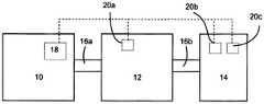
图1a是包括根据本技术的实例的增湿器的呼吸设备的示意图。该设备包括用于在正压下产生空气供给的流量发生器10、用于增加来自流量发生器的气体的湿度的增湿器12、患者接口14,例如鼻罩接口、口鼻罩接口、鼻垫接口或者鼻枕接口,三者通过空气输送管16a和16b互相连接。另选地,可以将增湿器12设置为与流量发生器10的出口直接联接,以使得不需要互相连通的输送管16a(见图1b),例如在ResMed S9TMPAP系统中。此外,如在图1c所示和以下更详细的描述中,可以将增湿器12并入互相连接的管16b内。在这种布置中,需要具有供水管12b的供水系统(或者水桶)12a以便为位于空气输送管16b内的增湿器12提供水源(液体供给)。管16a和16b可以具有例如诸如约15mm-22mm的约10mm至22mm的内径,例如大约12mm、13mm、14mm、15mm、19mm。应该注意其它直径是可以的。1a is a schematic diagram of a breathing apparatus including a humidifier according to an example of the present technology. The device includes a
流量发生器10还可以包括控制器18,其用于接收来自流量发生器的控制接口(未示出)的输入和来自一个或多个传感器20a、20b和20c的信号,以便控制流量发生器10和增湿器12的运行。传感器20a、20b和20c可以是用于检测例如环境环境、非增湿流体和增湿流体的性能的一个或者多个温度传感器、压力传感器、相对湿度传感器、绝对湿度传感器和/或流量传感器。传感器可以确定环境空气的温度。如图1a所示,可以较远地设置传感器20a、20b和20c,例如设置在增湿器12和/或患者接口14中。另选地,如图1b所示,传感器20a、20b和20c可以位于流量发生器10和/或增湿器12内。应该理解的是传感器20a、20b和20c的数量和位置可以随不同的呼吸设备的布置而变化并且传感器20a、20b和20c可以设置在流量发生器10和/或增湿器12和/或患者接口14内。还应该理解的是可以设置比图1a至1c中所示的传感器更多的传感器。The
图2a示出了根据本技术的实例的增湿器组件,其包括以虚线示出的隐藏细节。Figure 2a shows a humidifier assembly according to an example of the present technology including hidden details shown in phantom.
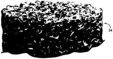
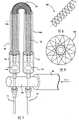
增湿器组件12包括通常的导热和电阻抗多孔材料的多孔结构24,其通过例如紧密围绕多孔结构24的管26的外壳包裹。如图所示,多孔结构24可以具有圆柱形形状;然而,也可以使用其它形状。如图2a所示,多孔结构24的一端27可以延伸超过外管26的开口端。The
连接器配件28具有诸如以套管的形式的液体(例如水)进口30以形成液体进口套管,便与从供给液体/水系统(未示出)引出的液体供给管32连接。可以使用诸如泵或通过重力供给或者其它已知的水输送装置的供给系统(未示出)和用于与在连接器配件28和外管26之间形成密封连接的密封管36连接的密封管连接套管34将水提供给供水管。连接器配件28可以包括例如Y型连接器或者T型连接器的三向连接器或者多向连接器。连接器内部的内通道允许水从进水口套管30流向套管34,然后通过密封管26并且通过多孔结构24。The
连接器配件28进一步包括密封连接器35,其用于将电导线39连接至增湿器。导线39具有从增湿器的端部延伸以连接到电源的第一端39a,和连接至外管26内部的多孔结构24的第二端39b。密封连接器35密封在共轴地通过密封管连接套管34的导线39上,继而通过与第一电连接器33的连接(例如压接连接)将导线39的第二端39b连接至位于外管26内部的多孔结构的端部31。The
多孔结构24的暴露的另一端27与诸如压接连接器的第二电连接器37连接,以便连接电源线38。电源线38连同导线39将电压施加到多孔结构两端以作为电阻加热器运行。所施加的电压可以是诸如约12V或者24V的例如从流量发生器电源取得的低压直流电。另选地,可以使用独立电源。应该理解的是,也可以使用交流电压。The exposed other end 27 of the
多孔结构24由允许水和/或水蒸气经通过其中的导热开孔材料构成。多孔材料具有开孔区域,其足够多孔以允许水流动通过该材料,诸如在不需要过多压力的情况下,从入口泵送通过或者重力供给通过到出口。在图3a和图3b中,示出了显示多孔结构24的多孔材料的实例的详细视图。The
用于多孔结构24的实例材料可以包括多孔金属材料或者多孔陶瓷材料(例如碳化硅或氮化钛),其具有适合用作用于容纳在该材料孔内的水的电阻加热器的导热性和阻抗性。诸如金属、电阻陶瓷或者泡沫碳或碳纤维的材料可能是适合的。Example materials for the
用于多孔结构的实例材料是诸如可购买于荷兰的Recemat International BV的泡沫金属。已发现镍铬铝或者

实例泡沫金属可以是通过对诸如开孔聚氨酯泡沫的泡沫聚合物进行热解和/或喷涂金属粉形成的类型。金属泡沫可以具有约90%以上的开孔体积,例如约95%,以及约0.1mm-2mm的孔径,例如约0.2mm-1mm,诸如约0.4mm。Example metal foams may be of the type formed by pyrolyzing and/or spraying metal powders on foamed polymers such as open-cell polyurethane foam. The metal foam may have an open cell volume above about 90%, such as about 95%, and a pore size of about 0.1 mm-2 mm, such as about 0.2 mm-1 mm, such as about 0.4 mm.
多孔结构24的孔隙度可以是基本上均匀的,或者可以沿柱体的长度和/或直径变化。The porosity of the
多孔结构24的电阻取决于多孔结构24的几何形状和材料类型。获得所需的增湿量(即待汽化的水的通过量)的电源要求确定所需的电压。The electrical resistance of the
图2b示出了另选实例,其中导热和电阻抗的多孔结构25包括例如碳纤维的纤维材料。纤维可优选地以拖丝结构、捻绞结构、编织结构、织带结构、毛毡结构、织物结构或带状结构的组的形式成束。纤维结构具有允许流体通过的多个孔口或孔。在图3b中,示出了显示织带纤维束25的实例的详细视图。纤维材料的实例包括碳纤维,其具有高于50%的碳含量和聚丙烯腈(PAN)、人造纤维或者树脂的前体。碳纤维直径可以小于约20微米,例如约5微米至7微米。Figure 2b shows an alternative example in which the thermally and electrically resistive
在图2a和图2b的增湿器部件中,其适于对用于呼吸设备的空气的增湿,诸如用于治疗睡眠呼吸障碍的容量为接近100L/min流量的气道正压(PAP)装置,已经发现水通过量接近0-10ml/min(例如2-5ml/min或者0-3ml/min)的增湿器适于在28℃处达到相对湿度(RH)为约80%的相对湿度。这要求高达约240W的汽化功率。另选地,在不同几何形状下,可以使用不同功率输出,例如达到约50W、达到约100W或者达到约200W的功率输出。In the humidifier component of Figures 2a and 2b, it is suitable for humidification of air used for breathing apparatus, such as positive airway pressure (PAP) with a volume of approximately 100 L/min flow for the treatment of sleep disordered breathing device, it has been found that humidifiers with a water throughput approaching 0-10ml/min (eg 2-5ml/min or 0-3ml/min) are suitable to achieve a relative humidity (RH) of about 80% relative humidity at 28°C . This requires up to about 240W of vaporization power. Alternatively, under different geometries, different power outputs can be used, eg, up to about 50W, up to about 100W, or up to about 200W of power output.
诸如约0.5-2ml/min的较小的水通过量对于许多医疗增湿的应用是足够的。Smaller water throughputs, such as about 0.5-2 ml/min, are sufficient for many medical humidification applications.
在图2a中的多孔结构的尺寸可以从直径约1mm至5mm变动,例如约2mm,从长度约20mm至200mm变动,例如约100mm。这为多孔结构提供了约10mm3至4000mm3的体积范围,例如的15mm3到500mm3,诸如314mm3。The dimensions of the porous structures in Figure 2a may vary from about 1 mm to 5 mm in diameter, eg about 2 mm, and from about 20 mm to 200 mm in length, eg about 100 mm. This provides a volume range of about 10 mm3 to 4000 mm3 for the porous structure, eg 15 mm3 to 500 mm3 , such as 314 mm3 .
围绕多孔结构24、25的外管26紧密地围绕多孔结构24、25以便容纳待经过多孔结构的水和改善多孔结构的分路作用。外管26可以由绝缘绝热、耐热震性的材料和具有较低比热容的材料形成。可以使用诸如氧化铝或者熔凝石英的陶瓷管,或者另选地,诸如热收缩管或者硅橡胶管的聚合物可应用于多孔结构24、25的外表面。在其它形式中,使用外管26不是必需的,例如多孔结构可以位于某些其它容器内。The
在操作中,在从供水系统(未示出)到连接器配件28的进水口30的压力下,可以通过例如诸如的压电泵的微型泵的供给装置(未示出)提供水的控制流量。该供给装置可以构造为将所需水量输送到进水口30。该水流流入并通过增湿器的多孔结构24、25的孔结构,同时电流也通过多孔结构24、25的电阻抗材料。从而,多孔结构24、25的材料充当用于水的电阻加热器,水与多孔结构的孔结构紧密接触,当水从进水口流向增湿器的蒸汽出27口时,对水进行加热并使其汽化。从而形成蒸汽,该蒸汽从多孔结构24的蒸汽出口27排出并输送至呼吸气体流路径。蒸汽出口27可以延伸通过周边外管26的端部并进入空气输送管以将蒸汽输送到为患者设置的呼吸气体流路径。In operation, a controlled flow of water may be provided by a supply device (not shown), such as a micropump such as a piezoelectric pump, under pressure from a water supply system (not shown) to the
在一个未示出的实例中,多孔结构24、25可以是锥形的(例如截头锥形)以便增加从进水口到蒸汽出口的直径以补偿水蒸发时蒸汽的膨胀。在这种情况下,外管26成相应的形状以符合多孔结构24、25的形状。In an example not shown, the
在利用由于高的开放区域造成的推动水通过多孔结构24、25所需的相对较低的压力,并且通过控制通过多孔结构24、25的电流来控制增湿等级的情况下,可以使用诸如外部水瓶或者可拆卸囊袋的重力供给供水装置来代替泵。可以使用蒸馏水以防止堵塞多孔结构24、25。Where the relatively low pressures required to push water through the
从而,与现有技术的水桶增湿布置相比,该增湿器布置可以提供具有低的热质量从而具有快速的控制响应的相对紧凑有效并且易于操控的增湿设备。当热滞后降低时,可以实现对湿度更快速和更精确的控制。Thus, compared to prior art bucket humidification arrangements, the humidifier arrangement may provide a relatively compact, efficient and easy to maneuver humidification device with low thermal mass and thus fast control response. When thermal hysteresis is reduced, faster and more precise control of humidity can be achieved.
在某些实例中,可以控制增湿器以使得水蒸气的含量取决于或者成比例于用于患者的空气流量。另外或者另选地,可以仅在部分呼吸周期期间(例如在同步于患者的吸气的脉冲周期中)产生蒸汽以使通过在呼气期间不进行增湿的方式来降低对水和电功率的需求。继而,这可以导致使用较小的供水系统或者水桶,以及使用改良的电功率效率和/或用于装置的电池使用期限。In some instances, the humidifier can be controlled such that the water vapor content depends on or is proportional to the air flow for the patient. Additionally or alternatively, steam may be generated only during part of the breathing cycle (eg, during a pulse cycle synchronized with the patient's inhalation) so that water and electrical power requirements are reduced by not humidifying during exhalation . This, in turn, can lead to the use of a smaller water supply system or bucket, as well as the use of improved electrical power efficiency and/or battery life for the device.
图7示出了本技术的另选实例。如图所示,增湿器组件50包括导热和电阻抗多孔材料的普通多孔结构52。除了在此实例中,多孔结构封装在具有两部分54a和54b的外壳中(或可选地,两个单独的壳体54a和54b),增湿器50的布置通常类似于图2a和图2b所示的实例。多孔结构52的一部分作为增湿器50的蒸汽出口56,在壳体54a和54b的开口端处暴露。在另一端,连接器配件58接收来自液体供给管60的液体(例如水),并且经由密封管连接套管64将该液体提供到密封管62。可以使用泵或者通过重力供给或其它已知的液体运输装置提供液体。FIG. 7 shows an alternative example of the present technique. As shown, the humidifier assembly 50 includes a generally
暴露的蒸汽出口端56可以是插入到空气流管(未示出)的增湿器组件50的唯一部分。可在例如与气流管的纵轴平形、垂直或者以在两者之间的任何角度的不同角度下将蒸汽出口56插入并暴露于空气流。对于这种增湿器组件设置50,所有供水系统和电连接端一起位于一端,并且蒸汽出口56位于相对端。这提供了更加紧凑的设计并且可以提高装配与拆卸的易操作性。例如,可以在密封管62处拆卸增湿器组件50,并且可以断开液体供给管60以隔绝加热元件部分80。加热元件部分80可以是消耗性物品,并且可以在多次使用后进行处理和替换。另选地,可以在电连接端70,将加热元件部分80从增湿器上拆卸,并且将加热元件部分作为消耗性物品处理和替换。The exposed
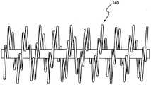
空气加热器线圈air heater coil
图4示出一个实例,其中通常与上述图2a和2b示出的增湿器类似的增湿器112支撑在诸如PAP装置的呼吸设备的空气输送管116内或者在部分空气输送管116内。以“1”开始的附图标记表示与如图2a和图2b中的特征类似的特征(例如附图标记128指示连接器配件)。Figure 4 shows an example in which a
当在空气路径中加热空气时,理想的是提供具有小体积的空气加热器。可以提供较小的CPAP装置,降低成本并减少功耗(例如用于便携式装置的较长的电池使用期限)。在呼吸系统内,空气加热器可以与增湿器一起使用或者不与增湿器一起使用。When heating air in the air path, it is desirable to provide an air heater with a small volume. Smaller CPAP devices can be provided, reducing cost and power consumption (eg, longer battery life for portable devices). Within the respiratory system, air heaters may or may not be used with humidifiers.
对于给定的空气导管,其横截面(例如通常是圆形)沿纵向长度可能是相同的,因此其长度可确定容积。为了有效地加热空气,各空气流的流动应该接触(或者非常接近于)热导线以便有效的热传递。如果流动是层流,则对于空气路径的总横截面来说,可能理想的是其由加热线的轴向投影“覆盖”并且没有(或很少)重叠的导线投影。For a given air duct, its cross-section (eg, typically circular) may be the same along its longitudinal length, so its length determines the volume. In order to heat the air efficiently, the flow of each air stream should contact (or be very close to) the heat wires for efficient heat transfer. If the flow is laminar, it may be desirable for the total cross-section of the air path to be "covered" by the axial projection of the heating wires and with no (or little) overlapping wire projections.
可以通过在张力下使导线卷绕心轴,而在该心轴上形成梳麻机式加热器线圈。如果心轴具有圆形截面,那么形成的形式可以是如图8所示的螺旋弹簧。Comb heater coils can be formed on a mandrel by winding the wire under tension around a mandrel. If the mandrel has a circular cross-section, it can be formed in the form of a coil spring as shown in FIG. 8 .
如果心轴具有高的长宽比的矩形横截面,那么形成的形式是如图9所示的一系列星形弯曲线。梳麻机式线圈卷绕在心轴周围,并且卷绕完成时,允许线圈弹离心轴以呈现在外圆周上具有点或者拐角的错列的“星”形元件的线圈的形状。然而,这可以沿不会发生空气加热的线圈中心形成大的开放空间。在梳麻机式线圈中的热导线的长度集中围绕于中心孔区域并且仅仅是拐角或者点在外径上(当从端视图看时)。If the mandrel has a rectangular cross-section with a high aspect ratio, the resulting form is a series of star-shaped curved lines as shown in FIG. 9 . The comb coil is wound around the mandrel, and when the winding is complete, the coil is allowed to bounce off the shaft to assume the shape of the coil with staggered "star" shaped elements with points or corners on the outer circumference. However, this can create a large open space along the center of the coil where air heating does not occur. The length of the hot wire in the comb coil is concentrated around the central hole area and only the corners or points are on the outer diameter (when seen from the end view).
这些形状中的每个都在中心具有核心,其不加热流经中心核心的空气流。为了均匀地加热空气流,需要从外部热空气向较冷的中心空气流的热扩散。另选地,可以引入紊流将气流混合以获得均匀的空气温度。然而,引入的紊流可以增加空气流的阻抗并增加系统所需的功率。Each of these shapes has a core in the center that does not heat the air flow through the central core. To uniformly heat the air flow, heat diffusion from the outer hot air to the cooler central air flow is required. Alternatively, turbulence can be introduced to mix the airflow to achieve a uniform air temperature. However, the turbulence introduced can increase the impedance of the air flow and increase the power required by the system.
梳麻机式线圈的另一个问题是突出的导线可以集中在相当狭窄的环形带中(当卷绕时取决于导线张力和心轴形状),并且流经这个狭窄的环形带的空气流通常能够接收绝大部分热量。这可以造成不均匀的空气加热并且可以进一步导致无效率。Another problem with comb-type coils is that the protruding wire can be concentrated in a fairly narrow annular band (depending on the wire tension and mandrel shape when wound), and the air flow through this narrow annular band can often receive most of the heat. This can cause uneven air heating and can further lead to inefficiencies.
导线弯折机可以用于将导线弯曲成实现覆盖空气管的整体或者大体全部或者大部分横截面的加热区域的结构,以便在较短的长度中完成空气加热。可以形成线圈以便当它们接近中心核心时导线的环圈(如在梳麻机式心轴形成线圈中的围绕中心开口核心区域)替代地弯曲。因此,若干线圈环圈的组合可以形成中心核心的周边。这允许中心核心的尺寸变化,或者可以形成为使得中心核心完全闭合,也就是说,用热导线有效地填充完整的或者基本上全部的或者大部分横截面。A wire bender can be used to bend the wire into a configuration that achieves a heating area covering the entire or substantially all or most of the cross-section of the air duct to accomplish air heating in shorter lengths. Coils can be formed so that loops of wire (such as in the core area around a central opening in a burr forming coil) instead bend as they approach the central core. Thus, the combination of several coil loops can form the perimeter of the central core. This allows the size of the central core to vary, or can be formed such that the central core is completely closed, that is, effectively filling a complete or substantially all or most of the cross-section with thermal wires.
通过选择每个线圈环圈大约转360°的角度而不是360的因子,随后的线圈与第一“排”不对直。通过在空气蒸汽中呈现更多的热导线,这允许对横截面区域的不同部分覆盖。可以使用外弯曲部和内侧弯曲部的曲率半径确定中心核心开放腔体的尺寸。例如,通过外半径、外半径的外长度、内半径和内半径的内长度以及线圈的间距确定线圈的形状。这些尺寸也可确定内部中心开放核心空间直径和整个线圈结构的外径。By choosing to turn each coil loop approximately 360° instead of a factor of 360, subsequent coils are not aligned with the first "row". This allows coverage of different parts of the cross-sectional area by presenting more thermal conductors in the air vapor. The radii of curvature of the outer and inner curvatures can be used to determine the size of the central core open cavity. For example, the shape of the coil is determined by the outer radius, the outer length of the outer radius, the inner radius and the inner length of the inner radius, and the spacing of the coils. These dimensions also determine the inner center open core space diameter and the outer diameter of the overall coil structure.
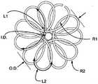
在图6d中,示出了线圈尺寸的实例。线圈可以具有约20mm至30mm的外径O.D.,例如约25.4mm。线圈可以具有约1mm至5mm的内径I.D.,例如约3.0mm。线圈环可以具有约15mm至25mm的第一长度(例如约19.3mm)和约5mm至12mm的第二长度(例如约8.85mm)。第一长度L1可以使由具有约15mm至20mm的半径R1(例如约17.4mm)的导线弯曲的方式形成,并且第二长度L2可以使由具有约1mm至5mm的半径R2(例如约3mm)的导线弯曲的方式形成。In Figure 6d, examples of coil dimensions are shown. The coil may have an outer diameter O.D. of about 20mm to 30mm, eg about 25.4mm. The coil may have an inner diameter I.D. of about 1 mm to 5 mm, for example about 3.0 mm. The coil loop may have a first length of about 15mm to 25mm (eg, about 19.3mm) and a second length of about 5mm to 12mm (eg, about 8.85mm). The first length L1 may be formed by bending a wire having a radius R1 of about 15 mm to 20 mm (for example, about 17.4 mm), and the second length L2 may be formed by a wire having a radius R2 of about 1 mm to 5 mm (for example, about 3 mm). The way the wire is bent is formed.
通过线圈结构辐射的热量可以通过线圈结构的电阻率、线圈结构的纵向长度和线圈结构的横截面直径确定。The heat radiated through the coil structure can be determined by the resistivity of the coil structure, the longitudinal length of the coil structure, and the cross-sectional diameter of the coil structure.
在另选实例中,在线圈结构内,线圈半径可以改变,以使得部分环圈F是扁平的并且远离线圈结构的中心轴。如图6e所示,这种设置可以为空气流提供更加均匀一致的覆盖。In an alternative example, within the coil structure, the coil radius may vary such that the partial loop F is flat and away from the central axis of the coil structure. As shown in Figure 6e, this arrangement can provide a more uniform coverage of the air flow.
在图4中示意性地示出的增湿器112通过一个或多个安装结构140支撑在空气输送管116内,以使得增湿器的主轴通常平行于管116的轴以便对管内的空气流呈现最小的干扰。也就是说,增湿器基本上平行于空气输送管的纵向轴安装。另选地,增湿器能够以不沿纵向轴的不同的构造安装,但是在蒸汽出口内暴露于空气流。The
如图5和图6所示,安装结构可以包括诸如“螺旋线圈”或“梳麻机式线圈”的布置(例如图8和图9中所示)或者由导线形成的“莲座状线圈”的设置的线圈结构以产生与空气输送导管116的内表面接合并与增湿器112的外表面接合的结构,以便在管内大体共轴地支撑增湿器。可以利用导线弯曲机形成“莲座状线圈”结构。在这种布置中,安装结构还能够可选择地用作电阻加热器,以便在从增湿器接收水蒸气前加热在空气输送管116内流动的空气,以使气体流对蒸汽的占有率增加。As shown in Figures 5 and 6, the mounting structure may include arrangements such as "spiral coils" or "comber coils" (eg, as shown in Figures 8 and 9) or "rosette coils" formed of wire The coil structure is arranged to create a structure that engages the inner surface of the
参照图4至图6e,示出了“莲座状”加热线圈形式的安装结构140。在莲座状加热线圈中,导线不是卷绕在心轴周围形成而是利用两个不同的半径在导线弯曲工具上形成。莲座状线圈的形式允许热导线的成比例变大的长度位于线圈的周边以加热流入该区域的更大体积的空气。这种形式还允许较小的孔位于线圈中心的下方(并可调整尺寸)并且可以用于支撑围住蒸汽的元件的外管26。Referring to Figures 4 to 6e, a mounting
设计莲座状的“花瓣”或环圈以使得在各个截面或“花”上都存在多个“花瓣”或环圈,并且下一个花具有补偿在先的花瓣或者与在先的花重叠的花瓣,因此确保沿管的空气路径在空气流动的某一阶段紧密地靠近热导线的任何部分。可以选择适当的补偿以便完全覆盖外管126和空气输送导管116之间的环形区域。该设计制作出比现有设计的加热线圈更加紧凑的空气加热线圈。Designing rosette-like "petals" or loops such that there are multiple "petals" or loops on each section or "flower" and the next flower has petals that compensate for or overlap with the previous flower , thus ensuring that the air path along the tube is in close proximity to any part of the thermal wire at some stage of the air flow. Appropriate compensation may be selected to fully cover the annular area between the
增湿和用水管理Humidification and water management
控制器18(如图1所示)可以接收来自至少一个传感器20a、20b和20c的信号,并且构造成控制增湿器在预设温度和预设相对湿度提供可呼吸气体的增湿流。进一步地,控制器18可以构造成控制功率供给以便在患者呼吸周期的部分阶段期间内输送蒸汽,例如仅在患者吸气阶段期间内。通过这样做,可以根据需要管理耗水量,并且将水进行保存以减少浪费。The controller 18 (shown in FIG. 1 ) may receive signals from at least one of the
从已知的周围环境状态,可以对增湿器的操作可以布置为使得能够获得在患者接口端处的理想状态。例如,首先测量环境温度和相对湿度(或者测量位于增湿器前面的任何相同点的温度和相对湿度,例如流量发生器内)。利用这些测量值,通过下面的公式计算绝对湿度。From the known ambient conditions, the operation of the humidifier can be arranged such that the ideal conditions at the patient interface end can be obtained. For example, first measure the ambient temperature and relative humidity (or measure the temperature and relative humidity at any same point in front of the humidifier, such as within a flow generator). Using these measurements, the absolute humidity is calculated by the formula below.

其中:in:
A,m,Tn=常量见表1A, m, Tn = constants see Table 1
T=温度(℃)T = temperature (°C)

表1Table 1
然后从%RH计算水蒸气压力:Then calculate the water vapor pressure from %RH:
计算PW=PWS*RH/100(hPa)Calculate PW =PWS *RH/100(hPa)
实例:Example:
环境温度是40℃,并且RH是50%。计算Td:The ambient temperature was 40°C and the RH was 50%. Calculate Td :
PW=PWS(40℃)*50/100=36.88hPaPW =PWS (40℃)*50/100=36.88hPa
实例为30℃和80%RH,(目标点)Example is 30°C and 80% RH, (target point)
PWS=6.1162x 10*(7.5892x30/(30+240.71))PWS = 6.1162x 10*(7.5892x30/(30+240.71))
PWS=42.415hPaPWS =42.415hPa
和and
PW=PWS x RH/100PW =PWS x RH/100
Pw=33.932hPaPw =33.932hPa
将绝对湿度定义为一定体积下水蒸汽的质量。如果假设理想的气体运行状况,则能够利用(17)计算绝对湿度:Define absolute humidity as the mass of water vapor in a given volume. If ideal gas operating conditions are assumed, absolute humidity can be calculated using (17):
A=C*PW/T(g/m3),(17)A=C*PW /T (g/m3 ), (17)
其中:in:
C=常量2.16679gK/JC=constant 2.16679gK/J
PW=蒸汽压力,单位PaPW = steam pressure, in Pa
T=温度,单位KT = temperature, unit K
实例:Example:
环境温度是20℃并且相对湿度是80%。计算绝对湿度:The ambient temperature was 20°C and the relative humidity was 80%. Calculate absolute humidity:
PW=PWS(20℃)*80/100=18.7hPaPW =PWS (20℃)*80/100=18.7hPa
A=2.16679*1870/(273.16+20)=13.82g/m3A=2.16679*1870/(273.16+20)=13.82g/m3
实例为30℃和80%RH,(目标点)Example is 30°C and 80% RH, (target point)
PW=33.932hPa(从上面)PW = 33.932hPa (from above)
和and
AH=2.16679x 3393.2/(273.16+30)AH=2.16679x 3393.2/(273.16+30)
AH=24.252g/m3(或mg/L)AH=24.252g/m3 (or mg/L)
因此目标AH是24.252mg/LSo the target AH is 24.252mg/L
对于给定的流量F(单位L/min),待注入空气流的水量是:For a given flow F (in L/min), the amount of water to be injected into the air stream is:
Q=(24.252–环境AH)x F mg/minQ=(24.252 – ambient AH) x F mg/min
接近室温的水,1mg~1mlNear room temperature water, 1mg~1ml
理想的患者状况可以是约24.5mg/L(水/空气的升数)的绝对湿度。从24.5mg/L减去所测量的绝对湿度并且这是按照mg/L需要增加的水量。计算空气流并且通过所需增加的水量(按照mg/L)乘以空气流(按照L/min),并且结果是所需的水泵送速率(以mg/min)。该水量可以通过由电压和/或频率控制的压力泵泵送。The ideal patient condition may be an absolute humidity of about 24.5 mg/L (liters of water/air). Subtract the measured absolute humidity from 24.5 mg/L and this is the amount of water needed to increase in mg/L. Calculate the air flow and multiply the air flow (in L/min) by the required increase in water (in mg/L) and the result is the required water pumping rate (in mg/min). This amount of water can be pumped by a pressure pump controlled by voltage and/or frequency.
从水流流量,通过参考以经验推得的图12,可以确定所需的功率。From the water flow rate, the required power can be determined by referring to Figure 12, which is derived empirically.
操作模式operating mode
增湿器控制Humidifier Control
图10示出了增湿器运行模式的实例的流程图。处理步骤1002示出了对加热管300的控制。加热管可以是类似于在例如U.S.2008/0105257 A1和/或U.S.2011/0023874 A1中所描述的加热管,两者的全部内容通过引用并入此处。流程开始于S1,并且包括接收输送到患者接口的所感测到的气体温度的测量值。可以从传感器20b提供所感测到的气体温度。在S2提供待输送到患者接口的气体的预设温度Tm。预设温度Tm可以从例如通过使用者(即临床医生)或者患者从例如如图1a至1c所示的设备的输入中选取。预定温度还可以设置为如在例如U.S.2009/0223514 A1和/或U.S.2011/0023874 A1中所公开的。传感器20b测量所感测到的气体温度并且与在S2提供的所需的(即预定的)目标温度相比较。在S6,确定差值ΔTm,并且将其反馈回加热管控制器18以控制加热管的操作300。此处理可以类似于U.S.2009/0223514 A1所公布的内容,其全部内容通过引用并入此处。Figure 10 shows a flow diagram of an example of a humidifier mode of operation.
处理步骤1004在所需的目标温度处,确定所需的水流流量以输送期望的或者预定的目标湿度。如前面的实例计算中所述,可以通过测量环境空气温度和环境相对湿度计算环境绝对湿度。该环境绝对湿度与目标所需的绝对湿度(利用目标(即理想的或预设的)温度和相对湿度所计算的)相比较以计算所需的水量。对于所感测到的气体流,并了解每单位体积的气体所需要输送的水量,可以计算水流流量。如图10所示,在S2,提供预设的所输送的气体温度Tm,并且在S4处提供待输送给患者接口的预设的相对湿度RHm。以类似于例如U.S.2009/0223514 A1和/或U.S.2011/0023874 A1中所述的方式,可以例如通过使用者或患者选取预设的相对湿度RHm。在S8处,将RHm和Tm的预设值提供给湿度计算,并且在S12,提供待输送给患者接口的预设的绝对湿度AHm。
通过输入环境温度Ta(例如通过传感器20a确定)和输入在S10处进入湿度计算的环境相对湿度RHa(例如通过传感器20d确定),并且通过在S14处提供环境绝对湿度AHa,确定环境绝对湿度。在S16处,确定预设绝对湿度AHm和环境绝对湿度Aha之间的差值ΔΑΗ。The ambient absolute humidity is determined by inputting the ambient temperature Ta (eg determined by the
处理步骤1006示出了对输入到用泵泵送水和对加热元件进行加热两方面的功率的控制。利用所计算的水流流量,并且了解足以抽取水、加热水和汽化水所需的预设能量,能够确定用于控制蒸汽喷射器的流程所需的电压、频率和功率等。在S22中,在预设温度下,使用所感测的气体流F(例如通过传感器20c所确定)和差值ΔΑΗ来计算所需的水流流量以输送预定湿度。另选地,基于如US 2010/0319697中所述的电机电流,可以估算流量。在S24,确定或者提供预设电压和频率以抽取任何预设水流流量,并且在S26,确定所需的电压和频率以抽取所需的水流流量。使用在S20汽化任何液体流量的预设功率,连同所需的泵电压和频率,以在S28确定汽化泵送的液体流量所需的功率。将在S28确定的所需的功率提供给增湿器,例如提供给增湿器控制器18。
处理步骤1008示出了对空气加热线圈的控制140。通过利用例如传感器20e感测增湿器出口处的温度,并通过与所需的目标空气流温度Tm相比较,在S18,能够确定通过传感器20e提供的感测温度和预设温度Tm之间的差值ΔT。能够将差值ΔT提供给空气加热器控制器18以提供对空气加热器的反馈控制140。
应该理解的是,可以提供控制器18以控制液体运输(即泵)、空气加热器(即线圈140)、加热管300和增湿器(即增湿器112)。还应该注意,控制器18可以是多个控制器,并且可以在不同部件中提供多个控制器。例如,可以在流量发生器、增湿器、泵和加热管等中提供控制器。还应该,控制器或者所有控制器可以是以例如微控制器、特殊程序的通用计算机或者ASIC的形式。应该进一步理解的是,从控制器中所提供的储存于存储器中的软件程序、其它可执行代码或者指令中,执行如图10所示的流程。甚至更进一步理解的是,控制器的存储器可以包括例如以经验性确定的系数和/或用于流程的各种心理测量计算以及其它计算的查阅表。It should be understood that the
图11示出了增湿器的操作的另一个实例模式的流程图。图11包括如图10所示的所有流程步骤,并进一步包括用于控制加热元件的运行的控制步骤1010。如1010中所示,通过在S30预设所需的目标加热元件的出口温度,可以控制加热元件的操作。例如,该预设温度可以是要求用于完全汽化流经加热元件的液体的最低温度。通过用例如传感器20f监控在加热元件出口的感测温度,能够控制加热元件以确保通过确定S32处的差值ΔΤ并通过利用反馈控制环路来维持最低温度。应该注意,在一些现有技术的形式中,可以不需要如图10或图11所示的所有步骤。在一些情况中,可以包括另选步骤,并且可以省略其它步骤。11 shows a flow diagram of another example mode of operation of the humidifier. Figure 11 includes all of the flow steps shown in Figure 10 and further includes a
平衡电路测试Balanced Circuit Test
可以使用平衡电路测试以检测空气加热器和/或加热元件是否有故障。除了设置在加热元件两端的两个电连接点以外,通过提供与加热元件的中心的连接,可以激活平衡电路测试。测量从中心分接头到各个端电连接点的电压、电流或电阻等,每个部分的结果应该与其它部分的结果相同(平衡)。如果测量值不匹配,则表明电路故障。A balanced circuit test can be used to detect faulty air heaters and/or heating elements. By providing a connection to the center of the heating element in addition to the two electrical connection points provided at both ends of the heating element, the balanced circuit test can be activated. Measure the voltage, current or resistance, etc. from the center tap to the electrical connection points of the various terminals, the results of each section should be the same (balanced) as the results of the other sections. If the measurements do not match, the circuit is faulty.
温度合理性模式Temperature Rationality Mode
当加热元件和/或空气加热器未打开时,通过比较在不同传感器处的感测温度,使得系统能够检测传感器中的故障,即在当传感器应该提供相同的结果时的情况下,其未提供与其它传感器相同的结果。By comparing the sensed temperatures at different sensors when the heating element and/or air heater is not on, enables the system to detect faults in the sensor, i.e. in the case where the sensor is not providing the same result when it should be providing the same result Same result with other sensors.
供水系统和加热器的构造Construction of water supply system and heater
液体供给系统可以是水瓶,其与泵进口连接以使得将水供给给泵并且将水泵送到加热元件的进口。该瓶可以是刚性的或者可拆卸的。在加热元件的进口,水转换成蒸汽,并且将所生成的蒸汽注入增压的空气流。为了改进泵的运行,可以给供水系统增压。这可以平衡系统,因此该泵不会对在加热元件出口处所经历的压力造成不利。一种实例构造是装配具有直到瓶顶部的开口的刚性液体容器,其连接至增加的空气流。另选地,可以在被增压的刚性外壳内提供可压缩的容器。也可以允许用变化的压力给容器轻微地充气/放气。这种配置可以允许使用用于水的无头泵(zero-head bump)。The liquid supply system may be a water bottle connected to the pump inlet such that water is supplied to the pump and pumped to the inlet of the heating element. The bottle can be rigid or removable. At the inlet of the heating element, the water is converted to steam, and the resulting steam is injected into the pressurized air flow. To improve pump operation, the water system can be pressurized. This balances the system so the pump is not detrimental to the pressure experienced at the outlet of the heating element. An example configuration is to assemble a rigid liquid container with an opening up to the top of the bottle, which is connected to increased air flow. Alternatively, the compressible container may be provided within a pressurized rigid housing. It is also possible to allow the container to be slightly inflated/deflated with varying pressures. This configuration may allow the use of a zero-head bump for the water.
在另一个另选物中,患者的呼气可以被引导以将泵送的水致动到加热元件中。。例如,当发生患者的吸气周期时,利用压力抑制机制和控制,可以施加来自患者的呼气压力以泵送水供给。这可以协助泵或代替泵所执行的功能。In another alternative, the patient's exhalation may be directed to actuate the pumped water into the heating element. . For example, with the pressure suppression mechanism and control, expiratory pressure from the patient can be applied to pump the water supply when the patient's inspiratory cycle occurs. This can assist or replace the functions performed by the pump.
可以提供多个增湿器系统构造以实施本技术。例如,供水系统可以位于流量发生器/增湿器系统的附近或者内部;或者在系统之外并经由导管连接至增湿器。泵可以靠近流量发生器/增湿器系统提供或提供在流量发生器/增湿器系统内部;或者通过供水系统提供在如上所述的系统外部;或者可以靠近患者接口(面罩)提供并经由导管将其连接至供水系统和加热元件。空气加热器可以靠近流量发生器/增湿器系统提供或者提供在流量发生器/增湿器系统内部;靠近空气流管提供或者提供在其内部,在靠近流量发生器/增湿器系统的位置;提供在沿空气流管的长度的位置;或者靠近患者接口提供。将加热元件位于空气加热器下游是优选的,以使空气加热器加热空气流可以有助于维持空气流的保水性并维持相对湿度。Multiple humidifier system configurations may be provided to implement the present technology. For example, the water supply system may be located near or within the flow generator/humidifier system; or external to the system and connected to the humidifier via a conduit. The pump can be provided close to or inside the flow generator/humidifier system; or external to the system as described above through a water supply; or can be provided close to the patient interface (mask) and via a conduit Connect it to the water supply and heating element. Air heaters may be provided close to the flow generator/humidifier system or within the flow generator/humidifier system; close to or within the air flow duct, near the flow generator/humidifier system ; provided at a location along the length of the air flow tube; or close to the patient interface. Positioning the heating element downstream of the air heater is preferred so that heating the air flow by the air heater can help maintain the water retention of the air flow and maintain relative humidity.
传感器sensor
可以将温度传感器加到增湿器的进口端和出口端以检测故障状态,例如用于防止加热元件过热(例如因缺乏水)。通过传感器所检测的情况可以指示故障状态。Temperature sensors may be added to the inlet and outlet ends of the humidifier to detect fault conditions, eg to prevent overheating of the heating element (eg due to lack of water). A condition detected by the sensor may indicate a fault condition.
例如,如果出口传感器检测到小于100℃的温度,则这可能表明蒸汽尚未形成并且水将代替蒸汽出来。这种情况可以是加热元件故障、错误的水流流量和/或错误的功率等级的结果。如果出口传感器检测到显著地高于100℃的温度,则这可能表明水可能已经停止流动。这可能是泵故障和/或泵堵塞的结果。For example, if the outlet sensor detects a temperature of less than 100°C, this may indicate that steam has not yet formed and water will come out in place of the steam. This condition can be the result of a heating element failure, wrong water flow rate, and/or wrong power level. If the outlet sensor detects a temperature significantly above 100°C, this may indicate that the water may have stopped flowing. This may be the result of pump failure and/or pump blockage.
如果进口传感器检测到接近室温的温度并且施加了功率,则可能是表明水在流动(即加热元件不是在干烧)。如果进口传感器检测到显著高于室温的温度,则可能表明水未流动,或者施加了太大的功率。If the inlet sensor detects a temperature near room temperature and power is applied, it may be an indication that water is flowing (ie, the heating element is not drying out). If the inlet sensor detects a temperature significantly higher than room temperature, it may indicate that the water is not flowing, or that too much power is being applied.
在正常运行期间,传感器通常具有预期的运行范围,因此与所预期的运行状态的任何偏离可以表明传感器故障。传感器还可以用于控制加热元件的功率来代替使用诸如图1的经验性图表。During normal operation, sensors typically have an expected operating range, so any deviation from the expected operating state can indicate sensor failure. Sensors can also be used to control the power of the heating element instead of using an empirical graph such as FIG. 1 .
空气温度传感器可以位于空气加热器和蒸汽喷射出口位置的下游。该传感器可以检测实时空气温度并在封闭环圈反馈中控制施加到空气加热器线圈结构的功率。因此,可以将增湿的空气温度控制并调节至所需的状态,例如30C。An air temperature sensor may be located downstream of the location of the air heater and steam jet outlet. The sensor can detect real-time air temperature and control the power applied to the air heater coil structure in closed loop feedback. Therefore, the humidified air temperature can be controlled and adjusted to a desired state, such as 30C.
灭菌&清洗模式Sterilization & Cleaning Mode
增湿器可以使用干热灭菌法破坏微生物。也就是说,在不存在水蒸汽的情况下将增湿器加热一段时间,以使得通过加热过程破坏微生物。当患者不使用该装置时,在例如白天期间,启动用于CPAP增湿器的干热灭菌。可选地,干热灭菌可以在患者治疗期间之前和/或之后运行。Humidifiers can destroy microorganisms using dry heat sterilization. That is, the humidifier is heated in the absence of water vapor for a period of time so that microorganisms are destroyed by the heating process. Dry heat sterilization for the CPAP humidifier is initiated when the patient is not using the device, eg, during the day. Optionally, dry heat sterilization can be run before and/or after the patient treatment period.
对干热灭菌有效的一些实例加热温度-时间过程是:Some examples of heat-temperature-time courses that are effective for dry heat sterilization are:
·160-170摄氏度加热120分钟;· Heating at 160-170 degrees Celsius for 120 minutes;
·170-180摄氏度加热60分钟;以及· Heating at 170-180 degrees Celsius for 60 minutes; and
·180-190摄氏度加热30分钟。· Heating at 180-190 degrees Celsius for 30 minutes.
以较高的温度加热较短时间期间,或者以较低的温度加热较长的时间期间也可以是有效。Heating at a higher temperature for a shorter period of time, or heating at a lower temperature for a longer period of time may also be effective.
如上所述,增湿器可以具有位于加热元件的进口端和出口端的温度传感器。可以将通过传感器检测的温度等级输入到封闭回路反馈系统中,以控制加热元件在选定的时间段内加热到所需的温度等级。另选地,或者结合加热元件,还可以加热空气加热器线圈以用于干热灭菌过程。As mentioned above, the humidifier may have temperature sensors at the inlet and outlet ends of the heating element. The temperature level detected by the sensor can be input into a closed loop feedback system to control the heating element to heat to the desired temperature level for a selected time period. Alternatively, or in conjunction with heating elements, the air heater coils may also be heated for use in dry heat sterilization processes.
增湿器可以具有湿加热/非加热清洗功能模式以用于去除来自加热元件的残留物、沉积物或者微生物。增湿器可以构造为允许液体流经加热元件(具有或不具有对加热元件电阻加热的激活)以冲出不需要的微粒或有机物。可以在例如患者治疗期间之前和/或之后启动清洗模式。可以通过改变液体流量的控制参数和加热温度设定清洗模式,并且清洗模式可以连续不断地或者在变化的频率周期中运行。利用定时器,可以监控和/或控制清洗模式的启动/失效的计时。The humidifier may have a moist heating/non-heating cleaning function mode for removing residues, deposits or microorganisms from the heating element. The humidifier can be configured to allow liquid to flow through the heating element (with or without activation of resistive heating of the heating element) to flush out unwanted particles or organics. The wash mode may be initiated, eg, before and/or after a patient treatment session. The cleaning mode can be set by changing the control parameters of the liquid flow and the heating temperature, and the cleaning mode can be operated continuously or in varying frequency cycles. Using the timer, the timing of activation/deactivation of the cleaning mode can be monitored and/or controlled.
本技术的某些方面的一个优点是提供较小的和/或紧凑的增湿器。例如,可以减少水的体积。本技术的某些结构的另一方面是这些结构可能成本更低,例如水在单独的系统中并且未增压,此外在桶内不需要一定的压力密封。在某些结构中,由于存在较少的水,则可能需要更少的倒溢保护。One advantage of certain aspects of the present technology is to provide a smaller and/or compact humidifier. For example, the volume of water can be reduced. Another aspect of certain structures of the present technology is that these structures may be less costly, eg the water is in a separate system and not pressurized, and furthermore does not require some pressure sealing within the tub. In some structures, less spill protection may be required due to the presence of less water.
本技术的某些方面的优点是可以提供一种增湿器,其能够更迅速地响应变化的环境的,例如以呼吸为基础的一次呼吸,或者导致更快速的启动。本技术的某些方面的优点是对所提供的增湿量提供更精确的控制。An advantage of certain aspects of the present technology is that a humidifier can be provided that is more responsive to changing circumstances, such as a breath-based breath, or that results in a more rapid activation. An advantage of certain aspects of the present technology is to provide more precise control over the amount of humidification provided.
通过使用更高效的加热元件,本技术的某些方面的另一个优点是更高效的能源利用。本技术的某些方面的另一优点是能够制造更广范围的不同的形状和/或构造,例如加热元件能够以各种的不同的形状和/或构造设置。在一种形式中,加热元件可以提供在增湿管内。Another advantage of certain aspects of the present technology is more efficient energy utilization through the use of more efficient heating elements. Another advantage of certain aspects of the present technology is the ability to manufacture a wider range of different shapes and/or configurations, eg, heating elements can be provided in a variety of different shapes and/or configurations. In one form, the heating element may be provided within the humidification tube.
尽管描述了本技术的特定的实施方式,但在不背离本发明的本质特征的情况下,对于本领域的技术人员来说,显而易见的是本发明能够以其它具体形式体现。因此,本实施例和本实例在所有方面被认为是说明性的而非限制性的,本发明的范围通过所附的权利要求而非前面的描述表明,因此在权利要求等价物的意义和范围之内的所有变化包含在此范围内。应该进一步理解,除非出现相反指示,否则在此对于已知的现有技术的任何引用不构成承认此现有技术是本发明所涉及领域的这些技术人员公知。While particular embodiments of the present technology have been described, it will be apparent to those skilled in the art that the present invention can be embodied in other specific forms without departing from essential characteristics of the invention. Accordingly, this embodiment and this example are to be considered in all respects to be illustrative and not restrictive, the scope of the invention being indicated by the appended claims rather than the foregoing description, and therefore within the meaning and scope of equivalents of the claims. All changes within are included in this range. It should be further understood that, unless indicated to the contrary, any reference herein to known prior art shall not constitute an admission that such prior art is well known to those skilled in the art to which the invention relates.
Claims (21)
Applications Claiming Priority (6)
| Application Number | Priority Date | Filing Date | Title |
|---|---|---|---|
| AU2011900214AAU2011900214A0 (en) | 2011-01-24 | Humidifier | |
| AU2011900214 | 2011-01-24 | ||
| AU2011901960AAU2011901960A0 (en) | 2011-05-20 | Humidifier | |
| AU2011901960 | 2011-05-20 | ||
| PCT/AU2012/000056WO2012100291A1 (en) | 2011-01-24 | 2012-01-24 | Humidifier |
| CN201280006394.0ACN103328031B (en) | 2011-01-24 | 2012-01-24 | Humidifier |
Related Parent Applications (1)
| Application Number | Title | Priority Date | Filing Date |
|---|---|---|---|
| CN201280006394.0ADivisionCN103328031B (en) | 2011-01-24 | 2012-01-24 | Humidifier |
Publications (1)
| Publication Number | Publication Date |
|---|---|
| CN114522318Atrue CN114522318A (en) | 2022-05-24 |
Family
ID=46580117
Family Applications (4)
| Application Number | Title | Priority Date | Filing Date |
|---|---|---|---|
| CN201280006394.0AActiveCN103328031B (en) | 2011-01-24 | 2012-01-24 | Humidifier |
| CN202210122151.9APendingCN114522318A (en) | 2011-01-24 | 2012-01-24 | Humidifier |
| CN201910380473.1AActiveCN110269990B (en) | 2011-01-24 | 2012-01-24 | Humidifier |
| CN201710087480.3AActiveCN107029334B (en) | 2011-01-24 | 2012-01-24 | Humidifier |
Family Applications Before (1)
| Application Number | Title | Priority Date | Filing Date |
|---|---|---|---|
| CN201280006394.0AActiveCN103328031B (en) | 2011-01-24 | 2012-01-24 | Humidifier |
Family Applications After (2)
| Application Number | Title | Priority Date | Filing Date |
|---|---|---|---|
| CN201910380473.1AActiveCN110269990B (en) | 2011-01-24 | 2012-01-24 | Humidifier |
| CN201710087480.3AActiveCN107029334B (en) | 2011-01-24 | 2012-01-24 | Humidifier |
Country Status (6)
| Country | Link |
|---|---|
| US (3) | US10307559B2 (en) |
| EP (2) | EP2667919B1 (en) |
| JP (4) | JP2014506486A (en) |
| CN (4) | CN103328031B (en) |
| AU (1) | AU2012211031B2 (en) |
| WO (1) | WO2012100291A1 (en) |
Families Citing this family (49)
| Publication number | Priority date | Publication date | Assignee | Title |
|---|---|---|---|---|
| US20160151597A1 (en)* | 2010-10-25 | 2016-06-02 | Insleep Technologies, Llc | Breathing appartus with nasal interface |
| GB2492827A (en)* | 2011-07-14 | 2013-01-16 | Matthew P Wood | A device for vaporising liquid and the use of such a device in an internal combustion engine |
| GB201114580D0 (en)* | 2011-08-23 | 2011-10-05 | Armstrong Medical Ltd | Humidified gas delivery system |
| EP3738638A1 (en) | 2012-03-15 | 2020-11-18 | Fisher & Paykel Healthcare Limited | Respiratory gas humidification system |
| GB2575894A (en) | 2012-04-27 | 2020-01-29 | Fisher & Paykel Healthcare Ltd | Usability features for respiratory humidification system |
| US9816715B2 (en)* | 2012-09-18 | 2017-11-14 | Mitsubishi Electric Corporation | Humidifier and air-conditioning apparatus with humidifier |
| US20140112650A1 (en)* | 2012-10-19 | 2014-04-24 | Edwards Vacuum, Inc. | Cartridge heater apparatus |
| EP2950866B1 (en) | 2013-01-30 | 2021-06-02 | Fisher & Paykel Healthcare Limited | Respiratory assistance apparatus and method of disinfecting at least part of a respiratory assistance apparatus |
| JP6663850B2 (en) | 2013-09-13 | 2020-03-13 | フィッシャー アンド ペイケル ヘルスケア リミテッド | Humidification system connection |
| GB2584026B (en) | 2013-09-13 | 2021-03-17 | Fisher & Paykel Healthcare Ltd | A heater base for supplying humidified gases to a patient |
| EP4166176B1 (en) | 2013-12-17 | 2025-08-06 | ResMed Pty Ltd | Apparatus for use in treating a respiratory disorder |
| CN106029147B (en) | 2013-12-20 | 2020-01-21 | 费雪派克医疗保健有限公司 | Humidification system connection |
| US10449319B2 (en) | 2014-02-07 | 2019-10-22 | Fisher & Paykel Healthcare Limited | Respiratory humidification system |
| US10874819B2 (en) | 2014-03-14 | 2020-12-29 | Fisher & Paykel Healthcare Limited | Humidification system |
| PL2918926T3 (en)* | 2014-03-14 | 2016-11-30 | Low flow vaporizer and climate control unit and cage system comprising such a vaporizer | |
| US11173272B2 (en) | 2014-05-02 | 2021-11-16 | Fisher & Paykel Healthcare Limited | Gas humidification arrangement |
| CN110124174A (en) | 2014-05-13 | 2019-08-16 | 费雪派克医疗保健有限公司 | Availability aspect for breathing humidification system |
| CN106535971B (en) | 2014-06-03 | 2020-12-04 | 费雪派克医疗保健有限公司 | Flow mixers for respiratory therapy systems |
| US9649468B2 (en) | 2014-09-03 | 2017-05-16 | Fisher & Paykel Healthcare Limited | Respiratory gas humidifier |
| CA3175751A1 (en) | 2014-09-03 | 2016-03-10 | Fisher & Paykel Healthcare Limited | Deterministically controlled humidification system |
| WO2016080847A1 (en) | 2014-11-17 | 2016-05-26 | Fisher & Paykel Healthcare Limited | Humidification of respiratory gases |
| US10722663B2 (en)* | 2015-02-06 | 2020-07-28 | Fisher & Paykel Healthcare Limited | System for humidification of medical gases |
| CN104872821B (en)* | 2015-04-07 | 2018-05-22 | 深圳市沁园春科技有限公司 | A kind of atomization core for electronic cigarette |
| EP3288620B1 (en)* | 2015-04-27 | 2019-04-17 | Teleflex Medical Incorporated | Humidification device |
| CA2995064C (en)* | 2015-08-13 | 2021-10-26 | Altera Tibbi Malzeme Sanayi ve Ticaret Anonim Sirketi | Coaxial and double lumen breathing circuit systems having a lung pressure measurement port and closed system water trap which can be drained with an enjector |
| EP3386578B1 (en) | 2015-12-11 | 2023-01-25 | Fisher & Paykel Healthcare Limited | Humidification system |
| US10746419B2 (en)* | 2016-02-09 | 2020-08-18 | Mitsubishi Electric Corporation | Humidifier and air-conditioning apparatus |
| WO2017172390A1 (en)* | 2016-03-30 | 2017-10-05 | 3M Innovative Properties Company | Oxy-pyrohydrolysis system and method for total halogen analysis |
| CN105797255A (en)* | 2016-05-18 | 2016-07-27 | 湖南明康中锦医疗科技发展有限公司 | Method, device and system for controlling humidity of respirator |
| CA3037172C (en)* | 2016-06-13 | 2020-06-23 | Condair Group Ag | Dual-stage humidifier methods and systems |
| CN109414062A (en)* | 2016-06-27 | 2019-03-01 | 日本烟草产业株式会社 | Cartridge for scent inhaler and scent inhaler having cartridge for scent inhaler |
| CN106403123B (en) | 2016-09-14 | 2020-01-14 | 北京小米移动软件有限公司 | Method and device for acquiring water consumption of humidifier |
| WO2018081272A1 (en)* | 2016-10-26 | 2018-05-03 | Teleflex Medical Incorporated | System and method for on-demand near-patient humidification |
| EP3551978B1 (en) | 2016-12-07 | 2022-01-26 | Fisher&Paykel Healthcare Limited | Sensing arrangements for medical devices |
| CN106730228B (en)* | 2016-12-07 | 2023-11-07 | 天津怡和嘉业医疗科技有限公司 | Humidification device, heating pipeline and adapter thereof, humidification heating assembly and breathing machine |
| US20190201651A1 (en)* | 2017-12-29 | 2019-07-04 | Koninklijke Philips N.V. | Humidifier start-up method and system employing same |
| US11421899B2 (en) | 2018-01-19 | 2022-08-23 | Dri-Steem Corporation | Condensing, ultra-low NOx gas-fired humidifier |
| EP3740721A4 (en) | 2018-01-19 | 2021-10-20 | DRI-Steem Corporation | Humidifier with automatic drain interval determination |
| US11376392B2 (en)* | 2018-04-24 | 2022-07-05 | ResMed Pty Ltd | Tub for use in a humidifier |
| DE102018007981B3 (en)* | 2018-10-10 | 2020-03-12 | W. O. M. World of Medicine GmbH | Water reservoir for a device for gas humidification in laparoscopy |
| ES2969929T3 (en)* | 2019-05-31 | 2024-05-23 | Sedana Medical Ltd | Active and passive humidification device for mounting in a patient breathing circuit |
| EP4461337A3 (en)* | 2019-10-02 | 2025-01-01 | Magos Co., Ltd. | Humidifier and respiratory assist device |
| JP7645032B2 (en)* | 2019-11-18 | 2025-03-13 | 東京エレクトロン株式会社 | Streamlined Carburetor Core |
| CN111150917B (en)* | 2019-12-31 | 2021-09-14 | 北京怡和嘉业医疗科技股份有限公司 | Humidification control system and method of ventilation treatment equipment |
| CN111194953A (en)* | 2020-02-24 | 2020-05-26 | 五邑大学 | A high temperature virus-killing mask |
| CN112462814B (en)* | 2021-01-22 | 2021-10-08 | 四川莱峰流体设备制造有限公司 | Humidity, temperature and flow rate automatic control calibration device |
| CN113304367B (en)* | 2021-06-02 | 2023-04-07 | 湖南比扬医疗科技有限公司 | Temperature and humidity adjusting method and high-flow respiratory humidification therapeutic apparatus applying same |
| CN117942479B (en)* | 2023-12-29 | 2024-07-19 | 广州和普乐健康科技有限公司 | Constant temperature and humidity control method and system for humidifier and medical humidification output device |
| CN117540061B (en)* | 2024-01-04 | 2024-03-19 | 京威汽车设备有限公司 | Automobile fuel heater fault analysis method, system, terminal equipment and medium |
Citations (6)
| Publication number | Priority date | Publication date | Assignee | Title |
|---|---|---|---|---|
| US6102037A (en)* | 1998-02-28 | 2000-08-15 | Drager Medizintechnik Gmbh | Respiration humidifier |
| US6394084B1 (en)* | 1996-07-16 | 2002-05-28 | Respironics, Inc. | Humidification unit, method of making same, and ventilatory system using such a humidification unit |
| CN1846802A (en)* | 2004-12-15 | 2006-10-18 | 纽波特医疗器械有限公司 | Humidifier system for artificial respiration |
| WO2007101298A1 (en)* | 2006-03-09 | 2007-09-13 | Resmed Ltd | Induction heating system and method for humidifier |
| CN201361270Y (en)* | 2008-12-01 | 2009-12-16 | 浙江三雄机械制造有限公司 | A steam sterilizer |
| US20090320840A1 (en)* | 2006-11-08 | 2009-12-31 | Resmed Ltd. | Humidifer for respiratory apparatus |
Family Cites Families (81)
| Publication number | Priority date | Publication date | Assignee | Title |
|---|---|---|---|---|
| US2699927A (en)* | 1950-11-21 | 1955-01-18 | Air Reduction | Humidifier |
| US2775962A (en)* | 1951-03-31 | 1957-01-01 | Sontag Joseph | Engine starting means |
| US2981526A (en)* | 1955-11-21 | 1961-04-25 | Phillip R Grumbach | Vaporizer |
| US4019021A (en) | 1964-07-28 | 1977-04-19 | Schladitz-Whiskers, A.G. | Electric resistance fluid heating apparatus |
| US4026285A (en)* | 1972-04-05 | 1977-05-31 | Jackson Richard R | Humidifier for air to be inhaled |
| DE2222849C3 (en)* | 1972-05-10 | 1978-07-06 | Schladitz-Whiskers Ag, Zug (Schweiz) | Electric heating device for rapid heating of flowing media |
| DE2315268C3 (en)* | 1973-03-27 | 1978-08-17 | Hermann J. Prof. 8000 Muenchen Schladitz | Electric heater |
| GB1490974A (en) | 1973-11-12 | 1977-11-09 | Fodor I | Air humidifiers |
| DE2702674C3 (en) | 1977-01-24 | 1981-02-12 | Draegerwerk Ag, 2400 Luebeck | Respiratory gas humidifier |
| US4200093A (en)* | 1978-04-20 | 1980-04-29 | Nat Camp | Steam-air inhalator |
| DE2929706C2 (en)* | 1979-07-21 | 1982-09-30 | Drägerwerk AG, 2400 Lübeck | Breathing air humidifiers and warmers for ventilation systems |
| US4319566A (en) | 1980-07-21 | 1982-03-16 | John Hayward | Method and apparatus for inhalation rewarming |
| GB2136705B (en)* | 1983-01-18 | 1986-10-29 | Atomic Energy Authority Uk | Producing a vapour/gas mixture |
| US4621632A (en) | 1984-11-01 | 1986-11-11 | Bear Medical Systems, Inc. | Humidifier system |
| US4676237A (en) | 1985-01-29 | 1987-06-30 | Boutade Worldwide Investments Nv | Inhaler device |
| FR2595052B1 (en)* | 1986-03-03 | 1990-06-01 | Armines | METHOD AND DEVICE FOR RAPID VAPORIZATION OF A LIQUID |
| US5148801A (en) | 1990-03-23 | 1992-09-22 | University Of Victoria | Electronic heater-humidifier for hypothermia treatment |
| CA2039010A1 (en) | 1990-03-26 | 1991-09-27 | Kenneth G. Miller | Infant incubator humidifier |
| JP2577671B2 (en)* | 1990-06-11 | 1997-02-05 | 高砂熱学工業株式会社 | Vaporization type precision humidifier |
| US5505911A (en)* | 1991-03-28 | 1996-04-09 | Roth-Technik GmbH & Co. Forschung Fur | Catalytic converter |
| DE4116512A1 (en) | 1991-05-21 | 1992-11-26 | Draegerwerk Ag | NARCOSIS EVAPORATOR WITH FLOWABLE EVAPORATION ELEMENTS |
| JP2755053B2 (en)* | 1992-07-29 | 1998-05-20 | 三菱電機株式会社 | Humidifier |
| US5349946A (en) | 1992-10-07 | 1994-09-27 | Mccomb R Carter | Microprocessor controlled flow regulated molecular humidifier |
| DE4303645C2 (en) | 1993-02-09 | 1994-11-24 | Devilbiss Medizinische Produkt | Device for providing humidified breathing gas |
| DE4312793C2 (en) | 1993-04-20 | 1995-04-27 | Devilbiss Medizinische Produkt | Device for providing warm humidified breathing gas |
| US5346128A (en)* | 1993-07-22 | 1994-09-13 | Honeywell Inc. | Humidity control system |
| CN1174660C (en)* | 1994-10-24 | 2004-11-03 | 松下电器产业株式会社 | Induction heating steam generating equipment |
| US5509405A (en) | 1994-11-21 | 1996-04-23 | Ohmeda Inc. | Pump flow vaporizer |
| GB9503012D0 (en)* | 1995-02-16 | 1995-04-05 | Smiths Industries Plc | Humidifier systems |
| CA2158417C (en)* | 1995-02-17 | 1998-12-29 | Hisao Yokoya | Humidifier |
| WO1997018001A1 (en)* | 1995-11-13 | 1997-05-22 | Fisher & Paykel Limited | Heated respiratory conduit |
| US5743251A (en)* | 1996-05-15 | 1998-04-28 | Philip Morris Incorporated | Aerosol and a method and apparatus for generating an aerosol |
| US6694975B2 (en) | 1996-11-21 | 2004-02-24 | Aradigm Corporation | Temperature controlling device for aerosol drug delivery |
| US5906202A (en)* | 1996-11-21 | 1999-05-25 | Aradigm Corporation | Device and method for directing aerosolized mist to a specific area of the respiratory tract |
| AUPO742297A0 (en)* | 1997-06-18 | 1997-07-10 | Resmed Limited | An apparatus for supplying breathable gas |
| US5916493A (en) | 1997-08-12 | 1999-06-29 | Pegasus Research Corporation | Humidifier system |
| US6510848B1 (en) | 1998-04-22 | 2003-01-28 | Mallinckrodt, Inc. | Disposable active humidifier for the mechanical ventilation of a patient |
| US6095505A (en) | 1998-07-15 | 2000-08-01 | Pegasus Research Corporation | Patient-end humidifier |
| AU775872B2 (en)* | 1999-08-10 | 2004-08-19 | Fisher & Paykel Healthcare Limited | A ventilation system and/or breathing tube |
| KR100500761B1 (en) | 1999-08-23 | 2005-07-12 | 피셔 앤 페이켈 핼스케어 리미티드 | Humidity controller |
| US6918389B2 (en)* | 2000-03-21 | 2005-07-19 | Fisher & Paykel Healthcare Limited | Breathing assistance apparatus |
| AU2002211121B2 (en)* | 2000-10-16 | 2005-11-03 | Fisher & Paykel Healthcare Limited | Improvements to apparatus used for the humidification of gases in medical procedures |
| US6501052B2 (en) | 2000-12-22 | 2002-12-31 | Chrysalis Technologies Incorporated | Aerosol generator having multiple heating zones and methods of use thereof |
| TWI239251B (en)* | 2001-07-31 | 2005-09-11 | Chrysalis Tech Inc | Method and apparatus for generating a volatilized liquid |
| US20060012057A1 (en)* | 2002-05-29 | 2006-01-19 | Jean-Michel Anthony | Device for heating and moistening a breathing gas |
| US7086399B2 (en)* | 2002-05-29 | 2006-08-08 | Fisher & Paykel Healthcare Limited | Apparatus for delivery of humidified gases therapy, associated methods and analysis tools |
| DE10234811C1 (en) | 2002-07-31 | 2003-11-27 | Draeger Medical Ag | Humidification system for gases respired by patient, includes water reservoir system isolated from surroundings and connected by feed- and vent lines to water boiler |
| US20040250815A1 (en)* | 2003-05-27 | 2004-12-16 | Hudson | Heated wire respiratory circuit |
| JP2005024176A (en) | 2003-07-02 | 2005-01-27 | Techno Ryowa Ltd | Humidification amount control method and vaporization type humidifier in vaporization type humidification |
| JP4360233B2 (en)* | 2004-03-11 | 2009-11-11 | 東レ株式会社 | Golf shaft |
| CN101060878B (en) | 2004-11-04 | 2013-04-10 | 雷斯梅德有限公司 | Using motor speed in a PAP device to estimate flow |
| JP4378268B2 (en) | 2004-12-08 | 2009-12-02 | ウエットマスター株式会社 | Humidifier |
| DE102005000690B3 (en)* | 2005-01-04 | 2006-05-11 | Dräger Medical AG & Co. KG | Artificial ventilation humidifier for use in active humidification system, has evaporator that has non-heated region made of porous glass or ceramic sinter at lower portion and heated region made of porous metal sinter at upper portion |
| CN1821180A (en) | 2005-02-18 | 2006-08-23 | 贵州新材料矿业发展有限公司 | Method for preparing recrystallized SIC high temperature gas filter element |
| US7870857B2 (en)* | 2005-05-23 | 2011-01-18 | Aeon Research And Technology, Inc. | Patient interface assemblies for use in ventilator systems to deliver medication to a patient |
| DE102005054344B3 (en)* | 2005-11-15 | 2007-06-28 | Dräger Medical AG & Co. KG | A liquid vaporizer |
| EP1931409B1 (en) | 2005-12-01 | 2015-03-04 | Hydrate, Inc. | Inline vaporizer |
| US7717759B2 (en)* | 2006-01-06 | 2010-05-18 | J.S.T. Mfg. Co., Ltd. | Female terminal with guiding piece |
| WO2008024001A1 (en) | 2006-08-25 | 2008-02-28 | Fisher & Paykel Healthcare Limited | Humidifier with internal heating element and heater plate |
| KR100866766B1 (en)* | 2006-10-16 | 2008-11-04 | 주식회사 엘지화학 | Electrolyte of High Temperature Property and Overcharge-prevention Property and Secondary Battery Employed with the Same |
| EP2079505B1 (en) | 2006-11-08 | 2020-07-15 | ResMed Pty Ltd | Conduit for use in a respiratory apparatus |
| AU2008208148B2 (en)* | 2007-01-23 | 2014-04-17 | Fisher & Paykel Healthcare Limited | Humidification apparatus having RFID tag sensor at patient end of gas pathway |
| CN101690385B (en)* | 2007-06-05 | 2015-05-27 | 瑞思迈有限公司 | Electric heater, in particular for humidification and liquid heating |
| NZ609725A (en) | 2007-07-31 | 2014-10-31 | Resmed Ltd | Heating element, humidifier for respiratory apparatus including heating element and respiratory apparatus |
| US7615435B2 (en) | 2007-07-31 | 2009-11-10 | International Business Machines Corporation | Semiconductor device and method of manufacture |
| MX2010001827A (en) | 2007-08-14 | 2010-06-01 | Plastiflex Belgium | A respiratory system. |
| US8052127B2 (en)* | 2007-10-19 | 2011-11-08 | Philip Morris Usa Inc. | Respiratory humidification system |
| KR101000650B1 (en) | 2008-03-06 | 2010-12-10 | 기아자동차주식회사 | Humidification device for fuel cell |
| US9802022B2 (en) | 2008-03-06 | 2017-10-31 | Resmed Limited | Humidification of respiratory gases |
| EP2320977B1 (en) | 2008-07-30 | 2017-09-13 | Genericus, Inc. | Inline vaporizer |
| CN102209569B (en)* | 2008-09-10 | 2015-06-03 | 瑞思迈有限公司 | Improved Power Management in Respiratory Therapy Devices |
| WO2010073160A1 (en)* | 2008-12-22 | 2010-07-01 | Koninklijke Philips Electronics, N.V. | Method of humidifying a gas stream and assembly therefor |
| US20120017905A1 (en) | 2009-04-06 | 2012-01-26 | Yasuhiko Sata | Artificial nose and breathing circuit provided with the artificial nose |
| KR101228278B1 (en)* | 2009-04-21 | 2013-01-30 | (주)엘지하우시스 | Porous ceramic structure and apparatus combined with dehumidifier and humidifier comprising the same |
| EP2269680B1 (en) | 2009-06-30 | 2012-09-19 | Covidien AG | Respiratory gases humidification system with a uniform humidity level |
| AU2010206053B2 (en) | 2009-07-31 | 2014-08-07 | ResMed Pty Ltd | Wire Heated Tube with Temperature Control System, Tube Type Detection, and Active Over Temperature Protection for Humidifier for Respiratory Apparatus |
| US20110108031A1 (en) | 2009-11-11 | 2011-05-12 | Carefusion 2200 Inc. | Heated conduit for respiratory humidification |
| WO2012077052A1 (en) | 2010-12-08 | 2012-06-14 | Koninklijke Philips Electronics N.V. | Proximal humidifier comprising hydrophobic membrane |
| RU2594241C2 (en) | 2010-12-17 | 2016-08-10 | Конинклейке Филипс Электроникс Н.В. | Humidifying system for humidification of gas delivered to patient |
| BR112013014794A2 (en) | 2010-12-17 | 2019-02-26 | Koninl Philips Electronics Nv | humidifier system for humidifying gas transmitted to a patient |
| JP6667449B2 (en) | 2014-03-13 | 2020-03-18 | レスメド・プロプライエタリー・リミテッド | Humidifier for respiratory therapy device |
- 2012
- 2012-01-24EPEP12739490.6Apatent/EP2667919B1/enactiveActive
- 2012-01-24CNCN201280006394.0Apatent/CN103328031B/enactiveActive
- 2012-01-24AUAU2012211031Apatent/AU2012211031B2/enactiveActive
- 2012-01-24CNCN202210122151.9Apatent/CN114522318A/enactivePending
- 2012-01-24CNCN201910380473.1Apatent/CN110269990B/enactiveActive
- 2012-01-24EPEP21175711.7Apatent/EP3967354B1/enactiveActive
- 2012-01-24WOPCT/AU2012/000056patent/WO2012100291A1/enactiveApplication Filing
- 2012-01-24USUS13/980,196patent/US10307559B2/enactiveActive
- 2012-01-24JPJP2013549676Apatent/JP2014506486A/enactivePending
- 2012-01-24CNCN201710087480.3Apatent/CN107029334B/enactiveActive
- 2016
- 2016-04-18JPJP2016082696Apatent/JP6395753B2/enactiveActive
- 2018
- 2018-05-15JPJP2018093790Apatent/JP6743089B2/enactiveActive
- 2019
- 2019-04-22USUS16/390,808patent/US11744979B2/enactiveActive
- 2020
- 2020-07-28JPJP2020127380Apatent/JP2020171810A/enactivePending
- 2023
- 2023-07-18USUS18/353,965patent/US20230372659A1/enactivePending
Patent Citations (6)
| Publication number | Priority date | Publication date | Assignee | Title |
|---|---|---|---|---|
| US6394084B1 (en)* | 1996-07-16 | 2002-05-28 | Respironics, Inc. | Humidification unit, method of making same, and ventilatory system using such a humidification unit |
| US6102037A (en)* | 1998-02-28 | 2000-08-15 | Drager Medizintechnik Gmbh | Respiration humidifier |
| CN1846802A (en)* | 2004-12-15 | 2006-10-18 | 纽波特医疗器械有限公司 | Humidifier system for artificial respiration |
| WO2007101298A1 (en)* | 2006-03-09 | 2007-09-13 | Resmed Ltd | Induction heating system and method for humidifier |
| US20090320840A1 (en)* | 2006-11-08 | 2009-12-31 | Resmed Ltd. | Humidifer for respiratory apparatus |
| CN201361270Y (en)* | 2008-12-01 | 2009-12-16 | 浙江三雄机械制造有限公司 | A steam sterilizer |
Also Published As
| Publication number | Publication date |
|---|---|
| CN103328031A (en) | 2013-09-25 |
| US20190247608A1 (en) | 2019-08-15 |
| CN107029334A (en) | 2017-08-11 |
| WO2012100291A1 (en) | 2012-08-02 |
| JP6743089B2 (en) | 2020-08-19 |
| JP6395753B2 (en) | 2018-09-26 |
| CN110269990A (en) | 2019-09-24 |
| EP3967354B1 (en) | 2024-05-01 |
| EP2667919A4 (en) | 2017-08-16 |
| NZ705158A (en) | 2016-08-26 |
| JP2016168341A (en) | 2016-09-23 |
| US20230372659A1 (en) | 2023-11-23 |
| US10307559B2 (en) | 2019-06-04 |
| CN107029334B (en) | 2021-04-06 |
| AU2012211031B2 (en) | 2015-04-23 |
| NZ613110A (en) | 2015-04-24 |
| CN110269990B (en) | 2022-07-08 |
| EP2667919A1 (en) | 2013-12-04 |
| JP2018130569A (en) | 2018-08-23 |
| US20130284169A1 (en) | 2013-10-31 |
| EP3967354A1 (en) | 2022-03-16 |
| NZ721628A (en) | 2018-01-26 |
| CN103328031B (en) | 2017-02-15 |
| US11744979B2 (en) | 2023-09-05 |
| EP2667919B1 (en) | 2021-05-26 |
| JP2014506486A (en) | 2014-03-17 |
| JP2020171810A (en) | 2020-10-22 |
Similar Documents
| Publication | Publication Date | Title |
|---|---|---|
| CN103328031B (en) | Humidifier | |
| AU2012211031A1 (en) | Humidifier | |
| CN1623612B (en) | breathing assistance equipment | |
| US20130239966A1 (en) | Heating element, humidifier for respiratory apparatus including heating element, and respiratory apparatus | |
| JP2014506486A5 (en) | ||
| US20220273903A1 (en) | Fast acting humidifier | |
| JP2024111279A (en) | Humidifier, breathing aid device | |
| AU2015204372A1 (en) | Humidifier | |
| EP4026576B1 (en) | Humidifier and respiratory assist device | |
| NZ705158B2 (en) | Humidifier | |
| NZ613110B2 (en) | Humidifier | |
| NZ721628B2 (en) | Humidifier | |
| NZ764385B2 (en) | Heating Element, Humidifier For Respiratory Apparatus Including Heating Element, And Respiratory Apparatus | |
| NZ764385A (en) | Heating element, humidifier for respiratory apparatus including heating element, and respiratory apparatus |
Legal Events
| Date | Code | Title | Description |
|---|---|---|---|
| PB01 | Publication | ||
| PB01 | Publication | ||
| SE01 | Entry into force of request for substantive examination | ||
| SE01 | Entry into force of request for substantive examination |