CN114521885A - Limb positioning type body fat detection structure realized by using bioelectrical impedance principle - Google Patents
Limb positioning type body fat detection structure realized by using bioelectrical impedance principleDownload PDFInfo
- Publication number
- CN114521885A CN114521885ACN202210164011.8ACN202210164011ACN114521885ACN 114521885 ACN114521885 ACN 114521885ACN 202210164011 ACN202210164011 ACN 202210164011ACN 114521885 ACN114521885 ACN 114521885A
- Authority
- CN
- China
- Prior art keywords
- plate
- body fat
- gear
- fat detection
- detection
- Prior art date
- Legal status (The legal status is an assumption and is not a legal conclusion. Google has not performed a legal analysis and makes no representation as to the accuracy of the status listed.)
- Granted
Links
- 238000001514detection methodMethods0.000titleclaimsabstractdescription81
- 210000000577adipose tissueAnatomy0.000titleclaimsabstractdescription50
- 230000007246mechanismEffects0.000claimsabstractdescription29
- 230000005540biological transmissionEffects0.000claimsdescription14
- 238000010438heat treatmentMethods0.000claimsdescription12
- 238000007789sealingMethods0.000claimsdescription6
- 230000008878couplingEffects0.000claims1
- 238000010168coupling processMethods0.000claims1
- 238000005859coupling reactionMethods0.000claims1
- 238000000926separation methodMethods0.000claims1
- 241001494479PecoraSpecies0.000abstractdescription46
- 210000000003hoofAnatomy0.000abstractdescription18
- 238000005259measurementMethods0.000abstractdescription5
- 238000009434installationMethods0.000abstractdescription2
- 239000002689soilSubstances0.000description15
- 230000006872improvementEffects0.000description11
- XLYOFNOQVPJJNP-UHFFFAOYSA-NwaterSubstancesOXLYOFNOQVPJJNP-UHFFFAOYSA-N0.000description11
- 238000010586diagramMethods0.000description9
- 238000001035dryingMethods0.000description2
- 230000029142excretionEffects0.000description2
- 230000009191jumpingEffects0.000description2
- 238000012545processingMethods0.000description2
- 230000007704transitionEffects0.000description2
- 238000010521absorption reactionMethods0.000description1
- 230000009286beneficial effectEffects0.000description1
- 230000008859changeEffects0.000description1
- 238000004891communicationMethods0.000description1
- WABPQHHGFIMREM-UHFFFAOYSA-Nlead(0)Chemical compound[Pb]WABPQHHGFIMREM-UHFFFAOYSA-N0.000description1
- 238000000034methodMethods0.000description1
- 238000005192partitionMethods0.000description1
- 238000012360testing methodMethods0.000description1
Images


Classifications
- A—HUMAN NECESSITIES
- A61—MEDICAL OR VETERINARY SCIENCE; HYGIENE
- A61B—DIAGNOSIS; SURGERY; IDENTIFICATION
- A61B5/00—Measuring for diagnostic purposes; Identification of persons
- A61B5/05—Detecting, measuring or recording for diagnosis by means of electric currents or magnetic fields; Measuring using microwaves or radio waves
- A61B5/053—Measuring electrical impedance or conductance of a portion of the body
- A61B5/0537—Measuring body composition by impedance, e.g. tissue hydration or fat content
- A—HUMAN NECESSITIES
- A61—MEDICAL OR VETERINARY SCIENCE; HYGIENE
- A61B—DIAGNOSIS; SURGERY; IDENTIFICATION
- A61B2503/00—Evaluating a particular growth phase or type of persons or animals
- A61B2503/40—Animals
Landscapes
- Health & Medical Sciences (AREA)
- Life Sciences & Earth Sciences (AREA)
- Biomedical Technology (AREA)
- Heart & Thoracic Surgery (AREA)
- Radiology & Medical Imaging (AREA)
- Biophysics (AREA)
- Pathology (AREA)
- Engineering & Computer Science (AREA)
- Nuclear Medicine, Radiotherapy & Molecular Imaging (AREA)
- Physics & Mathematics (AREA)
- Medical Informatics (AREA)
- Molecular Biology (AREA)
- Surgery (AREA)
- Animal Behavior & Ethology (AREA)
- General Health & Medical Sciences (AREA)
- Public Health (AREA)
- Veterinary Medicine (AREA)
- Measurement And Recording Of Electrical Phenomena And Electrical Characteristics Of The Living Body (AREA)
Abstract
Translated fromChinese
Description
Translated fromChinese技术领域technical field
本发明涉及羊体脂检测技术领域,具体地说,涉及利用生物电阻抗原理实现的四肢定位式体脂检测结构。The invention relates to the technical field of sheep body fat detection, in particular to a limb positioning type body fat detection structure realized by the principle of bioelectrical impedance.
背景技术Background technique
现有的羊体脂检测通常是利用电极板与羊的前蹄和后蹄构建电性连接,这样通过电流经过羊体测量处此时羊体内的生物电阻,而羊体内对电阻产生影响的就有羊体内的水分,从而利用生物电阻抗原理检测出羊体内的体脂。The existing sheep body fat detection usually uses electrode plates to establish electrical connections with the sheep's front and rear hooves, so that the current passes through the sheep's body to measure the biological resistance in the sheep's body at this time, and the sheep's body has an impact on the resistance. There is water in the sheep body, so the body fat in the sheep body can be detected by using the principle of bioelectrical impedance.
但现有技术中为了保证羊能够正常行走,通常电极板的面积需要设置的很大,而且将羊固定在电极板上也会对羊造成损伤,为此需要提出一种形成定位区域来对羊的四肢进行限制的体脂测量结构,以减小电极板的设置面积。However, in the prior art, in order to ensure that the sheep can walk normally, the area of the electrode plate needs to be set to be large, and fixing the sheep on the electrode plate will also cause damage to the sheep. The body fat measurement structure of the limbs is limited to reduce the setting area of the electrode plate.
发明内容SUMMARY OF THE INVENTION
本发明的目的在于提供利用生物电阻抗原理实现的四肢定位式体脂检测结构,以解决上述背景技术中提出的问题。The purpose of the present invention is to provide a limb positioning type body fat detection structure realized by utilizing the principle of bioelectrical impedance, so as to solve the problems raised in the above-mentioned background art.
为实现上述目的,提供了利用生物电阻抗原理实现的四肢定位式体脂检测结构,其包括支撑机构和体脂检测机构,所述支撑机构包括两个横板和设置在两个横板底部的支撑柱,所述横板上滑动连接有滑块,所述体脂检测机构设置有两个,并且两个体脂检测机构对称设置在两个横板之间,所述体脂检测机构包括检测板,所述检测板与对应的滑块固定连接,所述体脂检测机构还包括功能板,所述检测板的一侧固定连接有转接板,所述功能板与转接板之间通过设置的转轴转动连接,所述转轴的一侧设置有伺服电机,所述伺服电机的输出端与转轴固定连接,另外:In order to achieve the above purpose, a limb positioning type body fat detection structure realized by using the principle of bioelectrical impedance is provided, which includes a support mechanism and a body fat detection mechanism, and the support mechanism includes two horizontal plates and a bottom of the two horizontal plates. A support column, a slider is slidably connected to the horizontal plate, two body fat detection mechanisms are provided, and the two body fat detection mechanisms are symmetrically arranged between the two horizontal plates, and the body fat detection mechanism includes a detection plate , the detection board is fixedly connected with the corresponding slider, the body fat detection mechanism also includes a function board, one side of the detection board is fixedly connected with an adapter board, and the function board and the adapter board are arranged The rotating shaft is connected in rotation, one side of the rotating shaft is provided with a servo motor, and the output end of the servo motor is fixedly connected with the rotating shaft, and in addition:
所述检测板上设置有后挡组件,所述后挡组件包括后挡板和受力齿板,所述后挡板向相对于功能板的一侧倾斜,并与检测板滑动连接,所述受力齿板设置在后挡板远离伺服电机的一侧;The detection board is provided with a rear baffle assembly, the rear baffle assembly includes a rear baffle and a force-bearing tooth plate, the rear baffle is inclined to one side relative to the function board, and is slidably connected with the detection plate, the The force-bearing tooth plate is arranged on the side of the rear baffle away from the servo motor;
所述转轴的另一侧设置有齿轮组,齿轮组用于在功能板向上转动时驱动受力齿板带动后挡板同步上移,然后在检测板和功能板组成的平台上形成一个“V”字形的定位槽;The other side of the rotating shaft is provided with a gear set. The gear set is used to drive the force-receiving tooth plate to drive the tailgate to move up synchronously when the function board rotates upward, and then forms a "V" on the platform composed of the detection board and the function board. ” shaped positioning slot;
所述检测板顶部位于后挡板和功能板之间的区域设置有电极板,所述电极板的两侧设置有导线,同侧的两个检测板之间利用横板进行导通。Electrode plates are arranged on the top of the detection board in the area between the rear baffle and the function board, wires are arranged on both sides of the electrode plate, and two detection boards on the same side are connected by a horizontal plate.
作为本技术方案的进一步改进,所述齿轮组包括驱动齿轮,所述驱动齿轮的圆心处与转轴固定连接,所述驱动齿轮和受力齿板之间设置有受力齿轮、传动齿轮,所述受力齿轮和传动齿轮同轴连接,其中:As a further improvement of this technical solution, the gear set includes a drive gear, the center of the drive gear is fixedly connected with the rotating shaft, and a force gear and a transmission gear are arranged between the drive gear and the force tooth plate. The force gear and the transmission gear are coaxially connected, wherein:
所述受力齿轮与驱动齿轮啮合;the force-receiving gear meshes with the driving gear;
所述传动齿轮与受力齿板啮合。The transmission gear meshes with the force-receiving tooth plate.
作为本技术方案的进一步改进,所述受力齿轮的半径小于传动齿轮。As a further improvement of the technical solution, the radius of the force-receiving gear is smaller than that of the transmission gear.
作为本技术方案的进一步改进,所述功能板的顶部两侧设置有多个侧柱,所述功能板顶部的外侧设置有挡板,所述挡板配合侧柱在功能板的三面形成限制面。As a further improvement of this technical solution, a plurality of side pillars are arranged on both sides of the top of the functional board, and baffles are arranged on the outer side of the top of the functional board, and the baffles cooperate with the side pillars to form restricting surfaces on three sides of the functional board. .
作为本技术方案的进一步改进,所述功能板的顶部呈矩形阵列设置有多个功能件,所述功能件包括“U”形管体,所述“U”形管体的一侧端口上成环形阵列开设有多个槽口,另一侧端口上设置加热网,所述加热网的底部设置有负压扇。As a further improvement of this technical solution, the top of the functional board is provided with a plurality of functional parts in a rectangular array, and the functional parts include a "U"-shaped pipe body, and a port on one side of the "U"-shaped pipe body is formed The annular array is provided with a plurality of notches, and a heating mesh is arranged on the port on the other side, and a negative pressure fan is arranged at the bottom of the heating mesh.
作为本技术方案的进一步改进,所述槽口所在端口内设置有引流板,所述引流板的横截面为开口向下的弧形结构。As a further improvement of the technical solution, a flow guide plate is arranged in the port where the slot is located, and the cross section of the flow guide plate is an arc structure with an opening downward.
作为本技术方案的进一步改进,所述加热网所在侧上开设有排泄口,所述排泄口的顶部设置有隔网。As a further improvement of the technical solution, a drain port is opened on the side where the heating net is located, and a partition net is provided on the top of the drain port.
作为本技术方案的进一步改进,所述“U”形管体的底部开设有泄流槽,且泄流槽远离槽口的一侧设置有柔性板。As a further improvement of the technical solution, the bottom of the "U"-shaped pipe body is provided with a drain groove, and the side of the drain groove away from the notch is provided with a flexible plate.
作为本技术方案的进一步改进,所有排泄口均为连通状态,所述检测板内开设有储存腔,所述储存腔与排泄口之间通过开设的泄流道连通。As a further improvement of the technical solution, all the discharge ports are in a connected state, a storage cavity is opened in the detection plate, and the storage cavity and the discharge port are communicated with each other through the opened leakage channel.
作为本技术方案的进一步改进,所述泄流道和储存腔位于功能板和检测板的转接处设置有密封板,所述密封板为柔性结构。As a further improvement of the technical solution, a sealing plate is provided at the transition between the function board and the detection board, and the sealing plate is a flexible structure.
与现有技术相比,本发明的有益效果:Compared with the prior art, the beneficial effects of the present invention:
1、该利用生物电阻抗原理实现的四肢定位式体脂检测结构中,电极板通过羊蹄与羊体之间形成通路,从而实现对羊体的生物电阻的测量,然后通过测量的生物电阻检测出羊体的体脂,而且受到定位槽定位后,羊蹄无法进行前后移动,横向移动也都在电极板的范围内,进而实现降低电极板设置面积的同时不影响生物电阻的测量。1. In the limb positioning type body fat detection structure realized by the principle of bioelectrical impedance, the electrode plate forms a passage between the sheep's hoof and the sheep's body, so as to realize the measurement of the biological resistance of the sheep's body, and then detect through the measured bio-resistance. The body fat of the sheep body, and after being positioned by the positioning groove, the sheep's hoof cannot move forward and backward, and the lateral movement is also within the range of the electrode plate, thereby reducing the installation area of the electrode plate without affecting the measurement of bioresistance.
2、该利用生物电阻抗原理实现的四肢定位式体脂检测结构中,挡板配合侧柱在功能板的三面形成限制面,以实现对羊的初步限制,而且当功能板转动后,侧柱可以对定位槽的两侧进行限制,挡板则对羊的羊蹄进行限制,防止羊跳出。2. In the limb positioning type body fat detection structure realized by the principle of bioelectrical impedance, the baffle plate cooperates with the side post to form a restriction surface on the three sides of the functional board, so as to realize the preliminary restriction on the sheep, and when the functional board is rotated, the side post The two sides of the positioning groove can be restricted, and the baffle plate can restrict the sheep's hooves to prevent the sheep from jumping out.
3、该利用生物电阻抗原理实现的四肢定位式体脂检测结构中,槽口所在端口处形成一个向内吸的气流,以吸入经过该端口羊蹄上的泥土和水渍,并通过设置的槽口形成的吸入口可以在覆盖时继续保持泥土的吸收;3. In the limb positioning type body fat detection structure realized by the principle of bioelectrical impedance, an inward suction airflow is formed at the port where the notch is located, so as to inhale the soil and water stains on the sheep's hooves passing through the port, and pass through the set slot. The suction port formed by the mouth can continue to maintain the absorption of soil when covering;
与此同时,负压扇吸入的气流由“U”形管体的另一个端口排出,设有加热网会对吹出的气流进行加热,以达到对羊蹄进行烘干的目的。At the same time, the air inhaled by the negative pressure fan is discharged from the other port of the "U"-shaped pipe body, and the heating net will heat the blown air to achieve the purpose of drying the sheep's hoof.
4、该利用生物电阻抗原理实现的四肢定位式体脂检测结构中,泥土和水渍进入到排泄口内,防止泥土和水渍附着在功能板表面影响检测结构,而且,功能板转动后排泄口内部的泥土和污渍都流入储存腔内,通过储存腔进行存储,以便于后期进行处理。4. In the limb positioning type body fat detection structure realized by the principle of bioelectrical impedance, soil and water stains enter the excretion port to prevent the soil and water stains from adhering to the surface of the functional board to affect the detection structure. Moreover, the excretion port is rotated after the functional board is rotated. The internal soil and stains flow into the storage cavity and are stored through the storage cavity for later processing.
附图说明Description of drawings
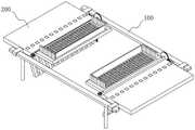
图1为本发明的整体结构示意图;Fig. 1 is the overall structure schematic diagram of the present invention;
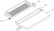
图2为本发明的整体结构拆分图;Fig. 2 is the overall structure disassembly drawing of the present invention;
图3为本发明的体脂检测机构结构示意图;3 is a schematic structural diagram of a body fat detection mechanism of the present invention;
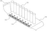
图4为本发明的功能板结构示意图;4 is a schematic structural diagram of a functional board of the present invention;
图5为本发明的检测板结构示意图;5 is a schematic structural diagram of a detection board of the present invention;
图6为本发明的传动件结构示意图;6 is a schematic structural diagram of a transmission member of the present invention;
图7为本发明的检测板和功能板侧面结构示意图;Fig. 7 is the side structure schematic diagram of the detection board and the function board of the present invention;
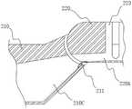
图8为本发明的功能件结构示意图其一;FIG. 8 is the first schematic diagram of the structure of the functional component of the present invention;
图9为本发明的功能件结构示意图其二;FIG. 9 is the second schematic diagram of the structure of the functional component of the present invention;
图10为本发明的储存腔结构示意图。FIG. 10 is a schematic diagram of the structure of the storage cavity of the present invention.
图中各个标号意义为:The meanings of the symbols in the figure are:
100、支撑机构;110、横板;120、支撑柱;130、滑块;100, support mechanism; 110, horizontal plate; 120, support column; 130, slider;
200、体脂检测机构;200. Body fat testing institutions;
210、检测板;211、密封板;210A、电极板;210B、导线;210C、储存腔;210, detection plate; 211, sealing plate; 210A, electrode plate; 210B, lead wire; 210C, storage cavity;
220、功能板;221、侧柱;222、挡板;223、排泄口;224、功能件;2241、“U”形管体;2242、加热网;2243、负压扇;2244、槽口;2245、引流板;224A、泄流槽;224B、柔性板;220A、泄流道;220, functional board; 221, side post; 222, baffle plate; 223, drain outlet; 224, functional part; 2241, "U"-shaped pipe body; 2242, heating net; 2243, negative pressure fan; 2244, notch; 2245, drainage plate; 224A, drainage groove; 224B, flexible plate; 220A, drainage channel;
230、转接板;230, adapter board;
240、伺服电机;240. Servo motor;
250、后挡组件;251、后挡板;252、受力齿板;253、齿轮组;2531、驱动齿轮;2532、受力齿轮;2533、传动齿轮。250, rear block assembly; 251, rear baffle; 252, force tooth plate; 253, gear set; 2531, drive gear; 2532, force gear; 2533, transmission gear.
具体实施方式Detailed ways
下面将结合本发明实施例中的附图,对本发明实施例中的技术方案进行清楚、完整地描述,显然,所描述的实施例仅仅是本发明一部分实施例,而不是全部的实施例。基于本发明中的实施例,本领域普通技术人员在没有做出创造性劳动前提下所获得的所有其他实施例,都属于本发明保护的范围。The technical solutions in the embodiments of the present invention will be clearly and completely described below with reference to the accompanying drawings in the embodiments of the present invention. Obviously, the described embodiments are only a part of the embodiments of the present invention, rather than all the embodiments. Based on the embodiments of the present invention, all other embodiments obtained by those of ordinary skill in the art without creative efforts shall fall within the protection scope of the present invention.
在本发明的描述中,需要理解的是,术语“中心”、“纵向”、“横向”、“长度”、“宽度”、“厚度”、“上”、“下”、“前”、“后”、“左”、“右”、“竖直”、“水平”、“顶”、“底”、“内”、“外”、“顺时针”、“逆时针”等指示的方位或位置关系为基于附图所示的方位或位置关系,仅是为了便于描述本发明和简化描述,而不是指示或暗示所指的设备或元件必须具有特定的方位、以特定的方位构造和操作,因此不能理解为对本发明的限制。In the description of the present invention, it should be understood that the terms "center", "longitudinal", "lateral", "length", "width", "thickness", "upper", "lower", "front", " rear, left, right, vertical, horizontal, top, bottom, inside, outside, clockwise, counterclockwise, etc., or The positional relationship is based on the orientation or positional relationship shown in the accompanying drawings, only for the convenience of describing the present invention and simplifying the description, rather than indicating or implying that the device or element referred to must have a specific orientation, be constructed and operated in a specific orientation, Therefore, it should not be construed as a limitation of the present invention.
此外,在本发明的描述中,“多个”的含义是两个或两个以上,除非另有明确具体的限定。In addition, in the description of the present invention, "plurality" means two or more, unless otherwise expressly and specifically defined.
实施例1Example 1
请参阅图1和图2所示,本实施例目的在于,提供了利用生物电阻抗原理实现的四肢定位式体脂检测结构,其包括支撑机构100和体脂检测机构200,支撑机构100包括两个横板110和设置在两个横板110底部的支撑柱120,支撑柱120设置的主要目的是对横板110进行支撑,横板110上滑动连接有滑块130,体脂检测机构200设置有两个,并且两个体脂检测机构200对称设置在两个横板110之间,具体的:Please refer to FIG. 1 and FIG. 2 , the purpose of this embodiment is to provide a limb positioning type body fat detection structure realized by the principle of bioelectrical impedance, which includes a
请参阅图3所示,体脂检测机构200包括检测板210和功能板220,本实施例中,检测板210与对应的滑块130固定连接,从而实现两个检测板210之间距离的调节,方便不同大小的羊进行体脂检测,另外,检测板210的一侧固定连接有转接板230,功能板220与转接板230之间通过转轴转动连接,转轴的一侧设置有伺服电机240,伺服电机240的输出端与转轴固定连接,其主要目的是驱动功能板220进行转动;Referring to FIG. 3 , the body
请参阅图5和图6所示,检测板210上设置有后挡组件250,后挡组件250包括后挡板251和受力齿板252,后挡板251向相对于功能板220的一侧倾斜,并与检测板210滑动连接,受力齿板252设置在后挡板251远离伺服电机240的一侧;Please refer to FIG. 5 and FIG. 6 , the
转轴的另一侧设置有齿轮组253,齿轮组253包括驱动齿轮2531,驱动齿轮2531的圆心处与转轴固定连接,驱动齿轮2531和受力齿板252之间设置有受力齿轮2532、传动齿轮2533,受力齿轮2532和传动齿轮2533同轴连接,受力齿轮2532与驱动齿轮2531啮合,传动齿轮2533与受力齿板252啮合,因此,当功能板220转动后,利用齿轮组253的配合驱动受力齿板252带动后挡板251同步上移,此时的后挡板251与功能板220之间呈“V”字形结构,用于对羊蹄的活动范围进行定位,并且检测板210顶部位于后挡板251和功能板220之间的区域设置有电极板210A,电极板210A的两侧设置有导线210B,同侧的两个检测板210之间利用横板110进行导通,从而实现羊体体脂的检测。The other side of the rotating shaft is provided with a
工作原理:working principle:
首先将羊体的前蹄和后蹄分别置于两个检测板210和功能板220形成的平台上,然后将伺服电机240接通电源,使其输出端工作带动功能板220转动,功能板220转动带动驱动齿轮2531转动,然后受力齿轮2532受到驱动齿轮2531带动传动齿轮2533同步转动,由于传动齿轮2533与受力齿板252啮合,所以受到啮合力的驱动受力齿板252会带动后挡板251同步上移,与功能板220形成一个“V”字形的定位槽,而后移动检测板210使滑块130在横板110上滑动,当功能板220与羊蹄面贴合后停止移动,并对滑块130进行固定,以通过定位槽对羊蹄进行定位,使其在定位的区域内活动,请参阅图7所示,定位的区域内设置有电极板210A,电极板210A通过羊蹄与羊体之间形成通路,从而实现对羊体的生物电阻的测量,然后通过测量的生物电阻检测出羊体的体脂,而且受到定位槽定位后,羊蹄无法进行前后移动,横向移动也都在电极板210A的范围内,进而实现降低电极板210A设置面积的同时不影响生物电阻的测量。First, place the front and rear hooves of the sheep's body on the platform formed by the two
值得说明的是,受力齿轮2532和传动齿轮2533的设置的目的是对驱动齿轮2531的驱动方向进行改变,从而保证功能板220向上转动的同时后挡板251能够上移,另外受力齿轮2532的半径小于传动齿轮2533,以增大受力齿轮2532驱动的线距离,从而实现功能板220小范围的转动对后挡板251产生大距离的驱动。It is worth noting that the purpose of setting the force-
实施例2Example 2
考虑到羊放置在检测板210和功能板220形成的平台上可能会乱跑,为了对平台上的羊进行初步限位,请参阅图4所示,功能板220的顶部两侧设置有多个侧柱221,功能板220顶部的外侧设置有挡板222,挡板222配合侧柱221在功能板220的三面形成限制面,以实现对羊的初步限制,而且当功能板220转动后,侧柱221可以对定位槽的两侧进行限制,挡板222则对羊的羊蹄进行限制,防止羊跳出。Considering that the sheep may run around when placed on the platform formed by the
实施例3Example 3
考虑到羊蹄上可能会携带泥土和水渍,为了对羊蹄上的泥土和水渍进行清理,请参阅图4所示,本实施例在功能板220的顶部呈矩形阵列设置有多个功能件224,请参阅图8所示,功能件224包括“U”形管体2241,“U”形管体2241的一侧端口上成环形阵列开设有多个槽口2244,其主要目的是形成多个吸入口,另一侧端口上设置加热网2242,加热网2242的底部设置有负压扇2243。Considering that the sheep's hooves may carry soil and water stains, in order to clean the soil and water stains on the sheep's hooves, please refer to FIG. 4 . In this embodiment, a plurality of
工作原理:working principle:
首先负压扇2243工作在槽口2244所在端口处形成一个向内吸的气流,以吸入经过该端口羊蹄上的泥土和水渍,考虑到羊蹄可能覆盖该端口,为此,设置的槽口2244形成的吸入口可以在覆盖时继续保持泥土的吸收,在此基础上还可以在该端口内设置引流板2245,引流板2245的横截面为开口向下的弧形结构,其主要目的是对羊蹄进行支撑,同时不影响槽口2244的通畅;First, the
与此同时,负压扇2243吸入的气流由“U”形管体2241的另一个端口排出,即:加热网2242所在侧,设有加热网2242会对吹出的气流进行加热,以达到对羊蹄进行烘干的目的,同时加热网2242也能对羊蹄进行支撑,所以羊在“U”形管体2241端口上行走时是不受影响的。At the same time, the air inhaled by the
实施例3Example 3
考虑到较大的水渍和泥土可能会直接附着在功能板220表面,为此,请参阅图4所示,在加热网2242所在侧上开设有排泄口223,且排泄口223的顶部设置隔网,其主要目的是方便羊进行行走,而且泥土和水渍也都能够进入到排泄口223内,防止泥土和水渍附着在功能板220表面影响检测结构。Considering that large water stains and soil may be directly attached to the surface of the
另外,为了对排泄口223进行利用,请参阅图9和图10所示,“U”形管体2241的底部开设有泄流槽224A,且泄流槽224A远离槽口2244的一侧设置有柔性板224B,当负压扇2243工作时,柔性板224B被吸起,然后泄流槽224A打开,这样槽口2244所在的端口吸入的泥土和水渍都流入泄流槽224A,而且本实施例中的排泄口223也均保持连通,这样流入泄流槽224A内的泥土和污渍都进入排泄口223,而检测板210内开设有储存腔210C,储存腔210C与排泄口223之间通过开设的泄流道220A连通,且泄流道220A和储存腔210C位于功能板220和检测板210的转接处设置有密封板211,密封板211为柔性结构,例如橡胶,密封板211对功能板220和检测板210转接处的缝隙进行密封,这样当功能板220转动后排泄口223内部的泥土和污渍都流入储存腔210C内,通过储存腔210C进行存储,以便于后期进行处理。In addition, in order to utilize the
以上显示和描述了本发明的基本原理、主要特征和本发明的优点。本行业的技术人员应该了解,本发明不受上述实施例的限制,上述实施例和说明书中描述的仅为本发明的优选例,并不用来限制本发明,在不脱离本发明精神和范围的前提下,本发明还会有各种变化和改进,这些变化和改进都落入要求保护的本发明范围内。本发明要求保护范围由所附的权利要求书及其等效物界定。The foregoing has shown and described the basic principles, main features and advantages of the present invention. Those skilled in the art should understand that the present invention is not limited by the above-mentioned embodiments, and the above-mentioned embodiments and descriptions are only preferred examples of the present invention, and are not intended to limit the present invention, without departing from the spirit and scope of the present invention. Under the premise, the present invention will also have various changes and improvements, and these changes and improvements all fall within the scope of the claimed invention. The claimed scope of the present invention is defined by the appended claims and their equivalents.
Claims (10)
Priority Applications (1)
| Application Number | Priority Date | Filing Date | Title |
|---|---|---|---|
| CN202210164011.8ACN114521885B (en) | 2022-02-22 | 2022-02-22 | Limb positioning body fat detection structure realized by bioelectrical impedance principle |
Applications Claiming Priority (1)
| Application Number | Priority Date | Filing Date | Title |
|---|---|---|---|
| CN202210164011.8ACN114521885B (en) | 2022-02-22 | 2022-02-22 | Limb positioning body fat detection structure realized by bioelectrical impedance principle |
Publications (2)
| Publication Number | Publication Date |
|---|---|
| CN114521885Atrue CN114521885A (en) | 2022-05-24 |
| CN114521885B CN114521885B (en) | 2024-10-18 |
Family
ID=81624594
Family Applications (1)
| Application Number | Title | Priority Date | Filing Date |
|---|---|---|---|
| CN202210164011.8AActiveCN114521885B (en) | 2022-02-22 | 2022-02-22 | Limb positioning body fat detection structure realized by bioelectrical impedance principle |
Country Status (1)
| Country | Link |
|---|---|
| CN (1) | CN114521885B (en) |
Citations (7)
| Publication number | Priority date | Publication date | Assignee | Title |
|---|---|---|---|---|
| US20090287076A1 (en)* | 2007-12-18 | 2009-11-19 | Boyden Edward S | System, devices, and methods for detecting occlusions in a biological subject |
| CN109444219A (en)* | 2018-12-25 | 2019-03-08 | 北京食安链科技有限公司 | A kind of quick detection probe of meat product nutritional quality and its detection method |
| CN208770050U (en)* | 2018-03-26 | 2019-04-23 | 新疆畜牧科学院畜牧研究所 | Sheep docking frame |
| CN111529118A (en)* | 2020-04-30 | 2020-08-14 | 宁陵县豫东牧业开发有限公司 | Movable type liftable sheep retaining frame |
| CN111826331A (en)* | 2020-08-13 | 2020-10-27 | 山西海洲生物科技有限公司 | A kind of microbial beneficial live bacteria agent for preventing fattening meat sheep yellow fat sheep and preparation method thereof |
| CN212686234U (en)* | 2020-06-19 | 2021-03-12 | 杨彦 | An edible oil transport device |
| CN113303282A (en)* | 2021-06-09 | 2021-08-27 | 临沂市农业科学院 | Method for improving early development of Qimeng black goats based on hybridization and mating device |
- 2022
- 2022-02-22CNCN202210164011.8Apatent/CN114521885B/enactiveActive
Patent Citations (7)
| Publication number | Priority date | Publication date | Assignee | Title |
|---|---|---|---|---|
| US20090287076A1 (en)* | 2007-12-18 | 2009-11-19 | Boyden Edward S | System, devices, and methods for detecting occlusions in a biological subject |
| CN208770050U (en)* | 2018-03-26 | 2019-04-23 | 新疆畜牧科学院畜牧研究所 | Sheep docking frame |
| CN109444219A (en)* | 2018-12-25 | 2019-03-08 | 北京食安链科技有限公司 | A kind of quick detection probe of meat product nutritional quality and its detection method |
| CN111529118A (en)* | 2020-04-30 | 2020-08-14 | 宁陵县豫东牧业开发有限公司 | Movable type liftable sheep retaining frame |
| CN212686234U (en)* | 2020-06-19 | 2021-03-12 | 杨彦 | An edible oil transport device |
| CN111826331A (en)* | 2020-08-13 | 2020-10-27 | 山西海洲生物科技有限公司 | A kind of microbial beneficial live bacteria agent for preventing fattening meat sheep yellow fat sheep and preparation method thereof |
| CN113303282A (en)* | 2021-06-09 | 2021-08-27 | 临沂市农业科学院 | Method for improving early development of Qimeng black goats based on hybridization and mating device |
Non-Patent Citations (1)
| Title |
|---|
| 薛白, 常祺, 李玉玲, 冶成君: "牦牛和藏羊蹄罐头营养含量测定及营养标签设计", 青海畜牧兽医杂志, no. 06, 30 December 2000 (2000-12-30)* |
Also Published As
| Publication number | Publication date |
|---|---|
| CN114521885B (en) | 2024-10-18 |
Similar Documents
| Publication | Publication Date | Title |
|---|---|---|
| JP2024543249A (en) | Urine volume monitoring system | |
| US20230097259A1 (en) | Generating device of simulating particulate environment for experimental animal | |
| WO2021189765A1 (en) | Floor brush of vacuum cleaner and vacuum cleaner | |
| CN114521885A (en) | Limb positioning type body fat detection structure realized by using bioelectrical impedance principle | |
| CN110101933B (en) | Portable anorectal surgery clinical flushing equipment | |
| CN113576687B (en) | Uropoiesis surgical instruments belt cleaning device | |
| CN221801118U (en) | Quick-dismantling type probe of medical sensor | |
| CN220773818U (en) | Comprehensive tear channel teaching aid | |
| CN109009123A (en) | Integrated gas path plate, gas treatment equipment and its Medical Devices | |
| CN115435715B (en) | Leaf area measuring device and measuring method for viburnum sargentii planting monitoring | |
| CN211325096U (en) | Convenient visual electronic measurement urine bag | |
| CN212853522U (en) | Catheterization sampling device for nephrology department | |
| CN211274740U (en) | Special test table that examines of multi-functional urological department | |
| CN215263538U (en) | Urine measuring device suitable for children of different age groups | |
| CN111990981A (en) | An electronic mercury sphygmomanometer | |
| CN216388507U (en) | A simulation model of vascular stenosis | |
| CN219956632U (en) | Precision metering bottle | |
| CN221980789U (en) | Urine collecting device and toilet | |
| CN218956592U (en) | A urine formed component analyzer | |
| CN219963558U (en) | Drainage bag | |
| CN113261937B (en) | An intelligent pressure measuring device during cerebrospinal fluid extraction | |
| CN213283101U (en) | Adjustable puncture device for nephrology department | |
| CN115024265B (en) | Fish counting device and counting method thereof | |
| CN112219774A (en) | Automatic fish sucking and screening machine for artificial breeding and seed selection of Pseudobagrus-selguchi fishes | |
| RU2008141291A (en) | SURGICAL CASSETTE WITH MULTI-ZONE LIQUID CAMERA |
Legal Events
| Date | Code | Title | Description |
|---|---|---|---|
| PB01 | Publication | ||
| PB01 | Publication | ||
| SE01 | Entry into force of request for substantive examination | ||
| SE01 | Entry into force of request for substantive examination | ||
| TA01 | Transfer of patent application right | Effective date of registration:20240717 Address after:No.2888, Xincheng street, Nanguan District, Changchun City, Jilin Province Applicant after:Shan Xuesong Country or region after:China Address before:130000 No. 2888 Xincheng street, Jilin, Changchun Applicant before:JILIN AGRICULTURAL University Country or region before:China | |
| TA01 | Transfer of patent application right | ||
| TA01 | Transfer of patent application right | Effective date of registration:20240918 Address after:No. 1-1, Building 1, No. 88 Fenghuang West Avenue, Guangxin District Economic and Technological Development Zone, Shangrao City, Jiangxi Province, China 333100 Applicant after:Shangrao Dasen Medical Technology Center (sole proprietorship) Country or region after:China Address before:No.2888, Xincheng street, Nanguan District, Changchun City, Jilin Province Applicant before:Shan Xuesong Country or region before:China | |
| TA01 | Transfer of patent application right | ||
| GR01 | Patent grant | ||
| GR01 | Patent grant |