CN114520524A - Power supply device, power supply method, and power supply system - Google Patents
Power supply device, power supply method, and power supply systemDownload PDFInfo
- Publication number
- CN114520524A CN114520524ACN202011303468.XACN202011303468ACN114520524ACN 114520524 ACN114520524 ACN 114520524ACN 202011303468 ACN202011303468 ACN 202011303468ACN 114520524 ACN114520524 ACN 114520524A
- Authority
- CN
- China
- Prior art keywords
- attribute information
- processor
- adapter
- protocol
- signal
- Prior art date
- Legal status (The legal status is an assumption and is not a legal conclusion. Google has not performed a legal analysis and makes no representation as to the accuracy of the status listed.)
- Granted
Links
Images


Classifications
- H—ELECTRICITY
- H02—GENERATION; CONVERSION OR DISTRIBUTION OF ELECTRIC POWER
- H02J—CIRCUIT ARRANGEMENTS OR SYSTEMS FOR SUPPLYING OR DISTRIBUTING ELECTRIC POWER; SYSTEMS FOR STORING ELECTRIC ENERGY
- H02J7/00—Circuit arrangements for charging or depolarising batteries or for supplying loads from batteries
- H02J7/00032—Circuit arrangements for charging or depolarising batteries or for supplying loads from batteries characterised by data exchange
- H02J7/00036—Charger exchanging data with battery
- H—ELECTRICITY
- H02—GENERATION; CONVERSION OR DISTRIBUTION OF ELECTRIC POWER
- H02J—CIRCUIT ARRANGEMENTS OR SYSTEMS FOR SUPPLYING OR DISTRIBUTING ELECTRIC POWER; SYSTEMS FOR STORING ELECTRIC ENERGY
- H02J7/00—Circuit arrangements for charging or depolarising batteries or for supplying loads from batteries
- H02J7/007—Regulation of charging or discharging current or voltage
- Y—GENERAL TAGGING OF NEW TECHNOLOGICAL DEVELOPMENTS; GENERAL TAGGING OF CROSS-SECTIONAL TECHNOLOGIES SPANNING OVER SEVERAL SECTIONS OF THE IPC; TECHNICAL SUBJECTS COVERED BY FORMER USPC CROSS-REFERENCE ART COLLECTIONS [XRACs] AND DIGESTS
- Y02—TECHNOLOGIES OR APPLICATIONS FOR MITIGATION OR ADAPTATION AGAINST CLIMATE CHANGE
- Y02E—REDUCTION OF GREENHOUSE GAS [GHG] EMISSIONS, RELATED TO ENERGY GENERATION, TRANSMISSION OR DISTRIBUTION
- Y02E60/00—Enabling technologies; Technologies with a potential or indirect contribution to GHG emissions mitigation
- Y02E60/10—Energy storage using batteries
Landscapes
- Engineering & Computer Science (AREA)
- Power Engineering (AREA)
- Charge And Discharge Circuits For Batteries Or The Like (AREA)
Abstract
Translated fromChinese
Description
Translated fromChinese技术领域technical field
本申请涉及充电技术领域,具体而言,涉及一种电源提供装置、电源提供方法和电源提供系统。The present application relates to the technical field of charging, and in particular, to a power supply device, a power supply method, and a power supply system.
背景技术Background technique
随着例如笔记本电脑、手机等便携式电子设备被广泛使用,便携式电子设备采用电池称作为电力系统,如何方便快捷的给电池充电的技术就变得较为重要。With the widespread use of portable electronic devices such as notebook computers and mobile phones, the portable electronic devices use a battery called a power system, and the technology of how to conveniently and quickly charge the battery becomes more important.
现有技术中的电源提供装置需要独立的MCU(Microcontroller Unit,微控制单元)处理器,成本较高,且占用面积较大。The power supply device in the prior art requires an independent MCU (Microcontroller Unit, Micro Control Unit) processor, which is costly and occupies a large area.
需要说明的是,在上述背景技术部分公开的信息仅用于加强对本公开的背景的理解,因此可以包括不构成对本领域普通技术人员已知的现有技术的信息。It should be noted that the information disclosed in the above Background section is only for enhancement of understanding of the background of the present disclosure, and therefore may contain information that does not form the prior art that is already known to a person of ordinary skill in the art.
发明内容SUMMARY OF THE INVENTION
本申请的目的在于提供一种电源提供装置和电源提供方法,进而至少在一定程度上克服现有技术中电源提供装置需要独立的MCU处理器,成本较高,成本较高,且占用面积较大。The purpose of the present application is to provide a power supply device and a power supply method, thereby at least to a certain extent overcome the need for an independent MCU processor in the power supply device in the prior art, the cost is high, the cost is high, and the occupied area is large .
根据本公开的第一方面,提供一种电源提供装置,所述电源提供装置基于待充电设备,所述待充电设备与外部适配器连接;所述电源提供装置包括:According to a first aspect of the present disclosure, a power supply device is provided, the power supply device is based on a device to be charged, and the device to be charged is connected to an external adapter; the power supply device includes:
处理器,接收电池的属性信息;The processor receives the attribute information of the battery;
充电控制器,连接于所述处理器、所述适配器以及所述电池;a charging controller connected to the processor, the adapter and the battery;
协议模块,集成于所述充电控制器,且与所述处理器和所述适配器连接,用于根据预设协议将所述属性信息传输至所述适配器以使得所述适配器能够根据所述属性信息调整输出信号,并向处理器反馈所述属性信息的传输完成信号,以使得所述处理器根据所述传输完成信号控制所述充电控制器生成闭合控制信号;a protocol module, integrated in the charging controller and connected with the processor and the adapter, for transmitting the attribute information to the adapter according to a preset protocol so that the adapter can use the attribute information according to the attribute information adjusting the output signal, and feeding back a transmission completion signal of the attribute information to the processor, so that the processor controls the charging controller to generate a closing control signal according to the transmission completion signal;
根据本申请的第二方面,提供一种电源提供方法,包括:According to a second aspect of the present application, a power supply method is provided, comprising:
通过处理器接收电池的属性信息;Receive battery attribute information through the processor;
通过集成于协议模块根据预设协议将所述属性信息传输至适配器以使得所述适配器能够根据所述属性信息调整输出信号,并向处理器反馈所述属性信息的传输完成信号,以使得所述处理器根据所述传输完成信号控制充电控制器生成闭合控制信号;The attribute information is transmitted to the adapter according to the preset protocol by being integrated in the protocol module, so that the adapter can adjust the output signal according to the attribute information, and feeds back the transmission completion signal of the attribute information to the processor, so that the The processor controls the charging controller to generate a closing control signal according to the transmission completion signal;
通过保护模块响应所述闭合控制信号,将所述输出信号传输至所述电池。The output signal is transmitted to the battery by a protection module in response to the closing control signal.
根据本申请的第三方面,提供一种电源提供系统,包括相互连接的待充电设备和适配器,其中,所述待充电设备包括处理器、充电控制器和保护模块;According to a third aspect of the present application, a power supply system is provided, including a device to be charged and an adapter connected to each other, wherein the device to be charged includes a processor, a charging controller, and a protection module;
其中,in,
所述处理器,接收电池的属性信息;the processor, receiving attribute information of the battery;
所述充电控制器,连接于所述处理器、所述适配器以及所述电池;the charging controller, connected to the processor, the adapter and the battery;
所述协议模块,集成于所述充电控制器,且与所述处理器和所述适配器连接,用于根据预设协议将所述属性信息传输至所述适配器以使得所述适配器能够根据所述属性信息调整输出信号,并向处理器反馈所述属性信息的传输完成信号,以使得所述处理器根据所述传输完成信号控制所述充电控制器生成闭合控制信号;The protocol module is integrated in the charging controller and connected with the processor and the adapter, and is used for transmitting the attribute information to the adapter according to a preset protocol so that the adapter can The attribute information adjusts the output signal, and feeds back a transmission completion signal of the attribute information to the processor, so that the processor controls the charging controller to generate a closing control signal according to the transmission completion signal;
所述保护模块,连接于所述适配器、所述电池以及所述充电控制器,用于响应所述闭合控制信号,将所述输出信号传输至所述电池。。The protection module is connected to the adapter, the battery and the charging controller, and is used for transmitting the output signal to the battery in response to the closing control signal. .
本申请的一种实施例所提供的电源提供装置、电源提供方法和电源提供系统,由处理器接收电池的属性信息并通过集成于充电控制器的协议模块将属性信息传输至适配器,适配器根据属性信息调整适配器的输出信号,并向处理器反馈属性信息的传输完成信号,以使得处理器根据传输完成信号控制充电控制器生成闭合控制信号,保护模块,连接于适配器、电池以及充电控制器,用于响应闭合控制信号,将输出信号传输至电池。相较于现有技术,无需采用独立的MCU来完成数据的处理,只需要在充点控制器一侧集成一协议模块完成通讯即可,数据处理过程由待充电设备中的处理器执行,简化了电源提供装置的复杂度,降低了成本,减少了电源提供装置的占用面积。In the power supply device, power supply method, and power supply system provided by an embodiment of the present application, the processor receives attribute information of the battery and transmits the attribute information to the adapter through a protocol module integrated in the charging controller. The information adjusts the output signal of the adapter, and feeds back the transmission completion signal of the attribute information to the processor, so that the processor controls the charging controller to generate a closing control signal according to the transmission completion signal, and the protection module is connected to the adapter, the battery and the charging controller. The output signal is transmitted to the battery in response to the closing control signal. Compared with the existing technology, there is no need to use an independent MCU to complete the data processing. It only needs to integrate a protocol module on the charging point controller side to complete the communication. The data processing process is performed by the processor in the device to be charged, which simplifies The complexity of the power supply device is reduced, the cost is reduced, and the occupied area of the power supply device is reduced.
应当理解的是,以上的一般描述和后文的细节描述仅是示例性和解释性的,并不能限制本申请。It is to be understood that both the foregoing general description and the following detailed description are exemplary and explanatory only and are not limiting of the present application.
附图说明Description of drawings
此处的附图被并入说明书中并构成本说明书的一部分,示出了符合本公开的实施例,并与说明书一起用于解释本公开的原理。显而易见地,下面描述中的附图仅仅是本公开的一些实施例,对于本领域普通技术人员来讲,在不付出创造性劳动的前提下,还可以根据这些附图获得其他的附图。在附图中:The accompanying drawings, which are incorporated in and constitute a part of this specification, illustrate embodiments consistent with the disclosure and together with the description serve to explain the principles of the disclosure. Obviously, the drawings in the following description are only some embodiments of the present disclosure, and for those of ordinary skill in the art, other drawings can also be obtained from these drawings without creative effort. In the attached image:
图1示出相关技术中电源提供装置的示意图;1 shows a schematic diagram of a power supply device in the related art;
图2示意性示出了本申请示例性实施例中一种电源提供装置的示意图;FIG. 2 schematically shows a schematic diagram of a power supply device in an exemplary embodiment of the present application;
图3示意性示出了本申请示例性实施例中对处理器进行细化后的电源提供装置的示意图;FIG. 3 schematically shows a schematic diagram of a power supply device after the processor is refined in an exemplary embodiment of the present application;
图4本申请示例性实施例中一种电源提供装置整体细化后的示意图;FIG. 4 is a schematic diagram of an overall refined power supply device in an exemplary embodiment of the present application;
图5示意性示出了本申请示例性实施例中根据预设协议将所述属性信息传输至所述适配器的数据流向图;FIG. 5 schematically shows a data flow diagram for transmitting the attribute information to the adapter according to a preset protocol in an exemplary embodiment of the present application;
图6示意性示出了本申请示例性实施例中对适配器进行细化后的电源提供装置的示意图;FIG. 6 schematically shows a schematic diagram of a power supply device after the adapter is refined in an exemplary embodiment of the present application;
图7示意性示出了本申请示例性实施例中适配器的具体结构示意图;FIG. 7 schematically shows a schematic diagram of a specific structure of an adapter in an exemplary embodiment of the present application;
图8示意性示出了本申请示例性实施例中一种电源提供方法的流程图;FIG. 8 schematically shows a flowchart of a power supply method in an exemplary embodiment of the present application;
图9示意性示出了本申请示例性实施例中根据预设协议将所述属性信息传输至所述适配器的流程图;FIG. 9 schematically shows a flowchart of transmitting the attribute information to the adapter according to a preset protocol in an exemplary embodiment of the present application;
图10示意性示出了本申请保护模块响应关断控制信号的流程图。FIG. 10 schematically shows a flow chart of the protection module of the present application responding to the shutdown control signal.
具体实施方式Detailed ways
现在将参考附图更全面地描述示例实施方式。然而,示例实施方式能够以多种形式实施,且不应被理解为限于在此阐述的范例;相反,提供这些实施方式使得本公开将更加全面和完整,并将示例实施方式的构思全面地传达给本领域的技术人员。所描述的特征、结构或特性可以以任何合适的方式结合在一个或更多实施方式中。Example embodiments will now be described more fully with reference to the accompanying drawings. Example embodiments, however, can be embodied in various forms and should not be construed as limited to the examples set forth herein; rather, these embodiments are provided so that this disclosure will be thorough and complete, and will fully convey the concept of example embodiments to those skilled in the art. The described features, structures, or characteristics may be combined in any suitable manner in one or more embodiments.
此外,附图仅为本公开的示意性图解,并非一定是按比例绘制。图中相同的附图标记表示相同或类似的部分,因而将省略对它们的重复描述。附图中所示的一些方框图是功能实体,不一定必须与物理或逻辑上独立的实体相对应。可以采用软件形式来实现这些功能实体,或在一个或多个硬件模块或集成电路中实现这些功能实体,或在不同网络和/或处理器装置和/或微控制器装置中实现这些功能实体。Furthermore, the drawings are merely schematic illustrations of the present disclosure and are not necessarily drawn to scale. The same reference numerals in the drawings denote the same or similar parts, and thus their repeated descriptions will be omitted. Some of the block diagrams shown in the figures are functional entities that do not necessarily necessarily correspond to physically or logically separate entities. These functional entities may be implemented in software, or in one or more hardware modules or integrated circuits, or in different networks and/or processor devices and/or microcontroller devices.
在相关技术中,参照图1所示,相关技术中的电源提供装置通过独立的MCU130以及数据采集模块150检测电池160的状态并与处理器140通讯,即检测电池160的属性信息,根据电池160状态与适配器110进行通讯,调整适配器110的输出电压和输出电流,控制电荷泵121启动开关晶体管,使得晶体管导通,来对电池160进行充电,在检测电池160的属性信息时,是由独立的MCU130以及待充设备中的处理器140中同时完成的。同时配置有充电控制器120,充电控制器通过PMIC(Power Management Integrated Circuit,电源管理集成电路)170与处理器140连接,适配器110通过通用异步收发传输线路连接于处理器,采用USB开关来控制线路的切换,在充电控制器120中设置有充电类型判断模块124来确定是否需要启动适配器110输出信号的信号流向。In the related art, as shown in FIG. 1 , the power supply device in the related art detects the state of the
相关技术中的电源提供装置采用独立的MCU处理器140成本较高,需要单独的固件维护,成本较高,且占用面积较大。The power supply device in the related art uses an
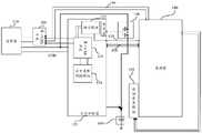
基于上述缺点,本申请首先提供一种电源提供装置,能够在一定程度上解决上述一个或多个问题,参照图2所示,电源提供装置基于待充电设备,待充电设备与外部适配器110连接;电源提供装置可以包括处理器140、充电控制器120、集成于充电控制器120的协议模块122以及保护模块180。其中处理器140接收电池160的属性信息;充电控制器120连接于处理器140、适配器110以及电池160;协议模块122集成于充电控制器120,且与处理器140和适配器110连接,用于根据预设协议将属性信息传输至适配器110以使得适配器110能够根据属性信息调整输出信号,并向处理器140反馈属性信息的传输完成信号,以使得处理器140根据传输完成信号控制充电控制器120生成闭合控制信号;保护模块180连接于适配器110、电池160以及协议模块122,用于响应闭合控制信号,将输出信号传输至电池160。Based on the above shortcomings, the present application first provides a power supply device, which can solve one or more of the above problems to a certain extent. Referring to FIG. 2 , the power supply device is based on the device to be charged, and the device to be charged is connected to the
相较于现有技术,无需采用独立的MCU来完成数据的处理,只需要在充点控制器112一侧集成一协议模块122完成通讯即可,数据处理过程由待充电设备中的处理器140执行,简化了电源提供装置的复杂度,降低了成本,减少了电源提供装置的占用面积。Compared with the prior art, there is no need to use an independent MCU to complete the data processing, only a
在申请的一种示例实施方式中,参照图3所示,处理器140集成于待充电设备中,待充电设备可以是笔记本电脑、手机、个人数字助理(PDA)等便携式电子设备。处理器140可以包括模数转换模块142和协议处理模块141,其中模数转换模块142用于对接收到的属性信息进行模数转换,协议处理模块141用于接收协议模块122的通讯信号根据预设协议将属性信息传输至适配器110。In an exemplary embodiment of the application, as shown in FIG. 3 , the
在本公开的一种示例实施方式中,上述电源提供装置还可以包括数据采集模块,上述数据采集模块150集成于上述待充电设备,用于采集电池160的属性信息并传输至处理器140。其中,属性信息可以包括电池160电压、电流、温度等信息,数据采集模块150可以包括电量计,还可以包括温度传感器、电压表、电流表等检测设备,在本示例实施方式中不做具体限定,随着需要检测的属性信息的数量的改变,可以数据采集模块150中设置与属性信息中的信息对应的检测设备,例如,需要检测电池160的剩余电量时,可以增加一个库仑计来检测。In an exemplary embodiment of the present disclosure, the above-mentioned power supply device may further include a data acquisition module. The above-mentioned
在本示例实施方式中,上述数据采集模块150可以通过I2C总线与上述处理器140连接,以用于将上述属性信息传输至处理器140。In this exemplary embodiment, the
在本示例实时方式中,数据采集模块150可以每隔一个预设时间便采集一次电池160的属性信息,上述预设时间可以为5毫秒、10毫秒等,也可以根据用户需求进行自定义,在本示例实施方式中不做具体限定。In the real-time mode of this example, the
在本示例实施方式中,处理器140接收数据采集模块150采集的属性信息后利用上述模数转换模块142对属性信息进行模数转换,,且处理器140可以保存预设次数的属性信息,预设数量可以是5次,即第六次采集到属性信息时,释放第一次采集的属性信息,预设数量还可以是10次、15次等,也可以根据用户需求进行自定义,在本示例实施方式中不做具体限定。In this exemplary embodiment, the
在本申请的一种示例实施方式中,协议模块122连接于上述处理器140和适配器110,用于根据预设协议将属性信号传输至适配器110,以使得所述适配器110能够根据所述属性信息调整输出信号,同时向处理器140反馈所述属性信息的传输完成信号,以使得所述处理器140根据所述传输完成信号控制充电控制器120生成闭合控制信号,其中,上述协议模块122可以通过数字电路状态机实现。In an exemplary implementation of the present application, the
在本示例实施方式中,电池160是蓄电池160,可以使用适配器110提供的充电电压对其进行再充电,电池160还可以由具有特定的电子电压的至少一个电池160单元形成,并能够输出电压。电池160供应关于电池160的数据信息,数据信息可以包含在上述属性信息中,数据信息可以包括电池160的完全充电比特,电池160的完全充电容量等。In this example embodiment, the
在本示例实施方式中,参照图4所示,协议模块122可以与上述处理器140通过数据传输线420以及中断线410连接;协议模块122可以与上述适配器110通过通用串行总线连接。其中数据传输线420可以是I2C总线、SPI总线(Serial Peripheral Interface,串行外设接口)或SPMI总线,在本示例实施方式中不做具体限定In this exemplary embodiment, referring to FIG. 4 , the
具体而言,参照图5所示,可以首先执行步骤S510,处理器140发送握手信号,在协议模块122接收到处理器140发送来的握手信号时,即表示充电接口已经连接在待充电设备,此时,可以执行步骤S520,可以将协议模块122已调整为空闲状态(IDLE状态)准备数据传输,同时,将握手信号发送给适配器110,适配器110接收到握手信号,后发出协议发送指令,在协议模块122接收到协议发送指令后,可以执行步骤S530,协议模块122跳转至数据接收状态(RECV_DATA状态),然后适配器110发送协议内容,其中该协议内容可以是需要接收的数据,即需要接收的数据包括上述属性信息中的一种或多种,协议内容中还可以为需要接收数据的位数,例如,接收8位数据、9位数据等,此时协议模块在接收属性信息是包括接收数据计数功能。Specifically, referring to FIG. 5 , step S510 may be executed first, and the
在协议模块122接收到协议内容之后,可以执行步骤S550,协议模块122跳转至等待数据发送状态(WAIT_TX_DATA状态),并向处理器140发送数据获取指令;处理器140在接收到数据获取指令之后,根据数据获取指令将属性信息发送至协议模块122,此时的属性信息中包括协议内容中所需的所有属性信息,例如,电池160电流,电池160温度等。在协议模块122接收到属性信息后,可以执行步骤S360,协议模块122跳转至数据发送状态(SEND_DATA状态),然后将属性信息发送至适配器110,然后跳转至空闲状态(IDLE状态)。After the
在本示例实施方式中,在上述协议模块122没有接收到处理器140发送的属性信息,或者接收的属性信息不完整时,即数据接收出错时,可以执行步骤S540,将所述协议模块122跳转至关闭状态(DISABLE状态),其中接收的属性信息不完整时,可以例如,协议内容中需要获取的数据包括电池160的电压、电流以及温度,但是接收到的属性信息只包括电池160的电压以及电流,没有温度信息,此时判定接收到的属性信息不完整。再例如,协议内容中需要接收的数据为8位数据,但是,协议模块122接收到的上述属性信息不够8位数据,例如6位数据、7位数据等,则可以执行步骤S540,将协议模块122跳转至关闭状态(DISABLE状态)。In this exemplary embodiment, when the above-mentioned
在本示例实施方式中,在协议模块122向适配器110发送属性信息时,当属性信息发送时,检测是否出现发送完成信号,即电信号在一定时间内为相同的电平信号,例如,在50毫秒内为低电平信号、40毫秒内容为高电平信号等。其中一定时间可以是50毫秒、40毫秒、60毫秒等,也可以根据用户需求进行自定义,相同的电平信号可以是高电平信号,也可以是低电平信号,在本示例实施方式中不做具体限定。In this exemplary embodiment, when the
在检测到出现发送完成信号时,表示数据发送正常且数据发送完成,则可以执行步骤S560,将协议模块122调跳转至空闲状态(IDLE状态),等待下一轮数据的接收。若在数据发送结束后,未接收到发送完成信号,即在发送相应位数的数据后,协议模块122还在发送数据,此时判定为发送属性信息异常,则可以执行步骤S540,将协议模块122跳转至关闭状态(DISABLE状态)。When a transmission completion signal is detected, it means that data transmission is normal and data transmission is completed, then step S560 may be executed to switch the
在本示例实施方式中,协议模块122可以接收处理器140发送的关闭信号,直接将协议模块122跳转至关闭状态(DISABLE状态)。在协议模块122处于关闭状态(DISABLE状态)时,可以响应处理器140发送的使能信号,将协议模块122跳转至空闲状态(IDLE状态)。In this exemplary embodiment, the
在本示例实施方式中,若上述属性信息的传输过程不存在异常,即适配器110接收到了完整的属性信息,则协议模块122向处理器140发送属性信息传输完成信号,并由处理器140控制充电控制器120生成闭合控制信号,若上述协议模块122出现关闭状态(DISABLE状态)时,协议模块122生成属性信息的传输失败信号,处理器140根据传输失败信号生成关断控制信号,停止充电以防止适配器110输出电压过高对电池160造成损坏。In this example embodiment, if there is no abnormality in the transmission process of the above attribute information, that is, the
在本示例实施方式中,参照图4所示,充电控制器120也是集成于上述待充电设备内部,待充电设备与上述适配器110通过USB接口连接,且在USB接口位置包括第一USB开关190,其中过上述第一USB开关190为分路开关元件,将线路分为两路,其中一路通过通用异步收发传输线路430(Universal Asynchronous Receiver/Transmitter)直接连接于处理器140,用于串口数据的传输,例如,下载文件至待充电设备,或者将文件由待充电设备上传。In this exemplary embodiment, referring to FIG. 4 , the charging
在本示例实施方式中,第一USB开关190的第二路连接于上述充电控制器120内部设置的第二USB开关123,第二USB开关123也可以是分路开关,分别连接于协议模块122以及上述充电类型判断模块124,在上述充电类型判断模块124判定USB接口连接的是适配器110时,将第二USB开关123连接至协议模块122,以完成适配器110与处理器140之间的通讯。In this exemplary embodiment, the second path of the
在本示例实施方式中,充电控制器120可以用于在适配器110与处理器140不适配时,即处理器140无法通过协议模块122将属性信息传输至适配器110时,将适配器110的输出信号转换为预设输入信号并传输电池160,其中上述预设输入信号可以是5V、2A的电信号,也可以根据适配器110和电池160的不同来设置上述预设输入信号,例如将上述预设输入信号设置为5V、1.5A,在本示例实施方式中不做具体限定。In this example embodiment, the charging
通过充电控制器120可以保证处理器140无法将属性信息传输至适配器110时,还能够继续对电池160进行充电,且保证了充电的安全性。The charging
在本示例实施方式中,参照图4所示,上述充电控制器120中还可以包括一驱动信号能够模块,用于接受处理器140的指令并生成闭合控制信号或者关断控制信号,其中,上述驱动信号生成模块可以是电荷泵121,用于在处理器140接收到属性信息的传输完成信号时,控制电荷泵121生成闭合及控制信号;使得保护模块180导通,进而使得输出信号能够经过保护模块180传输至电池160。或者用于在处理器140接收到属性信息传输失败信号时,处理器140控制电荷泵121生成关控制信号,使得保护模块180无法通过电流,对电池160进行保护。In the present exemplary embodiment, referring to FIG. 4 , the above-mentioned
在本示例实施方式中,参照图4所示,保护模块180可以包括至少一个开关晶体管,例如两个,三个等,在本示例实施方式中不做具体限定,其中开关晶体管均具有控制端、第一端、第二端。具体的,开关晶体管的控制端可以为栅极、第一端可以为源极、第二端可以为漏极;或者开关晶体管的控制端可以栅极、第一端可以为漏极、第二端可以为源极。此外,开关晶体管可以为增强型晶体管或者耗尽型晶体管,本示例性实施例中对此不做特殊限定。In this exemplary embodiment, referring to FIG. 4 , the
在本示例实施方式中,开关晶体管连接于上述驱动信号生成模块,开关晶体管的数量为两个时,两个开关晶体管的控制端均连接于驱动信号生成模块,第一开关晶体管的第一端链接于适配器110,第二端连接于第二开关晶体管的第一端,第二开关晶体管的第二端连接于电池160。开关元件可以响应闭合控制信号,控制开关元件导通,在接收到关断控制信号时,关断开关元件。In this exemplary embodiment, the switching transistor is connected to the above-mentioned driving signal generating module. When the number of switching transistors is two, the control terminals of the two switching transistors are both connected to the driving signal generating module, and the first terminal of the first switching transistor is connected to the driving signal generating module. In the
在本示例实施方式中,参照图6所示,适配器110被提供商用AC(交流)功率,将商用AC功率转换为预定电压电平的DC(直流)功率,并向上述电池160提供DC功率。In this example embodiment, referring to FIG. 6 , the
按照本申请的一个实施例的适配器110可以包括AC/DC转换器111和适配器控制器112。The
AC/DC转换器111将所输入的AC功率转换为DC功率,并且输出该DC功率。AC/DC转换器111可以按照由控制器112提供的信号来选择性地将所输入的AC功率转换为对应于多个电压电平的一个特定电平的DC功率Va,并且输出该DC功率。从AC/DC转换器111输出的DC功率被输出到电池160。The AC/
控制器112根据从协议模块122得到的电子电压以及属性信息确定AC/DC转换器111的输出信号,即输出电压和输出电流。The
参考图7,适配器110包括:控制器112和AC/DC转换器111。其中,控制器112用于接收电池160的属性信息确定输出信号控制器112。例如可以通过独立的微控制单元(MicroControl Unit,MCU)实现。Referring to FIG. 7 , the
AC/DC转换器111与控制器112连接,用于根据控制器112的控制,调整适配器110的输出电压。The AC/
此外,如图7所示,适配器110还可以包括整流电路R1和电压转换模块S1。其中,整流电路R1用于将从AC接收的交流电压转换为直流电压,该直流电压如为脉动直流电压。In addition, as shown in FIG. 7 , the
此外,为了获得稳定的直流电压(如恒定直流电压),适配器110还可以进一步包括:滤波电路F1,连接于整流电路R1的输出端,用于对整流电路R1输出的直流电压进行滤波。In addition, in order to obtain a stable DC voltage (such as a constant DC voltage), the
需要说明的是,本申请不限定整流电路R1的具体电路结构,整流电路R1例如可以为通常使用的整流桥,或者也可以为其他可实现上述将交流电压转换为直流电压功能的其他电路。It should be noted that the present application does not limit the specific circuit structure of the rectifier circuit R1, and the rectifier circuit R1 can be, for example, a commonly used rectifier bridge, or other circuits that can realize the above-mentioned function of converting an AC voltage to a DC voltage.
综上所述,本示例性实施方式中,无需采用独立的MCU来完成数据的处理,只需要在少充点控制器112一侧集成一协议模块122完成通讯即可,数据处理过程由待充电设备中的处理器140执行,简化了电源提供装置的复杂度,降低了成本,减少了电源提供装置的占用面积。To sum up, in this exemplary embodiment, it is not necessary to use an independent MCU to complete the data processing, and it is only necessary to integrate a
进一步的,本申请还提供一种电源提供方法,参照图8所示,电源提供方法包括如下步骤:Further, the present application also provides a power supply method. Referring to FIG. 8 , the power supply method includes the following steps:
步骤S810,通过处理器接收电池的属性信息;Step S810, receiving attribute information of the battery through the processor;
步骤S820,通过协议模块根据预设协议将所述属性信息传输至适配器以使得所述适配器能够根据所述属性信息调整输出信号,并向处理器反馈所述属性信息的传输完成信号,以使得所述处理器根据所述传输完成信号控制充电控制器生成闭合控制信号;Step S820, transmit the attribute information to the adapter through the protocol module according to the preset protocol, so that the adapter can adjust the output signal according to the attribute information, and feed back the transmission completion signal of the attribute information to the processor, so that all The processor controls the charging controller to generate a closing control signal according to the transmission completion signal;
步骤S830,通过保护模块响应所述闭合控制信号,将所述输出信号传输至所述电池。Step S830, responding to the closing control signal through the protection module, and transmitting the output signal to the battery.
上述方法中各步骤的具体细节在装置部分实施方式中已经详细说明,未披露的细节内容可以参见装置部分的实施方式内容,因而不再赘述。The specific details of each step in the above method have been described in detail in the implementation of the device part, and for undisclosed details, please refer to the implementation content of the device part, and thus will not be repeated.
在本申请的一种示例实施方式中,参照图9所示,根据预设协议将所述属性信息传输至所述适配器可以包括步骤S910至步骤S950,具体如下:In an exemplary implementation of the present application, referring to FIG. 9 , transmitting the attribute information to the adapter according to a preset protocol may include steps S910 to S950, as follows:
步骤S910,接收处理器发出的握手信号,将协议模块调整为空闲状态;Step S910, receiving a handshake signal sent by the processor, and adjusting the protocol module to an idle state;
步骤S920,接收所述适配器发送的协议发送指令,将所述协议模块调整为数据接收状态;Step S920, receiving a protocol sending instruction sent by the adapter, and adjusting the protocol module to a data receiving state;
步骤S930,在接收到所述适配器发送的协议内容时,将所述协议模块调整为等待数据发送状态,并像所述处理器发送数据获取指令Step S930, when receiving the protocol content sent by the adapter, adjust the protocol module to a state of waiting for data transmission, and send a data acquisition instruction to the processor
步骤S940,接收所述处理器根据所述数据获取指令发送的属性信息,并将所述协议模块调整为数据发送状态;Step S940, receiving the attribute information sent by the processor according to the data acquisition instruction, and adjusting the protocol module to a data sending state;
步骤S950,将所述属性信息发送至所述适配器,并将所述协议模块调整为空闲状态。Step S950, sending the attribute information to the adapter, and adjusting the protocol module to an idle state.
具体而言,处理器140发送握手信号,在协议模块122接收到处理器140发送来的握手信号时,即表示充电接口已经连接在待充电设备,此时,可以将协议模块122已调整为空闲状态(IDLE状态)准备数据传输,同时,将握手信号发送给适配器110,适配器110接收到握手信号,后发出协议发送指令,在协议模块122接收到协议发送指令后,协议模块122跳转至数据接收状态(RECV_DATA状态),然后适配器110发送协议内容,其中该协议内容可以是需要接收的数据,即需要接收的数据包括上述属性信息中的一种或多种,协议内容中还可以为需要接收数据的位数,例如,接收8位数据、9位数据等,此时协议模块122在接收属性信息是包括接收数据计数功能。Specifically, the
在协议模块122接收到协议内容之后,协议模块122跳转至等待数据发送状态(WAIT_TX_DATA状态),并向处理器140发送数据获取指令;处理器140在接收到数据获取指令之后,根据数据获取指令将属性信息发送至协议模块122,此时的属性信息中包括协议内容中所需的所有属性信息,例如,电池160电流,电池160温度等。在协议模块122接收到属性信息后,协议模块122跳转至数据发送状态(SEND_DATA状态),然后将属性信息发送至适配器110,然后跳转至空闲状态(IDLE状态)。After the
在本示例实施方式中,参照图10所示,上述方法还包括步骤S1010至步骤S1020,具体如下,若所述适配器110未接收到所述属性信息,则向处理器140反馈所述属性信息的传输失败信号,以使得所述处理器140根据所述传输完成信号控制所述充电控制器120生成关断控制信号,具体可以包括下面的多种情况,在上述协议模块122没有接收到处理器140发送的属性信息,或者接收的属性信息不完整时,即数据接收出错时,将所述协议模块122跳转至关闭状态(DISABLE状态),其中接收的属性信息不完整时,可以例如,协议内容中需要获取的数据包括电池160的电压、电流以及温度,但是接收到的属性信息只包括电池160的电压以及电流,没有温度信息,此时判定接收到的属性信息不完整。再例如,协议内容中需要接收的数据为8位数据,但是,协议模块122接收到的上述属性信息不够8位数据,例如6位数据、7位数据等,将协议模块122跳转至关闭状态(DISABLE状态)。In this exemplary embodiment, referring to FIG. 10 , the above method further includes steps S1010 to S1020 . The details are as follows. If the
在本示例实施方式中,在协议模块122向适配器110发送属性信息时,当属性信息发送时,检测是否出现发送完成信号,即电信号在一定时间内为相同的电平信号,例如,在50毫秒内为低电平信号、40毫秒内容为高电平信号等。其中一定时间可以是50毫秒、40毫秒、60毫秒等,也可以根据用户需求进行自定义,相同的电平信号可以是高电平信号,也可以是低电平信号,在本示例实施方式中不做具体限定。In this exemplary embodiment, when the
在检测到出现发送完成信号时,表示数据发送正常且数据发送完成,将协议模块122调跳转至空闲状态(IDLE状态),等待下一轮数据的接收。若在数据发送结束后,未接收到发送完成信号,即在发送相应位数的数据后,协议模块122还在发送数据,此时判定为发送属性信息异常,将协议模块122跳转至关闭状态(DISABLE状态)。When a transmission completion signal is detected, it means that the data transmission is normal and the data transmission is completed, and the
在本示例实施方式中,协议模块122可以接收处理器140发送的关闭信号,直接将协议模块122跳转至关闭状态(DISABLE状态)。在协议模块122处于关闭状态(DISABLE状态)时,可以响应处理器140发送的使能信号,将协议模块122跳转至空闲状态(IDLE状态)。In this exemplary embodiment, the
在本示例实施方式中,则协议模块122向处理器140发送属性信息传输完成信号,并由处理器140控制充电控制器120生成闭合控制信号,若上述协议模块122出现关闭状态(DISABLE状态)时,协议模块122生成属性信息的传输失败信号,处理器140根据传输失败信号生成关断控制信号,停止充电以防止适配器110输出电压过高对电池160造成损坏。In this exemplary embodiment, the
保护模块180可以响应上述关断控制信号,使得上述保护模块180停止工作并出现断路,使得适配器110的输出信号无法传输到电池160,以保证电池160的安全。The
本公开还提供一种电源提供系统,电源提供装置基于待充电设备,待充电设备与外部适配器110连接;电源提供装置可以包括处理器140、充电控制器120、集成于充电控制器120的协议模块122以及保护模块180。其中处理器140接收电池160的属性信息;充电控制器120连接于处理器140、适配器110以及电池160;协议模块122集成于充电控制器120,且与处理器140和适配器110连接,用于根据预设协议将属性信息传输至适配器110以使得适配器110能够根据属性信息调整输出信号,并向处理器140反馈属性信息的传输完成信号,以使得处理器140根据传输完成信号控制充电控制器120生成闭合控制信号;保护模块180连接于适配器110、电池160以及协议模块122,用于响应闭合控制信号,将输出信号传输至电池160。The present disclosure also provides a power supply system. The power supply device is based on the device to be charged, and the device to be charged is connected to the
上述系统中的处理器140、适配器110、充电控制器120、协议模块122以及保护模块180的具体细节在装置部分的实施方式中已经详细说明,未披露的细节内容可以参见装置部分的实施方式内容,因而不再赘述。The specific details of the
本领域技术人员在考虑说明书及实践这里申请的发明后,将容易想到本申请的其他实施例。本申请旨在涵盖本申请的任何变型、用途或者适应性变化,这些变型、用途或者适应性变化遵循本申请的一般性原理并包括本申请未申请的本技术领域中的公知常识或惯用技术手段。说明书和实施例仅被视为示例性的,本申请的真正范围和精神由权利要求指出。Other embodiments of the present application will readily occur to those skilled in the art upon consideration of the specification and practice of the invention claimed herein. This application is intended to cover any variations, uses or adaptations of this application that follow the general principles of this application and include common knowledge or conventional techniques in the technical field to which this application is not filed . The specification and examples are to be regarded as exemplary only, with the true scope and spirit of the application being indicated by the claims.
应可理解的是,本发明不将其应用限制到本说明书提出的部件的详细结构和布置方式。本发明能够具有其他实施方式,并且能够以多种方式实现并且执行。前述变形形式和修改形式落在本发明的范围内。应可理解的是,本说明书申请和限定的本发明延伸到文中和/或附图中提到或明显的两个或两个以上单独特征的所有可替代组合。所有这些不同的组合构成本发明的多个可替代方面。本说明书所述的实施方式说明了已知用于实现本发明的最佳方式,并且将使本领域技术人员能够利用本发明。It should be understood that the present invention is not limited in its application to the detailed structure and arrangement of components set forth in this specification. The invention is capable of other embodiments, of being implemented and of being carried out in various ways. The aforementioned variations and modifications fall within the scope of the present invention. It will be understood that the invention claimed and defined in this specification extends to all alternative combinations of two or more of the individual features mentioned or evident in the text and/or drawings. All of these different combinations constitute various alternative aspects of the present invention. The embodiments described in this specification illustrate the best mode known for carrying out the invention, and will enable any person skilled in the art to utilize the invention.
Claims (20)
Priority Applications (1)
| Application Number | Priority Date | Filing Date | Title |
|---|---|---|---|
| CN202011303468.XACN114520524B (en) | 2020-11-19 | 2020-11-19 | Power supply device, power supply method and power supply system |
Applications Claiming Priority (1)
| Application Number | Priority Date | Filing Date | Title |
|---|---|---|---|
| CN202011303468.XACN114520524B (en) | 2020-11-19 | 2020-11-19 | Power supply device, power supply method and power supply system |
Publications (2)
| Publication Number | Publication Date |
|---|---|
| CN114520524Atrue CN114520524A (en) | 2022-05-20 |
| CN114520524B CN114520524B (en) | 2025-05-13 |
Family
ID=81595074
Family Applications (1)
| Application Number | Title | Priority Date | Filing Date |
|---|---|---|---|
| CN202011303468.XAActiveCN114520524B (en) | 2020-11-19 | 2020-11-19 | Power supply device, power supply method and power supply system |
Country Status (1)
| Country | Link |
|---|---|
| CN (1) | CN114520524B (en) |
Cited By (1)
| Publication number | Priority date | Publication date | Assignee | Title |
|---|---|---|---|---|
| CN113036859A (en)* | 2021-03-15 | 2021-06-25 | Oppo广东移动通信有限公司 | Power supply device, power supply method, and power supply system |
Citations (6)
| Publication number | Priority date | Publication date | Assignee | Title |
|---|---|---|---|---|
| DE102010043582A1 (en)* | 2010-11-08 | 2012-05-10 | Hilti Aktiengesellschaft | Mobile electrical device with charge level indicator and accumulator for this |
| CN104020422A (en)* | 2014-06-24 | 2014-09-03 | 上海大学 | UPS (Uninterrupted Power Supply) storage battery detection device |
| US20160344227A1 (en)* | 2014-01-28 | 2016-11-24 | Guangdong Oppo Mobile Telecommunications Corp., Ltd. | Terminal and battery charging control device and method therefor |
| CN107710550A (en)* | 2016-02-05 | 2018-02-16 | 广东欧珀移动通信有限公司 | For the charging system of terminal, charging method and power supply adaptor |
| CN109687545A (en)* | 2018-12-06 | 2019-04-26 | Oppo广东移动通信有限公司 | Charging control method and device, computer storage medium and mobile power supply |
| CN111201689A (en)* | 2017-12-11 | 2020-05-26 | 深圳市柔宇科技有限公司 | Electronic equipment and charging control method |
- 2020
- 2020-11-19CNCN202011303468.XApatent/CN114520524B/enactiveActive
Patent Citations (6)
| Publication number | Priority date | Publication date | Assignee | Title |
|---|---|---|---|---|
| DE102010043582A1 (en)* | 2010-11-08 | 2012-05-10 | Hilti Aktiengesellschaft | Mobile electrical device with charge level indicator and accumulator for this |
| US20160344227A1 (en)* | 2014-01-28 | 2016-11-24 | Guangdong Oppo Mobile Telecommunications Corp., Ltd. | Terminal and battery charging control device and method therefor |
| CN104020422A (en)* | 2014-06-24 | 2014-09-03 | 上海大学 | UPS (Uninterrupted Power Supply) storage battery detection device |
| CN107710550A (en)* | 2016-02-05 | 2018-02-16 | 广东欧珀移动通信有限公司 | For the charging system of terminal, charging method and power supply adaptor |
| CN111201689A (en)* | 2017-12-11 | 2020-05-26 | 深圳市柔宇科技有限公司 | Electronic equipment and charging control method |
| CN109687545A (en)* | 2018-12-06 | 2019-04-26 | Oppo广东移动通信有限公司 | Charging control method and device, computer storage medium and mobile power supply |
Cited By (2)
| Publication number | Priority date | Publication date | Assignee | Title |
|---|---|---|---|---|
| CN113036859A (en)* | 2021-03-15 | 2021-06-25 | Oppo广东移动通信有限公司 | Power supply device, power supply method, and power supply system |
| CN113036859B (en)* | 2021-03-15 | 2024-07-16 | Oppo广东移动通信有限公司 | Power supply device, power supply method, and power supply system |
Also Published As
| Publication number | Publication date |
|---|---|
| CN114520524B (en) | 2025-05-13 |
Similar Documents
| Publication | Publication Date | Title |
|---|---|---|
| US8788852B2 (en) | System and method for providing power through a reverse local data transfer connection | |
| EP3098931B1 (en) | Charging circuit and terminal | |
| WO2014075498A1 (en) | Charging management method, device and system | |
| US20160336779A1 (en) | Charging Method, Alternating Current Adaptor, Charging Management Device and Terminal | |
| JP6440986B2 (en) | Power supply apparatus, controller thereof, control method, and electronic apparatus using the same | |
| US20170005495A1 (en) | Method and apparatus for charging electronic device with usb connection | |
| US20120198250A1 (en) | Portable terminal equipment, a power supply system, and a power supply method and a power supply program for portable terminal equipment | |
| WO2017088138A1 (en) | Charging device for mobile terminal | |
| CN101415043A (en) | Mobile terminal aware of externally connected device and control method for the same | |
| CN108964182A (en) | The adjusting method and device of reverse charging equipment, reverse charging electric current | |
| US20180278082A1 (en) | Electronic device and charging method thereof | |
| CN109254210B (en) | Electronic equipment port type detection method and device, detection circuit and electronic equipment | |
| US20150349561A1 (en) | Charging an electrical device via a data interface | |
| EP3518371B1 (en) | Wireless charging device, system and method on the basis of back cover-type mobile power supply | |
| US20080012524A1 (en) | Chargeable electronic devices and direct current voltage supply systems | |
| CN215181883U (en) | Switching power supply system and its power transmission protocol chip | |
| CN106329618A (en) | Charger USB charging control circuit and terminal USB charging control circuit | |
| CN103855781B (en) | Charger and electronic installation | |
| CN103138321B (en) | Charger of integration network interface converting device | |
| US7654861B2 (en) | Connector and method thereof | |
| CN114256897A (en) | Power supply device, power supply method, and power supply system | |
| CN114520524A (en) | Power supply device, power supply method, and power supply system | |
| CN109522258A (en) | USB interface, electronic equipment, USB interface-based programming system and its method | |
| CN101286648A (en) | Battery charging device, its control method, and battery charging control device | |
| CN113113948B (en) | Power supply device, power supply method and power supply system |
Legal Events
| Date | Code | Title | Description |
|---|---|---|---|
| PB01 | Publication | ||
| PB01 | Publication | ||
| SE01 | Entry into force of request for substantive examination | ||
| SE01 | Entry into force of request for substantive examination | ||
| GR01 | Patent grant | ||
| GR01 | Patent grant |