Movatterモバイル変換


[0]ホーム

URL:


CN114519959A - Electronic equipment and supporting device thereof - Google Patents

Electronic equipment and supporting device thereof
Download PDF

Info

Publication number
CN114519959A
CN114519959ACN202011306951.3ACN202011306951ACN114519959ACN 114519959 ACN114519959 ACN 114519959ACN 202011306951 ACN202011306951 ACN 202011306951ACN 114519959 ACN114519959 ACN 114519959A
Authority
CN
China
Prior art keywords
support
supporting
slider
housing
assembly
Prior art date
Legal status (The legal status is an assumption and is not a legal conclusion. Google has not performed a legal analysis and makes no representation as to the accuracy of the status listed.)
Granted
Application number
CN202011306951.3A
Other languages
Chinese (zh)
Other versions
CN114519959B (en
Inventor
周友文
Current Assignee (The listed assignees may be inaccurate. Google has not performed a legal analysis and makes no representation or warranty as to the accuracy of the list.)
Guangdong Oppo Mobile Telecommunications Corp Ltd
Original Assignee
Guangdong Oppo Mobile Telecommunications Corp Ltd
Priority date (The priority date is an assumption and is not a legal conclusion. Google has not performed a legal analysis and makes no representation as to the accuracy of the date listed.)
Filing date
Publication date
Application filed by Guangdong Oppo Mobile Telecommunications Corp LtdfiledCriticalGuangdong Oppo Mobile Telecommunications Corp Ltd
Priority to CN202011306951.3ApriorityCriticalpatent/CN114519959B/en
Publication of CN114519959ApublicationCriticalpatent/CN114519959A/en
Application grantedgrantedCritical
Publication of CN114519959BpublicationCriticalpatent/CN114519959B/en
Activelegal-statusCriticalCurrent
Anticipated expirationlegal-statusCritical

Links

Images

Classifications

Landscapes

Abstract

The utility model relates to an electronic equipment and strutting arrangement thereof, this strutting arrangement includes the casing subassembly, first supporting component and second supporting component, the casing subassembly includes first casing and second casing, the one end and the first casing of first supporting component are connected, the other end and the second casing of first supporting component are connected, and set up to extend or shorten along first direction, so that the second casing can switch between expansion state or the state of drawing in for first casing, the second supporting component is connected with first supporting component, the second supporting component extends along the second direction crossing with first direction. The utility model provides a strutting arrangement is after it switches to the expansion state, and second supporting component and first supporting component mutually support in order to form netted, and then support flexible display module from two nonparallel directions in second direction and first direction respectively to improve strutting arrangement to the support effect of flexible display module.

Description

Translated fromChinese
电子设备及其支撑装置Electronic equipment and its supporting device

技术领域technical field

本申请涉及电子设备的技术领域,具体是涉及电子设备及其支撑装置。The present application relates to the technical field of electronic equipment, and in particular, to electronic equipment and a supporting device thereof.

背景技术Background technique

随着电子设备的不断普及,电子设备已经成为人们日常生活中不可或缺的社交、娱乐工具,人们对于电子设备的要求也越来越高。为了增加电子设备的多样性,提供别样的使用体验,设备厂商不仅相继推出了搭载全面屏、折叠屏的电子设备,还进一步推出了搭载卷绕屏的电子设备。With the continuous popularization of electronic equipment, electronic equipment has become an indispensable social and entertainment tool in people's daily life, and people's requirements for electronic equipment are getting higher and higher. In order to increase the diversity of electronic devices and provide a different user experience, device manufacturers have not only successively launched electronic devices equipped with full-screen and folding screens, but also further launched electronic devices equipped with rolling screens.

发明内容SUMMARY OF THE INVENTION

本申请实施例提供了一种应用于柔性显示模组的支撑装置,其中,该支撑装置包括壳体组件、第一支撑组件和第二支撑组件,壳体组件包括第一壳体和第二壳体,第一支撑组件的一端与第一壳体连接,第一支撑组件的另一端与第二壳体连接,并设置成能够沿第一方向伸长或者缩短,以使得第二壳体相对于第一壳体能够在展开状态或者收拢状态之间进行切换,第二支撑组件与第一支撑组件连接,第二支撑组件沿与第一方向相交的第二方向延伸;其中,支撑装置用于在展开状态下支撑柔性显示模组。An embodiment of the present application provides a support device applied to a flexible display module, wherein the support device includes a casing assembly, a first support assembly and a second support assembly, and the casing assembly includes a first casing and a second casing One end of the first support assembly is connected to the first casing, and the other end of the first support assembly is connected to the second casing, and is arranged to be able to extend or shorten along the first direction, so that the second casing is relatively The first housing can be switched between the unfolded state or the retracted state, the second support assembly is connected with the first support assembly, and the second support assembly extends along a second direction intersecting with the first direction; wherein, the support device is used for Supports the flexible display module in the unfolded state.

本申请实施例还提供了一种电子设备,其中,该电子设备包括柔性显示模组和上述支撑装置,柔性显示模组的一端与第二壳体连接,支撑装置设置成能够在展开状态下支撑柔性显示模组。An embodiment of the present application further provides an electronic device, wherein the electronic device includes a flexible display module and the above-mentioned support device, one end of the flexible display module is connected to the second housing, and the support device is configured to be able to support in an unfolded state Flexible display module.

本申请的有益效果是:本申请提供的支撑装置在其切换至展开状态之后,第二支撑组件与第一支撑组件相互配合以形成网状,进而分别从第二方向和第一方向两个不平行的方向支撑柔性显示模组,以改善支撑装置对柔性显示模组的支持效果。The beneficial effect of the present application is that: after the supporting device provided by the present application is switched to the unfolded state, the second supporting component and the first supporting component cooperate with each other to form a net shape, and then the second direction and the first direction are two different directions respectively. The flexible display module is supported in parallel directions to improve the supporting effect of the support device on the flexible display module.

附图说明Description of drawings

为了更清楚地说明本申请实施例中的技术方案,下面将对实施例描述中所需要使用的附图作简单地介绍,显而易见地,下面描述中的附图仅仅是本申请的一些实施例,对于本领域普通技术人员来讲,在不付出创造性劳动的前提下,还可以根据这些附图获得其他的附图。In order to illustrate the technical solutions in the embodiments of the present application more clearly, the following briefly introduces the drawings that are used in the description of the embodiments. Obviously, the drawings in the following description are only some embodiments of the present application. For those of ordinary skill in the art, other drawings can also be obtained from these drawings without creative effort.

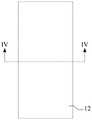
图1是本申请提供的电子设备一实施例的俯视结构示意图;1 is a schematic top-view structural diagram of an embodiment of an electronic device provided by the present application;

图2是图1中电子设备处于另一状态的俯视结构示意图;Fig. 2 is a top-view structural schematic diagram of the electronic device in another state in Fig. 1;

图3是图1中电子设备沿III-III方向的截面结构示意图;3 is a schematic cross-sectional structure diagram of the electronic device in the direction III-III in FIG. 1;

图4是图2中电子设备沿IV-IV方向的截面结构示意图;Fig. 4 is the cross-sectional structure schematic diagram of the electronic device in the IV-IV direction in Fig. 2;

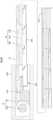
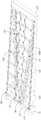
图5是图3中支撑装置一实施例在展开状态下的结构示意图;FIG. 5 is a schematic structural diagram of an embodiment of the support device in FIG. 3 in an unfolded state;

图6是图5中支撑装置在收拢状态下的结构示意图;FIG. 6 is a schematic structural diagram of the support device in FIG. 5 in a folded state;

图7是图5中顺次相连三个中间滑块的相对位置关系示意图;FIG. 7 is a schematic diagram of the relative positional relationship of three intermediate sliders connected in sequence in FIG. 5;

图8是图7中任意一个中间滑块沿VIII-VIII方向的截面结构示意图;FIG. 8 is a schematic cross-sectional structure diagram of any one of the intermediate sliders in FIG. 7 along the VIII-VIII direction;

图9是图5中第一支撑组件另一实施例在展开状态下的俯视结构示意图;FIG. 9 is a schematic top-view structural diagram of another embodiment of the first support assembly in FIG. 5 in an unfolded state;

图10是图9中任意一个中间滑块沿X-X方向的截面结构示意图;10 is a schematic cross-sectional structure diagram of any one of the intermediate sliders in FIG. 9 along the X-X direction;

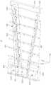
图11是图3中支撑装置另一实施例在展开状态下的结构示意图;FIG. 11 is a schematic structural diagram of another embodiment of the support device in FIG. 3 in an unfolded state;

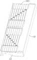
图12是图11中支撑装置在收拢状态下的结构示意图;Fig. 12 is a schematic structural diagram of the support device in Fig. 11 in a folded state;

图13是图11中局部区域XIII的结构示意图;Fig. 13 is the structural representation of partial area XIII in Fig. 11;

图14是图11中第二支撑杆一实施例的结构示意图。FIG. 14 is a schematic structural diagram of an embodiment of the second support rod in FIG. 11 .

具体实施方式Detailed ways

下面结合附图和实施例,对本申请作进一步的详细描述。特别指出的是,以下实施例仅用于说明本申请,但不对本申请的范围进行限定。同样的,以下实施例仅为本申请的部分实施例而非全部实施例,本领域普通技术人员在没有做出创造性劳动前提下所获得的所有其他实施例,都属于本申请保护的范围。The present application will be further described in detail below with reference to the accompanying drawings and embodiments. It is particularly pointed out that the following examples are only used to illustrate the present application, but do not limit the scope of the present application. Likewise, the following embodiments are only some of the embodiments of the present application but not all of the embodiments, and all other embodiments obtained by those of ordinary skill in the art without creative work fall within the protection scope of the present application.

本申请中提及“实施例”意味着,结合实施例描述的特定特征、结构或特性可以包含在本申请的至少一个实施例中。本领域技术人员显式地和隐式地理解的是,本申请所描述的实施例可以与其他实施例相结合。Reference in this application to an "embodiment" means that a particular feature, structure, or characteristic described in connection with the embodiment can be included in at least one embodiment of the application. It is explicitly and implicitly understood by those skilled in the art that the embodiments described in this application may be combined with other embodiments.

共同参阅图1至图4,图1是本申请提供的电子设备一实施例的俯视结构示意图,图2是图1中电子设备处于另一状态的俯视结构示意图,图3是图1中电子设备沿III-III方向的截面结构示意图,图4是图2中电子设备沿IV-IV方向的截面结构示意图。需要说明的是:图1所示的电子设备可以与本申请所述的支撑装置呈展开状态相对应,图2所示的电子设备可以与上述支撑装置呈收拢状态相对应。另外,由于电子设备在展开状态下沿第一方向的尺寸较大,所以图3所示的电子设备被一分为二,并用双点划线示意两部分的拼接关系。进一步地,本申请中所有方向性指示(诸如上、下、左、右、前、后……)仅用于解释在某一特定姿态(如附图1所示)下各部件之间的相对位置关系、运动情况等,如果该特定姿态发生改变时,则该方向性指示也相应地随之改变。其中,图1中箭头X所示的方向可以简单地视作本申请所述的第一方向,图1中箭头Y所示的方向可以简单地视作本申请所述的第二方向,图1中箭头Z所示的方向可以简单地视作本申请所述的第三方向。Referring to FIGS. 1 to 4 together, FIG. 1 is a schematic top-view structure diagram of an embodiment of an electronic device provided by the present application, FIG. 2 is a top-view structure schematic diagram of the electronic device in FIG. 1 in another state, and FIG. 3 is the electronic device in FIG. 1 . A schematic diagram of a cross-sectional structure along the direction of III-III, FIG. 4 is a schematic diagram of a cross-sectional structure of the electronic device in the direction of IV-IV in FIG. 2 . It should be noted that the electronic device shown in FIG. 1 may correspond to the supporting device described in the present application in an unfolded state, and the electronic device shown in FIG. 2 may correspond to the supporting device in a retracted state. In addition, since the size of the electronic device along the first direction in the unfolded state is relatively large, the electronic device shown in FIG. 3 is divided into two parts, and the splicing relationship of the two parts is indicated by a dashed-dotted line. Further, all directional indications (such as up, down, left, right, front, rear...) in this application are only used to explain the relative relationship between various components in a certain posture (as shown in FIG. 1 ). If the specific posture changes, the directional indication also changes accordingly. The direction indicated by the arrow X in FIG. 1 can be simply regarded as the first direction described in the present application, and the direction indicated by the arrow Y in FIG. 1 can be simply regarded as the second direction described in the present application. The direction indicated by the arrow Z in the middle can be simply regarded as the third direction described in this application.

结合图1至图4,电子设备10可以包括组装在一起的柔性显示模组11、壳体组件12、收卷组件13和支撑装置14。其中,结合图1及图3,当用户需要与电子设备10进行交互时,支撑装置14可以沿第一方向至少部分伸出壳体组件12而切换至展开状态;柔性显示模组11也可以随之展开而铺展在支撑装置14上。进一步地,结合图2及图4,当用户不需要与电子设备10进行交互时,支撑装置14可以缩回壳体组件12而切换至收拢状态;柔性显示模组11也可以在收卷组件13的作用下随之收卷而收纳在壳体组件12内。换言之,柔性显示模组11可以随支撑装置14在展开状态或者收拢状态之间进行切换。Referring to FIGS. 1 to 4 , theelectronic device 10 may include aflexible display module 11 , ahousing assembly 12 , awinding assembly 13 and a supportingdevice 14 that are assembled together. 1 and 3, when the user needs to interact with theelectronic device 10, thesupport device 14 can at least partially protrude from thehousing assembly 12 along the first direction to switch to the unfolded state; theflexible display module 11 can also follow the It is unfolded and spread on thesupport device 14 . Further, with reference to FIG. 2 and FIG. 4 , when the user does not need to interact with theelectronic device 10 , thesupport device 14 can retract thehousing assembly 12 to switch to the folded state; theflexible display module 11 can also be in theretracting assembly 13 . Under the action of the device, it is rolled up and stored in thehousing assembly 12 . In other words, theflexible display module 11 can be switched between the unfolded state or the folded state with thesupport device 14 .

需要说明的是:当柔性显示模组11铺展在支撑装置14上之后,柔性显示模组11可以具有一定的张力,使之能够平整地铺展在支撑装置14上。当然,支撑装置14和柔性显示模组11上还可以分别设置有极性互异的磁吸件,以使得柔性显示模组11在展开状态下能够与支撑装置14彼此磁性吸附。It should be noted that: after theflexible display module 11 is spread on thesupport device 14 , theflexible display module 11 may have a certain tension so that it can be spread on thesupport device 14 flatly. Of course, thesupport device 14 and theflexible display module 11 may also be provided with magnetic attraction parts with different polarities, so that theflexible display module 11 and thesupport device 14 can be magnetically attracted to each other in the unfolded state.

一般地,柔性显示模组11可以是LCD(Liquid Crystal Display)这类显示屏,也可以是OLED(Organic Light Emitting Diode)、QLED(Quantum Dot Light Emitting Diode)这类显示屏,还可以是Mini-LED、Micro-LED这类显示屏。其中,本申请以柔性显示模组11为OLED这类显示屏为例进行示例性的说明。Generally, theflexible display module 11 may be a display screen such as an LCD (Liquid Crystal Display), a display screen such as an OLED (Organic Light Emitting Diode), a QLED (Quantum Dot Light Emitting Diode), or a Mini- Displays such as LED and Micro-LED. Wherein, the present application exemplifies the case where theflexible display module 11 is a display screen such as an OLED.

结合图3及图4,壳体组件12可以包括第一壳体121、第二壳体122和第三壳体123。其中,第一壳体121和第二壳体122可以分别与支撑装置14的两端一一对应连接,以使得第一壳体121和第二壳体122既能够随支撑装置14的展开而彼此背离,又能够随支撑装置14的收拢而彼此靠近。进一步地,第三壳体123可以与第一壳体121连接,并可以围设形成一开口方向沿第一方向的收容腔124。此时,支撑装置14可以在收拢状态下收容在收容腔124内,并可以在展开状态下至少部分伸出收容腔124。除此之外,收卷组件13及其他诸如电池、主板、摄像头等结构件也可以收容在收容腔124内。换言之,第三壳体123可以简单地视作电子设备10的外壳,以保护电子设备10的内部结构。3 and 4 , thehousing assembly 12 may include afirst housing 121 , asecond housing 122 and athird housing 123 . Wherein, thefirst shell 121 and thesecond shell 122 can be respectively connected with the two ends of thesupport device 14 in a one-to-one correspondence, so that thefirst shell 121 and thesecond shell 122 can be connected to each other with the expansion of thesupport device 14 . Deviating from each other, they can approach each other as thesupport device 14 is retracted. Further, thethird casing 123 can be connected with thefirst casing 121 and can enclose areceiving cavity 124 with an opening direction along the first direction. At this time, thesupport device 14 can be accommodated in theaccommodating cavity 124 in the folded state, and can at least partially extend out of theaccommodating cavity 124 in the unfolded state. Besides, thewinding assembly 13 and other structural components such as batteries, motherboards, cameras and the like can also be accommodated in theaccommodating cavity 124 . In other words, thethird casing 123 can be simply regarded as a casing of theelectronic device 10 to protect the internal structure of theelectronic device 10 .

作为示例地,结合图4及图5,第一壳体121可以包括一体连接的第一底部1211和两个沿第二方向相对设置的第一侧部1212。其中,两个第一侧部1212可以分别与第一底部1211弯折连接,并可以沿第三方向同向延伸,以围设形成第一避让槽1213。换言之,第一壳体121可以呈U字型。此时,支撑装置14的一端可以与第一底部1211连接,并可以收拢在第一避让槽1213内而呈收拢状态。其中,在第三方向上,第一避让槽1213的深度可以等于支撑装置14的厚度,以便于控制电子设备10的整体厚度。As an example, with reference to FIGS. 4 and 5 , thefirst housing 121 may include afirst bottom 1211 integrally connected and twofirst side portions 1212 oppositely disposed along the second direction. Wherein, the twofirst side portions 1212 can be respectively connected to thefirst bottom portion 1211 by bending, and can extend in the same direction along the third direction, so as to enclose and form thefirst avoidance groove 1213 . In other words, thefirst casing 121 may have a U-shape. At this time, one end of thesupport device 14 can be connected to thefirst bottom portion 1211 , and can be folded in thefirst escape groove 1213 to be in a folded state. Wherein, in the third direction, the depth of thefirst escape groove 1213 may be equal to the thickness of thesupport device 14 , so as to control the overall thickness of theelectronic device 10 .

作为示例性地,结合图4及图5,第二壳体122可以包括一体连接的第二底部1221和第二侧部1222。其中,第二侧部1222可以与第二底部1221弯折连接。换言之,第二壳体122可以呈L字型。此时,支撑装置14背离第一壳体121的另一端可以与第二底部1221连接。如此设置,第二侧部1222可以在第一方向上遮蔽支撑装置14,进而改善电子设备10的外观表现力。相应地,用户也可以通过对第二侧部1222施加作用力而使得第二壳体122朝着背离第一壳体121的方向运动,进而带动支撑装置14沿第一方向展开。进一步地,柔性显示模组11背离第一壳体121的一端可以与第二壳体122(具体可以为第二底部1221)连接,以使得柔性显示模组11能够随支撑装置14的展开而同步地铺展在支撑装置14上。其中,柔性显示模组11与支撑装置14可以分别位于第二底部1221相背的两侧,以使得两者在结构上能够互不干扰。此时,第二底部1221与柔性显示模组11接触的一面可以尽可能的平整,以更好地支撑柔性显示模组11。As an example, with reference to FIGS. 4 and 5 , thesecond housing 122 may include asecond bottom 1221 and asecond side 1222 that are integrally connected. Thesecond side portion 1222 may be connected to thesecond bottom portion 1221 by bending. In other words, thesecond casing 122 may have an L-shape. At this time, the other end of thesupport device 14 facing away from thefirst casing 121 may be connected to thesecond bottom 1221 . In this way, thesecond side portion 1222 can shield thesupport device 14 in the first direction, thereby improving the appearance of theelectronic device 10 . Correspondingly, the user can also make thesecond casing 122 move in a direction away from thefirst casing 121 by exerting force on thesecond side portion 1222 , thereby driving thesupport device 14 to unfold in the first direction. Further, the end of theflexible display module 11 facing away from thefirst casing 121 can be connected to the second casing 122 (specifically, the second bottom 1221 ), so that theflexible display module 11 can be synchronized with the expansion of thesupport device 14 The ground is spread on thesupport device 14 . Wherein, theflexible display module 11 and the supportingdevice 14 may be located on opposite sides of thesecond bottom 1221 respectively, so that the two can not interfere with each other in structure. At this time, the side of the second bottom 1221 in contact with theflexible display module 11 may be as flat as possible to better support theflexible display module 11 .

一般地,对于传统的搭载全面屏、折叠屏的电子设备而言,电子设备的体积大体是固定不变的。然而,对于搭载卷绕屏的电子设备而言,电子设备的体积会随着展开状态或者收拢状态之间的切换而相应地变大或者变小。此时,在柔性显示模组11能够随支撑装置14而展开或者收卷的过程中,壳体组件12也最好能够随之发生结构上的改变,以便于保护电子设备10的内部结构。为此,结合图3及图4,壳体组件12还可以包括连接在第一壳体121和第二壳体122之间的中间壳体125,中间壳体125设置成能够沿第一方向相对于第一壳体121和第二壳体122滑动。例如:第一壳体121、中间壳体125和第二壳体122顺次至少部分层叠,并通过滑轨与滑槽的配合方式而两两滑动连接。再例如:中间壳体125可以与支撑装置14连接,两者同步运动。如此设置,在第一壳体121和第二壳体122随支撑装置14的展开而彼此背离的过程中,中间壳体125能够随之运动而补齐第一壳体121和第二壳体122之间的空隙,以使得电子设备10不论在什么情况下均能够被壳体组件12保护。当然,在第一壳体121和第二壳体122随支撑装置14的收拢而彼此靠近的过程中,中间壳体125也能够随之运动而层叠在第一壳体121和第二壳体122之间。Generally, for a traditional electronic device equipped with a full screen and a folding screen, the volume of the electronic device is generally fixed. However, for an electronic device equipped with a roll-up screen, the volume of the electronic device will correspondingly increase or decrease with the switch between the unfolded state or the folded state. At this time, when theflexible display module 11 can be unfolded or retracted with thesupport device 14 , thecasing assembly 12 preferably can also undergo structural changes, so as to protect the internal structure of theelectronic device 10 . To this end, referring to FIG. 3 and FIG. 4 , thehousing assembly 12 may further include amiddle housing 125 connected between thefirst housing 121 and thesecond housing 122 , and themiddle housing 125 is arranged to be able to face each other along the first direction. It slides on thefirst casing 121 and thesecond casing 122 . For example, thefirst shell 121 , themiddle shell 125 and thesecond shell 122 are at least partially stacked in sequence, and are slidably connected in pairs through the cooperation of the sliding rails and the sliding grooves. For another example, theintermediate housing 125 may be connected with the supportingdevice 14, and the two move synchronously. In this way, when thefirst shell 121 and thesecond shell 122 are separated from each other with the expansion of thesupport device 14 , themiddle shell 125 can move accordingly to complement thefirst shell 121 and thesecond shell 122 space therebetween so that theelectronic device 10 can be protected by thehousing assembly 12 no matter what. Of course, in the process of thefirst shell 121 and thesecond shell 122 approaching each other as thesupport device 14 is folded, themiddle shell 125 can also move along with it to be stacked on thefirst shell 121 and thesecond shell 122 between.

作为示例性地,结合图4及图11,中间壳体125的数量可以为多个,多个中间壳体125顺次连接在第一壳体121和第二壳体122之间,并设置成能够沿第一方向彼此相对滑动。其中,每一中间壳体125均可以呈U字型,其大小也可以逐渐变化,以使得每一中间壳体125均能够收纳前一中间壳体125并能够被后一中间壳体125收纳。换言之,多个中间壳体125可以形成类似于“俄罗斯套娃”的结构。如此设置,电子设备10展开之后,不论第一壳体121和第二壳体122之间的空隙有多大,该空隙均可以通过多个中间壳体125之间的相互配合而被补齐,以使得电子设备10不论在什么情况下均能够被壳体组件12保护。As an example, referring to FIG. 4 and FIG. 11 , the number of theintermediate casings 125 may be multiple, and the multipleintermediate casings 125 are sequentially connected between thefirst casing 121 and thesecond casing 122 and are arranged to are slidable relative to each other in a first direction. Wherein, eachintermediate casing 125 can be U-shaped, and its size can also be gradually changed, so that eachintermediate casing 125 can accommodate the previousintermediate casing 125 and can be accommodated by the latterintermediate casing 125 . In other words, the plurality ofintermediate casings 125 may form a structure similar to a "Matryoshka doll". In this way, after theelectronic device 10 is unfolded, no matter how large the gap between thefirst shell 121 and thesecond shell 122 is, the gap can be filled by the mutual cooperation between the plurality ofmiddle shells 125, so as to This enables theelectronic device 10 to be protected by thehousing assembly 12 under any circumstances.

需要说明的是:本申请的描述中,“多个”的含义是至少两个,例如两个,三个等,除非另有明确具体的限定。It should be noted that: in the description of this application, the meaning of "plurality" is at least two, such as two, three, etc., unless otherwise expressly and specifically defined.

对于电子设备10而言,柔性显示模组11和壳体组件12往往设置在电子设备10相背的正反两面。基于此,第一底部1211背离第一侧部1212的一侧还可以部分凹陷以形成第二避让槽1214。此时,多个中间壳体125中的第一个(或者倒数第一个)可以与第一底部1211连接,剩余的中间壳体125也可以顺次层叠式地收纳在第二避让槽1214内而呈收拢状态。其中,在第三方向上,第二避让槽1214的深度可以等于多个中间壳体125的层叠高度,以便于控制电子设备10的整体厚度。For theelectronic device 10 , theflexible display module 11 and thehousing assembly 12 are often disposed on the opposite sides of theelectronic device 10 . Based on this, the side of thefirst bottom portion 1211 away from thefirst side portion 1212 may also be partially recessed to form thesecond escape groove 1214 . At this time, the first (or the last one) of the plurality ofintermediate casings 125 can be connected to thefirst bottom 1211 , and the remainingintermediate casings 125 can also be stored in thesecond avoidance groove 1214 in a stacked manner. in a folded state. Wherein, in the third direction, the depth of thesecond avoidance groove 1214 may be equal to the stacking height of the plurality ofintermediate casings 125 , so as to control the overall thickness of theelectronic device 10 .

再次结合图3及图4,收卷组件13可以设置在第一壳体121一侧,并可以包括收卷支架131和收卷轴132。其中,收卷支架131位于第一壳体121背离第二壳体122的一侧,并可以与第一壳体121连接,以架设收卷轴132。进一步地,柔性显示模组11背离第二壳体122的另一端可以与收卷组件13连接,收卷组件13配置成能够在展开状态切换至收拢状态的过程中收卷柔性显示模组11。作为示例性地,柔性显示模组11背离第二壳体122的另一端与收卷轴132连接,以在展开状态切换至收拢状态的过程中,收卷轴132能够在伺服电机等驱动件(图中未示出)的驱动作用下转动而收卷柔性显示模组11。Referring to FIGS. 3 and 4 again, the windingassembly 13 may be disposed on one side of thefirst housing 121 , and may include a windingsupport 131 and a windingshaft 132 . The windingsupport 131 is located on the side of thefirst casing 121 away from thesecond casing 122 , and can be connected with thefirst casing 121 to set up the windingshaft 132 . Further, the other end of theflexible display module 11 facing away from thesecond casing 122 can be connected to the windingassembly 13 , and the windingassembly 13 is configured to be able to wind theflexible display module 11 during the process of switching from the unfolded state to the folded state. As an example, the other end of theflexible display module 11 facing away from thesecond casing 122 is connected to the windingshaft 132, so that during the process of switching from the unfolded state to the folded state, the windingshaft 132 can be driven by a servo motor and other driving components (in the figure). Theflexible display module 11 is rotated and rolled under the driving action of (not shown).

基于上述的相关描述,支撑装置14设置成能够在展开状态下支撑柔性显示模组11,以便于用户与电子设备10进行交互。下面就支撑装置14的相关结构进行示例性的说明:Based on the above related descriptions, thesupport device 14 is configured to support theflexible display module 11 in the unfolded state, so as to facilitate the user to interact with theelectronic device 10 . The following is an exemplary description of the relevant structure of the support device 14:

共同参阅图5及图6,图5是图3中支撑装置一实施例在展开状态下的结构示意图,图6是图5中支撑装置在收拢状态下的结构示意图。Referring to FIG. 5 and FIG. 6 together, FIG. 5 is a schematic structural diagram of an embodiment of the support device in FIG. 3 in an unfolded state, and FIG. 6 is a structural schematic view of the support device in FIG. 5 in a retracted state.

结合图5,支撑装置14可以包括第一支撑组件141和与第一支撑组件141连接的第二支撑组件142。其中,第一支撑组件141的一端与第一壳体121连接,第一支撑组件141的另一端与第二壳体122连接,并设置成能够沿第一方向伸长或者缩短,以使得第二壳体122相对于第一壳体121能够在展开状态或者收拢状态之间进行切换。换言之,第一壳体121和第二壳体122既能够随第一支撑组件141的展开而彼此背离,又能够随第一支撑组件141的收拢而彼此靠近。进一步地,第二支撑组件142沿与第一方向相交的第二方向延伸,例如第二方向与第一方向形成的夹角为30°、45°、60°、90°等。其中,本申请以第二方向与第一方向相互垂直为例进行示例性的说明。如此设置,支撑装置14在展开状态下支撑柔性显示模组11时,第二支撑组件142与第一支撑组件141相互配合以形成网状,进而分别从第二方向和第一方向两个不平行的方向支撑柔性显示模组11,以改善支撑装置14对柔性显示模组11的支持效果。Referring to FIG. 5 , the supportingdevice 14 may include a first supportingcomponent 141 and a second supportingcomponent 142 connected with the first supportingcomponent 141 . One end of thefirst support assembly 141 is connected to thefirst casing 121, and the other end of thefirst support assembly 141 is connected to thesecond casing 122, and is arranged to be able to extend or shorten along the first direction, so that the second Thehousing 122 can be switched between the unfolded state or the retracted state with respect to thefirst housing 121 . In other words, thefirst shell 121 and thesecond shell 122 can be separated from each other as thefirst support assembly 141 is unfolded, and can be approached to each other as thefirst support assembly 141 is retracted. Further, thesecond support component 142 extends along a second direction intersecting with the first direction, for example, the included angle formed by the second direction and the first direction is 30°, 45°, 60°, 90°, and the like. Wherein, the present application takes an example in which the second direction and the first direction are perpendicular to each other for exemplary description. In this way, when thesupport device 14 supports theflexible display module 11 in the unfolded state, thesecond support element 142 and thefirst support element 141 cooperate with each other to form a net shape, so that the second direction and the first direction are not parallel to each other. Theflexible display module 11 is supported in the direction of , so as to improve the supporting effect of thesupport device 14 on theflexible display module 11 .

在一些实施方式中,第一支撑组件141可以包括顺次连接的第一滑块1411、中间滑块1412和第二滑块1413。其中,第一滑块1411可以与第一壳体121连接,第二滑块1413可以与第二壳体122连接,中间滑块1412设置成能够沿第一方向相对于第一滑块1411和第二滑块1413滑动。如此设置,用户对第一壳体121和第二壳体122施加作用力,即可使得第一支撑组件141沿第一方向伸长或者缩短。In some embodiments, thefirst support assembly 141 may include a first slidingblock 1411 , an intermediate slidingblock 1412 and a second slidingblock 1413 which are connected in sequence. The first slidingblock 1411 can be connected with thefirst housing 121, the second slidingblock 1413 can be connected with thesecond housing 122, and themiddle sliding block 1412 can be arranged in a first direction relative to the first slidingblock 1411 and the second slidingblock 1412. The twosliders 1413 slide. In this way, the user exerts a force on thefirst housing 121 and thesecond housing 122, so that thefirst support assembly 141 can be extended or shortened along the first direction.

需要说明的是:在一些诸如柔性显示模组11沿第一方向的展开尺寸较小的实施方式中,第一支撑组件141也可以仅包括两个滑块,例如第一滑块1411和第二滑块1413。其中,第一滑块1411可以与第一壳体121连接,第二滑块1413可以与第二壳体122连接,且第一滑块1411和第二滑块1413设置成能够沿第一方向彼此相对滑动。此时,用户对第一壳体121和第二壳体122施加作用力,同样可以使得第一支撑组件141沿第一方向伸长或者缩短。It should be noted that: in some implementations such as theflexible display module 11 having a smaller unfolded size along the first direction, thefirst support assembly 141 may also only include two sliders, such as thefirst slider 1411 and thesecond slider Slider 1413. Wherein, thefirst slider 1411 can be connected with thefirst housing 121, thesecond slider 1413 can be connected with thesecond housing 122, and thefirst slider 1411 and thesecond slider 1413 can be arranged to be able to be connected to each other along the first direction relative sliding. At this time, the user exerts a force on thefirst housing 121 and thesecond housing 122, which can also cause thefirst support assembly 141 to extend or shorten in the first direction.

在其他一些实施方式中,第一支撑组件141可以包括多个顺次铰接的第一支撑杆,第一个第一支撑杆还可以与第一壳体121铰接,倒数第一个第一支撑杆还可以与第二壳体122铰接。其中,第一支撑组件141的具体结构可以与后文中提及的第三支撑组件相同或者相似。如此设置,用户对第一壳体121和第二壳体122施加作用力,同样可以使得第一支撑组件141沿第一方向伸长或者缩短。In some other embodiments, thefirst support assembly 141 may include a plurality of first support rods hinged in sequence, the first first support rod may also be hinged with thefirst housing 121, and the last first support rod It can also be hinged with thesecond housing 122 . The specific structure of thefirst support assembly 141 may be the same as or similar to the third support assembly mentioned later. In this way, the user exerts a force on thefirst housing 121 and thesecond housing 122, which can also cause thefirst support assembly 141 to extend or shorten in the first direction.

进一步地,中间滑块1412的数量可以为多个,多个中间滑块1412顺次连接在第一滑块1411和第二滑块1413之间,并设置成能够沿第一方向彼此相对滑动。如此设置,主要是为了增加第一支撑组件141在第一方向上的最大伸长长度,以便于增加柔性显示模组11沿第一方向能够展开的最大尺寸。Further, the number of theintermediate sliders 1412 may be multiple, and the multipleintermediate sliders 1412 are sequentially connected between thefirst slider 1411 and thesecond slider 1413 and are arranged to be able to slide relative to each other along the first direction. This arrangement is mainly to increase the maximum extension length of thefirst support component 141 in the first direction, so as to increase the maximum size of theflexible display module 11 that can be unfolded in the first direction.

共同参阅图7及图8,图7是图5中顺次相连三个中间滑块的相对位置关系示意图,图8是图7中任意一个中间滑块沿VIII-VIII方向的截面结构示意图。7 and 8 together, FIG. 7 is a schematic diagram of the relative positional relationship of the three intermediate sliders connected in sequence in FIG. 5 , and FIG. 8 is a schematic cross-sectional structure diagram of any intermediate slider in FIG.

再次结合图5及图6,第一滑块1411、多个中间滑块1412和第二滑块1413在第二方向上顺次相邻设置。如此设置,当支撑装置14处于收拢状态时,上述滑块能够沿同一个方向并列排列,以便于第一支撑组件141收纳在第一避让槽1213内。Referring to FIG. 5 and FIG. 6 again, the first slidingblock 1411 , the plurality of intermediate slidingblocks 1412 and the second slidingblock 1413 are arranged adjacent to each other in the second direction. In this way, when thesupport device 14 is in the folded state, the sliding blocks can be arranged side by side in the same direction, so that thefirst support component 141 can be accommodated in thefirst escape groove 1213 .

作为示例性地,结合图7,中间滑块1412具有沿第二方向相背设置的滑轨14121和滑槽14122。其中,每一中间滑块1412的滑轨14121和滑槽14122分别与相连的前一中间滑块1412的滑槽14122滑动配合和相连的后一中间滑块1412的滑轨14121滑动配合。换言之,通过滑轨14121和滑槽14122之间的配合方式,每一中间滑块1412的相背两侧分别连接有一中间滑块1412,且这三个中间滑块1412彼此相对滑动。如此设置,主要是充分利用了电子设备10在第一方向和第二方向上本来就存在的大尺寸,可以最大程度地降低第一支撑组件141在第三方向上的尺寸,也即是有利于控制电子设备10的整机厚度。As an example, referring to FIG. 7 , themiddle sliding block 1412 has a slidingrail 14121 and a slidinggroove 14122 which are arranged opposite to each other in the second direction. Theslide rail 14121 and theslide groove 14122 of eachintermediate slide block 1412 are respectively slidably matched with theslide groove 14122 of the connected precedingintermediate slide block 1412 and theslide rail 14121 of the connected latterintermediate slide block 1412 respectively. In other words, through the cooperation between the slidingrails 14121 and the slidinggrooves 14122 , an intermediate slidingblock 1412 is respectively connected on opposite sides of each intermediate slidingblock 1412 , and the three intermediate slidingblocks 1412 slide relative to each other. This arrangement mainly makes full use of the large size of theelectronic device 10 in the first direction and the second direction, which can minimize the size of thefirst support component 141 in the third direction, which is beneficial to control The overall thickness of theelectronic device 10 .

需要说明的是:结合图5,第一滑块1411和第二滑块1413的结构可以与中间滑块1412的类似,例如也分别具有沿第二方向相背设置的滑轨和滑槽。此时,第一支撑组件141的伸长或者缩短主要有两种实现方式:其一,第一滑块1411的滑轨可以与相连的中间滑块1412的滑槽14122配合,第二滑块1413的滑槽则与相连的中间滑块1412的滑轨14121配合;其二,第一滑块1411的滑槽可以与相连的中间滑块1412的滑轨14121配合,第二滑块1413的滑轨则与相连的中间滑块1412的滑槽14122配合。显然,第一滑块1411的滑轨和滑槽、第二滑块1413的滑轨和滑槽均会存在闲置。对此,第一滑块1411和第二滑块1413也可以分别仅设有滑轨或者滑槽,例如第一滑块1411仅设有滑轨而第二滑块1413仅设有滑槽,再例如第一滑块1411仅设有滑槽而第二滑块1413仅设有滑轨,不仅同样可以实现第一支撑组件141的伸长或者缩短,还可以在一定程度上简化第一支撑组件141的结构。It should be noted that, referring to FIG. 5 , the structures of the first slidingblock 1411 and the second slidingblock 1413 may be similar to those of themiddle sliding block 1412 , for example, they also have sliding rails and sliding grooves arranged opposite to each other in the second direction. At this time, there are mainly two ways to realize the extension or shortening of the first support assembly 141: first, the sliding rail of the first slidingblock 1411 can cooperate with the slidinggroove 14122 of the connected intermediate slidingblock 1412, and the second slidingblock 1413 The slide groove of thefirst slide block 1412 can be matched with theslide rail 14121 of the connectedintermediate slide block 1412; Then it is matched with the slidinggroove 14122 of the connected intermediate slidingblock 1412 . Obviously, the sliding rails and the sliding grooves of the first slidingblock 1411 and the sliding rails and the sliding grooves of the second slidingblock 1413 will all be idle. In this regard, the first slidingblock 1411 and the second slidingblock 1413 may also only be provided with sliding rails or sliding grooves, for example, the first slidingblock 1411 is only provided with sliding rails and the second slidingblock 1413 is only provided with sliding grooves, and then For example, the first slidingblock 1411 is only provided with a sliding groove and the second slidingblock 1413 is only provided with a sliding rail, which can not only extend or shorten thefirst support assembly 141, but also simplify thefirst support assembly 141 to a certain extent. Structure.

结合图5及图6,第一滑块1411、第二滑块1413和中间滑块1412在第一方向上的尺寸均可以相等,以便于从整体结构上兼顾第一支撑组件141的最大伸长长度与最小缩短长度。进一步地,结合图7,中间滑块1412在第一方向上的行程可以小于其在第一方向上尺寸,例如上述行程与上述尺寸的比值为1/3~2/3,以使得中间滑块1412与第一滑块1411之间、中间滑块1412与中间滑块1412之间、第二滑块1413与中间滑块1412之间总是部分重叠,从而使得上述滑块彼此相互支撑。换言之,在支撑装置14切换至展开状态之后,通过这种滑块之间部分重叠的方式,可以最大程度地减小第一支撑组件141在第三方向上的扰度,也即是最大程度地减小第二壳体122相对于第一壳体121在第三方向上的偏移量,进而改善支撑装置14对柔性显示模组11的支持效果。Referring to FIGS. 5 and 6 , the dimensions of the first slidingblock 1411 , the second slidingblock 1413 and themiddle sliding block 1412 in the first direction can all be equal, so as to take into account the maximum elongation of thefirst support assembly 141 from the overall structure length and minimum shortened length. Further, with reference to FIG. 7 , the stroke of themiddle slider 1412 in the first direction may be smaller than its size in the first direction, for example, the ratio of the above stroke to the above size is 1/3˜2/3, so that themiddle slider 1412 and the first slidingblock 1411, themiddle sliding block 1412 and themiddle sliding block 1412, and the second slidingblock 1413 and themiddle sliding block 1412 are always partially overlapped, so that the above-mentioned sliding blocks support each other. In other words, after thesupport device 14 is switched to the unfolded state, the disturbance of thefirst support component 141 in the third direction can be minimized by the partial overlap between the sliders, that is, the disturbance of thefirst support component 141 in the third direction can be minimized to the greatest extent. The offset of thesecond casing 122 relative to thefirst casing 121 in the third direction is small, thereby improving the supporting effect of the supportingdevice 14 on theflexible display module 11 .

结合图7及图8,中间滑块1412可以包括底壁14123和两个相对设置的侧壁14124。其中,底壁14123沿第一方向延伸,两个侧壁14124分别与底壁14123的两端弯折连接,并沿第二方向同向延伸,以围设形成滑槽14122;而底壁14123背离侧壁14124的一侧则沿第二方向部分凸起形成滑轨14121。7 and 8 , themiddle slider 1412 may include abottom wall 14123 and twoopposite side walls 14124 . Thebottom wall 14123 extends along the first direction, and the twoside walls 14124 are respectively connected to both ends of thebottom wall 14123 by bending and extending in the same direction along the second direction to enclose thechute 14122; and thebottom wall 14123 is away from One side of theside wall 14124 is partially raised along the second direction to form a slidingrail 14121 .

进一步地,结合图8,每一侧壁14124背离底壁的一端朝向靠近另一侧壁14124的方向弯折形成限位凸起14125,滑轨14121相背的两侧分别部分凹陷形成有限位凹槽14126,限位凹槽14126与限位凸起14125滑动配合。如此设置,对于任意相连的两个滑块而言,彼此之间可以形成一种咬合结构,从而有效地避免滑轨14121沿第二方向从滑槽14122内脱离。当然,限位凹槽14126与限位凸起14125之间的配合精度可以小于滑轨14121与滑槽14122之间的配合精度,两者分工协作,以避免发生不必要的干涉。Further, referring to FIG. 8 , one end of eachside wall 14124 facing away from the bottom wall is bent toward the direction close to theother side wall 14124 to form alimit protrusion 14125 , and the opposite sides of theslide rail 14121 are partially recessed to form a limit concave. Thegroove 14126 and the limitinggroove 14126 are slidably matched with the limitingprotrusion 14125 . In this way, for any two sliding blocks connected to each other, an engaging structure can be formed between each other, thereby effectively preventing the slidingrail 14121 from being detached from the slidinggroove 14122 in the second direction. Of course, the matching accuracy between the limitinggroove 14126 and the limitingprotrusion 14125 may be smaller than the matching accuracy between the slidingrail 14121 and the slidinggroove 14122, and the two cooperate with each other to avoid unnecessary interference.

基于上述的详细描述,第一支撑组件141可以沿第二方向间隔设置有至少两组,以便于增加支撑装置14在第二方向上的尺寸,进而增加柔性显示模组11展开之后沿第二方向的尺寸。其中,结合图5,本实施例以第一支撑组件141沿第二方向间隔设置有两组为例进行示例性的说明。此时,两组第一支撑组件141可以呈对称设置,并在支撑装置14展开之后,两组第一支撑组件141在第二方向上的间距可以沿第一方向逐渐变大或者逐渐变小。Based on the above detailed description, at least two groups of thefirst support components 141 can be arranged at intervals along the second direction, so as to increase the size of thesupport device 14 in the second direction, thereby increasing the size of theflexible display module 11 in the second direction after unfolding size of. Wherein, with reference to FIG. 5 , in this embodiment, two groups of thefirst support components 141 are arranged at intervals along the second direction for exemplary illustration. At this time, the two groups offirst support assemblies 141 may be symmetrically arranged, and after thesupport device 14 is deployed, the distance between the two groups offirst support assemblies 141 in the second direction may gradually increase or decrease along the first direction.

结合图5及图6,第二支撑组件142可以包括多个沿第一方向间隔设置的第二支撑杆1421,第二支撑杆1421与中间滑块1412连接,以使得第二支撑杆1421能够随中间滑块1412的运动而彼此背离或者彼此靠近。换言之,在第一支撑组件141沿第一方向伸长的过程中,第二支撑杆1421也随之彼此背离,直至支撑装置14呈展开状态;在第一支撑组件141沿第一方向缩短的过程中,第二支撑杆1421也随之彼此靠近,直至支撑装置14呈收拢状态。基于此,第二支撑杆1421的数量与中间滑块1412的数量可以相等,以尽可能地改善支撑装置14对柔性显示模组11的支撑效果。5 and 6 , thesecond support assembly 142 may include a plurality ofsecond support rods 1421 spaced along the first direction, and thesecond support rods 1421 are connected with theintermediate slider 1412 , so that thesecond support rods 1421 can follow the The movement of theintermediate slides 1412 moves away from each other or approaches each other. In other words, during the process of extending thefirst support assembly 141 in the first direction, thesecond support rods 1421 also move away from each other until thesupport device 14 is in the unfolded state; during the process of shortening thefirst support assembly 141 in the first direction , thesecond support rods 1421 also approach each other until thesupport device 14 is in a retracted state. Based on this, the number of thesecond support rods 1421 and the number of themiddle sliders 1412 may be equal, so as to improve the support effect of thesupport device 14 on theflexible display module 11 as much as possible.

需要说明的是:以每一中间滑块1412靠近第一壳体121的端面为参照,每一第二支撑杆1421与相应的中间滑块1412形成的连接节点和相应的中间滑块1412的端面之间的距离逐渐变大,以在支撑装置14呈收拢状态时,多个第二支撑杆1421能够沿第一方向顺次相邻设置。It should be noted that: with the end face of eachmiddle slider 1412 close to thefirst housing 121 as a reference, the connection node formed by eachsecond support rod 1421 and the correspondingmiddle slider 1412 and the end face of the correspondingmiddle slider 1412 The distance between them is gradually increased, so that when thesupport device 14 is in the folded state, the plurality ofsecond support rods 1421 can be arranged adjacently in sequence along the first direction.

进一步地,结合图5,每一第二支撑杆1421可以同时与两个中间滑块1412连接,以增加支撑装置14在展开或者收拢过程中运动的协调性。除此之外,还可以设置第二支撑杆1421在第二方向上尺寸约等于柔性显示模组11在第二方向上的尺寸,以改善支撑装置14对柔性显示模组11的支撑效果。Further, with reference to FIG. 5 , eachsecond support rod 1421 can be connected with twointermediate sliders 1412 at the same time, so as to increase the coordination of the movement of thesupport device 14 during the unfolding or folding process. Besides, the size of thesecond support rod 1421 in the second direction may be approximately equal to the size of theflexible display module 11 in the second direction, so as to improve the supporting effect of thesupport device 14 on theflexible display module 11 .

共同参阅图9及图10,图9是图5中第一支撑组件另一实施例在展开状态下的俯视结构示意图,图10是图9中任意一个中间滑块沿X-X方向的截面结构示意图。9 and 10 together, FIG. 9 is a schematic top view of the structure of another embodiment of the first support assembly in FIG. 5 in an unfolded state, and FIG.

与上述实施例的主要区别在于:本实施例中,结合图9,每一中间滑块1412可以设有开口方向沿第一方向的容置腔14127。其中,多个中间滑块1412的体积及其容置腔14127的容积分别顺次逐渐变化,以使得每一中间滑块1412能够收纳前一中间滑块1412并能够被后一中间滑块1412收纳。换言之,第一支撑组件141可以形成类似于“俄罗斯套娃”的结构。显然,这样同样可以实现第一支撑组件141的伸长或者缩短。The main difference from the above-mentioned embodiment is that: in this embodiment, referring to FIG. 9 , eachintermediate slider 1412 may be provided with anaccommodating cavity 14127 whose opening direction is along the first direction. The volumes of the plurality ofintermediate sliders 1412 and the volumes of theiraccommodating cavities 14127 are gradually changed in sequence, so that eachintermediate slider 1412 can accommodate the previousintermediate slider 1412 and can be accommodated by the latterintermediate slider 1412 . In other words, thefirst support assembly 141 may form a structure similar to a "Russian nesting doll". Obviously, the extension or shortening of thefirst support assembly 141 can also be achieved in this way.

作为示例性地,结合图9,在支撑装置14切换至展开状态之后,多个中间滑块1412的体积及其容置腔14127的容积在背离第一壳体121的方向上分别顺次逐渐变小,以减小第一支撑组件141靠近第二壳体122一端的重量,从而最大程度地减小第一支撑组件141在第三方向上的扰度,也即是最大程度地减小第二壳体122相对于第一壳体121在第三方向上的偏移量,进而改善支撑装置14对柔性显示模组11的支持效果。As an example, with reference to FIG. 9 , after thesupport device 14 is switched to the unfolded state, the volumes of the plurality ofintermediate sliders 1412 and the volumes of theaccommodating cavities 14127 thereof gradually gradually change in the direction away from thefirst housing 121 respectively. small, so as to reduce the weight of one end of thefirst support assembly 141 close to thesecond shell 122, thereby minimizing the disturbance of thefirst support assembly 141 in the third direction, that is, minimizing the second shell The offset of thebody 122 relative to thefirst casing 121 in the third direction further improves the supporting effect of thesupport device 14 on theflexible display module 11 .

需要说明的是:对于电子设备10而言,其在第三方向上的尺寸往往小于其在第二方向上的尺寸。基于此,对于中间滑块1412形成的容置腔14127而言,其在第三方向上的尺寸可以保持不变,而在第二方向和第一方向上的尺寸顺次逐渐变化,同样可以实现上述“俄罗斯套娃”的结构。进一步地,第一滑块1411或者第二滑块1413的结构可以与中间滑块1412的类似,例如也可以设有相应的容置腔,以便于收纳与之相连的中间滑块1412。其中,当第一滑块1411设有用于收纳与之相连的中间滑块1412的容置腔之后,由于第二滑块1413是被与之相连的中间滑块1412收纳而无需收纳其他滑块,使得第二滑块1413可以不用设置所谓的容置腔,以在一定程度上简化第一支撑组件141的结构。It should be noted that: for theelectronic device 10, its size in the third direction is often smaller than its size in the second direction. Based on this, for theaccommodating cavity 14127 formed by themiddle slider 1412, the size in the third direction can remain unchanged, while the size in the second direction and the first direction is gradually changed in sequence, which can also achieve the above The structure of the "Matryoshka doll". Further, the structure of the first slidingblock 1411 or the second slidingblock 1413 may be similar to that of the intermediate slidingblock 1412 , for example, a corresponding accommodating cavity may also be provided, so as to accommodate the intermediate slidingblock 1412 connected thereto. Wherein, after the first slidingblock 1411 is provided with an accommodating cavity for accommodating the intermediate slidingblock 1412 connected to it, since the second slidingblock 1413 is accommodated by the intermediate slidingblock 1412 connected to it, no other sliding block needs to be accommodated. Therefore, the second slidingblock 1413 may not be provided with a so-called accommodating cavity, so as to simplify the structure of thefirst support assembly 141 to a certain extent.

作为示例性地,结合图10,中间滑块1412可以包括底壁14123和两个沿第二方向相对设置的侧壁14124。其中,两个侧壁14124分别与底壁14123的两端弯折连接,并沿第一方向同向延伸,以围设形成容置腔14127。换言之,中间滑块1412可以呈U字型。进一步地,侧壁14124沿第二方向相背的两侧分别设置有滑轨14121和滑槽14122,每一中间滑块1412的滑轨14121和滑槽14122分别与相连的前一中间滑块1412的滑槽14122滑动配合和相连的后一中间滑块1412的滑轨14121滑动配合。换言之,通过滑轨14121和滑槽14122之间的配合方式,中间滑块1412之间既能够彼此滑动,又能够彼此相互支撑。As an example, in conjunction with FIG. 10 , themiddle slider 1412 may include abottom wall 14123 and twoside walls 14124 oppositely disposed along the second direction. Wherein, the twoside walls 14124 are respectively connected to two ends of thebottom wall 14123 by bending and extending in the same direction along the first direction, so as to enclose aaccommodating cavity 14127 . In other words, themiddle slider 1412 may be U-shaped. Further, slidingrails 14121 and slidinggrooves 14122 are respectively provided on opposite sides of theside wall 14124 along the second direction, and the slidingrails 14121 and the slidinggrooves 14122 of eachintermediate slider 1412 are respectively connected with the previous intermediate slidingblock 1412 The slidinggroove 14122 is slidingly matched with the slidingrail 14121 of the connected rearmiddle sliding block 1412 . In other words, through the cooperation between the slidingrails 14121 and the slidinggrooves 14122, themiddle sliding blocks 1412 can both slide with each other and support each other.

类似地,中间滑块1412在第一方向上的行程可以小于其在第一方向上尺寸,例如上述行程与上述尺寸的比值为1/3~1/2,以使得中间滑块1412与第一滑块1411之间、中间滑块1412与中间滑块1412之间、第二滑块1413与中间滑块1412之间总是部分重叠,从而使得上述滑块彼此相互支撑。换言之,在支撑装置14切换至展开状态之后,通过这种滑块之间部分重叠的方式,可以最大程度地减小第一支撑组件141在第三方向上的扰度,也即是最大程度地减小第二壳体122相对于第一壳体121在第三方向上的偏移量,进而改善支撑装置14对柔性显示模组11的支持效果。Similarly, the stroke of themiddle slider 1412 in the first direction may be smaller than its size in the first direction, for example, the ratio of the above-mentioned stroke to the above-mentioned size is 1/3˜1/2, so that themiddle slider 1412 and the first Thesliders 1411, themiddle slider 1412 and themiddle slider 1412, and thesecond slider 1413 and themiddle slider 1412 are always partially overlapped, so that the sliders support each other. In other words, after thesupport device 14 is switched to the unfolded state, the disturbance of thefirst support component 141 in the third direction can be minimized by the partial overlap between the sliders, that is, the disturbance of thefirst support component 141 in the third direction can be minimized to the greatest extent. The offset of thesecond casing 122 relative to thefirst casing 121 in the third direction is small, thereby improving the supporting effect of the supportingdevice 14 on theflexible display module 11 .

进一步地,本实施例所述的第一支撑组件141的其他结构及其与第二支撑组件142之间的配合关系与上述实施例相同或者相似,在此不再赘述。Further, other structures of thefirst support component 141 and the matching relationship between thefirst support component 141 and thesecond support component 142 described in this embodiment are the same as or similar to the above-mentioned embodiments, and are not repeated here.

共同参阅图11及图12,图11是图3中支撑装置另一实施例在展开状态下的结构示意图,图12是图11中支撑装置在收拢状态下的结构示意图。11 and 12 together, FIG. 11 is a schematic structural diagram of another embodiment of the support device in FIG. 3 in an unfolded state, and FIG. 12 is a structural schematic view of the support device in FIG. 11 in a retracted state.

与上述任一实施例的主要区别在于,本实施例中,结合图11,支撑装置14还可以包括第三支撑组件143。其中,第三支撑组件143设置成能够沿第一方向与第一支撑组件141同步伸长或者同步缩短,并在展开状态下与第一支撑组件141沿第二方向间隔设置。如此设置,既可以增加支撑装置14展开之后的结构强度,又可以增加支撑装置14对柔性显示模组11的支撑效果。The main difference from any of the above embodiments is that, in this embodiment, referring to FIG. 11 , thesupport device 14 may further include athird support component 143 . Wherein, thethird support assembly 143 is configured to be able to extend or shorten synchronously with thefirst support assembly 141 along the first direction, and is spaced apart from thefirst support assembly 141 along the second direction in the unfolded state. This arrangement can not only increase the structural strength of the supportingdevice 14 after deployment, but also increase the supporting effect of the supportingdevice 14 on theflexible display module 11 .

需要说明的是:基于上述的详细描述,第一支撑组件141、第二支撑组件142和第三支撑组件143均可以在收拢状态下收容在收容腔124内,并在展开状态下至少部分伸出收容腔124。It should be noted that: based on the above detailed description, thefirst support assembly 141 , thesecond support assembly 142 and thethird support assembly 143 can all be accommodated in the receivingcavity 124 in the folded state, and at least partially protrude in the unfoldedstate Receiving cavity 124 .

作为示例性地,结合图11及图12,第三支撑组件143可以包括多个第三支撑杆1431,相邻的两个第二支撑杆1421之间设置有两个第三支撑杆1431。其中,两个第三支撑杆1431的一端彼此铰接,另一端分别与相邻的两个第二支撑杆1421中的一个铰接。此时,两个第三支撑杆1431随两个第二支撑杆1421彼此背离而展开,随两个第二支撑杆1421彼此靠近而收拢。如此设置,结合图11,在支撑装置14呈展开状态时,多个第三支撑杆1431沿第一方向顺次首尾相邻设置;结合图12,在支撑装置14呈收拢状态时,多个第三支撑杆1431沿第一方向顺次平行相邻设置。As an example, referring to FIGS. 11 and 12 , thethird support assembly 143 may include a plurality ofthird support rods 1431 , and twothird support rods 1431 are disposed between two adjacentsecond support rods 1421 . Wherein, one end of the twothird support rods 1431 is hinged with each other, and the other end is hinged with one of the two adjacentsecond support rods 1421 respectively. At this time, the twothird support rods 1431 are unfolded as the twosecond support rods 1421 move away from each other, and are retracted when the twosecond support rods 1421 are close to each other. In this way, referring to FIG. 11 , when the supportingdevice 14 is in the unfolded state, the plurality of third supportingrods 1431 are arranged end to end in sequence along the first direction; in conjunction with FIG. 12 , when the supportingdevice 14 is in the retracted state, the plurality of third supportingrods 1431 The threesupport rods 1431 are arranged in parallel and adjacent to each other along the first direction.

需要说明的是:每相邻的两个第二支撑杆1421之间均可以设置有两个第三支撑杆1431,以增加第三支撑组件143对柔性显示模组11的支撑效果。进一步地,第一壳体121和与其相邻的一个第二支撑杆1421之间也可以设置有两个第三支撑杆1431。其中,两个第三支撑杆1431的一端彼此铰接,另一端分别与第一壳体121和与第一壳体121相邻的一个第二支撑杆1421铰接。类似地,第二壳体122和与其相邻的一个第二支撑杆1421之间也可以设置有两个第三支撑杆1431,两个第三支撑杆1431的一端彼此铰接,另一端分别与第二壳体122和与第二壳体122相邻的一个第二支撑杆1421铰接。如此设置,以最大化地增加第三支撑组件143对柔性显示模组11的支撑效果。It should be noted that twothird support rods 1431 may be disposed between every two adjacentsecond support rods 1421 to increase the support effect of thethird support assembly 143 on theflexible display module 11 . Further, twothird support rods 1431 may also be disposed between thefirst housing 121 and one of thesecond support rods 1421 adjacent thereto. One end of the twothird support rods 1431 is hinged with each other, and the other ends are hinged with thefirst housing 121 and asecond support rod 1421 adjacent to thefirst housing 121 respectively. Similarly, twothird support rods 1431 may also be disposed between thesecond housing 122 and asecond support rod 1421 adjacent thereto. One end of the twothird support rods 1431 is hinged with each other, and the other ends are The twohousings 122 are hinged with asecond support rod 1421 adjacent to thesecond housing 122 . In this way, the supporting effect of the third supportingcomponent 143 on theflexible display module 11 can be maximized.

进一步地,结合图11,第一支撑组件141沿第二方向间隔设置有至少两组,第三支撑组件143沿第二方向间隔设置有至少三组。其中,至少一组第三支撑组件143位于第二支撑组件142的一端,至少一组第三支撑组件143位于第二支撑组件142的另一端,剩余组第三支撑组件143位于至少两组第一支撑组件141之间。此时,每一第一支撑组件141和与其相邻的两组第三支撑组件143可以形成Z字型。如此设置,当支撑装置14切换至展开状态之后,第一支撑组件141、第三支撑组件143分别沿第一方向呈展开状态,第二支撑组件142也沿第一方向顺次间隔设置;第一支撑组件141和第三支撑组件143还在第二方向上间隔设置,进而形成网状,以在两个不平行的方向上对柔性显示模组11形成有效的支撑。Further, referring to FIG. 11 , at least two groups of thefirst support components 141 are arranged at intervals along the second direction, and at least three groups of thethird support components 143 are arranged at intervals along the second direction. Wherein, at least one set ofthird support components 143 is located at one end of thesecond support component 142, at least one set ofthird support components 143 is located at the other end of thesecond support component 142, and the remaining set ofthird support components 143 are located at at least two sets offirst support components 142. between thesupport components 141 . At this time, each of thefirst support elements 141 and the adjacent two groups of thethird support elements 143 may form a zigzag shape. In this way, after thesupport device 14 is switched to the unfolded state, thefirst support component 141 and thethird support component 143 are respectively in the unfolded state along the first direction, and thesecond support components 142 are also arranged at intervals along the first direction; Thesupport components 141 and thethird support components 143 are also arranged at intervals in the second direction, thereby forming a net shape, so as to effectively support theflexible display module 11 in two non-parallel directions.

基于上述的相关描述,在支撑装置14切换至展开状态之后,通过中间滑块1412之间部分重叠的方式,可以最大程度地减小第一支撑组件141在第三方向上的扰度,也即是最大程度地减小第二壳体122相对于第一壳体121在第三方向上的偏移量,进而改善支撑装置14对柔性显示模组11的支持效果。另外,第一支撑组件141、第二支撑组件142和第三支撑组件143还在第三方向上顺次相连。基于此,位于第二支撑组件142两端的第三支撑组件143的最大伸长长度与位于至少两组第一支撑组件141之间的第三支撑组件143的最大伸长长度可以不相等。如此设置,可以通过至少一组第三支撑组件143限制支撑装置14沿第一方向的最大展开尺寸,同时又可以通过剩余组第三支撑组件143呈弯折状而对柔性显示模组11形成有效的支撑,一举两得。Based on the above related descriptions, after thesupport device 14 is switched to the unfolded state, the disturbance of thefirst support component 141 in the third direction can be minimized by partially overlapping themiddle sliders 1412 , that is, the The offset of thesecond casing 122 relative to thefirst casing 121 in the third direction is minimized, thereby improving the supporting effect of thesupport device 14 on theflexible display module 11 . In addition, thefirst support assembly 141 , thesecond support assembly 142 and thethird support assembly 143 are connected in sequence in the third direction. Based on this, the maximum extension length of thethird support elements 143 located at both ends of thesecond support element 142 and the maximum extension length of thethird support elements 143 located between the at least two groups of thefirst support elements 141 may not be equal. In this way, at least one set ofthird support components 143 can limit the maximum expansion size of thesupport device 14 along the first direction, and at the same time, the remaining set ofthird support components 143 can be bent, so that theflexible display module 11 can be effectively formed. Support, kill two birds with one stone.

作为示例性地,结合图11,位于第二支撑组件142两端的第三支撑组件143的最大伸长长度小于位于至少两组第一支撑组件141之间的第三支撑组件143的最大伸长长度,也小于第一支撑组件141的最大伸长长度。换言之,在支撑装置14切换至展开状态之后,位于第二支撑组件142两端的第三支撑组件143因达到最大伸长长度而起到限位的作用,并对柔性显示模组11的边缘区域形成支撑;位于至少两组第一支撑组件141之间的第三支撑组件143则呈弯折状,以对柔性显示模组11的中间区域形成支撑;与此同时,第一支撑组件141也因未到达最大伸长长度而使得其所有的滑块均彼此部分重叠,以最大程度地减小第一支撑组件141在第三方向上的扰度,也即是对展开之后的支撑装置14及其上的柔性显示模组11从整体上形成有效的支撑。As an example, referring to FIG. 11 , the maximum extension length of thethird support elements 143 located at both ends of thesecond support element 142 is smaller than the maximum extension length of thethird support elements 143 located between at least two groups of thefirst support elements 141 , which is also smaller than the maximum elongation length of thefirst support assembly 141 . In other words, after thesupport device 14 is switched to the unfolded state, thethird support elements 143 located at both ends of thesecond support element 142 play a limiting role due to reaching the maximum elongation length, and form the edge region of theflexible display module 11 . Thethird support element 143 located between the at least two groups of thefirst support elements 141 is bent to form support for the middle area of theflexible display module 11; at the same time, thefirst support element 141 is also not The maximum extension length is reached so that all its sliders are partially overlapped with each other, so as to minimize the disturbance of thefirst support assembly 141 in the third direction, that is, to thesupport device 14 after deployment and the rest on it. Theflexible display module 11 forms an effective support as a whole.

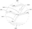
共同参阅图13及图14,图13是图11中局部区域XIII的结构示意图,图14是图11中第二支撑杆一实施例的结构示意图。Referring to FIG. 13 and FIG. 14 together, FIG. 13 is a schematic structural diagram of a partial area XIII in FIG. 11 , and FIG. 14 is a structural schematic diagram of an embodiment of the second support rod in FIG. 11 .

结合图14,第二支撑杆1421可以包括一体连接的承载部1422和收容部1423。其中,结合图13,中间滑块1412可以与承载部1422连接,第三支撑杆1431的一端可以与收容部1423背离中间滑块1412的一侧铰接,另一端则与另一第三支撑杆1431铰接。换言之,对于每一中间滑块1412、第二支撑杆1421和第三支撑杆1431而言,中间滑块1412和第三支撑杆1431可以分别位于第二支撑杆1421相背的两侧,以形成层叠结构,进而避免第一支撑组件141、第二支撑组件142和第三支撑组件143发生结构上的干涉。Referring to FIG. 14 , thesecond support rod 1421 may include abearing portion 1422 and a receivingportion 1423 that are integrally connected. 13, themiddle slider 1412 can be connected with thebearing portion 1422, one end of thethird support rod 1431 can be hinged with the side of the receivingportion 1423 away from themiddle slider 1412, and the other end is connected with anotherthird support rod 1431 Hinged. In other words, for each of themiddle slider 1412, thesecond support rod 1421 and thethird support rod 1431, themiddle slider 1412 and thethird support rod 1431 may be located on opposite sides of thesecond support rod 1421, respectively, to form Laminated structure, thereby avoiding the structural interference of thefirst support assembly 141 , thesecond support assembly 142 and thethird support assembly 143 .

进一步地,收容部1423背离中间滑块1412的一侧凹陷而与承载部1422之间形成一段差。其中,该段差在第三方向上的尺寸可以等于第三支撑杆1431在第三方向上的尺寸,以使得承载部1422背离中间滑块1412的一面能够与第三支撑杆1431背离中间滑块1412的一面共面,进而使得第二支撑杆1421与第三支撑杆1431能够共同支撑柔性显示模组11。Further, a side of theaccommodating portion 1423 facing away from themiddle slider 1412 is recessed to form a gap between the receivingportion 1423 and thebearing portion 1422 . The size of the step in the third direction may be equal to the size of thethird support rod 1431 in the third direction, so that the side of thebearing portion 1422 facing away from themiddle slider 1412 can be the same as the side of thethird support rod 1431 facing away from themiddle slider 1412 Coplanar, so that thesecond support rod 1421 and thethird support rod 1431 can jointly support theflexible display module 11 .

需要说明的是:第二支撑杆1421还可以包括位于收容部1423的孤岛部1424,孤岛部1424可以凸出于收容部1423而与承载部1422平齐。结合图12,孤岛部1424主要是用于兼顾第二支撑杆1421对柔性显示模组11的支撑与其对第三支撑杆1431的收容。It should be noted that thesecond support rod 1421 may further include anisland portion 1424 located in the receivingportion 1423 , and theisland portion 1424 may protrude from the receivingportion 1423 and be flush with thebearing portion 1422 . Referring to FIG. 12 , theisland portion 1424 is mainly used for both the support of theflexible display module 11 by thesecond support rod 1421 and the accommodation of thethird support rod 1431 .

以上所述仅为本申请的部分实施例,并非因此限制本申请的保护范围,凡是利用本申请说明书及附图内容所作的等效装置或等效流程变换,或直接或间接运用在其他相关的技术领域,均同理包括在本申请的专利保护范围内。The above descriptions are only part of the embodiments of the present application, and are not intended to limit the protection scope of the present application. Any equivalent device or equivalent process transformation made by using the contents of the description and drawings of the present application, or directly or indirectly applied to other related The technical field is similarly included in the scope of patent protection of this application.

Claims (21)

1. The supporting device applied to the flexible display module is characterized by comprising a shell assembly, a first supporting assembly and a second supporting assembly, wherein the shell assembly comprises a first shell and a second shell, one end of the first supporting assembly is connected with the first shell, the other end of the first supporting assembly is connected with the second shell and can be extended or shortened along a first direction, so that the second shell can be switched between an unfolded state and a folded state relative to the first shell, the second supporting assembly is connected with the first supporting assembly, and the second supporting assembly extends along a second direction which is crossed with the first direction; the supporting device is used for supporting the flexible display module in the unfolding state.
CN202011306951.3A2020-11-192020-11-19 Electronic equipment and supporting devices thereofActiveCN114519959B (en)

Priority Applications (1)

Application NumberPriority DateFiling DateTitle
CN202011306951.3ACN114519959B (en)2020-11-192020-11-19 Electronic equipment and supporting devices thereof

Applications Claiming Priority (1)

Application NumberPriority DateFiling DateTitle
CN202011306951.3ACN114519959B (en)2020-11-192020-11-19 Electronic equipment and supporting devices thereof

Publications (2)

Publication NumberPublication Date
CN114519959Atrue CN114519959A (en)2022-05-20
CN114519959B CN114519959B (en)2024-05-17

Family

ID=81594641

Family Applications (1)

Application NumberTitlePriority DateFiling Date
CN202011306951.3AActiveCN114519959B (en)2020-11-192020-11-19 Electronic equipment and supporting devices thereof

Country Status (1)

CountryLink
CN (1)CN114519959B (en)

Cited By (1)

* Cited by examiner, † Cited by third party
Publication numberPriority datePublication dateAssigneeTitle
CN115578933A (en)*2022-10-272023-01-06武汉天马微电子有限公司Flexible display device and electronic equipment

Citations (7)

* Cited by examiner, † Cited by third party
Publication numberPriority datePublication dateAssigneeTitle
KR20140014967A (en)*2012-07-272014-02-06한국과학기술원Flexible electronic device)
CN205028195U (en)*2015-07-172016-02-10广州奥翼电子科技有限公司Flexible display device
CN106601131A (en)*2016-12-282017-04-26上海天马微电子有限公司Flexible display device
CN210181960U (en)*2019-06-062020-03-24深圳市柔宇科技有限公司Flexible display device and electronic equipment
CN111383539A (en)*2020-04-272020-07-07武汉华星光电半导体显示技术有限公司Flexible display screen and display device
CN111819615A (en)*2018-02-092020-10-23深圳市柔宇科技股份有限公司 flexible display device
CN111833748A (en)*2020-07-132020-10-27Oppo广东移动通信有限公司 Flexible display device and electronic equipment

Patent Citations (7)

* Cited by examiner, † Cited by third party
Publication numberPriority datePublication dateAssigneeTitle
KR20140014967A (en)*2012-07-272014-02-06한국과학기술원Flexible electronic device)
CN205028195U (en)*2015-07-172016-02-10广州奥翼电子科技有限公司Flexible display device
CN106601131A (en)*2016-12-282017-04-26上海天马微电子有限公司Flexible display device
CN111819615A (en)*2018-02-092020-10-23深圳市柔宇科技股份有限公司 flexible display device
CN210181960U (en)*2019-06-062020-03-24深圳市柔宇科技有限公司Flexible display device and electronic equipment
CN111383539A (en)*2020-04-272020-07-07武汉华星光电半导体显示技术有限公司Flexible display screen and display device
CN111833748A (en)*2020-07-132020-10-27Oppo广东移动通信有限公司 Flexible display device and electronic equipment

Cited By (1)

* Cited by examiner, † Cited by third party
Publication numberPriority datePublication dateAssigneeTitle
CN115578933A (en)*2022-10-272023-01-06武汉天马微电子有限公司Flexible display device and electronic equipment

Also Published As

Publication numberPublication date
CN114519959B (en)2024-05-17

Similar Documents

PublicationPublication DateTitle
KR102063283B1 (en) Foldable Mechanism and Mobile Terminal of Mobile Terminal
CN111819615B (en) flexible display device
CN110580860B (en)Folding display device
CN113411422B (en) Support mechanisms and electronics
TWI493517B (en) Folding display device
JP2019506651A (en) Foldable components and mobile devices
WO2020057032A1 (en)Foldable support device and foldable flexible display device
CN113163042B (en)Electronic device
CN110010007A (en)Flexible display device and display equipment
CN112082059B (en)Supporting structural part and display device
CN109285459A (en)Foldable display panel's backup pad and foldable display device
US9746884B2 (en)Stretchable display device
CN113482161B (en) A foldable and expandable structure based on a rectangular six-fold origami unit
CA2476802A1 (en)Folded longitudinal torsional hinge for gimbaled mems mirror hinge
WO2021258613A1 (en)Display device
JP2003052163A5 (en)
CN114519959A (en)Electronic equipment and supporting device thereof
CN113411423B (en)Electronic equipment
CN112150931A (en)Supporting structural part and display device
CN113132516A (en)Electronic device
CN109587302A (en)Folding mobile terminal screen sliding assembly and mobile terminal
CN117703912B (en)Hinge mechanism, folding device and foldable electronic equipment
CN110738929A (en)multi-screen splicing and routing method and device and electronic equipment
CN115331559B (en)Flexible display device
CN115225742A (en)Electronic device

Legal Events

DateCodeTitleDescription
PB01Publication
PB01Publication
SE01Entry into force of request for substantive examination
GR01Patent grant
GR01Patent grant

[8]ページ先頭

©2009-2025 Movatter.jp