CN114516348B - Device and method for detecting limit of train freight vehicle - Google Patents
Device and method for detecting limit of train freight vehicleDownload PDFInfo
- Publication number
- CN114516348B CN114516348BCN202210240840.XACN202210240840ACN114516348BCN 114516348 BCN114516348 BCN 114516348BCN 202210240840 ACN202210240840 ACN 202210240840ACN 114516348 BCN114516348 BCN 114516348B
- Authority
- CN
- China
- Prior art keywords
- train
- sensor
- vehicle
- image scanning
- scanning device
- Prior art date
- Legal status (The legal status is an assumption and is not a legal conclusion. Google has not performed a legal analysis and makes no representation as to the accuracy of the status listed.)
- Active
Links
- 238000000034methodMethods0.000titleclaimsabstractdescription31
- 230000008569processEffects0.000claimsabstractdescription13
- 238000001514detection methodMethods0.000claimsdescription48
- 230000007246mechanismEffects0.000claimsdescription19
- 238000010586diagramMethods0.000description6
- 238000007689inspectionMethods0.000description3
- 230000004048modificationEffects0.000description2
- 238000012986modificationMethods0.000description2
- 238000004458analytical methodMethods0.000description1
- 238000004364calculation methodMethods0.000description1
- 238000005516engineering processMethods0.000description1
- 230000006872improvementEffects0.000description1
Images


Classifications
- B—PERFORMING OPERATIONS; TRANSPORTING
- B61—RAILWAYS
- B61K—AUXILIARY EQUIPMENT SPECIALLY ADAPTED FOR RAILWAYS, NOT OTHERWISE PROVIDED FOR
- B61K9/00—Railway vehicle profile gauges; Detecting or indicating overheating of components; Apparatus on locomotives or cars to indicate bad track sections; General design of track recording vehicles
- B61K9/02—Profile gauges, e.g. loading gauges
Landscapes
- Engineering & Computer Science (AREA)
- Mechanical Engineering (AREA)
- Length Measuring Devices By Optical Means (AREA)
- Train Traffic Observation, Control, And Security (AREA)
Abstract
Translated fromChinese
Description
Translated fromChinese技术领域technical field
本发明涉及铁路运输领域,具体涉及一种火车货运车辆限界检测装置及方法。The invention relates to the field of railway transportation, in particular to a device and method for detecting the limit of train freight vehicles.
背景技术Background technique
随着科技和铁路运输快速发展,采用铁路运输超长超宽货物的数量越来越多,超长超宽货物装车后,需要检测其装车后的整车宽度和高度,然后根据检测的数值进行评判车载货物是否超限,以保证本列车和正线上列车的安全运营。现有的火车超限检测装置一般都是装在火车正线上或者关键咽喉处,不能在火车发车前检测出货场超限与否,并且在正线上发现火车超限需要扣车进行整改,这种非常规货场装车后没有进行超限检测的列车,发车后给正线上的火车安全运营造成安全隐患。With the rapid development of science and technology and railway transportation, more and more ultra-long and ultra-wide goods are transported by railway. The numerical value is used to judge whether the on-board cargo exceeds the limit, so as to ensure the safe operation of the train and the train on the main line. Existing train overrun detection devices are generally installed on the main line of the train or at key throats, which cannot detect whether the freight yard is overrun before the train departs, and if the train overrun is found on the main line, the train needs to be impounded for rectification , This kind of unconventional freight yard has not been inspected for exceeding the limit after loading, and it will cause safety hazards to the safe operation of trains on the main line after departure.
发明内容Contents of the invention
有鉴于此,本发明的目的在于提出一种火车货运车辆限界检测装置及方法,减少车辆在运输过程中的安全隐患,提高车辆及货物的运输安全。In view of this, the object of the present invention is to provide a device and method for detecting the limit of train freight vehicles, which can reduce the potential safety hazards of vehicles during transportation and improve the transportation safety of vehicles and goods.
第一方面,本发明实施例提供一种火车货运车辆限界检测装置,所述火车货运车辆限界检测装置包括:支架;支撑柱,立设于所述支架上,所述支撑柱上设有导轨;第一传感器,设于所述支撑柱上,用于检测与所述火车货运车辆之间的距离;图像扫描装置,设于所述支撑柱的所述导轨上,所述图像扫描装置被设置为受控沿所述导轨运动,并用于扫描所述火车货运车辆获取车辆图像;第二传感器,设于所述图像扫描装置上,并用于检测所述图像扫描装置与地面之间的距离;以及控制单元,与所述第一传感器、所述图像扫描装置和所述第二传感器电连接,所述控制单元被设置为获取及处理所述第一传感器、所述图像扫描装置和所述第二传感器的采集信息。In a first aspect, an embodiment of the present invention provides a limit detection device for train freight vehicles. The limit detection device for train freight vehicles includes: a bracket; a support column erected on the support column, and a guide rail is provided on the support column; The first sensor is arranged on the support column and is used to detect the distance from the train freight vehicle; the image scanning device is arranged on the guide rail of the support column, and the image scanning device is configured to It is controlled to move along the guide rail, and is used to scan the train freight vehicle to obtain vehicle images; the second sensor is arranged on the image scanning device, and is used to detect the distance between the image scanning device and the ground; and control a unit electrically connected to the first sensor, the image scanning device and the second sensor, the control unit being configured to acquire and process the first sensor, the image scanning device and the second sensor collection information.
在一些实施例中,所述火车货运车辆限界检测装置还包括:多个定位块,位于所述火车货运车辆的两侧,多个所述定位块沿与所述火车货运车辆相平行的方向间隔排布;所述支架被设置为分别在各所述定位块上通过所述第一传感器、所述图像扫描装置和所述第二传感器获取所述火车货运车辆的局部限界信息,所述控制单元被设置为根据所述火车货运车辆的局部限界信息整合得到所述火车货运车辆的整车限界信息。In some embodiments, the train freight vehicle limit detection device further includes: a plurality of positioning blocks, located on both sides of the train freight vehicle, a plurality of the positioning blocks are spaced along a direction parallel to the train freight vehicle Arrangement; the bracket is set to obtain the local boundary information of the train freight vehicle through the first sensor, the image scanning device and the second sensor respectively on each of the positioning blocks, and the control unit It is configured to obtain the vehicle boundary information of the railway freight vehicle by integrating the local boundary information of the railway freight vehicle.
在一些实施例中,所述火车货运车辆限界检测装置还包括:走行滑轨,位于所述火车货运车辆的一侧且沿与所述火车货运车辆相平行的方向延伸;所述支架上还设有走行机构,所述支架被设置为通过所述走行机构沿所述走行滑轨运动。In some embodiments, the device for detecting the limit of the freight train vehicle further includes: a running slide rail, located on one side of the freight train vehicle and extending in a direction parallel to the freight train vehicle; There is a running mechanism, and the support is configured to move along the running slide rail through the running mechanism.
在一些实施例中,所述走行滑轨上间隔设置有多个定位块。In some embodiments, a plurality of positioning blocks are arranged at intervals on the traveling slide rail.
在一些实施例中,所述支架内活动设置有定位支杆;所述定位支杆被设置为受控自所述支架的表面伸出并固定于所述定位块上。In some embodiments, a positioning strut is movably arranged in the bracket; the positioning strut is configured to protrude from the surface of the bracket under control and be fixed on the positioning block.
在一些实施例中,所述走行滑轨的底面活动设置有至少两个第一支撑件,所述走行滑轨被设置为通过调整每个所述第一支撑件的支撑高度从而调整所述走行滑轨与水平面之间的角度;所述支架上还设有第三传感器,所述第三传感器用于检测所述支撑柱的倾角和仰角。In some embodiments, at least two first supports are movably provided on the bottom surface of the running slide, and the running slide is configured to adjust the walking height by adjusting the support height of each of the first supports. The angle between the slide rail and the horizontal plane; a third sensor is also provided on the support, and the third sensor is used to detect the inclination angle and the elevation angle of the support column.
在一些实施例中,所述支架的底面活动设置有至少两个第二支撑件,所述支架被设置为通过调整每个所述第二支撑件的支撑高度从而调整所述支架与水平面之间的角度;所述支架上还设有第三传感器,所述第三传感器用于检测所述支撑柱的倾角和仰角。In some embodiments, at least two second supports are movably provided on the bottom surface of the support, and the support is configured to adjust the distance between the support and the horizontal plane by adjusting the support height of each second support. angle; the support is also provided with a third sensor, the third sensor is used to detect the angle of inclination and elevation of the support column.
在一些实施例中,所述支架上还设有回转机构,所述支撑柱的一端通过所述回转机构呈转动设置于所述支架上,所述导轨位于所述支撑柱的另一端,所述图像扫描装置还被设置为跟随所述支撑柱同步转动并在预定角度范围内扫描所述火车货运车辆。In some embodiments, the bracket is further provided with a turning mechanism, one end of the supporting column is rotatably arranged on the bracket through the turning mechanism, the guide rail is located at the other end of the supporting column, and the The image scanning device is also configured to rotate synchronously with the support column and scan the train freight vehicle within a predetermined angle range.
在一些实施例中,所述火车货运车辆限界检测装置还包括基点标定装置;所述基点标定装置包括:走行小车,活动设置在所述火车货运车辆的轨道上;全站仪,设置在所述走行小车上,且所述全站仪位于所述火车货运车辆的轨道的中心线上;多个棱镜,分别设置在各所述定位块上;所述走行小车被设置为受控沿所述火车货运车辆的轨道运动,所述全站仪被设置为跟随所述走行小车同步运动,并检测各所述棱镜与所述全站仪之间的距离。In some embodiments, the train freight vehicle limit detection device also includes a base point calibration device; the base point calibration device includes: a traveling trolley, which is movable on the track of the train freight vehicle; a total station, which is set on the on the walking trolley, and the total station is located on the center line of the track of the train freight vehicle; a plurality of prisms are respectively arranged on each of the positioning blocks; the walking trolley is set to be controlled to move along the train The track movement of the freight vehicle, the total station is set to follow the moving trolley to move synchronously, and detect the distance between each of the prisms and the total station.
第二方面,本发明实施例提供一种火车货运车辆限界检测装置方法,所述方法包括:在所述火车货运车辆的一侧确定多个基点;通过火车货运车辆限界检测装置分别在每个所述基点测量所述车辆的局部限界信息;控制单元整合所述局部限界信息得到所述火车货运车辆的整车限界信息;控制单元根据所述整车限界信息分析及计算得到所述火车货运车辆的限界值;其中,所述火车货运车辆限界检测装置包括:支架;支撑柱,立设于所述支架上,所述支撑柱上设有导轨;第一传感器,设于所述支撑柱上,用于检测与所述火车货运车辆之间的距离;图像扫描装置,设于所述支撑柱的所述导轨上,所述图像扫描装置被设置为受控沿所述导轨运动,并用于扫描所述火车货运车辆获取车辆图像;第二传感器,设于所述图像扫描装置上,并用于检测所述图像扫描装置与地面之间的距离;以及控制单元,与所述第一传感器、所述图像扫描装置和所述第二传感器电连接,所述控制单元被设置为获取及处理所述第一传感器、所述图像扫描装置和所述第二传感器的采集信息。In the second aspect, an embodiment of the present invention provides a method for a detection device for the limit of a freight train vehicle, the method comprising: determining a plurality of base points on one side of the freight train vehicle; The base point measures the local boundary information of the vehicle; the control unit integrates the local boundary information to obtain the vehicle boundary information of the train freight vehicle; the control unit analyzes and calculates the vehicle boundary information of the train freight vehicle according to the vehicle boundary information. Limit value; wherein, the train freight vehicle limit detection device includes: a bracket; a support column, which is erected on the support, and a guide rail is provided on the support column; a first sensor is located on the support column, used To detect the distance between the train freight vehicle; the image scanning device is arranged on the guide rail of the support column, the image scanning device is set to move along the guide rail under control, and is used to scan the The train freight vehicle obtains the vehicle image; the second sensor is arranged on the image scanning device and is used to detect the distance between the image scanning device and the ground; and the control unit is connected with the first sensor and the image scanning device. The device is electrically connected to the second sensor, and the control unit is configured to acquire and process information collected by the first sensor, the image scanning device and the second sensor.
本发明实施例的火车货运车辆限界检测装置及方法可以通过第一传感器、第二传感器以及图像处理装置检测车辆的限界值,尤其是可以在货物装车完成后及运输作业前对车辆的限界值进行检测,避免了在运输过程中发现车辆限界值不符合标准而扣车的可能,且可以减少车辆在运输过程中的其他潜在风险,提高车辆及货物的运输安全。The train freight vehicle limit detection device and method of the embodiment of the present invention can detect the limit value of the vehicle through the first sensor, the second sensor and the image processing device, especially the limit value of the vehicle after the loading of the goods is completed and before the transportation operation. The inspection avoids the possibility of detaining the vehicle if the limit value of the vehicle does not meet the standards during the transportation process, and can reduce other potential risks of the vehicle during the transportation process and improve the transportation safety of the vehicle and goods.
附图说明Description of drawings
通过以下参照附图对本发明实施例的描述,本发明的上述以及其它目的、特征和优点将更为清楚,在附图中:Through the following description of the embodiments of the present invention with reference to the accompanying drawings, the above and other objects, features and advantages of the present invention will be more clear, in the accompanying drawings:
图1是本发明实施例的火车货运车辆限界检测装置的结构示意图;Fig. 1 is a schematic structural view of a train freight vehicle limit detection device according to an embodiment of the present invention;
图2是本发明实施例的火车货运车辆限界检测装置的支架部分的半剖图;Fig. 2 is a half-sectional view of the bracket part of the train freight vehicle limit detection device according to the embodiment of the present invention;
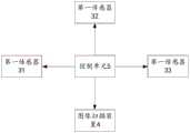
图3是本发明实施例的火车货运车辆限界检测装置的控制示意图;Fig. 3 is a control schematic diagram of a train freight vehicle limit detection device according to an embodiment of the present invention;
图4-图6是本发明实施例的火车货运车辆限界检测装置与火车的示意图;Fig. 4-Fig. 6 are the schematic diagrams of the limit detection device and the train of the train freight vehicle according to the embodiment of the present invention;
图7是本发明实施例的火车货运车辆限界检测装置的走行滑轨的示意图;Fig. 7 is a schematic diagram of the running slide rail of the train freight vehicle limit detection device according to the embodiment of the present invention;
图8是本发明实施例的火车货运车辆限界检测装置在不同点位测量火车的位置示意图;Fig. 8 is a schematic diagram of the position of the train freight vehicle limit detection device at different points to measure the train according to the embodiment of the present invention;
图9和图10是本发明实施例的基点标定装置的示意图;Fig. 9 and Fig. 10 are the schematic diagrams of the base point calibration device of the embodiment of the present invention;
图11是本发明实施例的一种火车货运车辆限界检测方法的流程示意图。Fig. 11 is a schematic flow chart of a method for detecting the limit of train freight vehicles according to an embodiment of the present invention.
具体实施方式Detailed ways
以下基于实施例对本发明进行描述,但是本发明并不仅仅限于这些实施例。在下文对本发明的细节描述中,详尽描述了一些特定的细节部分。对本领域技术人员来说没有这些细节部分的描述也可以完全理解本发明。为了避免混淆本发明的实质,公知的方法、过程、流程、元件和电路并没有详细叙述。The present invention is described below based on examples, but the present invention is not limited to these examples. In the following detailed description of the invention, some specific details are set forth in detail. The present invention can be fully understood by those skilled in the art without the description of these detailed parts. In order not to obscure the essence of the present invention, well-known methods, procedures, procedures, components and circuits have not been described in detail.
此外,本领域普通技术人员应当理解,在此提供的附图都是为了说明的目的,并且附图不一定是按比例绘制的。Additionally, those of ordinary skill in the art will appreciate that the drawings provided herein are for illustrative purposes and are not necessarily drawn to scale.
除非上下文明确要求,否则在说明书的“包括”、“包含”等类似词语应当解释为包含的含义而不是排他或穷举的含义;也就是说,是“包括但不限于”的含义。Unless the context clearly requires, the words "including", "including" and similar words in the description should be interpreted as inclusive rather than exclusive or exhaustive; that is, "including but not limited to".
在本发明的描述中,需要理解的是,术语“第一”、“第二”等仅用于描述目的,而不能理解为指示或暗示相对重要性。此外,在本发明的描述中,除非另有说明,“多个”的含义是两个或两个以上。In the description of the present invention, it should be understood that the terms "first", "second" and so on are used for descriptive purposes only, and cannot be interpreted as indicating or implying relative importance. In addition, in the description of the present invention, unless otherwise specified, "plurality" means two or more.
图1-图3为本发明实施例的火车货运车辆限界检测装置的示意图。如图1-图3所示,所述火车货运车辆限界检测装置包括支架1、支撑柱2、第一传感器31、第二传感器32、图像处理装置4和控制单元5。支撑柱2立设于支架1上,支撑柱2上设有导轨21。第一传感器31设于支撑柱2上并用于检测与所述火车货运车辆之间的距离。图像扫描装置4设于支撑柱2的导轨21上,图像扫描装置被设置为受控沿导轨21运动,并用于扫描所述火车货运车辆获取车辆图像。第二传感器32设于图像扫描装置4上,并用于检测图像扫描装置4与地面之间的距离。控制单元5与第一传感器31、图像扫描装置4和第二传感器32电连接,控制单元5被设置为获取及处理第一传感器31、图像扫描装置4和第二传感器32的采集信息。1-3 are schematic diagrams of a train freight vehicle limit detection device according to an embodiment of the present invention. As shown in FIG. 1-FIG. 3 , the train and freight vehicle limit detection device includes a
如图4-图6所示,本实施例的火车货运车辆限界检测装置8可以用于检测火车9的限界值,火车9可以是包括火车以及火车上的车载货物。其中,根据中华人民共和国国家标准GB146.1-2020《标准轨距铁路限界第1部分:火车货运车辆限界》,火车货运车辆限界指的是与线路中心垂直的、限制火车货运车辆外形尺寸的极限横断面轮廓,以及,车辆的高度和宽度应满足一定要求,以避免超高超宽货物运输带来的安全隐患。As shown in FIGS. 4-6 , the train freight vehicle
在本实施例中,第一传感器31朝向火车9设置,并可以检测其与火车9之间的距离。图像扫描装置4朝向火车9设置,并可以采集火车9的图像。第二传感器32朝向地面设置,并可以检测图像扫描装置4与地面之间的距离。图像扫描装置4的采集范围在图中以虚线示出,可以通过沿火车9的停靠方向移动支架1、以及沿导轨21移动图像扫描装置4来使得图像扫描装置4可以采集火车9的完整的侧面三维信息,通过将火车货运车辆限界检测装置8分别在火车9的两侧进行采集(可以是人为移动),来获得火车9的完整的整车三维信息。控制单元5可以获取所述三维信息并结合第一传感器31、第二传感器32检测到的宽度、高度信息构建火车9的三维模型(或者根据基准点位置坐标,反算出整车三维点云数值,并与现货限界值相比较,判断是否超限),并可以通过计算及分析得出火车9的限界值,从而确定火车9的限界值是否合格。本实施例可以在火车9装载货物后、运输开始前,对火车9的限界值进行检测,若发现问题及时调整,避免运输过程中发现火车9超载超限再整改带来的诸多问题,有效提高了铁路货运的安全性。In this embodiment, the
如图6和图7所示,本实施例还包括定位底座61和走行滑轨62,走行滑轨62位于火车9的一侧且沿与火车9相平行的方向延伸,定位块61设于走行滑轨62上,且定位块61具有多个,多个定位块61两两相隔一定间距地排布在走行滑轨62上。支架1上还设有走行机构11,走行机构11可以是多个轮、履带或是其他可供支架1移动的机构,支架1被设置为通过走行机构11沿走行滑轨62移动,并分别在各定位块61上通过第一传感器31、图像扫描装置4和第二传感器32获取火车9的局部限界信息。其中,多个定位块61两两之间的间距,可以是根据图像扫描装置4的采集宽度而定,使得支架1在所有定位块61上通过图像扫描装置4采集火车9的局部限界信息后,所有的局部限界信息可以整合成完整的火车9的限界信息。可选地,在火车9的一侧设有5个定位块61(或者更多定位块),且两个相邻的定位块61之间的间距是4米(或者3m、2m等)。控制单元5被配置为根据火车9的局部限界信息整合得到火车9的整车限界信息。As shown in Figures 6 and 7, this embodiment also includes a
应理解的是,在一些其他的可选实施例中,可以通过单独设置走行滑轨62供支架1移动的方式,或者是通过单独设置定位块61供支架1在多个点位采集火车9图像信息的方式来完成对火车9的限界检测,本实施例对此不作限制。It should be understood that, in some other optional embodiments, the
如图1和图2所示,在一些实施例中,走行滑轨62的底面活动设置有至少两个第一支撑件621,第一支撑件621可以是高度螺栓,走行滑轨62被设置为通过调整每个第一支撑件621的支撑高度从而调整走行滑轨62与水平面之间的角度。走行滑轨62的铺设面可能存在凹凸不平的情况,造成走行滑轨62与水平面之间存在角度,至少两个第一支撑件621分别设置在走行滑轨62的不同位置,通过调整每个第一支撑件621使走行滑轨62与水平面平行,以确保支架1沿着走行滑轨62移动时是水平移动。As shown in Figures 1 and 2, in some embodiments, at least two
由火车9的一端至另一端,沿着走行滑轨62移动支架1使得图像扫描装置4采集火车9一侧的侧面三维信息(或者三维点云数据),然后在火车9的另一侧以同样的方式采集另一侧的侧面三维信息(或者三维点云数据),并以第一传感器31的检测值为宽度值(或者与基准点数值相比较),以第二传感器32的检测值为高度值,可以确定火车9的限界值。From one end of the
优选地,支架1上设有第三传感器33,第三传感器33可以是陀螺仪,用于检测支撑柱2的倾角和仰角,在移动支架1的过程中,可以通过第三传感器33实时检测支撑柱2的倾斜情况来作为检测结果的补偿,以提高检测结果的精度,从而避免在移动支架1的过程中不小心导致支撑柱2发生晃动、倾斜、转动等的情况而影响检测精度。Preferably, the
如图2和图8所示,在一些实施例中,支架1内活动设置有定位支杆12,定位支杆12被设置为受控自支架1的表面伸出并固定于定位块61上。例如,定位块61上可以具有与定位支杆12对应的定位孔(未图示),当支架1移动到定位块61上时,定位块61对齐定位支杆12,定位支杆12可以向下伸出支架1的底面并与定位块61固定。支架1的底面还活动设置有至少两个第二支撑件13,支架1被设置为通过调整每个第二支撑件13的支撑高度从而调整支架1与水平面之间的角度,与第一支撑件621相类似,应通过调整第二支撑件13确保支架1与水平面相平行。支架1上还设有回转机构14,支撑柱2的一端通过回转机构14呈转动设置于支架1上,导轨21位于支撑柱2的另一端,图像扫描装置4还被设置为跟随支撑柱2同步转动并在预定角度范围内扫描火车9。其中,图8示出了多个火车货运车辆限界检测装置8,仅是为了示意火车货运车辆限界检测装置8的位置,在实际情况中,可以是通过移动单独一个火车货运车辆限界检测装置8至不同位置来检测火车9。As shown in FIG. 2 and FIG. 8 , in some embodiments, a
如图2所示,可选的,支架1的定位支杆12上可以活动设置有插销121,通过插销121插入或伸出定位支杆12来锁定定位支杆12。支撑柱12与回转机构14之间可以通过螺纹活动连接,回转机构14上可以具有锁紧手柄(未标示),通过转动所述锁紧手柄调整支撑柱12与回转机构14的螺纹锁紧程度,使得支撑柱12可以在一定范围内转动。As shown in FIG. 2 , optionally, a
可选的,第一传感器31、第二传感器32为激光测距传感器,图像扫描装置4为3D激光扫描仪或激光雷达。Optionally, the
如图9所示,本实施例还包括基点标定装置7,基点标定装置7包括走行小车71、全站仪72、多个棱镜73。走行小车71可以具有两个,并分别设置在火车9的轨道上,两个走行小车71之间可以通过横梁(未标示)连接,全站仪72设置在两走行小车71之间的横梁上,且全站仪72位于横梁的中心,也即轨道的中心线上。多个棱镜73分别设置在各定位块61上。走行小车71可以沿轨道运动,通过全站仪72检测棱镜73与全站仪72之间的距离和位置关系,通过调节定位块61的位置,使棱镜73与火车9轨道的中心线垂直距离一致,保证通过定位块61基点定位检测时,火车货运车辆限界检测装置距离轨道中心线的距离相等。As shown in FIG. 9 , this embodiment also includes a base point calibration device 7 , which includes a traveling
本发明实施例的火车货运车辆限界检测装置可以通过第一传感器、第二传感器以及图像处理装置检测车辆的限界值,尤其是可以在货物装车完成后及运输作业前对车辆的限界值进行检测,避免了在运输过程中发现车辆限界值不符合标准而扣车的可能,且可以减少车辆在运输过程中的其他潜在风险,提高车辆及货物的运输安全。The limit detection device for train freight vehicles in the embodiment of the present invention can detect the limit value of the vehicle through the first sensor, the second sensor and the image processing device, especially after the loading of the goods is completed and before the transportation operation, the limit value of the vehicle can be detected. , avoiding the possibility of detaining the vehicle if the threshold value of the vehicle does not meet the standard during transportation, and can reduce other potential risks of the vehicle during transportation, and improve the transportation safety of vehicles and goods.
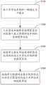
如图11所示,是本发明实施例的一种火车货运车辆限界检测方法的流程示意图,所述方法包括:As shown in FIG. 11 , it is a schematic flow chart of a method for detecting the limit of a train freight vehicle according to an embodiment of the present invention. The method includes:
S100:在所述火车货运车辆的一侧确定多个基点;S100: Determine a plurality of base points on one side of the train freight vehicle;
S200:通过火车货运车辆限界检测装置分别在每个基点测量所述车辆的局部限界信息;S200: Measure the local boundary information of the vehicle at each base point by using the boundary detection device for train freight vehicles;
S300:控制单元整合所述局部限界信息得到所述火车货运车辆的整车限界信息;S300: The control unit integrates the local boundary information to obtain the vehicle boundary information of the train freight vehicle;
S400:控制单元根据所述整车限界信息分析及计算得到所述火车货运车辆的限界值。S400: The control unit analyzes and calculates the limit value of the train freight vehicle according to the vehicle limit information.
其中,可以通过上述实施例中的火车货运车辆限界检测装置实施本方法。Wherein, the method may be implemented by the train and freight vehicle limit detection device in the above-mentioned embodiments.
具体地,在S100中,可以在基点上设置定位块61,每一个基点对应一个定位块61。同时,基点的位置可以是通过基点标定装置7来进行标定及校正。Specifically, in S100 , positioning blocks 61 may be set on the base points, and each base point corresponds to one
在S200中,支架1可以通过定位支杆12来与每一个定位块61固定或拆卸,以使得在每一个定位块61(即基点)的位置,第一传感器31、第二传感器32及图像采集装置4可以采集到车辆的各局部的限界信息,以便于在之后整合而成整车的限界信息。In S200, the
同时,火车货运车辆限界检测装置还可以包括走形机构11、回转机构14、第三传感器33等,其结构及功用已在上述第一实施例中进行介绍过,因此在本实施例中不再过多赘述。Simultaneously, the train and freight vehicle limit detection device can also include a
本实施例的方法可以基于火车货运车辆限界检测装置对车辆的限界值进行检测,减少火车货运车辆在运输过程中的安全隐患,提高火车货运车辆及货物的运输安全,尤其是可以在车辆装货后、出发前,进行检测,及时发现问题可以及时调整,提高作业效率。The method of this embodiment can detect the limit value of the vehicle based on the limit detection device of the train freight vehicle, reduce the potential safety hazards of the train freight vehicle during the transportation process, improve the transportation safety of the train freight vehicle and goods, and especially can load the vehicle After inspection and before departure, inspections are carried out, and problems can be found in time to be adjusted in time to improve operating efficiency.
以上所述仅为本发明的优选实施例,并不用于限制本发明,对于本领域技术人员而言,本发明可以有各种改动和变化。凡在本发明的精神和原理之内所作的任何修改、等同替换、改进等,均应包含在本发明的保护范围之内。The above descriptions are only preferred embodiments of the present invention, and are not intended to limit the present invention. For those skilled in the art, the present invention may have various modifications and changes. Any modification, equivalent replacement, improvement, etc. made within the spirit and principle of the present invention shall be included in the protection scope of the present invention.
Claims (10)
Priority Applications (1)
| Application Number | Priority Date | Filing Date | Title |
|---|---|---|---|
| CN202210240840.XACN114516348B (en) | 2022-03-10 | 2022-03-10 | Device and method for detecting limit of train freight vehicle |
Applications Claiming Priority (1)
| Application Number | Priority Date | Filing Date | Title |
|---|---|---|---|
| CN202210240840.XACN114516348B (en) | 2022-03-10 | 2022-03-10 | Device and method for detecting limit of train freight vehicle |
Publications (2)
| Publication Number | Publication Date |
|---|---|
| CN114516348A CN114516348A (en) | 2022-05-20 |
| CN114516348Btrue CN114516348B (en) | 2023-05-12 |
Family
ID=81598163
Family Applications (1)
| Application Number | Title | Priority Date | Filing Date |
|---|---|---|---|
| CN202210240840.XAActiveCN114516348B (en) | 2022-03-10 | 2022-03-10 | Device and method for detecting limit of train freight vehicle |
Country Status (1)
| Country | Link |
|---|---|
| CN (1) | CN114516348B (en) |
Family Cites Families (6)
| Publication number | Priority date | Publication date | Assignee | Title |
|---|---|---|---|---|
| CN101922133B (en)* | 2010-08-12 | 2012-06-06 | 上海铁路局科学技术研究所 | Intelligent track detector for high-efficiency measurement of track parameters |
| CN104655049A (en)* | 2015-03-16 | 2015-05-27 | 中国兵器工业集团第二一四研究所苏州研发中心 | Portable goods limit measurement instrument |
| CN206255025U (en)* | 2016-10-17 | 2017-06-16 | 华电重工股份有限公司 | A kind of cargo train vehicle information acquisition system |
| KR101907606B1 (en)* | 2017-08-22 | 2018-10-12 | 화이트윙시스템(주) | Dock management system |
| CN211855212U (en)* | 2020-04-16 | 2020-11-03 | 辽宁金洋集团信息技术有限公司 | Metering system for acquiring net value of cargo capacity of vehicle |
| CN112432610A (en)* | 2020-12-01 | 2021-03-02 | 株洲中车特种装备科技有限公司 | Train clearance detection device and detection method |
- 2022
- 2022-03-10CNCN202210240840.XApatent/CN114516348B/enactiveActive
Also Published As
| Publication number | Publication date |
|---|---|
| CN114516348A (en) | 2022-05-20 |
Similar Documents
| Publication | Publication Date | Title |
|---|---|---|
| CN204479742U (en) | A kind of tunnel-liner detections of radar servicing unit and tunnel-liner detections of radar car | |
| US8180590B2 (en) | Railroad surveying and monitoring system | |
| CN100480627C (en) | Steel rail wearing integrative parameter vehicle-mounted dynamic measuring device and method | |
| US7428781B2 (en) | Method and apparatus for performing overhead crane rail alignment surveys | |
| CN111366082A (en) | Mobile contact rail detection device and application method thereof | |
| CN110749297A (en) | A mobile station limit measuring instrument and measuring method | |
| CN101580071B (en) | Railway locomotive and vehicle operating attitude measurement system | |
| FI80790C (en) | FOERFARANDE OCH ANORDNING FOER BESTAEMNING AV ETT SPAORS LAEGE. | |
| US20150124239A1 (en) | System and method for measuring the position of the contact wire of an overhead power line relative to a railway track | |
| CN107401979B (en) | Vehicle body vibration displacement compensation device and method for catenary detection | |
| CN105261025B (en) | A kind of line-scan digital camera quick high accuracy caliberating device of high ferro detecting system | |
| CN111536940A (en) | A tunnel over-under-excavation detection system and its detection method | |
| JP6445383B2 (en) | Trajectory inspection method and apparatus | |
| CN101666716A (en) | Railway locomotive running attitude measuring method | |
| CN104554342B (en) | Rail smooth degree detection means | |
| CN109668515A (en) | Detector for train wheel pair size dynamic detection system and detection method | |
| RU116862U1 (en) | DEVICE FOR DETERMINING SPATIAL PARAMETERS OF OBJECTS OF RAILWAY INFRASTRUCTURE | |
| CN207816198U (en) | Vehicle length measuring device and vehicle outer profile measuring system | |
| CN211060871U (en) | A mobile platform limit measuring instrument | |
| CN114516348B (en) | Device and method for detecting limit of train freight vehicle | |
| CN216954629U (en) | Railway engineering comprehensive detection device | |
| CN205373648U (en) | Contact net geometric parameters dynamic verification device based on triangulation | |
| CN105648862B (en) | Dynamic continuous detection method of track centerline coordinates | |
| CN103507832A (en) | Detection device for rail physical dimension | |
| CN207029202U (en) | A kind of left and right track pitch measuring |
Legal Events
| Date | Code | Title | Description |
|---|---|---|---|
| PB01 | Publication | ||
| PB01 | Publication | ||
| SE01 | Entry into force of request for substantive examination | ||
| SE01 | Entry into force of request for substantive examination | ||
| GR01 | Patent grant | ||
| GR01 | Patent grant |