CN114513996A - Periprosthetic plate system - Google Patents
Periprosthetic plate systemDownload PDFInfo
- Publication number
- CN114513996A CN114513996ACN202080068939.5ACN202080068939ACN114513996ACN 114513996 ACN114513996 ACN 114513996ACN 202080068939 ACN202080068939 ACN 202080068939ACN 114513996 ACN114513996 ACN 114513996A
- Authority
- CN
- China
- Prior art keywords
- periprosthetic
- variable angle
- openings
- plate
- bone
- Prior art date
- Legal status (The legal status is an assumption and is not a legal conclusion. Google has not performed a legal analysis and makes no representation as to the accuracy of the status listed.)
- Pending
Links
Images


Classifications
- A—HUMAN NECESSITIES
- A61—MEDICAL OR VETERINARY SCIENCE; HYGIENE
- A61B—DIAGNOSIS; SURGERY; IDENTIFICATION
- A61B17/00—Surgical instruments, devices or methods
- A61B17/56—Surgical instruments or methods for treatment of bones or joints; Devices specially adapted therefor
- A61B17/58—Surgical instruments or methods for treatment of bones or joints; Devices specially adapted therefor for osteosynthesis, e.g. bone plates, screws or setting implements
- A61B17/68—Internal fixation devices, including fasteners and spinal fixators, even if a part thereof projects from the skin
- A61B17/70—Spinal positioners or stabilisers, e.g. stabilisers comprising fluid filler in an implant
- A61B17/7059—Cortical plates
- A—HUMAN NECESSITIES
- A61—MEDICAL OR VETERINARY SCIENCE; HYGIENE
- A61B—DIAGNOSIS; SURGERY; IDENTIFICATION
- A61B17/00—Surgical instruments, devices or methods
- A61B17/56—Surgical instruments or methods for treatment of bones or joints; Devices specially adapted therefor
- A61B17/58—Surgical instruments or methods for treatment of bones or joints; Devices specially adapted therefor for osteosynthesis, e.g. bone plates, screws or setting implements
- A61B17/68—Internal fixation devices, including fasteners and spinal fixators, even if a part thereof projects from the skin
- A61B17/80—Cortical plates, i.e. bone plates; Instruments for holding or positioning cortical plates, or for compressing bones attached to cortical plates
- A61B17/8004—Cortical plates, i.e. bone plates; Instruments for holding or positioning cortical plates, or for compressing bones attached to cortical plates with means for distracting or compressing the bone or bones
- A61B17/8014—Cortical plates, i.e. bone plates; Instruments for holding or positioning cortical plates, or for compressing bones attached to cortical plates with means for distracting or compressing the bone or bones the extension or compression force being caused by interaction of the plate hole and the screws
- A—HUMAN NECESSITIES
- A61—MEDICAL OR VETERINARY SCIENCE; HYGIENE
- A61B—DIAGNOSIS; SURGERY; IDENTIFICATION
- A61B17/00—Surgical instruments, devices or methods
- A61B17/56—Surgical instruments or methods for treatment of bones or joints; Devices specially adapted therefor
- A61B17/58—Surgical instruments or methods for treatment of bones or joints; Devices specially adapted therefor for osteosynthesis, e.g. bone plates, screws or setting implements
- A61B17/68—Internal fixation devices, including fasteners and spinal fixators, even if a part thereof projects from the skin
- A61B17/74—Devices for the head or neck or trochanter of the femur
- A—HUMAN NECESSITIES
- A61—MEDICAL OR VETERINARY SCIENCE; HYGIENE
- A61B—DIAGNOSIS; SURGERY; IDENTIFICATION
- A61B17/00—Surgical instruments, devices or methods
- A61B17/56—Surgical instruments or methods for treatment of bones or joints; Devices specially adapted therefor
- A61B17/58—Surgical instruments or methods for treatment of bones or joints; Devices specially adapted therefor for osteosynthesis, e.g. bone plates, screws or setting implements
- A61B17/68—Internal fixation devices, including fasteners and spinal fixators, even if a part thereof projects from the skin
- A61B17/80—Cortical plates, i.e. bone plates; Instruments for holding or positioning cortical plates, or for compressing bones attached to cortical plates
- A61B17/8033—Cortical plates, i.e. bone plates; Instruments for holding or positioning cortical plates, or for compressing bones attached to cortical plates having indirect contact with screw heads, or having contact with screw heads maintained with the aid of additional components, e.g. nuts, wedges or head covers
- A61B17/8047—Cortical plates, i.e. bone plates; Instruments for holding or positioning cortical plates, or for compressing bones attached to cortical plates having indirect contact with screw heads, or having contact with screw heads maintained with the aid of additional components, e.g. nuts, wedges or head covers wherein the additional element surrounds the screw head in the plate hole
- A—HUMAN NECESSITIES
- A61—MEDICAL OR VETERINARY SCIENCE; HYGIENE
- A61B—DIAGNOSIS; SURGERY; IDENTIFICATION
- A61B17/00—Surgical instruments, devices or methods
- A61B17/56—Surgical instruments or methods for treatment of bones or joints; Devices specially adapted therefor
- A61B17/58—Surgical instruments or methods for treatment of bones or joints; Devices specially adapted therefor for osteosynthesis, e.g. bone plates, screws or setting implements
- A61B17/68—Internal fixation devices, including fasteners and spinal fixators, even if a part thereof projects from the skin
- A61B17/80—Cortical plates, i.e. bone plates; Instruments for holding or positioning cortical plates, or for compressing bones attached to cortical plates
- A61B17/8052—Cortical plates, i.e. bone plates; Instruments for holding or positioning cortical plates, or for compressing bones attached to cortical plates immobilised relative to screws by interlocking form of the heads and plate holes, e.g. conical or threaded
- A61B17/8057—Cortical plates, i.e. bone plates; Instruments for holding or positioning cortical plates, or for compressing bones attached to cortical plates immobilised relative to screws by interlocking form of the heads and plate holes, e.g. conical or threaded the interlocking form comprising a thread
Landscapes
- Health & Medical Sciences (AREA)
- Orthopedic Medicine & Surgery (AREA)
- Life Sciences & Earth Sciences (AREA)
- Surgery (AREA)
- Neurology (AREA)
- Heart & Thoracic Surgery (AREA)
- Engineering & Computer Science (AREA)
- Biomedical Technology (AREA)
- Nuclear Medicine, Radiotherapy & Molecular Imaging (AREA)
- Medical Informatics (AREA)
- Molecular Biology (AREA)
- Animal Behavior & Ethology (AREA)
- General Health & Medical Sciences (AREA)
- Public Health (AREA)
- Veterinary Medicine (AREA)
- Surgical Instruments (AREA)
Abstract
Translated fromChinese
Description
Translated fromChinese相关申请的交叉引用CROSS-REFERENCE TO RELATED APPLICATIONS
本申请是2019年10月29日提交的名称为“Periprosthetic Bone Plate Systems”的未决美国临时专利申请号62/927,478的非临时申请,并且请求享有其申请日的权益,该申请的全部内容通过引用并入本文中。This application is a non-provisional application for pending U.S. Provisional Patent Application No. 62/927,478, filed October 29, 2019, entitled "Periprosthetic Bone Plate Systems," and claims the benefit of its filing date, the entire contents of which are approved by Incorporated herein by reference.
技术领域technical field
本公开涉及用于联接到一个或多个患者的骨、骨部分、骨块等的骨科植入物,并且更具体地涉及用于便于稳定假体周围骨折的骨板系统。The present disclosure relates to orthopaedic implants for coupling to one or more patients' bones, bone parts, bone fragments, etc., and more particularly to bone plate systems for facilitating stabilization of periprosthetic fractures.
背景技术Background technique
骨折通常通过将骨科植入物或装置固定到一个或多个患者的骨、骨部分、骨块等(可互换地使用,而无意限制)来进行修复。例如,患者接受骨科膝关节假体、骨科髋关节假体、髓内(“IM”)钉等来修复患者骨中的一个或多个骨折的情况并不少见。Fractures are typically repaired by securing orthopaedic implants or devices to one or more of the patient's bones, bone parts, bone fragments, etc. (used interchangeably and without limitation). For example, it is not uncommon for a patient to receive an orthopaedic knee prosthesis, an orthopaedic hip prosthesis, an intramedullary ("IM") nail, or the like, to repair one or more fractures in the patient's bone.
有时,骨折可能发生在先前手术植入的骨科植入物或装置周围的区域中。例如,可能在手术植入程序期间发生骨折。然而,备选地,正如大多数情境下的情况一样,患者可能在最初的外科植入程序后数年发生假体周围骨折。在一些情况下,手术植入的骨科植入物可能会使患者的骨更容易后期发生骨折。Occasionally, a fracture can occur in the area around a previously surgically implanted orthopaedic implant or device. For example, a fracture may occur during a surgical implant procedure. Alternatively, however, as is the case in most scenarios, patients may develop periprosthetic fractures years after the initial surgical implantation procedure. In some cases, surgically placed orthopaedic implants may make a patient's bone more prone to fractures later in life.
无论原因如何,先前手术植入的骨科植入物周围的假体周围骨折都会带来独特的固定挑战。例如,先前手术植入的骨科装置或植入物可能干扰后续植入的骨科骨固定板的放置。Regardless of the cause, periprosthetic fractures around previously surgically placed orthopaedic implants present unique fixation challenges. For example, a previously surgically implanted orthopaedic device or implant may interfere with placement of a subsequently implanted orthopaedic bone fixation plate.
例如,在一个场景中,在先前的手术植入的髋关节置换假体附近或周围可能发生假体周围髋部骨折。随着髋关节置换假体的数量增加,与其相关的假体周围骨折的数量也随之增加。一旦在先前手术植入的髋关节置换假体周围区域中发生骨折,治疗就可能由于骨质疏松症、骨中缺陷以及先前手术植入的髋关节置换假体的存在而复杂化。例如,与先前手术植入的髋关节置换假体相关联的柄、杆、螺钉和骨水泥可能会阻塞患者的髓管,从而阻止后续骨折的髓内固定。此外,柄和杆还可能阻止螺钉通过髓管固定以将后续的骨板固定到患者的骨。因此,由于选择有限,假体周围骨折和用于治疗假体周围骨折的对应技术大体上更困难。For example, in one scenario, a periprosthetic hip fracture may occur near or around a previously surgically implanted hip replacement prosthesis. As the number of hip replacement prostheses increases, so does the number of periprosthetic fractures associated with them. Once a fracture has occurred in the area around the previously surgically implanted hip replacement prosthesis, treatment may be complicated by osteoporosis, defects in the bone, and the presence of the previously surgically implanted hip replacement prosthesis. For example, stems, rods, screws, and bone cement associated with a previously surgically implanted hip replacement prosthesis may obstruct the patient's medullary canal, preventing intramedullary fixation of subsequent fractures. In addition, the stem and rod may also prevent the fixation of screws through the medullary canal for subsequent plate fixation to the patient's bone. Therefore, periprosthetic fractures and corresponding techniques for treating periprosthetic fractures are generally more difficult due to limited options.
然而,假体周围骨折需要治疗。例如,不稳定的假体周围骨折可能需要手术稳定和/或植入物置换以恢复功能。手术稳定可包括植入骨固定板以固定骨折骨的邻近区段以便于愈合,这可以在有或没有植入物置换的情况下发生。However, periprosthetic fractures require treatment. For example, unstable periprosthetic fractures may require surgical stabilization and/or implant replacement to restore function. Surgical stabilization may include implantation of bone fixation plates to immobilize adjacent segments of fractured bone for healing, which may occur with or without implant replacement.
许多目前已知的骨固定板的设计并未考虑假体周围骨折,因此它们通常表现出一个或多个不足或缺点。本公开的提供正是考虑到这一点。Many of the currently known bone fixation plates are not designed with periprosthetic fractures in mind, and as such they often exhibit one or more deficiencies or shortcomings. The present disclosure is provided with this in mind.
发明内容SUMMARY OF THE INVENTION
提供本发明内容以用简化形式介绍一系列构思,这些构思将在下面的具体实施方式部分中进一步描述。此发明内容并非旨在识别要求保护的主题的关键特征或基本特征,也不旨在帮助确定要求保护的主题的范围。This Summary is provided to introduce a series of concepts in a simplified form that are further described below in the Detailed Description section. This Summary is not intended to identify key features or essential features of the claimed subject matter, nor is it intended to be an aid in determining the scope of the claimed subject matter.
本文公开了许多骨固定板(例如,假体周围骨板)。骨固定板布置和构造成用于假体周围骨折。例如,在一个实施例中,骨固定板可以是股骨近端板的形式,以用于例如髋关节置换假体周围的假体周围骨折。备选地,在一个实施例中,骨固定板可以是股骨远端板的形式,以用于例如膝关节置换假体周围的假体周围骨折。在另一个实施例中,骨固定板可以是假体周围环形板或假体周围钩形板的形式,以用于例如髋关节置换假体周围的假体周围骨折。在另一个实施例中,骨固定板可以是肱骨板的形式。在任一情况下,骨固定板都设计和构造成用于跨越患者的骨中的后续骨折进行固定,同时设计和构造成具有一个或多个特征以便于避开先前手术植入的骨科植入物。A number of bone fixation plates (eg, periprosthetic plates) are disclosed herein. The bone fixation plate is arranged and configured for periprosthetic fractures. For example, in one embodiment, the bone fixation plate may be in the form of a proximal femoral plate for use in periprosthetic fractures, eg, around hip replacement prostheses. Alternatively, in one embodiment, the bone fixation plate may be in the form of a distal femoral plate for use in periprosthetic fractures, eg, around a knee replacement prosthesis. In another embodiment, the bone fixation plate may be in the form of a periprosthetic annular plate or a periprosthetic hook plate for use in periprosthetic fractures, eg, around hip replacement prostheses. In another embodiment, the bone fixation plate may be in the form of a humerus plate. In either case, the bone fixation plate is designed and constructed for fixation across a subsequent fracture in the patient's bone, while being designed and constructed with one or more features to facilitate avoidance of a previously surgically implanted orthopaedic implant .
在一个实施例中,骨固定板(例如,假体周围骨板)可以包括头部部分、轴部分、上表面、下表面或面向骨的表面、中心纵向轴线和外周表面(例如,外周边表面)。轴部分包括多个螺纹锁定螺钉开口,所述多个螺纹锁定螺钉开口分别布置和构造成接收多个锁定螺钉。另外,轴部分可包括多个可变角度紧固件开口,所述多个可变角度紧固件开口分别布置和构造成接收多个可变角度螺钉。在一个实施例中,多个可变角度紧固件开口可以沿着轴部分的外周表面定位,而多个锁定螺钉开口可以居中定位(例如,定位成更靠近或基本上邻近轴部分的中心纵向轴线)。In one embodiment, a bone fixation plate (eg, a periprosthetic bone plate) may include a head portion, a shaft portion, an upper surface, a lower surface, or a bone-facing surface, a central longitudinal axis, and a peripheral surface (eg, an outer peripheral surface). ). The shaft portion includes a plurality of threaded locking screw openings respectively arranged and configured to receive a plurality of locking screws. Additionally, the shaft portion may include a plurality of variable angle fastener openings each arranged and configured to receive a plurality of variable angle screws. In one embodiment, the plurality of variable angle fastener openings may be positioned along the outer peripheral surface of the shaft portion, while the plurality of locking screw openings may be centrally positioned (eg, positioned closer to or substantially adjacent to the central longitudinal direction of the shaft portion) axis).
在一个实施例中,螺纹锁定螺钉开口可以大于可变角度紧固件开口,所述可变角度紧固件开口例如沿着轴部分的周边定位(例如,多个螺纹锁定螺钉开口包括第一直径,并且多个可变角度紧固件开口包括第二直径,第一直径大于第二直径)。例如,在一个实施例中,螺纹锁定螺钉开口的尺寸可设定成和构造成接收例如4.5mm锁定螺钉。可变角度紧固件开口的尺寸可设定成和构造成接收例如3.5mm骨螺钉。备选地,在一些实施例中,螺纹锁定螺钉开口和可变角度紧固件开口可以具有相同的尺寸。例如,在一些实施例中,螺纹锁定螺钉开口和可变角度紧固件开口的尺寸和构造可设定成接收例如3.5mm骨螺钉。In one embodiment, the threaded locking screw openings may be larger than the variable angle fastener openings located, for example, along the perimeter of the shaft portion (eg, the plurality of threaded locking screw openings include a first diameter , and the plurality of variable angle fastener openings include a second diameter, the first diameter being greater than the second diameter). For example, in one embodiment, the threaded locking screw opening may be sized and configured to receive, for example, a 4.5 mm locking screw. The variable angle fastener opening may be sized and configured to receive, for example, a 3.5 mm bone screw. Alternatively, in some embodiments, the threaded locking screw opening and the variable angle fastener opening may be the same size. For example, in some embodiments, the threaded locking screw openings and variable angle fastener openings may be sized and configured to receive, for example, 3.5 mm bone screws.
在各种实施例中,骨固定板的轴部分可包括第一区域和第二区域,第一区域邻近于骨固定板的头部部分定位。形成于第一区域中的多个可变角度紧固件开口布置和构造成使得第一可变角度紧固件开口和第二可变角度紧固件开口横向对准成一排。也就是说,第一区域可包括沿着轴部分的第一区域的周边横向对准的可变角度紧固件开口(例如,第一区域中的多个可变角度紧固件开口布置和构造成使得第一可变角度紧固件开口和第二可变角度紧固件开口彼此横向对准地定位在中心纵向轴线的任一侧上)。形成于第二区域中的多个可变角度紧固件开口是非横向对准的。也就是说,第二区域可包括非横向对准的可变角度紧固件开口。第二区域中的多个可变角度紧固件开口布置和构造成使得可变角度紧固件开口相对于彼此在两侧交替(例如,单个可变角度紧固件开口定位成一排,其中随着每排的可变角度紧固件开口在轴部分上向远侧移动,每排的可变角度紧固件开口在两侧交替)。如此布置,轴部分的第一区域包括更多数量的可变角度紧固件开口,以向外科医生提供更多选择来邻近骨固定板的头部部分放置可变角度骨紧固件。In various embodiments, the shaft portion of the bone fixation plate can include a first region and a second region, the first region being positioned adjacent to the head portion of the bone fixation plate. The plurality of variable angle fastener openings formed in the first region are arranged and configured such that the first variable angle fastener openings and the second variable angle fastener openings are aligned laterally in a row. That is, the first region may include variable angle fastener openings aligned laterally along the perimeter of the first region of the shaft portion (eg, a plurality of variable angle fastener openings in the first region arranged and configured such that the first variable angle fastener opening and the second variable angle fastener opening are positioned on either side of the central longitudinal axis in lateral alignment with each other). The plurality of variable angle fastener openings formed in the second region are non-laterally aligned. That is, the second region may include non-laterally aligned variable angle fastener openings. The plurality of variable angle fastener openings in the second region are arranged and configured such that the variable angle fastener openings alternate on both sides relative to each other (eg, individual variable angle fastener openings are positioned in a row, with As each row of variable angle fastener openings moves distally on the shaft portion, the variable angle fastener openings of each row alternate on both sides). So arranged, the first region of the shaft portion includes a greater number of variable angle fastener openings to provide the surgeon with more options for placing variable angle bone fasteners adjacent the head portion of the bone fixation plate.
在一个实施例中,骨固定板可包括形成于骨板的下表面中的多个底切。在各种实施例中,多个底切可分别与多个可变角度紧固件开口对准或重合。In one embodiment, the bone fixation plate may include a plurality of undercuts formed in the lower surface of the bone plate. In various embodiments, the plurality of undercuts may be aligned or coincident with the plurality of variable angle fastener openings, respectively.
在一个实施例中,骨固定板可包括头部部分和轴部分。头部部分可轮廓化以与患者的解剖结构(例如,如患者的骨节、转子等)相匹配。与头部部分相对的轴部分可以布置和构造成使得轴部分的端部部分能够轮廓化。也就是说,例如,与头部部分相对的轴部分的端部部分可以变薄(例如,具有从端部部分朝向头部部分延伸的减小的横截面积或渐缩的横截面积),以提高骨固定板的端部部分的轮廓性来匹配患者的解剖结构。In one embodiment, the bone fixation plate may include a head portion and a shaft portion. The head portion may be contoured to match the patient's anatomy (eg, such as the patient's condyles, trochanters, etc.). The shaft portion opposite the head portion may be arranged and configured such that an end portion of the shaft portion can be contoured. That is, for example, the end portion of the shaft portion opposite the head portion may be thinned (eg, having a reduced or tapered cross-sectional area extending from the end portion toward the head portion), Match the patient's anatomy with improved contouring of the end portion of the bone fixation plate.
在一个实施例中,端部部分可包括形成于其中的多个锁定螺钉开口,多个锁定螺钉开口形成于端部部分中,包括第一远侧锁定螺钉开口和第二远侧锁定螺钉开口,第一远侧锁定螺钉开口和第二远侧锁定螺钉开口中的每一个包括形成于骨板的下表面中的沉孔。在一个实施例中,轴部分进一步包括一个或多个克氏针开口,所述一个或多个克氏针开口布置和构造成使得克氏针能够穿过其中,一个或多个克氏针开口中的至少一个定位于第一远侧锁定螺钉开口与第二远侧锁定螺钉开口之间。在一个实施例中,与头部部分相对的轴部分的端部部分包括以阵列形成的多个可变角度紧固件开口。In one embodiment, the end portion may include a plurality of locking screw openings formed therein, a plurality of locking screw openings formed in the end portion including a first distal locking screw opening and a second distal locking screw opening, Each of the first distal locking screw opening and the second distal locking screw opening includes a counterbore formed in the lower surface of the bone plate. In one embodiment, the shaft portion further comprises one or more K-wire openings arranged and configured to enable the K-wires to pass therethrough, the one or more K-wire openings At least one of them is positioned between the first distal locking screw opening and the second distal locking screw opening. In one embodiment, the end portion of the shaft portion opposite the head portion includes a plurality of variable angle fastener openings formed in an array.
在一个实施例中,骨板选自股骨近端板、股骨远端板、假体周围环形板、假体周围钩形板和肱骨板中的一个。In one embodiment, the bone plate is selected from one of a proximal femoral plate, a distal femoral plate, a periprosthetic annular plate, a periprosthetic hook plate, and a humerus plate.
在一个实施例中,骨板的头部部分包括多个可变角度螺钉开口,并且没有任何锁定螺钉开口。In one embodiment, the head portion of the bone plate includes a plurality of variable angle screw openings and does not have any locking screw openings.
在一个实施例中,骨板的头部部分包括多个锁定螺钉开口,并且没有任何可变角度紧固件开口。In one embodiment, the head portion of the bone plate includes a plurality of locking screw openings and is devoid of any variable angle fastener openings.
在一个实施例中,头部部分包括多个锁定螺钉开口和多个可变角度紧固件开口,与多个锁定螺钉开口相比,多个锁定螺钉开口更居中定位。In one embodiment, the head portion includes a plurality of locking screw openings and a plurality of variable angle fastener openings, the plurality of locking screw openings being more centrally located than the plurality of locking screw openings.
在一个实施例中,形成于头部部分中的多个可变角度紧固件开口布置和构造成双排,使得可变角度紧固件开口定位成横向排,其中第一可变角度紧固件开口和第二可变角度紧固件开口定位在每一排中。In one embodiment, the plurality of variable angle fastener openings formed in the head portion are arranged and configured in double rows such that the variable angle fastener openings are positioned in transverse rows, wherein the first variable angle fasteners A piece opening and a second variable angle fastener opening are positioned in each row.
在一个实施例中,骨固定板可以是环形板的形式。也就是说,骨固定板可包括头部部分和轴部分,头部部分是布置和构造成邻近于患者转子定位的环的形式。在一个实施例中,环形头部部分可以与轴部分一体地形成。在一个实施例中,环形头部部分包括第一节段、与第一节段间隔开的第二节段,以及联接第一节段和第二节段的桥接节段,环形头部部分包括第一节段和第二节段与桥接节段之间的开口。在一个实施例中,桥接节段可包括居中定位在其上的多个可变角度紧固件开口。In one embodiment, the bone fixation plate may be in the form of an annular plate. That is, the bone fixation plate may include a head portion and a shaft portion, the head portion being in the form of a ring arranged and configured to be positioned adjacent to the patient's trochanter. In one embodiment, the annular head portion may be integrally formed with the shaft portion. In one embodiment, the annular head portion includes a first segment, a second segment spaced from the first segment, and a bridge segment coupling the first segment and the second segment, the annular head portion including Openings between the first and second segments and the bridging segment. In one embodiment, the bridge segment may include a plurality of variable angle fastener openings centrally positioned thereon.
另外和/或备选地,环形头部部分可包括分别布置和构造成接收多个锁定螺钉的多个螺纹锁定螺钉开口,以及分别布置和构造成接收多个可变角度紧固件的多个可变角度紧固件开口,多个可变角度紧固件开口围绕多个螺纹锁定螺钉开口分散。Additionally and/or alternatively, the annular head portion may include a plurality of threaded locking screw openings each arranged and configured to receive a plurality of locking screws, and a plurality of threaded locking screw openings each arranged and configured to receive a plurality of variable angle fasteners The variable angle fastener openings are dispersed around the plurality of threaded locking screw openings.
在一个实施例中,头部部分可包括布置和构造成用于接合患者的转子的第一钩形构件和第二钩形构件,第一钩形构件和第二钩形构件不对称,使得第一钩形构件不同于第二钩形构件。在一个实施例中,第一钩形构件和第二钩形构件具有不同尺寸、不同构造或其组合中的一者。In one embodiment, the head portion may include a first hook member and a second hook member arranged and configured to engage the patient's trochanter, the first hook member and the second hook member being asymmetrical such that the first hook member and the second hook member are asymmetrical. One hook member is different from the second hook member. In one embodiment, the first hook member and the second hook member have one of different sizes, different configurations, or a combination thereof.
在一个实施例中,公开了一种假体周围骨板。在一个实施例中,骨板包括头部部分、轴部分、上表面、下表面、中心纵向轴线和外周表面。轴部分进一步包括分别布置和构造成接收多个锁定螺钉的多个螺纹锁定螺钉开口,以及分别布置和构造成接收多个可变角度螺钉的多个可变角度紧固件开口;其中多个螺纹锁定螺钉开口包括第一直径,并且多个可变角度紧固件开口包括第二直径,第一直径大于第二直径。In one embodiment, a periprosthetic bone plate is disclosed. In one embodiment, the bone plate includes a head portion, a shaft portion, an upper surface, a lower surface, a central longitudinal axis, and a peripheral surface. The shaft portion further includes a plurality of threaded locking screw openings respectively arranged and configured to receive a plurality of locking screws, and a plurality of variable angle fastener openings respectively arranged and configured to receive a plurality of variable angle screws; wherein the plurality of threads The locking screw opening includes a first diameter, and the plurality of variable angle fastener openings include a second diameter, the first diameter being larger than the second diameter.
本公开的实施例提供了许多优点。例如,通过并入本公开的一个或多个特征,为外科医生提供了用于邻近先前手术植入的骨科装置或植入物跨越后续骨折来固定骨固定板的更多选择。另外,通过并入本公开的一个或多个特征,骨固定板布置和构造成允许跨越骨的主要长度设置板。如此布置,消除或至少最小化在板的端部处出现的应力梯级(例如,如本领域的普通技术人员将了解,增加的应力梯级在板的端部处出现,这引起骨上应力增加,这是假体周围骨折的一个促成因素。通过在骨(例如患者的股骨)的整个长度设置板,消除或至少大大最小化应力梯级)。Embodiments of the present disclosure provide many advantages. For example, by incorporating one or more features of the present disclosure, surgeons are provided with more options for securing bone fixation plates across subsequent fractures adjacent to a previously surgically implanted orthopaedic device or implant. Additionally, by incorporating one or more features of the present disclosure, the bone fixation plate is arranged and configured to allow placement of the plate across a major length of the bone. So arranged, the stress steps occurring at the ends of the plates are eliminated or at least minimized (eg, as those of ordinary skill in the art will appreciate, increased stress steps occur at the ends of the plates, which cause increased stress on the bone, This is a contributing factor to periprosthetic fractures. By placing the plate along the entire length of the bone (eg, the patient's femur), stress steps are eliminated or at least greatly minimized).
下文参考附图详细描述本发明的实施例中的至少一些的另外特征和优点,以及本发明的各种实施例的结构和操作。Additional features and advantages of at least some of the embodiments of the invention, as well as the structure and operation of various embodiments of the invention, are described in detail below with reference to the accompanying drawings.
附图说明Description of drawings
现在将参照附图中仅以举例的方式描述本公开的装置的具体实施例,在附图中:Specific embodiments of the apparatus of the present disclosure will now be described, by way of example only, with reference to the accompanying drawings, in which:
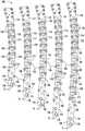
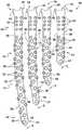
图1是根据本公开的各种长度的骨固定板的俯视图;1 is a top view of various lengths of bone fixation plates in accordance with the present disclosure;
图2是图1中所示的骨固定板的仰视图;Figure 2 is a bottom view of the bone fixation plate shown in Figure 1;
图3A是图1中所示的骨固定板的示例性实施例的顶部透视图;3A is a top perspective view of the exemplary embodiment of the bone fixation plate shown in FIG. 1;
图3B是图3A中所示的骨固定板的底部透视图;Figure 3B is a bottom perspective view of the bone fixation plate shown in Figure 3A;
图4是根据本公开的各种长度的骨固定板的俯视图;4 is a top view of various lengths of bone fixation plates in accordance with the present disclosure;
图5是图4中所示的骨固定板的仰视图;Figure 5 is a bottom view of the bone fixation plate shown in Figure 4;
图6A是图4中所示的骨固定板的示例性实施例的俯视图;6A is a top view of the exemplary embodiment of the bone fixation plate shown in FIG. 4;
图6B是图6A中所示的骨固定板的仰视图;Figure 6B is a bottom view of the bone fixation plate shown in Figure 6A;
图7是根据本公开的各种长度的骨固定板的俯视图;7 is a top view of various lengths of bone fixation plates in accordance with the present disclosure;
图8是图7中所示的骨固定板的仰视图;Figure 8 is a bottom view of the bone fixation plate shown in Figure 7;
图9是图7中所示的骨固定板的示例性实施例的顶部透视图;Figure 9 is a top perspective view of the exemplary embodiment of the bone fixation plate shown in Figure 7;
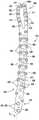
图10是根据本公开的骨固定板的示例性实施例的俯视图;10 is a top view of an exemplary embodiment of a bone fixation plate according to the present disclosure;
图11是图10中所示的骨固定板的仰视图;Figure 11 is a bottom view of the bone fixation plate shown in Figure 10;
图12是根据本公开的骨固定板的示例性实施例的俯视图;12 is a top view of an exemplary embodiment of a bone fixation plate according to the present disclosure;
图13是图12中所示的骨固定板的仰视图;Figure 13 is a bottom view of the bone fixation plate shown in Figure 12;
图14是根据本公开的各种长度的骨固定板的俯视图;14 is a top view of various lengths of bone fixation plates in accordance with the present disclosure;
图15是图14中所示的骨固定板的示例性实施例的仰视图;以及Figure 15 is a bottom view of the exemplary embodiment of the bone fixation plate shown in Figure 14; and
图16是图14中所示的骨固定板的示例性实施例的底部透视图。FIG. 16 is a bottom perspective view of the exemplary embodiment of the bone fixation plate shown in FIG. 14 .
应理解,所述附图不一定按比例绘制,并且所公开的实施例有时以示意图和局部视图的方式示出。在某些情况下,对于理解所公开的方法和器械并非必要或使其他详细信息难以理解的详细信息可能被省略。应进一步理解,本公开不限于本文示出的特定实施例。It should be understood that the drawings are not necessarily to scale and that the disclosed embodiments are sometimes shown in schematic and partial views. In some instances, details that are not necessary for an understanding of the disclosed methods and apparatus or that make other details difficult to understand may be omitted. It should be further understood that the present disclosure is not limited to the specific embodiments shown herein.
具体实施方式Detailed ways
下文将参照附图更全面地描述骨科骨固定板的各种特征、方面等,其中将示出和描述骨固定板的一个或多个方面或特征。应当了解,所述各种特征、方面或类似物可以独立使用,或相互结合使用。应当了解,如本文所公开的骨固定板可以以许多不同的形式体现并且不应解释为限于本文所阐述的实施例。更确切地说,提供这些实施例以便本公开将骨固定板的某些方面或特征传达给本领域技术人员。在附图中,除非另有说明,否则相同的数字指代相同的元件。Various features, aspects, etc. of the orthopaedic bone fixation plate will be described more fully below with reference to the accompanying drawings, in which one or more aspects or features of the bone fixation plate will be shown and described. It should be understood that the various features, aspects or the like can be used independently or in combination with each other. It should be appreciated that bone fixation plates as disclosed herein may be embodied in many different forms and should not be construed as limited to the embodiments set forth herein. Rather, these embodiments are provided so that this disclosure will convey certain aspects or features of bone fixation plates to those skilled in the art. In the drawings, the same numerals refer to the same elements unless otherwise indicated.
本文公开了骨固定板,所述骨固定板包括用于使得能够提高灵活性以用于将骨固定板邻近先前手术植入的骨科植入物联接到患者的骨、骨部分、骨块等(术语在本文中可互换使用,而无意限制)的一个或多个方面或特征。也就是说,如前文所述,并且本领域的普通技术人员将了解,每年有许多患者接受植入一个或多个骨科装置的外科手术。例如,膝关节置换、髋关节置换、IM钉植入等是常见的。有时,骨折可能发生在手术植入的骨科植入物或装置周围的区域中。这些骨折通常称为假体周围骨折,因为它们在先前的外科植入的骨科装置或植入物附近发生。Disclosed herein is a bone fixation plate comprising a bone, bone portion, bone fragment, etc. for enabling increased flexibility for coupling the bone fixation plate to a patient's bone adjacent to a previously surgically implanted orthopaedic implant ( The terms are used interchangeably herein and are not intended to limit one or more aspects or features of ). That is, as previously mentioned, and as will be appreciated by those of ordinary skill in the art, many patients each year undergo surgical procedures to implant one or more orthopaedic devices. For example, knee replacement, hip replacement, IM nail implantation, etc. are common. Sometimes a fracture can occur in the area around a surgically placed orthopaedic implant or device. These fractures are often referred to as periprosthetic fractures because they occur near a previously surgically implanted orthopaedic device or implant.
假体周围骨折带来了独特的固定挑战。例如,先前手术植入的骨科装置或植入物可能干扰骨固定板的放置和/或固定。例如,在一个场景中,先前手术植入的骨科装置或植入物的IM钉或柄部分可能干扰骨固定板的定位和/或用于将骨固定板固定到患者的骨的骨紧固件、螺钉等(术语在本文中可互换使用,而无意限制)的放置。另外,先前手术植入的骨科装置或植入物周围的患者的骨例如由于骨质疏松、骨中的缺陷等退化可能会使骨固定板在患者骨上的固定和定位进一步复杂化。因此,由于选择有限,假体周围骨折和用于治疗假体周围骨折的对应技术大体上更困难。Periprosthetic fractures present unique fixation challenges. For example, a previously surgically implanted orthopedic device or implant may interfere with placement and/or fixation of the bone fixation plate. For example, in one scenario, the IM nail or stem portion of a previously surgically implanted orthopedic device or implant may interfere with the positioning of the bone fixation plate and/or the bone fasteners used to secure the bone fixation plate to the patient's bone , screws, etc. (terms are used interchangeably herein and are not intended to be limiting). Additionally, previously surgically implanted orthopaedic devices or the patient's bone surrounding the implant may degenerate, eg, due to osteoporosis, defects in the bone, etc., which may further complicate the fixation and positioning of the bone fixation plate on the patient's bone. Therefore, periprosthetic fractures and corresponding techniques for treating periprosthetic fractures are generally more difficult due to limited options.
因而,如本文将描述,本公开公开了包括可组合或单独使用的一个或多个特征或方面的许多骨固定板(例如,假体周围骨板),这些特征设计和构造成提供提高的灵活性,使得外科医生能够邻近先前手术植入的骨科装置或植入物跨越患者骨中的骨折定位和固定骨固定板。Thus, as will be described herein, the present disclosure discloses a number of bone fixation plates (eg, periprosthetic bone plates) that include one or more features or aspects that may be used in combination or alone, and which features are designed and configured to provide increased flexibility The flexibility allows the surgeon to position and fix the bone fixation plate across the fracture in the patient's bone adjacent to a previously surgically implanted orthopaedic device or implant.
如本文将描述,骨固定板可以具有各种形状和/或构造。应当了解,骨固定板可以以任何合适的形状和/或构造提供,如本领域普通技术人员将了解的,其可以取决于固定的患者骨的位置和类型。例如,骨固定板可以包括符合骨的弓形表面。此外,骨固定板可以布置和构造成跨越、接触等股骨远端、股骨近端、胫骨远端、胫骨近端、肱骨近端、肱骨远端、腓骨、尺骨、桡骨、桡骨远端、足骨或手骨、长骨上的骨干骨折等。As will be described herein, bone fixation plates can have various shapes and/or configurations. It will be appreciated that the bone fixation plate may be provided in any suitable shape and/or configuration, which may depend on the location and type of patient's bone being fixed, as will be appreciated by one of ordinary skill in the art. For example, a bone fixation plate may include an arcuate surface that conforms to the bone. In addition, the bone fixation plate can be arranged and configured to span, contact, etc. the distal femur, proximal femur, distal tibia, proximal tibia, proximal humerus, distal humerus, fibula, ulna, radius, distal radius, foot bone Or diaphyseal fractures on hand bones, long bones, etc.
此外,骨固定板可以包括任何现在已知的或以后开发的附加特征,例如,一个或多个开口或槽,其设计成接收例如外科植入工具、不同的紧固件(例如,非锁定紧固件)等。Additionally, the bone fixation plate may include any additional features now known or later developed, eg, one or more openings or slots designed to receive eg surgical implant tools, various fasteners (eg, non-locking fasteners) firmware) etc.
骨固定板可以由现在已知或以后开发的任何合适的材料制造,包括例如金属、聚合物、塑料、陶瓷、可吸收的复合材料、不可吸收的复合材料等。合适的材料可以包括如钛、不锈钢、钴铬、聚醚醚酮(PEEK)、聚乙烯、超高分子量聚乙烯(UHMWPE)、可吸收的聚乳酸(PLA)、聚乙醇酸(PGA)、此类材料的组合或合金或任何其他适当的材料,这些材料具有足够的强度,可以固定到骨上并保持骨,同时具有足够的生物相容性,可以植入患者的身体。在一些实施例中,骨紧固件可以由与骨固定板相同的材料制成。在其它实施例中,紧固件可以由与骨固定板相比不同的材料制成。Bone fixation plates may be fabricated from any suitable material now known or later developed, including, for example, metals, polymers, plastics, ceramics, resorbable composites, non-resorbable composites, and the like. Suitable materials may include, for example, titanium, stainless steel, cobalt chromium, polyetheretherketone (PEEK), polyethylene, ultra-high molecular weight polyethylene (UHMWPE), absorbable polylactic acid (PLA), polyglycolic acid (PGA), the A combination or alloy of like materials or any other suitable material that is strong enough to fix to and retain bone while being biocompatible enough to be implanted in a patient's body. In some embodiments, the bone fastener may be made of the same material as the bone fixation plate. In other embodiments, the fasteners may be made of a different material than the bone fixation plate.
所述紧固件可以是现在已知或以后开发的任何类型的紧固件。例如,所述紧固件可以包括任何类型的外螺纹,包括标准或非标准螺纹。例如,外螺纹可以布置成连续的脊或非连续的脊。所述外螺纹可以形成一个回转的一部分,一个完整回转,多个回转,单导程,多导程,或本领域中已知的任何其他螺纹。附加地和/或备选地,在锁定螺钉的情况下,紧固件的头部部分可以包括将与形成在骨固定板中的锁定螺钉开口接合并且位于其内的任何表面。例如,头部部分可以包括螺纹。备选地,所述头部部分可以包括一系列的凹坑、脊、凸起、纹理区域或任何其他可以固定所述紧固件的表面。The fasteners may be of any type now known or later developed. For example, the fasteners may include any type of external thread, including standard or non-standard threads. For example, the external threads may be arranged as continuous ridges or non-continuous ridges. The external thread may form part of one revolution, one full revolution, multiple revolutions, single lead, multiple leads, or any other thread known in the art. Additionally and/or alternatively, in the case of locking screws, the head portion of the fastener may include any surface that will engage and be located within a locking screw opening formed in the bone fixation plate. For example, the head portion may include threads. Alternatively, the head portion may include a series of dimples, ridges, protrusions, textured areas, or any other surface to which the fastener may be secured.
紧固件可以是由现在已知或以后开发的任何适当材料制成的现在已知或以后开发的任何紧固件。紧固件可以包括用于接收驱动器的开孔,以便驱动紧固件穿过骨固定板并且进入患者的骨中。开孔可以是任何尺寸和形状,例如,其可以具有六边形构造以接收对应的六边形驱动器、十字螺丝头、平头、星形构造、Torx,或可以与驱动器协作以将紧固件驱动穿过骨固定板并且进入患者的骨中的任何其它适合的构造。The fasteners may be any now known or later developed fasteners made of any suitable material now known or later developed. The fasteners may include apertures for receiving drivers for driving the fasteners through the bone fixation plate and into the patient's bone. The aperture can be of any size and shape, for example, it can have a hexagonal configuration to receive a corresponding hexagonal driver, Phillips head, flat head, star configuration, Torx, or can cooperate with a driver to drive a fastener Any other suitable formation through the bone fixation plate and into the patient's bone.
所述紧固件的轴可以是全螺纹、部分螺纹或螺旋叶片,和/或可以包括一个或多个钉子、可展开的爪子、可扩展的元件,或允许所述轴与患者的骨啮合的任何特征。所述轴也有可以是无螺纹的,使得所述紧固件采取钉子或销子的形式。在某些手术中,例如,主要目标是防止骨段倾斜,或者不用担心所述紧固件从患者的骨中拉出,因而所述轴不需要有螺纹或以其他方式配置为与患者的骨啮合的手术中,这种替代实施方式可以是优选方式。所述轴的端部可以是一个自攻或自钻的尖端。The shaft of the fastener may be fully threaded, partially threaded, or helical blade, and/or may include one or more nails, expandable claws, expandable elements, or elements that allow the shaft to engage the patient's bone any characteristic. The shaft may also be unthreaded, so that the fasteners take the form of nails or pins. In certain procedures, for example, where the primary goal is to prevent tilting of the bone segment, or there is no concern about the fasteners pulling out of the patient's bone, the shaft need not be threaded or otherwise configured to engage the patient's bone. In meshing procedures, this alternative embodiment may be preferred. The end of the shaft may be a self-tapping or self-drilling tip.
在任何情况下,如从剩余公开内容将显而易见的,本公开的焦点在于骨固定板的示例性实施例,其包括布置和构造成提供提高的灵活性以用于邻近具有先前手术植入的骨科装置或植入物的区域定位和固定骨固定板的一个或多个特征或方面。因此,应当了解,本公开不应限于具有任何特定构造的骨固定板的任何特定构造,除非特别声明。In any event, as will be apparent from the remainder of the disclosure, the focus of the present disclosure is on exemplary embodiments of bone fixation plates that include arrangements and configurations to provide increased flexibility for use adjacent to orthopaedic implants with prior surgical implantation A region of a device or implant locates and fixes one or more features or aspects of a bone fixation plate. Accordingly, it should be understood that the present disclosure should not be limited to any particular configuration of bone fixation plates having any particular configuration, unless specifically stated.
假体周围股骨近端骨固定板Periprosthetic proximal femoral bone fixation plate
参考图1-3B,公开了用于修复患者骨中的骨折的具有各种长度的骨固定板100的各种实施例。如本文将描述的,骨固定板100可以是股骨近端板的形式。也就是说,骨固定板100布置和构造成邻近于患者的股骨近端定位。另外,如本文将描述,骨固定板100包括一个或多个特征,使得骨固定板100便于定位和固定到患者的股骨近端,所述股骨近端先前植入有手术骨科植入物或装置,如例如IM钉、髋关节假体等。因而,骨固定板100布置和构造用于假体周围骨折,并且因此可称为假体周围骨固定板或假体周围股骨近端骨固定板。1-3B, various embodiments of
如图所示,假体周围股骨近端骨固定板100可包括下侧、下表面或面向骨的表面102(术语在本文中可互换使用,而无意限制)和上表面104。另外,假体周围股骨近端骨固定板100包括头部部分110和轴部分115。此外,假体周围股骨近端骨固定板100包括形成于其中的多个开口120,以用于接收多个紧固件(未示出),来用于将假体周围股骨近端骨固定板100联接到患者的骨。As shown, the periprosthetic proximal femoral
如本文将描述,根据本公开的一个方面或特征,开口120可以是锁定螺钉(或紧固件)开口122或可变角度开口或可变角度紧固件(或螺钉)开口124(术语在本文中可互换使用,而无意限制)的形式。也就是说,如本领域的普通技术人员将了解,锁定螺钉开口122可包括形成于其内表面上的多个螺纹,以用于与形成于骨紧固件的头部部分的外表面上的螺纹匹配。如此布置,骨紧固件可以说是经由锁定螺钉开口122锁定到假体周围股骨近端骨固定板100。也就是说,如本领域的普通技术人员将了解,骨紧固件旋拧穿过形成于假体周围股骨近端骨固定板100中的锁定螺钉开口122中的一个并且进入患者的骨中。骨紧固件经由形成在骨紧固件的头部部分上的螺纹固定到假体周围股骨近端骨固定板100,所述螺纹与形成在假体周围股骨近端骨固定板100中的螺纹锁定螺钉开口122协作。这相对于患者的骨固定了假体周围股骨近端骨固定板100,并且提供了在假体周围股骨近端骨固定板100与骨紧固件之间的刚性固定。也就是说,由于骨紧固件的头部部分与形成在假体周围股骨近端骨固定板100的锁定螺钉开口122中的螺纹相互交叉,故板100和紧固件形成了稳定的系统或构造,并且骨折的稳定性可以依赖于或借助于结构的刚度。将骨紧固件锁定到假体周围股骨近端骨固定板100中可以实现角向和轴向稳定性,并且消除骨紧固件拨动、滑动或移位的可能性,从而降低术后复位损失的风险。As will be described herein, according to one aspect or feature of the present disclosure, the
如前文所述,假体周围股骨近端骨固定板100还包括形成于其中的多个可变角度开口124,以用于接收非锁定或可变角度(例如,多轴)骨紧固件。在使用中,可变角度开口124布置和构造成使得插入其中的骨紧固件能够实现比例如螺纹地联接到假体周围股骨近端骨固定板100的常规锁定螺钉更大的插入角度范围。例如,在一个实施例中,骨紧固件的角位置可以旋转通过大约±15度的范围,但是可允许的多轴旋转范围可以变化,包括大于和小于十五度。在使用中,可变角度开口124可以现在已知或以后开发的任何合适方式、构造等提供,以使得骨紧固件能够相对于假体周围股骨近端骨固定板100多轴定位或成角度。As previously described, the periprosthetic proximal femoral
如图所示,在一个实施例中,可变角度开口124可包括翅片或突出部,其从可变角度开口124的内表面径向向内延伸并且进入可变角度开口124的内部区域,并且其构造成与骨紧固件的头部部分接合或协作。在使用中,翅片接合骨紧固件的头部部分以便将骨紧固件以期望位置和期望角度定向固定在可变角度开口124内。关于翅片的操作和构造的更多信息可以在最早的申请日期是2005年7月25日,现在是美国专利号10,092,337的名称为“Systems and Methods for Using Polyaxial Plates”的美国专利申请号15/706,877;2012年6月15日提交的名称为“Variable Angle Locking Implant”的美国专利申请号13/524,506,以及2020年6月2日提交的名称为“Orthopedic Implant with ImprovedVariable Angle Locking Mechanism”的国际PCT专利申请号PCT/US20/35729中找到,其全部内容以引用方式并入本文中。As shown, in one embodiment, the variable angle opening 124 may include fins or protrusions that extend radially inward from the inner surface of the variable angle opening 124 and into the interior region of the variable angle opening 124, And it is configured to engage or cooperate with the head portion of the bone fastener. In use, the fins engage the head portion of the bone fastener to secure the bone fastener within the variable angle opening 124 in a desired position and a desired angular orientation. More information on the operation and construction of fins can be found in US Patent Application No. 15/ entitled "Systems and Methods for Using Polyaxial Plates", dated July 25, 2005, now US Patent No. 10,092,337 706,877; U.S. Patent Application No. 13/524,506, filed June 15, 2012, entitled "Variable Angle Locking Implant," and International PCT, entitled "Orthopedic Implant with Improved Variable Angle Locking Mechanism," filed June 2, 2020 Found in Patent Application No. PCT/US20/35729, the entire contents of which are incorporated herein by reference.
根据本公开的一个方面,锁定螺钉开口122可以布置和构造成相对于可变角度开口124接收较大直径的骨紧固件。也就是说,例如,锁定螺钉开口122可以布置和构造成接收4.5mm骨紧固件,而可变角度开口124可以布置和构造成接收3.5mm骨紧固件,但是这些尺寸仅仅是示例性的,并且设想了其它尺寸的骨紧固件。通过布置和构造假体周围股骨近端骨固定板100以接收较大直径的锁定螺钉,假体周围股骨近端骨固定板100能够更好地固定到患者的骨。同时,通过并入较小的可变角度开口124,假体周围股骨近端骨固定板100能够更好地便于非锁定螺钉(例如,多轴可变角度骨螺钉)围绕先前手术植入的骨科装置或植入物的定位(例如,较小的非锁定骨紧固件使外科医生能够更好地导航先前手术植入的骨科装置或植入物)。According to one aspect of the present disclosure, the locking
附加地和/或备选地,根据本公开的另一方面或特征,锁定螺钉开口122可以定位在假体周围股骨近端骨固定板100的轴部分115内。例如,在假体周围股骨近端骨固定板100的一个实施例中,如图所示,假体周围股骨近端骨固定板100的头部部分110可以完全没有任何锁定螺钉开口122,但是可以设想,头部部分110可以包括一个或多个锁定螺钉开口122。此外,如图所示,与形成于轴部分115中的可变角度开口124相比,锁定螺钉开口122可以更居中定位。例如,在一个实施例中,轴部分115可包括中心纵向轴线CL,锁定螺钉开口122可基本上沿着假体周围股骨近端骨固定板100的轴部分115的中心纵向轴线CL定位,而形成于轴部分115中的可变角度开口124(如图所示)可以沿着和/或邻近于假体周围股骨近端骨固定板100的轴部分115的外周或表面106定位。也就是说,锁定螺钉开口122定位成相对于可变角度开口124更靠内,更靠近轴部分115的中心纵向轴线CL,可变角度开口定位成更靠近轴部分115的外周或周边表面106。Additionally and/or alternatively, according to another aspect or feature of the present disclosure, the locking
由此布置,通过沿着和/或邻近轴部分115的外周106定位可变角度开口124,假体周围股骨近端骨固定板100能够更好地定位可变角度骨紧固件,以避开先前手术植入的骨科装置或植入物(例如,外科医生能够更好地定位和插入一个或多个骨紧固件穿过形成于假体周围股骨近端骨固定板100中的可变角度开口124,同时例如避开患者的股骨近端中的先前手术植入的骨科装置或植入物的柄部分或IM钉)。With this arrangement, by positioning the variable angle opening 124 along and/or adjacent the
附加地和/或备选地,根据本公开的另一方面或特征,假体周围股骨近端骨固定板100的轴部分115可包括第一区域116和第二区域118。如图所示,第一区域116可以邻近于假体周围股骨近端骨固定板100的头部部分110定位。在一个或多个实施例中,可变角度开口124可以布置和构造成使得它们在轴部分115的第一区域116内彼此横向定位。也就是说,如图所示,可变角度开口124可视为定位成横向排,其中两个可变角度开口124定位成一排,沿着假体周围股骨近端骨固定板100的每一侧或周边表面106各一个。如此布置,轴部分115的第一区域116中的可变角度开口124可以称为定位成双排。同时,如图所示,形成于假体周围股骨近端骨固定板100的轴部分115的第二区域118中的可变角度开口124可以布置成使得它们相对于彼此交替。也就是说,如图所示,可变角度开口124可视为定位成横向排,其中仅单个可变角度开口124定位成一排,其中可变角度开口124在假体周围股骨近端骨固定板100的其与之邻近定位的那一侧或周边表面106交替。如此布置,如图所示,轴部分115的第一区域116可包括与轴部分115的第二区域118相比更多(例如,两倍数目的)可变角度开口124,即使轴部分115的第一区域116和第二区域118可具有相同数目的可变角度开口124的排,但可设想第一区域116和第二区域118也可以具有不同排数。通过将可变角度开口124在轴部分115的第一区116中定位成双排,当将可变角度的骨紧固件在先前手术植入的骨科装置或植入物的柄部分或IM钉的预期附近插入患者的骨中时,向外科医生提供了更多选择。同时,通过在轴部分115的第二区域118中仅提供单排交替的可变角度开口124,更好地维持骨固定板100的强度。Additionally and/or alternatively, in accordance with another aspect or feature of the present disclosure, the
参考图2和3B,假体周围股骨近端骨固定板100的轴部分115可包括形成于下侧或面向骨的表面102中的多个底切或凹槽130。然而,附加地和/或备选地,根据本公开的另一方面或特征,多个底切130可以与形成于假体周围股骨近端骨固定板100的轴部分115中的可变角度开口124重合或共置。也就是说,形成于轴部分115中的可变角度开口124可以定位在或驻留于形成于面向骨的表面102中的底切130内。在使用中,底切130的大小可设定和构造成提供间隙,以使线缆在股骨近端骨固定板100下方通过。在一个实施例中,多个底切130与形成在假体周围股骨近端骨固定板100的轴部分115中的可变角度开口124共置以提供增加的骨板强度(例如,底切130和可变角度开口124位于中心锁定螺钉开口122之间的中心,这是峰值应力的位置。如果底切130或可变角度开口124定位成更靠近中心锁定螺钉开口122之一,则板的整体强度将减小)。Referring to FIGS. 2 and 3B , the
附加地和/或备选地,根据本公开的另一方面或特征,假体周围股骨近端骨固定板100的远端部分119(例如,与头部部分110相对的端部部分)可包括变薄。也就是说,远端部分119可包括减小或渐缩的横截面积,以便于远端部分119相对于患者的解剖结构的轮廓化。一般来说,如本领域的普通技术人员将了解,在使用期间,外科医生通常选择大小设定成和构造成桥接或跨越骨折的整个区域的具有一定长度的骨固定板。例如,骨固定板从股骨踝或患者的转子或更高部延伸和/或延伸到股骨踝或转子或更高部并不少见。在使用中,骨固定板的头部部分可以是高度轮廓化的以匹配患者的解剖结构。然而,提供具有轮廓化的两端的骨固定板产生许多问题。例如,一般来说,提供在两端进行解剖结构约束或轮廓化的骨固定板将不如预期适合个别患者。因此,解除对骨板的一端的解剖结构约束以使骨板能够轮廓化以为每个个别患者提供更好的贴合是有益的。附加地和/或备选地,提供具有轮廓化的两端的骨固定板产生许多制造问题。根据本公开的一个方面或特征,远端部分119(例如,与头部部分110相对的端部部分)可包括减小的横截面积,以更好地使外科医生能够使远端部分119轮廓化以适应患者的解剖结构。Additionally and/or alternatively, in accordance with another aspect or feature of the present disclosure, the distal end portion 119 (eg, the end portion opposite the head portion 110 ) of the periprosthetic proximal femoral
参考图3B,根据本公开的另一方面,形成于轴部分115的远端部分119中的锁定螺钉开口122可包括形成于其下侧或面向骨的表面102中的下侧沉孔126。例如,如图所示,形成于股骨近端骨固定板的轴部分115中的两个最远侧锁定螺钉开口122可包括下侧沉孔126,但可设想更多或更少的锁定螺钉开口可以在下侧或面向骨的表面102上开沉孔。在使用中,通过在形成于板100的远端部分119中的锁定螺钉开口122的下侧或面向骨的表面102中提供沉孔126,下侧沉孔锁定螺钉开口126可以与器械组合使用以抓住和压缩骨折处。3B, according to another aspect of the present disclosure, the locking screw opening 122 formed in the
股骨近端骨固定板100的轴部分115还可包括用于使克氏针能够穿过其中的多个克氏针开口128。如图所示,附加地和/或备选地,根据本公开的另一方面或特征,初始克氏针开口128可以定位在最远侧的两个锁定螺钉开口122之间。另外,轴部分115可包括形成于其中的多个附加克氏针开口128。在使用中,多个克氏针开口128允许外科医生在他们已使骨折复位之后将骨固定板100暂时保持到患者的骨。The
如大体所示,并且如本领域的普通技术人员将了解,取决于板的长度,底切、可变角度开口、锁定螺钉开口等的数目将在各种骨固定板之间变化。As generally shown, and as one of ordinary skill in the art will appreciate, the number of undercuts, variable angle openings, locking screw openings, etc. will vary between various bone fixation plates depending on the length of the plate.
假体周围股骨远端骨固定板Periprosthetic distal femoral bone fixation plate
参考图4-6B,公开了用于修复患者骨中的骨折的具有各种长度的备选骨固定板200的各种实施例。如本文将描述,结合图4-6B示出和描述的骨固定板200可以基本上类似于上文结合图1-3B描述的假体周围股骨近端骨固定板100,然而骨固定板200可以是股骨远端板的形式。也就是说,骨固定板200布置和构造成邻近于患者的股骨远端定位。另外,如本文将描述,骨固定板200包括一个或多个特征,使得骨固定板200便于定位和固定到患者的股骨远端,所述股骨远端先前接收了手术植入的骨科装置或植入物,如IM钉、膝关节假体等。因而,骨固定板200布置和构造用于假体周围骨折,并且因此可称为假体周围骨固定板或假体周围股骨远端骨固定板。4-6B, various embodiments of alternative
如图所示,假体周围股骨远端骨固定板200可包括下侧、下或面向骨的表面202和上表面204。另外,假体周围股骨远端骨固定板200包括头部部分210和轴部分215。此外,假体周围股骨远端骨固定板200包括形成于其中的多个开口220,以用于接收多个紧固件(未示出)来用于将假体周围股骨远端骨固定板200联接到患者的骨。As shown, the periprosthetic distal femoral
如先前结合股骨近端骨固定板100描述的,假体周围股骨远端骨固定板200可包括多个锁定螺钉开口222和多个可变角度开口224。类似于结合股骨近端骨固定板100描述的锁定螺钉开口222和可变角度开口224,并且根据本公开的一个方面,形成于假体周围股骨远端骨固定板200中的锁定螺钉开口222可布置和构造成相对于形成于假体周围股骨远端骨固定板200中的可变角度开口224接收较大直径的骨紧固件。也就是说,例如,锁定螺钉开口222可以布置和构造成接收4.5mm骨紧固件,而可变角度开口224可以布置和构造成接收3.5mm骨紧固件,但是这些尺寸仅仅是示例性的,并且设想了其它尺寸的骨紧固件。通过布置和构造假体周围股骨远端骨固定板200以接收较大直径的锁定螺钉,假体周围股骨远端骨固定板200能够更好地固定到患者的骨。同时,通过并入较小的可变角度开口224,假体周围股骨远端骨固定板200能够更好地便于非锁定螺钉(例如,多轴可变角度骨螺钉)围绕先前手术植入的骨科装置或植入物的定位。As previously described in connection with the proximal femoral
附加地和/或备选地,根据本公开的另一方面或特征并且如前文所述,锁定螺钉开口222可以定位在假体周围股骨远端骨固定板200的轴部分215内。如图所示,与形成于轴部分215中的可变角度开口224相比,锁定螺钉开口222可以更居中定位。如图所示,可变角度开口224可以沿着和/或邻近假体周围股骨远端骨固定板200的轴部分215的外周或表面206定位。例如,在一个实施例中,轴部分215可包括中心纵向轴线CL,锁定螺钉开口222可基本上沿着假体周围股骨近端骨固定板200的轴部分215的中心纵向轴线CL定位,而可变角度开口224可以沿着和/或邻近于假体周围股骨远端骨固定板200的轴部分215的外周或表面206定位。也就是说,锁定螺钉开口222定位成相对于可变角度开口224更靠内,更靠近轴部分215的中心纵向轴线CL,可变角度开口定位成更靠近轴部分215的外周或周边表面206。Additionally and/or alternatively, in accordance with another aspect or feature of the present disclosure and as previously described, the locking
由此布置,通过沿着和/或邻近轴部分215的外周206定位可变角度开口224,假体周围股骨远端骨固定板200能够更好地定位可变角度骨紧固件,以避开先前手术植入的骨科装置或植入物(例如,外科医生能够更好地定位和插入一个或多个骨紧固件穿过形成于假体周围股骨远端骨固定板200中的可变角度开口224,同时例如避开患者的股骨远端中的先前手术植入的骨科装置或植入物的膝关节假体的柄部分或IM钉)。With this arrangement, by positioning the variable angle opening 224 along and/or adjacent the
如图所示,在一个实施例中,结合假体周围股骨远端骨固定板200,假体周围股骨远端骨固定板200的头部部分210可包括多个锁定螺钉开口222。在一个实施例中,头部部分210还可以包括一个或多个较大直径的可变角度孔224a(例如,布置和构造成接收4.5mm骨紧固件)。备选地,假体周围股骨远端骨固定板200的头部部分210可以完全没有任何可变角度开口224(例如,假体周围股骨远端骨固定板200的头部部分215可以只包括锁定螺钉开口222)。备选地,可设想假体周围股骨远端骨固定板200的头部部分210可包括一个或多个较小直径的可变角度开口224(布置和构造成接收3.5mm骨紧固件)。As shown, in one embodiment, in conjunction with the periprosthetic distal femoral
另外,如结合假体周围股骨远端骨固定板200所示,假体周围股骨远端骨固定板200的轴部分215可以只包括单排交替可变角度开口224(例如,轴部分215可以没有如先前描述的任何双排可变角度开口224)。然而,尽管未示出,但可以设想,假体周围股骨远端骨固定板100的轴部分215可包括类似于假体周围股骨近端骨固定板100的第一区域和第二区域,其中在第一区域中,可变角度开口彼此横向定位/对准,并且在第二区域中,可变角度开口可以交替地定位,使得与第二区域相比,轴部分的第一区域包括更多可变角度开口,由此在将骨紧固件在先前手术植入的骨科装置或植入物的预期附近插入患者的骨中时,向外科医生提供了更多选择。Additionally, as shown in conjunction with the periprosthetic distal femoral
参考图5和6B,假体周围股骨远端骨固定板200的轴部分215可包括形成于下侧或面向骨的表面202中的多个底切或凹槽230。然而,附加地和/或备选地,根据本公开的另一方面或特征,多个底切230可以与形成于假体周围股骨远端骨固定板200的轴部分215中的可变角度开口224重合或共置。也就是说,形成于轴部分215中的可变角度开口224可以定位在或驻留于形成于面向骨的表面202中的底切230内。在使用中,底切230的大小可设定成和构造成提供间隙,以使线缆在股骨远端骨固定板100下方通过。如前文所述,在一个实施例中,多个底切230与形成在假体周围股骨远端骨固定板200的轴部分215中的可变角度开口224共置以提供增加的骨板强度(例如,底切230和可变角度开口224在中心锁定螺钉开口222之间居中,这是峰值应力的位置。如果底切230或可变角度开口224定位成更靠近中心锁定螺钉开口222中的一个,则板的整体强度将减小)。5 and 6B, the
附加地和/或备选地,根据本公开的另一方面或特征,并且如先前结合假体周围股骨近端骨固定板100描述的,假体周围股骨远端骨固定板200的端部部分219(例如,与假体周围股骨远端骨固定板200的头部部分210相对的近端部分219)可以包括变薄。也就是说,轴部分215的端部部分219可以包括减小或渐缩的横截面积,以便于端部部分相对于患者的解剖结构的轮廓化。也就是说,如前文所述,根据本公开的一个方面或特征,轴部分215的端部部分219(例如,与头部部分210相对的端部部分219)可包括减小的横截面积,以更好地使外科医生能够使端部部分219轮廓化以适应患者的解剖结构。例如,如前文所述,提供具有轮廓化的两端的骨固定板产生许多问题。例如,一般来说,提供在两端进行解剖结构约束或轮廓化的骨固定板将不如预期适合个别患者。因此,解除对骨板的一端的解剖结构约束以使骨板能够轮廓化以为每个个别患者提供更好的贴合是有益的。根据本公开的一个方面或特征,端部部分219(例如,与头部部分210相对的端部部分)可包括减小的横截面积,以更好地使外科医生能够使端部部分219轮廓化以适应患者的解剖结构。Additionally and/or alternatively, in accordance with another aspect or feature of the present disclosure, and as previously described in connection with the periprosthetic proximal femoral
另外,如图6B所示,假体周围股骨远端骨固定板200的端部部分219可包括多个可变角度开口224(例如,端部部分219可仅包括可变角度开口224或包括可变角度开口的大部分)。如图所示,例如,端部部分219中形成的可变角度开口224可以布置成阵列,例如2x2阵列,但这仅仅是示例性的,并且可设想其它阵列和/或构造。通过在端部部分219中提供可变角度开口224的阵列,向外科医生提供了将可变角度骨紧固件定位在患者的骨中的更多选择(例如,在使用中,端部部分219设计成到达股骨近端,在这点上骨不再是骨干,可变角度孔允许螺钉到达更期望的骨和长度。例如,螺钉可以针对小转子、股骨头或股骨近端中的一些其它期望区域)。6B, the
另外,参考图6B,根据本公开的另一方面并且如上文结合假体周围股骨近端骨固定板100所述,在端部部分219(例如,与头部部分210相对)中形成的锁定螺钉开口222可包括形成于其下侧或面向骨的表面202中的下侧沉孔226。例如,如图所示,形成于假体周围股骨远端骨固定板210的轴部分215中的两个最近侧锁定螺钉开口222可包括下侧沉孔226,但可设想更多或更少的锁定螺钉开口222可以在下侧或面向骨的表面202上开沉孔。在使用中,通过在形成于板200的端部部分219中的锁定螺钉开口222的下侧或面向骨的表面202中提供沉孔226,下侧沉孔锁定螺钉开口可以与器械组合使用以抓住和压缩骨折处。6B, according to another aspect of the present disclosure and as described above in connection with the periprosthetic proximal femoral
如前文所述,假体周围股骨远端骨固定板200的轴部分215还可包括用于使克氏针能够穿过其中的多个克氏针开口228。如图所示,附加地和/或替代地,根据本公开的另一方面或特征,初始克氏针开口228可以定位在可变角度开口224的阵列与最近侧的锁定螺钉开口222之间。另外,轴部分215可包括形成于其中的多个附加克氏针开口228。在使用中,多个克氏针开口228允许外科医生在他们已使骨折复位之后将骨固定板200暂时保持到患者的骨。As previously described, the
如大体所示,并且如本领域的普通技术人员将了解,取决于板的长度,底切、可变角度开口、锁定螺钉开口等的数目将在各种骨固定板之间变化。As generally shown, and as one of ordinary skill in the art will appreciate, the number of undercuts, variable angle openings, locking screw openings, etc. will vary between various bone fixation plates depending on the length of the plate.
假体周围肱骨或实用骨固定板Periprosthetic humerus or utility bone fixation plate
参考图7-9,公开了用于修复患者骨中的骨折的具有各种长度的备选骨固定板300的各种实施例。如本文将描述,结合图7-9示出和描述的骨固定板300可以包括上文结合假体周围股骨近端骨固定板100和假体周围股骨远端骨固定板200描述的特征或方面中的一些或全部。然而,骨固定板300可以是肱骨或实用板的形式。也就是说,骨固定板300布置和构造成用于抵靠患者的长骨定位,例如患者的肱骨。另外,一般而言,在假体周围长骨骨折中,用于接收骨固定螺钉的剩余骨量可能最小。通常,剩余的骨部分可能仅与板的轴部分对准。因此,一般而言,与本文所述的各种其它骨固定板相比,实用板可以较少轮廓化。这样的一个优点在于实用板可以布置和构造为与许多长骨一起工作,例如患者的肱骨,因此实用板可以作用或称为假体周围肱骨板。7-9, various embodiments of alternative
此外,如本文将描述,骨固定板300包括一个或多个特征,使得骨固定板300便于定位和固定到患者的长骨(例如,如肱骨),所述长骨先前接收手术植入的骨科植入物或装置,例如,如IM钉等。因而,骨固定板300布置和构造用于假体周围骨折,并且因此可以称为假体周围骨固定板、假体周围实用骨固定板或假体周围肱骨固定板。Additionally, as will be described herein,
如图所示,假体周围实用骨固定板300可包括下侧、下或面向骨的表面302和上表面304。另外,假体周围实用骨固定板300包括头部部分310和轴部分315。此外,假体周围实用骨固定板300包括形成于其中的多个开口320,以用于接收多个紧固件(未示出)来用于将假体周围实用骨固定板300联接到患者的骨。As shown, the periprosthetic utility
如先前结合股骨近端骨固定板100描述的,假体周围实用骨固定板300可包括多个锁定螺钉开口322和多个可变角度开口324。类似于结合股骨近端骨固定板100描述的锁定螺钉开口122和可变角度开口124,并且根据本公开的一个方面,形成于假体周围实用骨固定板300中的锁定螺钉开口322可布置和构造成相对于形成于假体周围实用骨固定板300中的可变角度开口324接收较大直径的骨紧固件。也就是说,例如,锁定螺钉开口322可以布置和构造成接收4.5mm骨紧固件,而可变角度开口324可以布置和构造成接收3.5mm骨紧固件,但是这些尺寸仅仅是示例性的,并且设想了其它尺寸的骨紧固件。例如,在一些实施例中,锁定螺钉开口322可以布置和构造成接收其它大小的骨紧固件,例如,如3.5mm骨紧固件。As previously described in connection with the proximal femoral
通过布置和构造假体周围实用骨固定板300以接收较大直径的锁定螺钉,假体周围实用骨固定板300能够更好地固定到患者的骨。同时,通过并入较小的可变角度开口324,假体周围实用骨固定板300能够更好地便于非锁定螺钉(例如,多轴可变角度骨螺钉)围绕先前手术植入的骨科装置或植入物的定位。By arranging and configuring the
结合假体周围实用骨固定板300,锁定螺钉开口322可以定位在假体周围实用骨固定板300的轴部分315内。如图所示,锁定螺钉开口322可以居中定位。例如,在一个实施例中,轴部分315可包括中心纵向轴线CL,锁定螺钉开口322可基本上沿着假体周围实用骨固定板300的中心纵向轴线CL居中定位。此外,如图所示,假体周围实用骨固定板300的轴部分315可以完全没有任何可变角度开口324,但是可以设想轴部分315可以包括一个或多个可变角度开口324。In conjunction with the
附加地和/或备选地,如图所示,假体周围实用骨固定板300的头部部分310可包括多个锁定螺钉开口322和多个可变角度开口324。如图所示,锁定螺钉开口322可以居中定位。例如,在一个实施例中,与如图所示的可变角度开口324相比,锁定螺钉开口322可以基本上沿着假体周围实用骨固定板300的头部部分310的中心纵向轴线CL居中定位,可变角度开口可以沿着和/或邻近于假体周围实用骨固定板300的外周或表面306定位。也就是说,锁定螺钉开口322相对于可变角度开口324更靠内,更靠近头部部分310的中心纵向轴线CL,可变角度开口更靠近头部部分310的外周或周边表面306。由此布置,通过沿着和/或邻近头部部分310的外周306定位可变角度开口324,假体周围实用骨固定板300能够更好地定位可变角度骨紧固件,以避开先前手术植入的骨科装置或植入物(例如,外科医生能够更好地定位和插入一个或多个骨紧固件穿过形成于假体周围实用骨固定板300中的可变角度开口324,同时例如避开患者的骨中的IM钉或其它先前手术植入的骨科装置或植入物)。Additionally and/or alternatively, as shown, the
附加地和/或备选地,如图所示,形成于假体周围实用骨固定板300的头部部分310中的可变角度开口324可以如前文所述以双排布置和构造(例如,可变角度开口324可视为定位成横向排,其中两个可变角度开口324定位在每一排中,如例如,在中心纵向轴线CL的每一侧表面上各一个)。Additionally and/or alternatively, as shown, the
参考图8,假体周围实用骨固定板300的轴部分315可包括形成于下侧或面向骨的表面302中的多个底切或凹槽330。底切330可以定位在锁定螺钉开口322的任一侧上(例如,底切或凹槽330可以定位在相邻锁定螺钉开口322之间)。在使用中,底切330的大小可设定成和构造成提供间隙,以使线缆在假体周围实用骨固定板下方通过。Referring to FIG. 8 , the
另外,参考图8,根据本公开的另一方面并且如上文结合假体周围股骨近端骨固定板100和假体周围股骨远端骨固定板200所述,在假体周围实用骨固定板300的端部部分319(例如,与头部部分310相对的端部部分)中形成的锁定螺钉开口322可包括形成于其下侧或面向骨的表面302中的下侧沉孔326。例如,如图所示,形成于假体周围实用骨固定板300的轴部分315中的两个最远侧锁定螺钉开口322可包括下侧沉孔326,但可设想更多或更少的锁定螺钉开口可以在下侧或面向骨的表面上开沉孔。在使用中,通过在形成于板300的端部部分319中的锁定螺钉开口322的下侧或面向骨的表面302中提供沉孔326,下侧沉孔锁定螺钉开口可以与器械组合使用以抓住和压缩骨折处。In addition, with reference to FIG. 8 , in accordance with another aspect of the present disclosure and as described above in connection with the periprosthetic proximal
假体周围实用骨固定板300的轴部分315还可包括用于使克氏针能够穿过其中的多个克氏针开口328。如图所示,附加地和/或备选地,根据本公开的另一方面或特征,初始克氏针开口328可以定位在最远侧的两个锁定螺钉开口322之间。另外,尽管未示出,但可设想轴部分315可包括形成于其中的多个附加克氏针开口328。The
如大体所示,并且如本领域的普通技术人员将了解,取决于板的长度,底切、可变角度开口、锁定螺钉开口等的数目将在各种骨固定板之间变化。As generally shown, and as one of ordinary skill in the art will appreciate, the number of undercuts, variable angle openings, locking screw openings, etc. will vary between various bone fixation plates depending on the length of the plate.
尽管未示出,但可以设想,假体周围实用骨固定板300的轴部分可包括类似于假体周围股骨近端骨固定板100的第一区域和第二区域,其中在第一区域中,可变角度开口彼此横向定位/对准,并且在第二区域中,可变角度开口可以交替地定位,使得与轴部分的第二区域相比,轴部分的第一区域可包括更多可变角度开口,由此在将骨紧固件在先前手术植入的骨科装置或植入物的预期附近插入患者的骨中时,向外科医生提供了更多选择。附加地和/或备选地,可设想假体周围实用骨固定板的轴部分可包括多个可变角度开口和多个底切,所述多个底切可以与可变角度开口重合或共置。Although not shown, it is contemplated that the shaft portion of the
附加地和/或备选地,可设想假体周围实用骨固定板的端部部分可包括变薄(例如,减小或渐缩的横截面积,以便于端部部分相对于患者的解剖结构的轮廓化)。例如,如前文所述,提供具有轮廓化的两端的假体周围实用骨固定板产生许多问题。例如,一般来说,提供在两端进行解剖结构约束或轮廓化的骨固定板将不如预期适合个别患者。因此,解除对假体周围骨固定板的一端或两端的解剖结构约束以使骨板能够轮廓化以为每个个别患者提供更好的贴合是有益的。根据本公开的一个方面或特征,假体周围实用骨固定板的一个或两个端部部分可包括减小的横截区域,以更好地使外科医生能够使端部部分轮廓化以适应患者的解剖结构。Additionally and/or alternatively, it is contemplated that the end portion of the periprosthetic utility bone fixation plate may include a thinning (eg, a reduced or tapered cross-sectional area to facilitate the end portion relative to the patient's anatomy) contouring). For example, as previously mentioned, providing a peri-prosthetic utility bone fixation plate with contoured ends creates a number of problems. For example, in general, a bone fixation plate that provides anatomical constraints or contouring at both ends will not be as appropriate for the individual patient as intended. Therefore, it would be beneficial to relieve the anatomical constraints on one or both ends of the periprosthetic bone fixation plate so that the bone plate can be contoured to provide a better fit for each individual patient. According to one aspect or feature of the present disclosure, one or both end portions of the periprosthetic utility bone fixation plate may include a reduced cross-sectional area to better enable the surgeon to contour the end portions to fit the patient anatomy.
假体周围环形骨固定板Circumferential bone fixation plate around the prosthesis
参考图10-13,公开了用于修复患者骨中的骨折的具有各种长度的备选骨固定板400的各种实施例。如本文将描述,结合图10-13示出和描述的骨固定板400可以基本上类似于上文结合图1-3B描述的假体周围股骨近端骨固定板100,然而骨固定板400可以是环形板的形式。也就是说,骨固定板400包括头部部分410,所述头部部分布置和构造成环的构造以用于邻近于患者的转子定位。另外,如本文将描述,骨固定板400包括一个或多个特征,使得骨固定板400便于定位和固定到患者的骨,例如,如患者股骨,所述患者股骨先前接收手术植入的骨科植入物或装置,如例如IM钉、髋关节假体等。因而,骨固定板400布置和构造用于假体周围骨折,并且因此可称为假体周围骨固定板或假体周围环形骨固定板。10-13, various embodiments of alternative
如图所示,假体周围环形骨固定板400可包括下侧、下或面向骨的表面402和上表面404。另外,假体周围环形骨固定板400包括头部部分410和轴部分415。此外,假体周围环形骨固定板400包括形成于其中的多个开口420,以用于接收多个紧固件(未示出)来用于将假体周围环形骨固定板400联接到患者的骨。As shown, the periprosthetic annular
如图所示,假体周围环形骨固定板400的头部部分410可以布置和构造为用于接触患者的转子的环。也就是说,如图所示,头部部分410可包括第一腿部或节段412、与第一腿部或节段412间隔开的第二腿部或区段413,以及用于联接第一腿部412和第二腿部413的端部的桥接节段414。由此布置,头部部分410包括第一腿部412和第二腿部413与桥接节段414之间的开口411。然而,与已知的环形板相比,假体周围环形骨固定板400可以一体地形成。也就是说,假体周围环形骨固定板400的环形头部部分410可以与假体周围环形骨固定板400的轴部分415一体地形成。通过提供一体形成的假体周围环形骨固定板400,当经受疲劳加载时,假体周围环形骨固定板400不太可能破裂。另外,需要的手术步骤更少,因为不需要将环组装到板。此外,与较少较大开口(例如,在股骨柄挡道的情况下,较小的3.5mm开口使外科医生能够更好地避开股骨柄,同时维持稳定性以抵抗来自附着的肌肉的变形力)相比,假体周围环形骨固定板400便于并入较多较小开口420以用于接收多个紧固件。As shown, the
附加地和/或备选地,根据本公开的另一方面或特征,假体周围环形骨固定板400的头部部分410可包括多个锁定螺钉开口422和多个可变角度开口424。也就是说,假体周围环形骨固定板400的头部部分410可包括第一腿部412和第二腿部413中的交替锁定螺钉开口422和可变角度开口424。在一个实施例中,桥接节段414可包括多个可变角度开口424,备选地可设想桥接节段414还可包括一个或多个锁定螺钉开口422。通过向假体周围环形骨固定板400的头部部分410中提供多个锁定螺钉开口422和可变角度开口424,与常规的已知环固定板相比,向外科医生提供了更多选择。Additionally and/or alternatively, according to another aspect or feature of the present disclosure, the
如图所示,在一个实施例中,开口420(例如,可变角度开口424a)居中定位在桥接节段414上。由此布置,可以根据需要切割假体周围环形骨固定板400。因而,可将假体周围环形骨固定板400的一体形成的环形头部部分410分成两个臂(例如,第一腿部412和第二腿部413可转换成第一钩型构件和第二钩型构件)。As shown, in one embodiment, opening 420 (eg,
另外,如先前结合股骨近端骨固定板100所述,假体周围环形骨固定板400可包括假体周围环形骨固定板400的轴部分415中的多个锁定螺钉开口422和多个可变角度开口424。类似于结合股骨近端骨固定板100描述的锁定螺钉开口122和可变角度开口124,并且根据本公开的一个方面,形成于假体周围环形骨固定板400的轴部分415中的锁定螺钉开口422可布置和构造成相对于形成于假体周围环形骨固定板400的轴部分415中的可变角度开口424接收较大直径的骨紧固件。也就是说,例如,形成在轴部分415中的锁定螺钉开口422可以布置和构造成接收4.5mm骨紧固件,而形成在轴部分415中的可变角度开口424可以布置和构造成接收3.5mm骨紧固件,但是这些尺寸仅仅是示例性的,并且设想了其它尺寸的骨紧固件。通过布置和构造假体周围环形骨固定板400以接收较大直径的锁定螺钉,假体周围环形骨固定板400能够更好地固定到患者的骨。同时,通过在轴部分415中并入较小的可变角度开口424,假体周围环形骨固定板400能够更好地便于非锁定螺钉(例如,多轴可变角度骨螺钉)围绕先前手术植入的骨科装置或植入物的定位。Additionally, as previously described in connection with the proximal
附加地和/或备选地,根据本公开的另一方面或特征并且如前文所述,与可变角度开口424相比,定位在假体周围环形骨固定板400的轴部分415内的锁定螺钉开口422可以更居中定位,如图所示,可变角度开口可以沿着和/或邻近于假体周围环形骨固定板400的轴部分415的外周或表面406定位。例如,在一个实施例中,轴部分415可以包括中心纵向轴线CL,定位在假体周围环形骨固定板400的轴部分415内的锁定螺钉开口422可以基本上沿着假体周围环形骨固定板400的轴部分415的中心纵向轴线CL居中定位。也就是说,锁定螺钉开口422定位成相对于可变角度开口424更靠内,更靠近轴部分415的中心纵向轴线CL,可变角度开口定位成更靠近轴部分415的外周或周边表面406。Additionally and/or alternatively, in accordance with another aspect or feature of the present disclosure and as previously described, locking positioned within the
由此布置,通过沿着和/或邻近轴部分415的外周或表面406定位可变角度开口424,假体周围环形骨固定板400能够更好地定位可变角度骨紧固件,以避开先前手术植入的骨科装置或植入物(例如,外科医生能够更好地定位和插入一个或多个骨紧固件穿过形成于假体周围环形骨固定板400中的可变角度开口,同时例如避开患者的股骨中的先前手术植入的骨科装置或植入物的髋关节假体的柄部分或IM钉)。With this arrangement, by positioning the
附加地和/或备选地,根据本公开的另一方面或特征,并且如先前结合假体周围股骨近端骨固定板100所述,假体周围环形骨固定板400的轴部分415可包括第一区域416和第二区域418。如图所示,第一区域416可以邻近于假体周围环形骨固定板400的头部部分410定位。在一个或多个实施例中,可变角度开口424可以布置和构造成使得它们彼此横向定位。也就是说,如图所示并且如前文所述,可变角度开口424可视为定位成横向排,其中两个可变角度开口424定位在每一排中,例如,在假体周围环形骨固定板400的轴部分415的中心纵向轴线CL的每个侧表面上各一个。同时,如图所示,形成于假体周围环形骨固定板400的轴部分415的第二区域418中的可变角度开口424可以布置成使得它们相对于彼此交替。也就是说,如图所示,可变角度开口424可视为定位成横向排,其中仅单个可变角度开口424定位成一排,其中可变角度开口424在假体周围环形骨固定板400的轴部分415的中心纵向轴线CL的其定位在其上的那侧交替。因此,如图所示,轴部分415的第一区域416可以包括与轴部分415的第二区域418相比更多(例如,双倍)可变角度开口424。通过将可变角度开口424在轴部分415的第一区域416中定位成双排,当将骨紧固件在先前手术植入的骨科装置或植入物的柄部分或IM钉的预期附近插入患者的骨中时,向外科医生提供了更多选择。同时,通过在轴部分415的第二区域418中仅提供单排交替的可变角度开口424,更好地维持骨固定板400的强度。Additionally and/or alternatively, in accordance with another aspect or feature of the present disclosure, and as previously described in connection with the periprosthetic proximal femoral
参考图11和13,假体周围环形骨固定板400的轴部分415可包括形成于下侧或面向骨的表面402中的多个底切或凹槽430。然而,附加地和/或备选地,根据本公开的另一方面或特征,并且如前文所述,多个底切430可以与形成于假体周围环形骨固定板400的轴部分415中的可变角度开口424重合或共置。也就是说,形成于轴部分415中的可变角度开口424可以定位在或驻留于形成于面向骨的表面402中的底切430内。在使用中,底切430的大小可设定成和构造成提供间隙,以使线缆在假体周围环形骨固定板400下方通过。Referring to FIGS. 11 and 13 , the
如前文所述,在一个实施例中,多个底切430与形成在假体周围环形骨固定板400的轴部分415中的可变角度开口424共置以提供增加的骨板强度(例如,底切430和可变角度开口424位于中心锁定螺钉开口422之间的中心,这是峰值应力的位置。如果底切430或可变角度开口424定位成更靠近中心锁定螺钉开口422之一,则板的整体强度将减小)。As previously described, in one embodiment, a plurality of
附加地和/或备选地,根据本公开的另一方面或特征,并且如先前结合假体周围股骨近端骨固定板100所述,假体周围环形骨固定板400的轴部分415的远端部分419(例如,与头部部分410相对的板400的端部部分419)可包括变薄。也就是说,端部部分419可包括减小或渐缩的横截面积,以便于端部部分419相对于患者的解剖结构的轮廓化。根据本公开的一个方面或特征,轴部分415的远端部分419可包括减小的横截面积,以更好地使外科医生能够轮廓化端部部分419以适应患者的解剖结构。例如,如前文所述,提供在两端进行解剖结构约束或轮廓化的骨固定板将不如预期适合个别患者。因此,解除对骨板的一端的解剖结构约束以使骨板能够轮廓化以为每个个别患者提供更好的贴合是有益的。Additionally and/or alternatively, in accordance with another aspect or feature of the present disclosure, and as previously described in connection with the periprosthetic proximal femoral
另外,参考图11和13,根据本公开的另一方面并且如上文结合假体周围股骨近端骨固定板100所述,在板400的端部部分419中形成的锁定螺钉开口422可包括形成于其下侧或面向骨的表面402中的下侧沉孔426。例如,如图所示,形成于假体周围环形骨固定板400的轴部分415中的两个最远侧锁定螺钉开口422可包括下侧沉孔426,但可设想更多或更少的锁定螺钉开口可以在下侧或面向骨的表面上开沉孔。在使用中,通过在形成于板400的端部部分419中的锁定螺钉开口422的下侧或面向骨的表面402中提供沉孔426,下侧沉孔锁定螺钉开口可以与器械组合使用以抓住和压缩骨折处。11 and 13, according to another aspect of the present disclosure and as described above in connection with the periprosthetic proximal femoral
假体周围环形骨固定板400的轴部分415还可包括用于使克氏针能够穿过其中的多个克氏针开口428。如图所示,附加地和/或备选地,根据本公开的另一个方面或特征,初始克氏针开口428可以定位在最远侧的两个锁定螺钉开口422之间。另外,轴部分415可包括形成于轴部分415的第二区域418中的多个附加克氏针开口428。在使用中,多个克氏针开口428允许外科医生在他们已使骨折复位之后将骨固定板400暂时保持到患者的骨。The
如大体所示,并且如本领域的普通技术人员将了解,取决于板的长度,底切、可变角度开口、锁定螺钉开口等的数目将在各种骨固定板之间变化。As generally shown, and as one of ordinary skill in the art will appreciate, the number of undercuts, variable angle openings, locking screw openings, etc. will vary between various bone fixation plates depending on the length of the plate.
假体周围转子钩形骨固定板periprosthetic trochanteric hamate fixation plate
参考图14-16,公开了用于修复患者骨中的骨折的具有各种长度的备选骨固定板500的各种实施例。如本文将描述,结合图14-16示出和描述的骨固定板500可以基本上类似于上文结合图1-3B描述的假体周围股骨近端骨固定板100,然而骨固定板500可以是钩形板的形式。也就是说,骨固定板500包括头部部分510,所述头部部分包括布置和构造成用于接合患者的转子的钩形构件540(例如,第一钩形构件542和第二钩形构件544)。另外,如本文将描述,骨固定板500包括一个或多个特征,使得骨固定板500便于定位和固定到患者的骨,例如,如患者股骨,所述患者股骨先前接收手术植入的骨科植入物或装置,如例如IM钉、髋关节假体等。因而,骨固定板500布置和构造用于假体周围骨折,并且因此可称为假体周围骨固定板或假体周围转子钩形骨固定板。14-16, various embodiments of alternative
如图所示,假体周围转子钩形骨固定板500可包括下侧、下或面向骨的表面502和上表面504。另外,假体周围转子钩形骨固定板500包括头部部分510和轴部分515。此外,假体周围转子钩形骨固定板500包括形成于其中的多个开口520,以用于接收多个紧固件(未示出)来用于将假体周围转子钩形骨固定板500联接到患者的骨。As shown, the periprosthetic
如图所示,假体周围转子钩形骨固定板500的头部部分510包括钩形构件540(例如,第一钩形构件542和第二钩形构件544),所述钩形构件布置和构造成用于接合患者的转子。也就是说,如图所示,假体周围转子钩形骨固定板500包括第一钩形构件542和第二钩形构件544,所述第一钩形构件和第二钩形构件从其头部部分510延伸(例如,从头部部分510的近端延伸)。根据本公开的一个方面,与已知的钩形板相比,假体周围转子钩形骨固定板500包括不对称的第一钩形构件542和第二钩形构件544。也就是说,第一钩形构件542不同于第二钩形构件544。例如,与第二钩形构件544相比,第一钩形构件542可以具有不同的大小和/或构造。通过并入不对称钩形构件540,假体周围转子钩形骨固定板500能够更好地匹配患者的转子的解剖斜面。As shown, the
附加地和/或备选地,根据本公开的另一方面或特征,假体周围转子钩形骨固定板500的头部部分510可包括多个可变角度开口524。也就是说,假体周围转子钩形骨固定板500的头部部分510可以没有任何锁定螺钉开口522(如图14中最佳示出),但可设想在一些实施例中,也可以并入锁定螺钉开口。如图所示,例如,头部部分510中形成的可变角度开口524可以布置成阵列,例如2x4阵列,但这仅仅是示例性的,并且可设想其它阵列和/或构造。通过在头部部分510中提供可变角度开口524的阵列,向外科医生提供了用于将可变角度骨紧固件定位在患者的骨中的更多选择。Additionally and/or alternatively, according to another aspect or feature of the present disclosure, the
另外,如先前结合股骨近端骨固定板100所述,假体周围转子钩形骨固定板500可包括假体周围转子钩形骨固定板500的轴部分515中的多个锁定螺钉开口522和多个可变角度开口524。类似于结合股骨近端骨固定板100描述的锁定螺钉开口122和可变角度开口124,并且根据本公开的一个方面,形成于假体周围转子钩形骨固定板500中的锁定螺钉开口522可以布置和构造成相对于形成于假体周围转子钩形骨固定板500中的可变角度开口524接收较大直径的骨紧固件。也就是说,例如,锁定螺钉开口522可以布置和构造成接收4.5mm骨紧固件,而可变角度开口524可以布置和构造成接收3.5mm骨紧固件,但是这些尺寸仅仅是示例性的,并且设想了其它尺寸的骨紧固件。通过布置和构造假体周围转子钩形骨固定板500以接收较大直径的锁定螺钉,假体周围转子钩形骨固定板500能够更好地固定到患者的骨。同时,通过并入较小的可变角度开口524,假体周围转子钩形骨固定板500能够更好地便于非锁定螺钉(例如,多轴可变角度骨螺钉)围绕先前手术植入的骨科装置或植入物的定位。Additionally, as previously described in connection with the proximal
附加地和/或备选地,根据本公开的另一方面或特征并且如前文所述,与可变角度开口524相比,锁定螺钉开口522可以更居中地定位在假体周围转子钩形骨固定板500的轴部分515内。例如,在一个实施例中,轴部分515可包括中心纵向轴线CL,与可变角度开口524相比,锁定螺钉开口522可以基本上沿着中心纵向轴线CL更居中地定位在假体周围转子钩形骨固定板500的轴部分515内,如图所示,可变角度开口可以沿着和/或邻近假体周围转子钩形骨固定板500的轴部分515的外周或表面506定位。也就是说,锁定螺钉开口522定位成相对于可变角度开口524更靠内,更靠近轴部分515的中心纵向轴线CL,可变角度开口定位成更靠近轴部分515的外周或周边表面506。Additionally and/or alternatively, in accordance with another aspect or feature of the present disclosure and as previously described, the locking
由此布置,通过沿着和/或邻近轴部分515的外周或表面506定位可变角度开口524,假体周围转子钩形骨固定板500能够更好地定位可变角度骨紧固件,以避开先前手术植入的骨科装置或植入物(例如,外科医生能够更好地定位和插入一个或多个骨紧固件穿过形成于假体周围转子钩形骨固定板500中的可变角度开口524,同时例如避开患者的股骨中的先前手术植入的骨科装置或植入物的髋关节假体的柄部分或IM钉)。With this arrangement, by positioning the variable angle opening 524 along and/or adjacent to the outer circumference or
附加地和/或备选地,根据本公开的另一个方面或特征,并且如先前结合假体周围股骨近端骨固定板100所述,假体周围转子钩形骨固定板500的轴部分515可包括第一区域516和第二区域518。如图所示,第一区域516可以邻近于假体周围转子钩形骨固定板500的头部部分510定位。在一个或多个实施例中,如图14中所示,在轴部分515的第一区域516中,可变角度开口524可布置和构造成使得多个可变角度开口524定位在锁定螺钉开口522的一侧上,其中可变角度开口524的位置随每个锁定螺钉开口522在两侧交替。此后,如图所示,形成于假体周围转子钩形骨固定板500的轴部分515的第二区域518中的可变角度开口524可针对每个锁定螺钉开口522布置有单个可变角度开口524。在使用中,与例如假体周围环形骨固定板400相比,假体周围转子钩形骨固定板500的宽度可以更小。另外,在插入期间可以加载假体周围转子钩形骨固定板500。因而,轴部分515中的可变角度开口524布置并且构造成尽可能地分散(例如,跨越轴部分515的宽度)。由此布置,如图所示,与轴部分515的第二区域518相比,轴部分515的第一区域516可包括更多(例如,双倍)可变角度开口524,由此当将骨紧固件在先前手术植入的骨科装置或植入物的柄部分或IM钉的预期附近插入患者的骨中时,向外科医生提供了更多选择。Additionally and/or alternatively, in accordance with another aspect or feature of the present disclosure, and as previously described in connection with the periprosthetic proximal
附加地和/或备选地,尽管未示出,但可设想假体周围转子钩形骨固定板500的轴部分515可包括形成于下侧或面向骨的表面502中的多个底切或凹槽。在使用中,底切的大小和构造可设定成提供间隙,以使线缆在假体周围转子钩形骨固定板500下方通过。Additionally and/or alternatively, although not shown, it is contemplated that the
附加地和/或备选地,根据本公开的另一方面或特征,并且如先前结合假体周围股骨近端骨固定板100描述的,假体周围转子钩形骨固定板500的端部519(例如,与头部部分510相对的板500的端部519)可包括变薄。也就是说,端部部分519可包括减小或渐缩的横截面积,以便于端部部分519相对于患者的解剖结构的轮廓化。根据本公开的一个方面或特征,端部部分519可包括减小的横截面积,以更好地使外科医生能够轮廓化端部部分519以适应患者的解剖结构。例如,如前文所述,提供具有轮廓化的两端的骨固定板产生许多问题。例如,一般来说,提供在两端进行解剖结构约束或轮廓化的骨固定板将不如预期适合个别患者。因此,解除对骨板的一端的解剖结构约束以使骨板能够轮廓化以为每个个别患者提供更好的贴合是有益的。根据本公开的一个方面或特征,端部部分519(例如,与头部部分510相对的端部部分)可包括减小的横截面积,以更好地使外科医生能够使端部部分519轮廓化以适应患者的解剖结构。Additionally and/or alternatively, in accordance with another aspect or feature of the present disclosure, and as previously described in connection with the periprosthetic proximal
另外,参考图15和16,根据本公开的另一方面并且如上文结合股骨近端骨固定板100描述的,在端部部分519中形成的锁定螺钉开口522可包括形成于其下侧或面向骨的表面502中的下侧沉孔526。例如,如图所示,形成于假体周围转子钩形骨固定板500的轴部分515中的两个最远侧锁定螺钉开口522可包括下侧沉孔,但可设想更多或更少的锁定螺钉开口可以在下侧或面向骨的表面上开沉孔。在使用中,通过在形成于板的远端部分中的锁定螺钉开口的下侧中提供沉孔,下侧沉孔锁定螺钉开口可以与器械组合使用以抓住和压缩骨折处。15 and 16, in accordance with another aspect of the present disclosure and as described above in connection with the proximal femoral
假体周围转子钩形骨固定板500的轴部分还可包括用于使克氏针能够穿过其中的多个克氏针开口528。如图所示,附加地和/或备选地,根据本公开的另一个方面或特征,初始克氏针开口528可以定位在最远侧的两个锁定螺钉开口522之间。另外,轴部分515可包括形成于其中的多个附加克氏针开口528。在使用中,多个克氏针开口528允许外科医生在他们已使骨折复位之后将骨固定板500暂时保持到患者的骨。The shaft portion of the periprosthetic
如大体所示,并且如本领域的普通技术人员将了解,取决于板的长度,底切、可变角度开口、锁定螺钉开口等的数目将在各种骨固定板之间变化。As generally shown, and as one of ordinary skill in the art will appreciate, the number of undercuts, variable angle openings, locking screw openings, etc. will vary between various bone fixation plates depending on the length of the plate.
前述描述具有广泛应用。因此,对任何实施例的论述仅表示是解释性的,并且并不意图暗示本公开的范围(包括权利要求)限于这些实例实施例。换句话说,虽然本文中已详细描述本公开的说明性实施例,但应理解,本发明的构思可以另外方式实施和使用,并且所附权利要求书旨在解释为包括此类变化,除非受到现有技术限制。The foregoing description has broad application. Therefore, the discussion of any embodiments is meant to be illustrative only, and is not intended to imply that the scope of the disclosure, including the claims, is limited to these example embodiments. In other words, while illustrative embodiments of the present disclosure have been described in detail herein, it should be understood that the concepts of the invention may be embodied and used in other ways, and the appended claims are intended to be construed to include such changes, unless limited by Existing technology limitations.
如本文所使用,术语“一个”或“一种”实体是指该实体的一个或多个。因此,术语“一个”(或“一种”)、“一个或多个”和“至少一个”在本文中可互换使用。本文使用的“包括”、“包含”或“具有”及其变体是指包括此后列出的项目及其等同物以及其他项目。因此,术语“包括”、“包含”或“具有”及其变体是开放式表达,在本文中可互换使用。如本文所使用,短语“至少一个”、“一个或多个”和“和/或”是在操作中结合和分离的开放式表达。As used herein, the term "a" or "an" entity refers to one or more of that entity. Thus, the terms "a" (or "an"), "one or more" and "at least one" are used interchangeably herein. As used herein, "including", "including" or "having" and variations thereof are meant to include the items listed thereafter and equivalents thereof as well as other items. Thus, the terms "comprising", "comprising" or "having" and variations thereof are open-ended expressions and are used interchangeably herein. As used herein, the phrases "at least one," "one or more," and "and/or" are open-ended expressions that are conjointly and disjointly in operation.
所有方向参考(例如,近侧、远侧、上、下侧、下、向上、向下、左、右、横向、纵向、前、后、顶部、底部、上方、下方、竖直、水平、径向、轴向、顺时针和逆时针)仅用于识别目的,以帮助读者理解本公开内容,并且不构成限制,特别是关于本公开内容的位置、定向或使用。除非另有说明,否则连接参考(例如,附接、联接、连接和接合)应广义地解释,并且可包括元件集合之间的中间构件以及在元件之间相对移动的中间构件。因而,连接提及不一定推断两个元件直接连接且彼此有固定关系。标识提及(例如,一次、二次、第一、第二、第三、第四等)并不意图隐含重要性或优先级,而是用于区分一个特征与另一个特征。附图仅出于说明的目的,并且本文中所附附图中所反映的维度、位置、次序和相对尺寸可变化。All orientation references (e.g., proximal, distal, upper, lower, lower, up, down, left, right, lateral, longitudinal, anterior, posterior, top, bottom, above, below, vertical, horizontal, radial direction, axial, clockwise, and counterclockwise) are for identification purposes only to aid the reader in understanding the disclosure, and are not intended to be limiting, particularly with regard to the location, orientation, or use of the disclosure. Unless stated otherwise, connection references (eg, attached, coupled, connected, and joined) are to be construed broadly and can include intermediate members between sets of elements as well as intermediate members that move relatively between elements. Thus, references to connections do not necessarily infer that the two elements are directly connected and in a fixed relationship to each other. Identification mentions (eg, first, second, first, second, third, fourth, etc.) are not intended to imply importance or priority, but are used to distinguish one feature from another. The drawings are for illustration purposes only and the dimensions, positions, order and relative dimensions reflected in the figures attached herein may vary.
Claims (15)
Translated fromChineseApplications Claiming Priority (3)
| Application Number | Priority Date | Filing Date | Title |
|---|---|---|---|
| US201962927478P | 2019-10-29 | 2019-10-29 | |
| US62/927,478 | 2019-10-29 | ||
| PCT/US2020/057829WO2021087024A1 (en) | 2019-10-29 | 2020-10-29 | Periprosthetic bone plate systems |
Publications (1)
| Publication Number | Publication Date |
|---|---|
| CN114513996Atrue CN114513996A (en) | 2022-05-17 |
Family
ID=73646415
Family Applications (1)
| Application Number | Title | Priority Date | Filing Date |
|---|---|---|---|
| CN202080068939.5APendingCN114513996A (en) | 2019-10-29 | 2020-10-29 | Periprosthetic plate system |
Country Status (4)
| Country | Link |
|---|---|
| US (1) | US20220395303A1 (en) |
| EP (1) | EP4051144B1 (en) |
| CN (1) | CN114513996A (en) |
| WO (1) | WO2021087024A1 (en) |
Families Citing this family (2)
| Publication number | Priority date | Publication date | Assignee | Title |
|---|---|---|---|---|
| EP4342398A3 (en) | 2020-05-19 | 2024-05-29 | Smith & Nephew, Inc. | Periprosthetic bone plate |
| US12402925B2 (en) | 2021-02-11 | 2025-09-02 | Smith & Nephew, Inc. | Targeting system for a periprosthetic bone plate |
Citations (11)
| Publication number | Priority date | Publication date | Assignee | Title |
|---|---|---|---|---|
| US20080300637A1 (en)* | 2005-07-25 | 2008-12-04 | Smith & Nephew, Inc. | Systems and methods for using polyaxial plates |
| CN101842057A (en)* | 2008-07-29 | 2010-09-22 | 新特斯有限责任公司 | Variable angle locked bone plate |
| US20130211463A1 (en)* | 2010-09-28 | 2013-08-15 | Olympus Terumo Biomaterials Corp. | Bone plate and bone plate system |
| US20130238032A1 (en)* | 2012-03-06 | 2013-09-12 | Stryker Trauma Sa | Bone plate and aiming block |
| US20150257802A1 (en)* | 2014-03-11 | 2015-09-17 | DePuy Synthes Products, LLC | Bone Plate |
| US20170056081A1 (en)* | 2015-08-27 | 2017-03-02 | Globus Medical, Inc. | Proximal humeral stabilization system |
| US9687282B2 (en)* | 2006-03-07 | 2017-06-27 | Orthohelix Surgical Designs, Inc. | Orthopedic plate having threaded holes for locking screws or pegs and non-threaded holes for a variable axis locking mechanism |
| US20180256220A1 (en)* | 2017-03-13 | 2018-09-13 | DePuy Synthes Products, Inc. | Proximal Femur Plate System |
| US20180256226A1 (en)* | 2017-03-10 | 2018-09-13 | Globus Medical, Inc. | Clavicle fixation system |
| US20190076174A1 (en)* | 2017-09-13 | 2019-03-14 | Globus Medical, Inc. | Bone stabilization systems |
| CN209107548U (en)* | 2018-09-07 | 2019-07-16 | 山东康盛医疗器械有限公司 | A kind of lockplate suitable for around femoral prosthesis |
Family Cites Families (5)
| Publication number | Priority date | Publication date | Assignee | Title |
|---|---|---|---|---|
| BRPI0408769A (en)* | 2003-03-26 | 2006-03-28 | Swiss Orthopedic Solutions Sa | lock bone plate |
| US9138268B2 (en)* | 2013-02-27 | 2015-09-22 | Biomet C.V. | Periprosthetic fracture repair system including discrete stabilized crimp lugs for cerclage cable and tool therefor |
| US9510880B2 (en)* | 2013-08-13 | 2016-12-06 | Zimmer, Inc. | Polyaxial locking mechanism |
| US11026727B2 (en)* | 2018-03-20 | 2021-06-08 | DePuy Synthes Products, Inc. | Bone plate with form-fitting variable-angle locking hole |
| EP3542739B1 (en)* | 2018-03-20 | 2023-08-30 | Globus Medical, Inc. | Bone stabilization systems |
- 2020
- 2020-10-29WOPCT/US2020/057829patent/WO2021087024A1/ennot_activeCeased
- 2020-10-29CNCN202080068939.5Apatent/CN114513996A/enactivePending
- 2020-10-29USUS17/772,319patent/US20220395303A1/enactivePending
- 2020-10-29EPEP20816660.3Apatent/EP4051144B1/enactiveActive
Patent Citations (11)
| Publication number | Priority date | Publication date | Assignee | Title |
|---|---|---|---|---|
| US20080300637A1 (en)* | 2005-07-25 | 2008-12-04 | Smith & Nephew, Inc. | Systems and methods for using polyaxial plates |
| US9687282B2 (en)* | 2006-03-07 | 2017-06-27 | Orthohelix Surgical Designs, Inc. | Orthopedic plate having threaded holes for locking screws or pegs and non-threaded holes for a variable axis locking mechanism |
| CN101842057A (en)* | 2008-07-29 | 2010-09-22 | 新特斯有限责任公司 | Variable angle locked bone plate |
| US20130211463A1 (en)* | 2010-09-28 | 2013-08-15 | Olympus Terumo Biomaterials Corp. | Bone plate and bone plate system |
| US20130238032A1 (en)* | 2012-03-06 | 2013-09-12 | Stryker Trauma Sa | Bone plate and aiming block |
| US20150257802A1 (en)* | 2014-03-11 | 2015-09-17 | DePuy Synthes Products, LLC | Bone Plate |
| US20170056081A1 (en)* | 2015-08-27 | 2017-03-02 | Globus Medical, Inc. | Proximal humeral stabilization system |
| US20180256226A1 (en)* | 2017-03-10 | 2018-09-13 | Globus Medical, Inc. | Clavicle fixation system |
| US20180256220A1 (en)* | 2017-03-13 | 2018-09-13 | DePuy Synthes Products, Inc. | Proximal Femur Plate System |
| US20190076174A1 (en)* | 2017-09-13 | 2019-03-14 | Globus Medical, Inc. | Bone stabilization systems |
| CN209107548U (en)* | 2018-09-07 | 2019-07-16 | 山东康盛医疗器械有限公司 | A kind of lockplate suitable for around femoral prosthesis |
Also Published As
| Publication number | Publication date |
|---|---|
| EP4051144A1 (en) | 2022-09-07 |
| US20220395303A1 (en) | 2022-12-15 |
| WO2021087024A1 (en) | 2021-05-06 |
| EP4051144B1 (en) | 2025-08-13 |
Similar Documents
| Publication | Publication Date | Title |
|---|---|---|
| US10010355B2 (en) | Intramedullary nail with oblique openings | |
| JP2020011062A (en) | Bone stabilization system | |
| JP2007125387A (en) | Intramedullary nail | |
| JP6883056B2 (en) | Bone stabilization system | |
| JP2019171029A (en) | Distal tibial plating system | |
| US20250082380A1 (en) | Bone stabilization systems | |
| US12402922B2 (en) | Bone plate with length adjusting elongate hole, and corresponding methods of use | |
| US11553949B2 (en) | Femoral fracture fixation device with posterior support portion | |
| CN114513996A (en) | Periprosthetic plate system | |
| US12357358B2 (en) | Periprosthetic bone plate | |
| US12402925B2 (en) | Targeting system for a periprosthetic bone plate | |
| US20250009400A1 (en) | Patella bone plate systems | |
| US20240382241A1 (en) | Variable fixation bone plates | |
| US20250241691A1 (en) | Intramedullary tibial nail with variable angle screw openings |
Legal Events
| Date | Code | Title | Description |
|---|---|---|---|
| PB01 | Publication | ||
| PB01 | Publication | ||
| SE01 | Entry into force of request for substantive examination | ||
| SE01 | Entry into force of request for substantive examination |