CN114509747A - radio frequency positioning method - Google Patents
radio frequency positioning methodDownload PDFInfo
- Publication number
- CN114509747A CN114509747ACN202110928557.1ACN202110928557ACN114509747ACN 114509747 ACN114509747 ACN 114509747ACN 202110928557 ACN202110928557 ACN 202110928557ACN 114509747 ACN114509747 ACN 114509747A
- Authority
- CN
- China
- Prior art keywords
- signal
- intermediate frequency
- tag
- positioning
- computing host
- Prior art date
- Legal status (The legal status is an assumption and is not a legal conclusion. Google has not performed a legal analysis and makes no representation as to the accuracy of the status listed.)
- Pending
Links
- 238000000034methodMethods0.000titleclaimsabstractdescription38
- 230000008054signal transmissionEffects0.000claimsabstractdescription11
- 230000005540biological transmissionEffects0.000claimsdescription29
- 238000010586diagramMethods0.000description8
- 238000005516engineering processMethods0.000description8
- 230000003287optical effectEffects0.000description5
- 101100518501Mus musculus Spp1 geneProteins0.000description3
- 239000011159matrix materialSubstances0.000description2
- 230000002457bidirectional effectEffects0.000description1
- 230000010354integrationEffects0.000description1
- 239000000523sampleSubstances0.000description1
- 238000000926separation methodMethods0.000description1
Images


Classifications
- G—PHYSICS
- G01—MEASURING; TESTING
- G01S—RADIO DIRECTION-FINDING; RADIO NAVIGATION; DETERMINING DISTANCE OR VELOCITY BY USE OF RADIO WAVES; LOCATING OR PRESENCE-DETECTING BY USE OF THE REFLECTION OR RERADIATION OF RADIO WAVES; ANALOGOUS ARRANGEMENTS USING OTHER WAVES
- G01S11/00—Systems for determining distance or velocity not using reflection or reradiation
- G01S11/02—Systems for determining distance or velocity not using reflection or reradiation using radio waves
- G01S11/06—Systems for determining distance or velocity not using reflection or reradiation using radio waves using intensity measurements
Landscapes
- Physics & Mathematics (AREA)
- Engineering & Computer Science (AREA)
- General Physics & Mathematics (AREA)
- Radar, Positioning & Navigation (AREA)
- Remote Sensing (AREA)
- Radar Systems Or Details Thereof (AREA)
Abstract
Description
Translated fromChinese技术领域technical field
一种射频定位方法,尤指一种提升定位精准度的射频定位方法。A radio frequency positioning method, especially a radio frequency positioning method for improving positioning accuracy.
背景技术Background technique
应用于手术定位的定位技术包含机械式定位(mechanical positioning)、超声波定位(ultrasound positioning)、电磁定位(electromagnetic positioning)、光学定位(optical positioning)、射频定位(radio frequencypositioning)及X光与CT定位等。目前市面上应用于手术导引(surgical navigation)的定位技术产品,大多数采用光学定位技术中的红外线定位,由光学探头(optical probe)及嵌入反光球(reflective sphere)的参考框架(dynamic reference frame,DRF)组成,通过将参考框架安装于手术器械及患部上,利用光学技术追踪手术器械及患部的相对位置,再借由手术导引软件协助医师精准操作器械,然而临床资料显示,光学定位技术存在直视性遮蔽问题,因此,如何优化定位技术与手术导航系统整合,以确保医师能够更精准的依据术前规划操作器械,提升施术品质,改良当前的定位技术实有其必要性。The positioning technologies used in surgical positioning include mechanical positioning, ultrasonic positioning, electromagnetic positioning, optical positioning, radio frequency positioning, X-ray and CT positioning, etc. . At present, most of the positioning technology products used in surgical navigation on the market use infrared positioning in optical positioning technology, which consists of an optical probe and a dynamic reference frame embedded in a reflective sphere. ,DRF), by installing the reference frame on the surgical instrument and the affected part, using optical technology to track the relative position of the surgical instrument and the affected part, and then using the surgical guidance software to assist the physician in accurately operating the instrument, however, clinical data show that optical positioning technology There is a problem of direct vision occlusion. Therefore, it is necessary to optimize the integration of positioning technology and surgical navigation system to ensure that physicians can operate instruments more accurately according to preoperative planning, improve the quality of operation, and improve the current positioning technology.
发明内容SUMMARY OF THE INVENTION
有鉴于此,本发明提供一种射频定位方法,通过信号强度筛选合适的中频信号执行定位运算,以提升射频定位的精准度。In view of this, the present invention provides a radio frequency positioning method, which selects a suitable intermediate frequency signal according to the signal strength to perform a positioning operation, so as to improve the accuracy of the radio frequency positioning.
为达成前述目的,本发明射频定位方法包含有:In order to achieve the foregoing purpose, the radio frequency positioning method of the present invention includes:
A.当至少一定位标签设置时,该至少一定位标签中的至少一标签天线与多个收发器进行信号传输,一运算主机由该至少一标签天线与该多个收发器的信号传输取得多个中频信号,并计算各该中频信号的一信号强度;A. When at least one positioning tag is installed, at least one tag antenna in the at least one positioning tag performs signal transmission with multiple transceivers, and a computing host obtains multiple signals from the signal transmission between the at least one tag antenna and the multiple transceivers. an intermediate frequency signal, and calculate a signal strength of each intermediate frequency signal;
B.该运算主机由预设的一强度门槛值判断各该中频信号的该信号强度是否足够,并剔除该信号强度低于该强度门槛值的各该中频信号;B. The computing host judges whether the signal strength of each intermediate frequency signal is sufficient according to a preset strength threshold, and rejects each intermediate frequency signal whose signal strength is lower than the strength threshold;
C.该运算主机将经信号强度判断后的各该中频信号的一相位分别与一初始中频信号的一初始相位进行相位比对,以产生一相位差;C. The computing host compares a phase of each intermediate frequency signal determined by the signal strength with an initial phase of an initial intermediate frequency signal to generate a phase difference;
D.该运算主机借由该相位差计算该至少一标签天线与各该收发器的一距离;D. The computing host calculates a distance between the at least one tag antenna and each of the transceivers by using the phase difference;
E.该运算主机借由该至少一标签天线与各该收发器的该距离计算该至少一标签天线的一坐标位置。E. The computing host calculates a coordinate position of the at least one tag antenna by the distance between the at least one tag antenna and each of the transceivers.
本发明可由该多个收发器与该至少一定位标签之间双向电磁波信号传输,定位找出该至少一标签天线的坐标位置,达成该至少一定位标签的射频定位,另一方面,本发明可借由剔除信号强度不足的各该中频信号,防止射频定位技术因中频信号强度不足而造成该运算主机其定位运算产生误差的情形,提升本发明射频定位方法的定位精准度。In the present invention, two-way electromagnetic wave signal transmission between the plurality of transceivers and the at least one positioning tag can be used to locate and find the coordinate position of the antenna of the at least one tag to achieve the radio frequency positioning of the at least one positioning tag. On the other hand, the present invention can By eliminating the intermediate frequency signals with insufficient signal strength, the radio frequency positioning technology can prevent errors in the positioning operation of the computing host due to insufficient intermediate frequency signal strength, thereby improving the positioning accuracy of the radio frequency positioning method of the present invention.
附图说明Description of drawings
图1:本发明中射频定位系统的方块示意图。FIG. 1 is a block diagram of the radio frequency positioning system of the present invention.
图2:本发明中收发器的方块示意图。Figure 2: A block diagram of a transceiver in the present invention.
图3:本发明中定位标签的方块示意图。Figure 3: A block schematic diagram of the positioning label in the present invention.
图4A:本发明中信号模组的方块示意图。FIG. 4A is a block diagram of a signal module in the present invention.
图4B:本发明中处理单元的方块示意图。FIG. 4B is a block diagram of a processing unit in the present invention.
图5A:本发明射频定位方法的步骤流程图。FIG. 5A is a flow chart of the steps of the radio frequency positioning method of the present invention.
图5B:本发明射频定位方法中步骤S10的步骤流程图。FIG. 5B is a flow chart of step S10 in the radio frequency positioning method of the present invention.
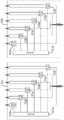
图6A:第一实施例中射频定位系统的方块示意图。FIG. 6A is a block diagram of the radio frequency positioning system in the first embodiment.
图6B:第一实施例中处理单元的方块示意图。FIG. 6B is a block diagram of the processing unit in the first embodiment.
图7:第二实施例中定位标签的方块示意图。FIG. 7 is a block diagram of the positioning label in the second embodiment.
图8:本发明射频定位方法中相位修正的步骤流程图。FIG. 8 is a flow chart of the steps of phase correction in the radio frequency positioning method of the present invention.
具体实施方式Detailed ways
请参看图1所示,本发明射频定位方法可通过一射频定位系统执行,该射频定位系统包含有:多个收发器10、至少一定位标签20、一信号模组30及一运算主机40。Referring to FIG. 1 , the radio frequency positioning method of the present invention can be implemented by a radio frequency positioning system, which includes a plurality of
如图2所示,各该收发器10包含有一发射电路11、一发射天线12、一接收电路13及一接收天线14,该发射电路11与该发射天线12连接,该接收电路13与该接收天线14连接;该发射电路11产生一发射信号,并通过该发射天线12发射与该发射信号相对应的一发射信号电磁波向外传输,该接收电路13则通过该接收天线14获取该至少一定位标签20传输的一调变信号电磁波,并产生一调变信号。As shown in FIG. 2 , each
如图3所示,各该定位标签20包含有至少一标签电路21及至少一标签天线22,且该至少一标签电路21的数量与该至少一标签天线22的数量相同,每一标签天线22对应电连接其中一标签电路21;以一个收发器10及一个定位标签20为例,该定位标签20中的该标签天线22接收该收发器10中该发射天线12对外传输的一发射信号电磁波,经该定位标签20中的该标签电路21加入对应该标签天线22的一识别码后,并通过该标签天线22产生该调变信号电磁波向外传输,其中,不同的标签天线22具有不同的识别码,根据不同的识别码即可辨识该调变信号电磁波由哪一个标签天线22发出。As shown in FIG. 3 , each of the
如图4A所示,该信号模组30连接各该收发器10,且包含有至少一处理单元31、一多工器32及一类比数字转换器33,该多工器32连接该至少一处理单元31,该类比数字转换器33连接该多工器32,每一个处理单元31会负责处理一个标签天线22所传输的该调变信号电磁波,因此该至少一处理单元31的数量与该至少一标签天线22的数量相同,而每一个处理单元31可连接每一个收发器10,以接收各该收发器10所传输的该调变信号,进一步参看图4B所示,各该处理单元31包含有一识别电路311及多个处理电路312,该多个处理电路312连接该识别电路311,且每一个处理电路312连接其中一个收发器10,因此该多个处理电路312的数量与该多个收发器10的数量相同,而该识别电路311提供对应各该标签天线22的识别信号给各该处理电路312,供各该处理电路312对该调变信号解调变而得到一接收信号,各该处理单元31将该发射信号与该接收信号混频以产生一中频信号并输出;该多工器32输出各该处理单元31产生的该中频信号至该类比数字转换器33,且该信号模组30借由该多工器32简化信号传输的通道数,减少该信号模组30所需要的类比数字转换器数量33;该类比数字转换器33将该多工器32传输的该中频信号由类比信号形式转换为数字信号形式向外传输。As shown in FIG. 4A , the
该运算主机40连接该类比数字转换器33的输出端,以获得每个处理电路312计算出的该中频信号,将该中频信号的一相位与一初始中频信号的一初始相位进行相位比对产生一相位差,并根据该相位差进行距离及位置坐标的运算,其中,该射频定位系统进行射频定位前可进行系统初始化程序,将各该收发器10及该至少一定位标签20分别置于已知的坐标位置,借由各该收发器10与该至少一定位标签20间双向的电磁波信号传输产生该初始中频信号。The
其中,本发明射频定位方法中该发射信号可通过频率调变,为了能够区别各该收发器10所产生的该发射信号,每个发射电路11可设计成不同的频率调变区间,达到分频多工;亦可设计成在不同时段依序产生发射信号,达到分时多工;又或者以分时分频的方式加以区分,使得同时间或同频率的发射信号不会重叠,达到区隔识别的目的。Wherein, in the radio frequency positioning method of the present invention, the transmission signal can be modulated by frequency. In order to distinguish the transmission signal generated by the
请参看图5A及图5B所示,本发明射频定位方法的步骤包含有:Please refer to FIG. 5A and FIG. 5B , the steps of the radio frequency positioning method of the present invention include:
S10:当该至少一定位标签20设置于一位置时,该至少一定位标签20与该多个收发器10进行信号传输,该运算主机40由该至少一定位标签20与该多个收发器10的信号传输取得多个中频信号,并计算各该中频信号的一信号强度,且步骤S10是包含以下步骤S101~S105。S10: When the at least one
S101:各该收发器10中的该发射电路11产生一发射信号,相对应的该发射天线12将该发射信号以电磁波形式产生一发射信号电磁波向外传输;S101: The transmitting
S102:该至少一定位标签20中的各该标签天线22接收该发射信号电磁波,各该标签电路21在该发射信号电磁波中加入与其相对应的该标签天线22的一识别码,通过各该标签天线22产生一调变信号电磁波向外传输;S102: Each of the
S103:各该收发器10的该接收天线14接收该调变信号电磁波,与该接收天线14相对应的该接收电路13根据该调变信号电磁波产生一调变信号,并将该调变信号传送至该信号模组30;S103: The receiving
S104:该信号模组30中各该处理单元31的该识别电路311产生对应各该标签天线22的一识别信号,各该处理电路312借由该识别信号对该调变信号解调变,产生一接收信号,且该信号模组30的各该处理单元31将该发射信号及该接收信号混频产生一中频信号,并由该信号模组30将各该中频信号经由该多工器32及该类比数字转换器33向外传输;S104: The
S105:该运算主机40接收各该中频信号,并计算各该中频信号的一信号强度。S105: The computing
S11:该运算主机40由预设的一强度门槛值判断各该中频信号的该信号强度是否足够,并剔除该信号强度不足的各该中频信号,而保留该信号强度大于或等于该强度门槛值的各该中频信号,并进行后续定位运算;S11: The computing
S12:该运算主机40将各该中频信号的一相位与对应的一初始中频信号的一初始相位做比对产生一相位差ΔФ;S12: The computing
S13:该运算主机40借由该相位差ΔФ,根据距离计算公式D=ΔD+D0及距离变化量的计算公式
S14:该运算主机40根据该至少一定位标签20中各该标签天线22与各该收发器10的距离计算各该标签天线22所在的一坐标位置,即可由各该标签天线22的该坐标位置得知该至少一定位标签20的坐标位置。S14: The computing
在步骤S14中,完成计算该至少一定位标签20中各该标签天线22所在的该坐标位置后,该运算主机40可将对应各该收发器10的该发射信号与该接收信号混频所得到的该中频信号定义为新的该初始中频信号,而该中频信号的该相位则定义为新的该初始相位,且该运算主机40将计算出的该收发器10与该至少一定位标签20中各该标签天线22的该距离定义为新的初始距离,以供下一轮定位时计算使用。In step S14 , after calculating the coordinate position of each of the
请参看图6A及图6B所示,第一实施例中,以包含有六个收发器10a~10f、一定位标签20、一信号模组30及一运算主机40的一射频定位系统为例,执行本发明射频定位方法,说明上述步骤S10~S14。本实施例中固定设置第一~第六收发器10a~10f于已知坐标位置(xa,ya,za)、(xb,yb,zb)、(xc,yc,zc)、(xd,yd,zd)、(xe,ye,ze)、(xf,yf,zf),而该些第一~第六收发器10a~10f分别与一信号模组30连接,该信号模组30包含有一第一处理单元31a、一第二处理单元31b、一多工器32及一类比数字转换器33,该多工器32与该第一处理单元31a及该第二处理单元31b连接,该类比数字转换器33与该多工器32连接,且该第一处理单元31a包含有一识别电路311a及六个处理电路312a~312f,该第二处理单元31b包含有一识别电路311b及六个处理电路312a~312f,该运算主机40与该信号模组30连接,而该定位标签20包含有两个标签电路21及两个标签天线22,为了方便说明以下的电路动作,在此特别将该定位标签20中一标签天线22标示为A1,而该标签天线A1对应的一标签天线21a。Referring to FIGS. 6A and 6B , in the first embodiment, taking a radio frequency positioning system including six
执行步骤S10之前,射频定位系统可将该定位标签20置于一初始位置进行初始化,使该运算主机40可储存有该定位标签20设置于该初始位置时,该第一~该第六收发器10a~10f分别与该定位标签20的该标签天线A1间的一初始距离DatA1~DftA1以及一初始中频信号SatA1”~SftA1”。Before step S10 is performed, the radio frequency positioning system can initialize the
首先,该定位标签20设置于一第一位置,以该标签天线A1为例,该第一收发器10a中的该发射电路11a产生一发射信号Sa,并通过与其连接的该发射天线12a发射与该发射信号Sa相对应的一发射信号电磁波Ea,且该发射信号Sa亦会传送至该处理单元31a的该处理电路312a中;该定位标签20通过该标签天线A1接收该发射信号电磁波Ea后,由该标签电路21a于该发射信号电磁波Ea中加入该标签天线A1的一识别码,再由该标签天线A1产生一调变信号电磁波Eat1A1向外传输;该接收天线14a接收该调变信号电磁波Eat1A1,接着该接收电路13a产生与该调变信号电磁波Eat1A1相对应的一调变信号Sat1A1。First, the
同理,该第二~该第六收发器10b~10f中的该些发射电路11b~11f依序产生发射信号Sb~Sf,并通过与其连接的该发射天线12b~12f输出相对应的发射信号电磁波Eb~Ef;该定位标签20通过该标签天线A1依序接收该些发射信号电磁波Eb~Ef,由该标签电路21a于该些发射信号电磁波Eb~Ef中加入该标签天线A1的一识别码,再通过该标签天线A1产生调变信号电磁波Ebt1A1~Eft1A1向外传输;该些接收天线14b~14f接收该些调变信号电磁波Ebt1A1~Eft1A1,接着该些接收电路13b~13f产生分别与该些调变信号电磁波相对应的调变信号Sbt1A1~Sft1A1。Similarly, the transmitting
该信号模组30中的该第一处理单元31a接收该第一收发器10a所传输对应于该标签天线A1的调变信号Sat1A1,该第一处理单元31a中该识别电路311a产生对应于该标签天线A1的一识别信号,供处理电路312a对调变信号Sat1A1解调变,产生相对应的接收信号Sat1A1';同理,该信号模组30中的该第一处理单元31a接收该第二~该第六收发器10b~10f所传输对应于该标签天线A1的调变信号Sbt1A1~Sft1A1,该第一处理单元31a中该识别电路311a产生对应于该标签天线A1的一识别信号,供处理电路312b~312f对调变信号Sbt1A1~Sft1A1解调变,产生相对应的接收信号Sbt1A1'~Sft1A1'。The
该第一处理单元31a将发射信号Sa~Sf分别与接收信号Sat1A1'~Sft1A1'进行混频,产生第一~第六收发器10a~10f对应于标签天线A1设置于该第一位置时的该些中频信号Sat1A1”~Sft1A1”。The
该运算主机40预设有一强度门槛值,且该运算主机40接收该些中频信号Sat1A1”~Sft1A1”并计算出该些中频信号Sat1A1”~Sft1A1”的一中频信号强度Iat1A1~Ift1A1,并将该些中频信号强度Iat1A1~Ift1A1与该强度门槛值比对,若该些中频信号强度低于该强度门槛值,则剔除低于该强度门槛值的该些中频信号,由高于或等于该强度门槛值的该些中频信号进行后续运算。The
在步骤S12中,以该第六收发器10f的该中频信号强度Ift1A1不足为例,该运算主机40由该些中频信号Sat1A1”~Set1A1”的一相位Фat1A1~Фet1A1分别与对应的初始中频信号SatA1”~SetA1”的一初始相位ФatA1~ФetA1进行相位比对,得到相位差ΔФat1A1、ΔФbt1A1、ΔФct1A1、ΔФdt1A1、ΔФet1A1。In step S12, taking an example that the intermediate frequency signal strength Ift1A1 of the
该运算主机40可由该些相位差ΔФat1A1~ΔФet1A1根据公式ΔD=λΔΦ/2π得知该标签天线A1设置于该第一位置时与该初始位置的距离变化量ΔDat1A1、ΔDbt1A1、ΔDct1A1、ΔDdt1A1、ΔDet1A1,并根据距离D=距离变化量ΔD+初始距离D0得到下列关系式:The
Dat1A1=ΔDat1A1+DatA1Dat1A1 =ΔDat1A1 +DatA1
Dbt1A1=ΔDbt1A1+DbtA1Dbt1A1 =ΔDbt1A1 +DbtA1
Dct1A1=ΔDct1A1+DctA1Dct1A1 = ΔDct1A1 +DctA1
Ddt1A1=ΔDdt1A1+DdtA1Ddt1A1 =ΔDdt1A1 +DdtA1
Det1A1=ΔDet1A1+DetA1Det1A1 = ΔDet1A1 + DetA1
再由该运算主机40由下列关系矩阵得知该定位标签20中该标签天线A1的一坐标位置(xt1A1,yt1A1,zt1A1):Then, the


而若以该第五收发器10e的该中频信号强度Iet1A1以及该第六收发器10f的该中频信号强度Ift1A1不足为例,该运算主机40由该些中频信号Sat1A1”~Sdt1A1”分别与对应的初始中频信号SatA1”~SdtA1”进行相位比对,得到相位差ΔФat1A1、ΔФbt1A1、ΔФct1A1、ΔФdt1A1。And if the intermediate frequency signal strength I et1A1 of the
该运算主机40可由该些相位差ΔФat1A1~ΔФdt1A1根据公式ΔD=λΔΦ/2π得知该标签天线A1设置于该第一位置时与该初始位置的距离变化量ΔDat1A1、ΔDbt1A1、ΔDct1A1、ΔDdt1A1,并根据距离D=距离变化量ΔD+初始距离D0得到下列关系式:The
Dat1A1=ΔDat1A1+DatA1Dat1A1 =ΔDat1A1 +DatA1
Dbt1A1=ΔDbt1A1+DbtA1Dbt1A1 =ΔDbt1A1 +DbtA1
Dct1A1=ΔDct1A1+DctA1Dct1A1 = ΔDct1A1 +DctA1
Ddt1A1=ΔDdt1A1+DdtA1Ddt1A1 =ΔDdt1A1 +DdtA1
再由该运算主机40通过该第一~第四收发器10a~10d的已知坐标位置(xa,ya,za)、(xb,yb,zb)、(xc,yc,zc)、(xd,yd,zd),根据以下关系式计算该标签天线A1的坐标位置:Then, the

请参看图7所示,于一第二实施例中,第一实施例的该定位标签20可包含有三个标签电路21及三个标签天线22,为了方便说明以下的电路动作,在此特别将该定位标签20的三个标签天线22分别标示为A1、A2及A3。Referring to FIG. 7 , in a second embodiment, the
同理,该运算主机40可根据上述流程得知该些标签天线A1、A2、A3的坐标位置(xt1A1,yt1A1,zt1A1)、(xt1A2,yt1A2,zt1A2)、(xt1A3,yt1A3,zt1A3)。Similarly, the
当该运算主机40得知该些标签天线A1~A3坐标位置后,可进一步依下式计算该定位标签20的方位(u,v,w)。After the
u=(xt1A2-xt1A1,yt1A2-yt1A1,2t1A2-zt1A1)u=(xt1A2 -xt1A1 ,yt1A2 -yt1A1 ,2t1A2 -zt1A1 )
v′=(xt1A3-xt1A1,yt1A3-yt1A1,zt1A3-zt1A1)v′=(xt1A3 -xt1A1 ,yt1A3 -yt1A1 ,zt1A3 -zt1A1 )
w=u×v′w=u×v′
v=w×uv=w×u
请参看图8所示,当完成步骤S14后,若步骤S11中该运算主机40判断有信号强度不足的中频信号时,本发明射频定位方法执行以下相位修正流程:Referring to FIG. 8 , after step S14 is completed, if the
S201:该运算主机40由该至少一标签天线22的坐标位置计算步骤S11中信号强度不足的各该中频信号所对应的各该收发器10与该至少一标签天线22的一修正距离。S201 : The computing
S202:该运算主机40由该修正距离计算信号强度不足的各该中频信号所对应的各该收发器10与该至少一标签天线22的一修正相位差。S202: The computing
S203:该运算主机40由该修正相位差计算信号强度不足的各该中频信号的一修正相位。S203: The computing
S204:该运算主机40将信号强度不足的各该中频信号定义为新的该初始中频信号,而各该修正相位则定义为新的该初始相位,且该运算主机40将信号强度不足的中频信号所对应的各该收发器10与标签天线22的该修正距离定义为新的该初始距离,并回到步骤S10进行新一轮的定位流程。S204: The computing
配合图6A及图6B所示,以第一实施例中包含有六个收发器10a~10f、该定位标签20、该信号模组30及该运算主机40的该射频定位系统为例,并接续第一实施例,说明上述步骤S201~S204。6A and 6B, take the radio frequency positioning system including six
若以该运算主机40判断该第六收发器10f的该中频信号强度Ift1A1不足为例,该运算主机40由下列关系式计算该第六收发器10f与该标签天线A1的一修正距离Dft1A1:If the

接着该运算主机40通过该修正距离,根据相位差公式ΔΦ=(D-D0)2π/λ,D为收发器10与标签天线22的距离,D0为收发器10与标签天线22的初始距离,以下列关系式计算对应该第六收发器10f与该标签天线A1的该中频信号与该初始中频信号的一修正相位差:Then the
ΔΦft1A1=(Dft1A1-DftA1)2π/λΔΦft1A1 =(Dft1A1 -DftA1 )2π/λ
该运算主机40由该修正相位差,根据相位公式Φ=Φ0+ΔΦ,以下列关系式计算对应该第六收发器10f与该标签天线A1的该中频信号的一修正相位:Based on the corrected phase difference, the
Φft1A1=ΦftA1+ΔΦft1A1Φft1A1 = ΦftA1 +ΔΦft1A1
最后该运算主机40将对应该第六收发器10f与该标签天线A1的该中频信号定义为新的初始中频信号,而该中频信号的该修正相位Φft1A1定义为新的初始相位,并将该第六收发器10f与该标签天线A1的该修正距离Dft1A1定义为新的初始距离,以供进行新一轮定位时该运算主机40执行步骤S12及步骤S13。Finally, the
完成该定位标签20设置于该第一位置时的定位以及相位修正后,可将该定位标签20设置于一第二位置执行下一轮定位。After completing the positioning and phase correction when the
同样以该标签天线A1为例,该第一收发器10a中的该发射电路11a产生一发射信号Sa,并通过与其连接的该发射天线12a发射与该发射信号Sa相对应的一发射信号电磁波Ea,且该发射信号Sa亦会传送至该处理单元31a的该处理电路312a中;该定位标签20通过该标签天线A1接收该发射信号电磁波Ea后,由该标签电路21a于该发射信号电磁波Ea中加入该标签天线A1的一识别码,再由该标签天线A1产生一调变信号电磁波Eat2A1向外传输;该接收天线14a接收该调变信号电磁波Eat2A1,接着该接收电路13a产生与该调变信号电磁波Eat2A1相对应的一调变信号Sat2A1。Taking the tag antenna A1 as an example, the transmitting circuit 11a in the
同理,该第二~该第六收发器10b~10f中的该些发射电路11b~11f依序产生发射信号Sb~Sf,并通过与其连接的该发射天线12b~12f输出相对应的发射信号电磁波Eb~Ef;该定位标签20通过该标签天线A1依序接收该些发射信号电磁波Eb~Ef,由该标签电路21a于该些发射信号电磁波Eb~Ef中加入该标签天线A1的一识别码,再通过该标签天线A1产生调变信号电磁波Ebt2A1~Eft2A1向外传输;该些接收天线14b~14f接收该些调变信号电磁波Ebt2A1~Eft2A1,接着该些接收电路13b~13f产生分别与该些调变信号电磁波相对应的调变信号Sbt2A1~Sft2A1。Similarly, the transmitting
该信号模组30中的该第一处理单元31a接收该第一收发器10a所传输对应于该标签天线A1的调变信号Sat2A1,该第一处理单元31a中该识别电路311a产生对应于该标签天线A1的一识别信号,供处理电路312a对调变信号Sat2A1解调变,产生相对应的接收信号Sat2A1';同理,该信号模组30中的该第一处理单元31a接收该第二~该第六收发器10b~10f所传输对应于该标签天线A1的调变信号Sbt2A1~Sft2A1,该第一处理单元31a中该识别电路311a产生对应于该标签天线A1的一识别信号,供处理电路312b~312f对调变信号Sbt2A1~Sft2A1解调变,产生相对应的接收信号Sbt2A1'~Sft2A1'。The
该第一处理单元31a将发射信号Sa~Sf分别与接收信号Sat2A1'~Sft2A1'进行混频,产生第一~第六收发器10a~10f对应于标签天线A1设置于该第二位置时的该些中频信号Sat2A1”~Sft2A1”。The
该运算主机40预设有一强度门槛值,且该运算主机40计算出该些中频信号Sat2A1”~Sft2A1”的一中频信号强度Iat2A1~Ift2A1,并将该些中频信号强度Iat2A1~Ift2A1与该强度门槛值比对,若该些中频信号强度低于该强度门槛值,则剔除低于该强度门槛值的该些中频信号,由高于或等于该强度门槛值的该些中频信号进行后续运算。The
在步骤S12中,以该第六收发器10f的该中频信号强度Ift2A1不足为例,该运算主机40由该些中频信号Sat2A1”~Set2A1”的一相位Фat2A1~Фet2A1分别与对应的新的初始中频信号Sat1A1”~Set1A1”的一初始相位Фat1A1~Фet1A1进行相位比对,得到相位差ΔФat2A1、ΔФbt2A1、ΔФct2A1、ΔФdt2A1、ΔФet2A1。In step S12, taking an example that the intermediate frequency signal strength Ift2A1 of the
该运算主机40可由该些相位差ΔФat2A1~ΔФet2A1根据公式ΔD=λΔΦ/2π得知该标签天线A1设置于该第二位置时与该初始位置的距离变化量ΔDat2A1、ΔDbt2A1、ΔDct2A1、ΔDdt2A1、ΔDet2A1,并根据距离D=距离变化量ΔD+初始距离D0得到下列关系式:The
Dat2A1=ΔDat2A1+Dat1A1Dat2A1 =ΔDat2A1 +Dat1A1
Dbt2A1=ΔDbt2A1+Dbt1A1Dbt2A1 =ΔDbt2A1 +Dbt1A1
Dct2A1=ΔDct2A1+Dct1A1Dct2A1 = ΔDct2A1 + Dct1A1
Ddt2A1=ΔDdt2A1+Ddt1A1Ddt2A1 =ΔDdt2A1 +Ddt1A1
Det2A1=ΔDet2A1+Det1A1Det2A1 = ΔDet2A1 + Det1A1
再由该运算主机40由下列关系矩阵得知该定位标签20中该标签天线A1的一坐标位置(xt2A1,yt2A1,zt2A1):Then, the


综上所述,本发明可基于该多个收发器10与该至少一定位标签20之间双向电磁波信号传输,定位找出该至少一定位标签20中各该标签天线22的坐标位置,并可借由多个标签天线22的坐标位置计算该至少一定位标签20的方位,使本发明可供应用于手术定位装置,于手术中精准运算安装于手术器械及病患患部的该至少一定位标签20的位置及方位,另一方面,该至少一定位标签20与各该收发器10相互对应的角度不同或是受物件屏蔽时,会影响各该发射信号及各该调变信号的信号强度,造成后续产生的各该接收信号与各该中频信号的信号强度不足,使得各该中频信号受到杂讯干扰,进而影响该运算主机40进行坐标运算,本发明可借由剔除信号强度不足的各该中频信号,避免该运算主机40后续的定位运算产生误差,提升本发明定位方法的定位精准度,且本发明包含定位后的相位修正流程,由定位流程中计算出的定位坐标,反向计算出信号强度不足的各该中频信号的一修正相位,使对应信号强度不足的各该中频信号的各该收发器10能继续应用于后续的定位流程中,提升本发明射频定位方法的定位稳定性。To sum up, the present invention can locate and find the coordinate position of each
Claims (10)
Translated fromChinese

Applications Claiming Priority (2)
| Application Number | Priority Date | Filing Date | Title |
|---|---|---|---|
| TW109139973 | 2020-11-16 | ||
| TW109139973ATWI751790B (en) | 2020-11-16 | 2020-11-16 | Radio frequency positioning method |
Publications (1)
| Publication Number | Publication Date |
|---|---|
| CN114509747Atrue CN114509747A (en) | 2022-05-17 |
Family
ID=80809155
Family Applications (1)
| Application Number | Title | Priority Date | Filing Date |
|---|---|---|---|
| CN202110928557.1APendingCN114509747A (en) | 2020-11-16 | 2021-08-13 | radio frequency positioning method |
Country Status (2)
| Country | Link |
|---|---|
| CN (1) | CN114509747A (en) |
| TW (1) | TWI751790B (en) |
Citations (10)
| Publication number | Priority date | Publication date | Assignee | Title |
|---|---|---|---|---|
| US20040027243A1 (en)* | 2002-08-09 | 2004-02-12 | Battelle Memorial Institute | System and method for acquisition management of subject position information |
| JP2008102102A (en)* | 2006-10-20 | 2008-05-01 | Brother Ind Ltd | Wireless device detection apparatus and wireless device detection method |
| US20100013711A1 (en)* | 2007-01-08 | 2010-01-21 | David Bartlett | Determining a position of a tag |
| US20100052857A1 (en)* | 2008-09-04 | 2010-03-04 | Ncr Corporation | Methods and Apparatus for Distance Determination for Radiofrequency Identification Devices |
| TW201142338A (en)* | 2010-05-31 | 2011-12-01 | Uniband Electronic Corp | Apparatus for positioning using average phase difference and method for the same |
| US20140300516A1 (en)* | 2011-11-10 | 2014-10-09 | Position Imaging, Inc. | Systems and methods of wireless position tracking |
| CN107864510A (en)* | 2017-12-26 | 2018-03-30 | 厦门大学 | A kind of indoor orientation method, terminal device and storage medium suitable for nuclear island of nuclear power station |
| CN109001675A (en)* | 2018-08-03 | 2018-12-14 | 电子科技大学 | A kind of localization method based on phase difference measurement range difference |
| CN109375167A (en)* | 2018-07-12 | 2019-02-22 | 中国矿业大学 | Downhole passive moving target localization method |
| CN111257831A (en)* | 2018-11-30 | 2020-06-09 | 财团法人金属工业研究发展中心 | Radio frequency positioning system |
Family Cites Families (2)
| Publication number | Priority date | Publication date | Assignee | Title |
|---|---|---|---|---|
| JP4265686B2 (en)* | 2005-03-09 | 2009-05-20 | オムロン株式会社 | Distance measuring device, distance measuring method, reflector, and communication system |
| JP6573936B2 (en)* | 2017-06-02 | 2019-09-11 | チームラボ株式会社 | Terminal device, computer program, and system for position measurement |
- 2020
- 2020-11-16TWTW109139973Apatent/TWI751790B/enactive
- 2021
- 2021-08-13CNCN202110928557.1Apatent/CN114509747A/enactivePending
Patent Citations (10)
| Publication number | Priority date | Publication date | Assignee | Title |
|---|---|---|---|---|
| US20040027243A1 (en)* | 2002-08-09 | 2004-02-12 | Battelle Memorial Institute | System and method for acquisition management of subject position information |
| JP2008102102A (en)* | 2006-10-20 | 2008-05-01 | Brother Ind Ltd | Wireless device detection apparatus and wireless device detection method |
| US20100013711A1 (en)* | 2007-01-08 | 2010-01-21 | David Bartlett | Determining a position of a tag |
| US20100052857A1 (en)* | 2008-09-04 | 2010-03-04 | Ncr Corporation | Methods and Apparatus for Distance Determination for Radiofrequency Identification Devices |
| TW201142338A (en)* | 2010-05-31 | 2011-12-01 | Uniband Electronic Corp | Apparatus for positioning using average phase difference and method for the same |
| US20140300516A1 (en)* | 2011-11-10 | 2014-10-09 | Position Imaging, Inc. | Systems and methods of wireless position tracking |
| CN107864510A (en)* | 2017-12-26 | 2018-03-30 | 厦门大学 | A kind of indoor orientation method, terminal device and storage medium suitable for nuclear island of nuclear power station |
| CN109375167A (en)* | 2018-07-12 | 2019-02-22 | 中国矿业大学 | Downhole passive moving target localization method |
| CN109001675A (en)* | 2018-08-03 | 2018-12-14 | 电子科技大学 | A kind of localization method based on phase difference measurement range difference |
| CN111257831A (en)* | 2018-11-30 | 2020-06-09 | 财团法人金属工业研究发展中心 | Radio frequency positioning system |
Non-Patent Citations (4)
| Title |
|---|
| CUI YINGHUA: "Distributed multiple antenna reader positioning system for fast moving objects", SCIENCE & TECHNOLOGY REVIEW, vol. 35, no. 18, 28 September 2017 (2017-09-28), pages 58 - 63* |
| 杨小亮 等: "基于阈值分类及信号强度加权的室内定位算法", 计算机应用, vol. 33, no. 10, 1 October 2013 (2013-10-01), pages 2711 - 2714* |
| 蓝威涛 等: "基于相位差测距的RFID室内定位系统设计", 传感器与微系统, vol. 36, no. 10, 10 October 2017 (2017-10-10), pages 85 - 88* |
| 邱兰馨 等: "一种基于多相位差的RFID标签三维定位方法", 计算机学报, vol. 42, no. 11, 19 August 2017 (2017-08-19), pages 2512 - 2525* |
Also Published As
| Publication number | Publication date |
|---|---|
| TW202221352A (en) | 2022-06-01 |
| TWI751790B (en) | 2022-01-01 |
Similar Documents
| Publication | Publication Date | Title |
|---|---|---|
| US8435171B2 (en) | Interface between a surgeon and an automated assistant and method thereof | |
| RU2472435C2 (en) | System for determining position of medical instrument | |
| US5782765A (en) | Medical positioning system | |
| WO1999027837A2 (en) | System and method for guiding the movements of a device to a target particularly for medical applications | |
| RU2018138151A (en) | DETERMINATION OF LOCATION BY WIRELESS COMMUNICATION | |
| CN1576883A (en) | Electromagnetic tracking system and method using a single-coil transmitter | |
| CN112881980A (en) | Multi-target radio frequency positioning system, positioning method and initial distance measuring method | |
| EP2208463B1 (en) | Interface between a surgeon and an automated assistant and method thereof | |
| US20060213830A1 (en) | In-situ groundwater nitrification and de-nitrification remediation system | |
| TWI695989B (en) | Rf positioning system | |
| CN114509747A (en) | radio frequency positioning method | |
| CN117172270A (en) | RFID (radio frequency identification) mapping system based on magnetic positioning reference | |
| TWI580987B (en) | A positioning algorithm for calculating the positioning distance | |
| US20060210277A1 (en) | Method and arrangement for the wireless control of a device, in particular in the field of medicine | |
| TWI593987B (en) | FM radar transceiver | |
| JPH02262727A (en) | Communication system for data transmission between sending and receiving platforms | |
| TWI720711B (en) | Radio frequency positioning method for measuring the position of transceiver | |
| CN113109800A (en) | Radio frequency positioning method for measuring position of transceiver | |
| JP4115379B2 (en) | Transmission / reception system | |
| US20230157668A1 (en) | System and method for wirelessly powering, sending and receiving information from an instrument in the body | |
| JP6992589B2 (en) | Phase adjuster and wireless device | |
| US20250275811A1 (en) | Electromagnetic sensor | |
| US20240225474A1 (en) | Systems and methods for identifying and locating markers using rfid and orthogonal sequences | |
| US11454695B2 (en) | Dynamic power positioning method and dynamic power positioning system thereof | |
| JP7515127B2 (en) | Estimation system, estimation method, and program |
Legal Events
| Date | Code | Title | Description |
|---|---|---|---|
| PB01 | Publication | ||
| PB01 | Publication | ||
| SE01 | Entry into force of request for substantive examination | ||
| SE01 | Entry into force of request for substantive examination | ||
| WD01 | Invention patent application deemed withdrawn after publication | ||
| WD01 | Invention patent application deemed withdrawn after publication | Application publication date:20220517 |