CN114505812A - Hand-held power tool with an activation unit - Google Patents
Hand-held power tool with an activation unitDownload PDFInfo
- Publication number
- CN114505812A CN114505812ACN202111353188.4ACN202111353188ACN114505812ACN 114505812 ACN114505812 ACN 114505812ACN 202111353188 ACN202111353188 ACN 202111353188ACN 114505812 ACN114505812 ACN 114505812A
- Authority
- CN
- China
- Prior art keywords
- tool
- receptacle
- hand
- drive motor
- held power
- Prior art date
- Legal status (The legal status is an assumption and is not a legal conclusion. Google has not performed a legal analysis and makes no representation as to the accuracy of the status listed.)
- Pending
Links
Images


Classifications
- B—PERFORMING OPERATIONS; TRANSPORTING
- B25—HAND TOOLS; PORTABLE POWER-DRIVEN TOOLS; MANIPULATORS
- B25F—COMBINATION OR MULTI-PURPOSE TOOLS NOT OTHERWISE PROVIDED FOR; DETAILS OR COMPONENTS OF PORTABLE POWER-DRIVEN TOOLS NOT PARTICULARLY RELATED TO THE OPERATIONS PERFORMED AND NOT OTHERWISE PROVIDED FOR
- B25F5/00—Details or components of portable power-driven tools not particularly related to the operations performed and not otherwise provided for
- B25F5/02—Construction of casings, bodies or handles
- B—PERFORMING OPERATIONS; TRANSPORTING
- B25—HAND TOOLS; PORTABLE POWER-DRIVEN TOOLS; MANIPULATORS
- B25B—TOOLS OR BENCH DEVICES NOT OTHERWISE PROVIDED FOR, FOR FASTENING, CONNECTING, DISENGAGING OR HOLDING
- B25B21/00—Portable power-driven screw or nut setting or loosening tools; Attachments for drilling apparatus serving the same purpose
- B—PERFORMING OPERATIONS; TRANSPORTING
- B25—HAND TOOLS; PORTABLE POWER-DRIVEN TOOLS; MANIPULATORS
- B25B—TOOLS OR BENCH DEVICES NOT OTHERWISE PROVIDED FOR, FOR FASTENING, CONNECTING, DISENGAGING OR HOLDING
- B25B23/00—Details of, or accessories for, spanners, wrenches, screwdrivers
- B—PERFORMING OPERATIONS; TRANSPORTING
- B25—HAND TOOLS; PORTABLE POWER-DRIVEN TOOLS; MANIPULATORS
- B25B—TOOLS OR BENCH DEVICES NOT OTHERWISE PROVIDED FOR, FOR FASTENING, CONNECTING, DISENGAGING OR HOLDING
- B25B23/00—Details of, or accessories for, spanners, wrenches, screwdrivers
- B25B23/14—Arrangement of torque limiters or torque indicators in wrenches or screwdrivers
Landscapes
- Engineering & Computer Science (AREA)
- Mechanical Engineering (AREA)
- Portable Power Tools In General (AREA)
- Details Of Spanners, Wrenches, And Screw Drivers And Accessories (AREA)
Abstract
Description
Translated fromChinese技术领域technical field
本发明涉及一种手持式工具机、尤其是起子机,其具有:长形壳体,在该壳体中布置有具有至少一个驱动马达的驱动单元,用于驱动工具接收部,其中,所述工具接收部构造为用于接收插入式工具;和用于激活驱动马达的激活单元,其中,通过将布置在工具接收部中的插入式工具尤其沿着手持式工具机的纵轴线抵着待加工的工件加载,实现驱动马达的激活。The invention relates to a hand-held power tool, in particular a screwdriver, having an elongated housing in which a drive unit with at least one drive motor is arranged for driving a tool receptacle, wherein the The tool receptacle is designed to receive a plug-in tool; and an activation unit for activating the drive motor, wherein the plug-in tool, which is arranged in the tool receptacle, is pressed against the to-be-machined tool, in particular along the longitudinal axis of the hand-held power tool. The workpiece is loaded to realize the activation of the drive motor.
背景技术Background technique
由现有技术已知这种构造为杆式起子机的手持式工具机。该杆式起子机在壳体中具有用于驱动所配属的工具接收部的驱动马达。通过将布置在工具接收部中的插入式工具抵着待加工的工件加载,实现驱动马达的激活或者说配属于驱动马达的开关元件的激活。该开关元件布置在驱动马达的区域中并且为了激活驱动马达而必须使整个驱动单元沿着手持式工具机的纵轴线移动。Such hand-held power tools are known from the prior art, which are designed as rod screwdrivers. The rod driver has a drive motor in the housing for driving the associated tool receptacle. The activation of the drive motor or the activation of the switching element associated with the drive motor takes place by loading the insert tool arranged in the tool receptacle against the workpiece to be machined. The switching element is arranged in the region of the drive motor and in order to activate the drive motor, the entire drive unit must be moved along the longitudinal axis of the hand-held power tool.
发明内容SUMMARY OF THE INVENTION
本发明涉及一种手持式工具机、尤其是起子机,其具有:长形壳体,在该壳体中布置有具有至少一个驱动马达的驱动单元,用于驱动工具接收部,其中,所述工具接收部构造为用于接收插入式工具;和用于激活驱动马达的激活单元,其中,通过将布置在工具接收部中的插入式工具尤其沿着手持式工具机的纵轴线抵着待加工的工件加载,实现驱动马达的激活。激活单元具有布置在工具接收部区域中的马达开关以及布置在工具接收部的外周上的、用于操纵马达开关的操纵元件,其中,工具接收部具有面向驱动马达的内接收部,用于接收配属于激活单元的弹簧元件,通过加载工具接收部,该弹簧元件将操纵元件朝离开驱动马达指向的方向加载,用于停用驱动马达。The invention relates to a hand-held power tool, in particular a screwdriver, having an elongated housing in which a drive unit with at least one drive motor is arranged for driving a tool receptacle, wherein the The tool receptacle is designed to receive a plug-in tool; and an activation unit for activating the drive motor, wherein the plug-in tool, which is arranged in the tool receptacle, is pressed against the to-be-machined tool, in particular along the longitudinal axis of the hand-held power tool. The workpiece is loaded to realize the activation of the drive motor. The activation unit has a motor switch arranged in the region of the tool receptacle and an actuating element arranged on the outer circumference of the tool receptacle for actuating the motor switch, wherein the tool receptacle has an inner receptacle facing the drive motor for receiving A spring element, which is assigned to the activation unit, acts via the charging tool receptacle to actuate the actuating element in a direction pointing away from the drive motor for deactivating the drive motor.
因此,本发明能够提供一种手持式工具机,在该手持式工具机中,通过将配属于激活单元的弹簧元件布置在工具接收部的内接收部中可以提供紧凑的激活单元。The present invention thus makes it possible to provide a hand-held power tool in which a compact activation unit can be provided by arranging the spring element assigned to the activation unit in the inner receptacle of the tool receptacle.
优选地,通过对工具接收部的加载,弹簧元件能够朝驱动马达的方向被压缩,以便能够通过操纵元件释放或操纵马达开关和因此能够激活驱动马达。Preferably, by loading the tool receptacle, the spring element can be compressed in the direction of the drive motor, so that the motor switch can be released or actuated by the actuating element and thus the drive motor can be activated.
因此,能够以简单的方式实现驱动马达的激活。Thus, activation of the drive motor can be achieved in a simple manner.
工具接收部优选在其外周上在内接收部的区域中具有转矩联接器。The tool receptacle preferably has a torque coupling on its outer circumference in the region of the inner receptacle.
因此可以容易地并不复杂地提供具有转矩联接器的手持式工具机。Thus, a hand-held power tool with a torque coupling can be provided easily and without complexity.
根据一个实施方式,转矩联接器具有用于调设可预给定的转矩的调设套筒和具有弹簧保持环,其中,调设套筒通过啮合部直接与弹簧保持环连接。According to one embodiment, the torque coupling has a setting sleeve for setting a predeterminable torque and has a spring retaining ring, wherein the setting sleeve is directly connected to the spring retaining ring by means of a toothing.
因此,能够实现转矩联接器的结构空间减小的布置方式。As a result, an arrangement with a reduced installation space of the torque coupling can be achieved.
优选地,工具接收部在其外周上具有支撑元件,其中,操纵元件贴靠在支撑元件上并且借助保险元件轴向地被保险。Preferably, the tool receptacle has a support element on its outer circumference, wherein the actuating element rests on the support element and is secured axially by means of a securing element.
因此,能够实现操纵元件在工具接收部的外周上的可靠且稳固的布置。Thus, a reliable and stable arrangement of the actuating element on the outer circumference of the tool receptacle can be achieved.
驱动单元优选具有传动装置、尤其是行星齿轮传动装置,并且传动装置布置在传动装置壳体中,其中,传动装置壳体的面向工具接收部的端面在驱动马达停用时用作操纵元件的轴向贴靠面。The drive unit preferably has a gear, in particular a planetary gear, and the gear is arranged in the gear housing, wherein the end face of the gear housing facing the tool receptacle serves as a shaft for the actuating element when the drive motor is deactivated toward the contact surface.
因此,能够以简单的方式实现操纵元件在手持式工具机中的稳定且可靠的布置。Thus, a stable and reliable arrangement of the actuating element in the hand-held power tool can be achieved in a simple manner.
根据一个实施方式,传动装置具有从动元件,其中,从动元件插入到工具接收部的内接收部中。According to one embodiment, the transmission has a driven element, wherein the driven element is inserted into the inner receptacle of the tool receptacle.
因此,能够实现弹簧元件在内接收部中可靠且不复杂地布置在从动元件上。Thus, a reliable and uncomplicated arrangement of the spring element on the driven element in the inner receptacle can be achieved.
优选地,工具接收部构造为相对于从动元件可轴向地移动。Preferably, the tool receiver is configured to be axially movable relative to the driven element.
因此,能够以简单的方式通过工具接收部相对于驱动马达的移动来实现驱动马达的激活和停用。Thus, activation and deactivation of the drive motor can be achieved in a simple manner by a movement of the tool receiver relative to the drive motor.
优选地,从动元件具有用于接收弹簧元件的内接收部,其中,弹簧元件布置在从动元件、尤其是其内接收部与工具接收部、尤其是其内接收部之间。Preferably, the output element has an inner receptacle for receiving the spring element, wherein the spring element is arranged between the output element, in particular its inner receptacle, and the tool receptacle, in particular its inner receptacle.
因此,能够实现弹簧元件的可靠布置,通过该布置可以提供紧凑的驱动单元。Thus, a reliable arrangement of the spring elements can be achieved, by means of which a compact drive unit can be provided.
传动装置优选具有至少一个轴承元件,用于可转动地支承工具接收部,其中,轴承元件布置在工具接收部与传动装置壳体之间。The gear preferably has at least one bearing element for rotatably supporting the tool receptacle, wherein the bearing element is arranged between the tool receptacle and the gear housing.
因此,能够实现手持式工具机、尤其是用于驱动插入式工具的工具接收部的安全和可靠的运行。As a result, safe and reliable operation of the hand-held power tool, in particular of the tool receptacle for driving the plug-in tool, can be achieved.
根据一个实施方式,激活单元具有电路板,该电路板在长形壳体中布置在长形壳体的端侧的区域中,其中,马达开关布置在电路板上并且构造为马达断路器,其中,通过加载工具接收部,弹簧元件将操纵元件抵着马达断路器加载,用于停用驱动马达。According to one embodiment, the activation unit has a circuit board, which is arranged in the elongated housing in the region of an end face of the elongated housing, wherein the motor switch is arranged on the circuit board and is designed as a motor circuit breaker, wherein , via the loading tool receiver, the spring element loads the actuating element against the motor breaker for deactivating the drive motor.
因此,通过持续地操纵马达断路器能够实现手持式工具机的安全和可靠的停用,该停用可以通过加载工具接收部和从而加载操纵元件离开马达断路器以简单的方式结束。Thus, a safe and reliable deactivation of the hand-held power tool can be achieved by continuously actuating the motor circuit breaker, which deactivation can be ended in a simple manner by leaving the charging tool receptacle and thus the charging actuating element off the motor circuit breaker.
根据另一实施方式,马达开关布置在传动装置壳体的端面上,该端面面向壳体的第一轴向端部。According to another embodiment, the motor switch is arranged on an end face of the transmission housing which faces the first axial end of the housing.
因此,能够以简单的方式实现马达开关在手持式工具机中的替代布置方式。Thus, an alternative arrangement of the motor switch in the hand-held power tool can be realized in a simple manner.
优选地,马达开关构造为马达闭路器,其中,通过加载工具接收部,弹簧元件将操纵元件朝离开马达闭路器指向的方向加载,用于停用驱动马达。Preferably, the motor switch is designed as a motor circuit breaker, wherein the actuating element is acted upon by the spring element in a direction pointing away from the motor circuit breaker for deactivating the drive motor by means of the charging tool receptacle.
因此,能够简单并不复杂地通过不操纵马达闭路器实现手持式工具机的持久的停用,该停用可以通过加载工具接收部和从而将操纵元件抵着马达闭路器加载以简单的方式结束。Thus, a permanent deactivation of the hand-held power tool can be achieved in a simple and uncomplicated manner without actuating the motor circuit breaker, which deactivation can be ended in a simple manner by loading the tool receptacle and thus the actuating element against the motor circuit breaker. .
附图说明Description of drawings
在下面的说明中根据附图中示出的实施例详细地阐述本发明。附图示出了:The invention is explained in detail in the following description based on the exemplary embodiments shown in the drawings. The attached figure shows:
图1根据本发明的手持式工具机的侧视图,1 is a side view of the hand-held power tool according to the invention,
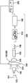
图2图1的手持式工具机示意图,其具有电路板,Fig. 2 is a schematic diagram of the hand-held power tool of Fig. 1, which has a circuit board,
图3图1和图2的手持式工具机的示意图,其具有根据另一实施方式的电路板,FIG. 3 is a schematic illustration of the hand-held power tool of FIGS. 1 and 2 with a circuit board according to a further embodiment,
图4图1至图3的手持式工具机的示意图,其具有替代的电路板,4 is a schematic illustration of the hand-held power tool of FIGS. 1 to 3 with an alternative circuit board,
图5配属于图1至图4的手持式工具机的工具接收部的立体分解图,其具有配属的激活单元,FIG. 5 is an exploded perspective view of the tool receptacle of the hand-held power tool of FIGS. 1 to 4 with the associated activation unit,
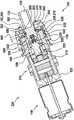
图6在激活状态下的配属于手持式工具机的驱动单元的纵截面,FIG. 6 is a longitudinal section through the drive unit associated with the hand-held power tool in the activated state,
图7在停用状态下的图6的驱动单元纵截面的放大视图,7 is an enlarged view of the longitudinal section of the drive unit of FIG. 6 in the deactivated state,
图8在激活状态下的图6和图7的驱动单元纵截面的放大视图,其具有转矩联接器,FIG. 8 is an enlarged view of the longitudinal section of the drive unit of FIGS. 6 and 7 in the activated state, with the torque coupling,
图9在停用状态下的图6和图7的驱动单元纵截面的放大视图,其具有图8的转矩联接器,FIG. 9 is an enlarged view of the longitudinal section of the drive unit of FIGS. 6 and 7 with the torque coupling of FIG. 8 in the deactivated state,
图10图1至图9的手持式工具机的示意图,其具有配属于激活单元的、处于另一位置处的马达开关,FIG. 10 is a schematic illustration of the hand-held power tool from FIGS. 1 to 9 with a motor switch associated with the activation unit in another position,
图11图6和图7的驱动单元的纵截面的放大视图,其处于图10的马达开关的停用状态下,和Figure 11 is an enlarged view of a longitudinal section of the drive unit of Figures 6 and 7 in the deactivated state of the motor switch of Figure 10, and
图12在图10和图11的马达开关的激活状态下的图11的纵截面的放大视图。FIG. 12 is an enlarged view of the longitudinal section of FIG. 11 in the activated state of the motor switch of FIGS. 10 and 11 .
在附图中,具有相同或类似功能的元件设有相同的附图标记并且仅详细地描述一次。In the figures, elements having the same or similar functions are provided with the same reference numerals and are described in detail only once.
具体实施方式Detailed ways
图1示出示例性的手持式工具机100,其图示地具有长形壳体110。因此,通过长形壳体110,手持式工具机100示例性地以所谓的“杆形状”构造。FIG. 1 shows an exemplary hand-held
优选地,手持式工具机100构造为起子机、尤其是杆式起子机。根据一个实施方式,手持式工具机100为了不依赖电网地供电而能够与供能单元150机械和电连接。优选地,供能单元150构造为蓄电池组。Preferably, the hand-held
在长形壳体110中优选布置有至少一个用于驱动工具接收部120的驱动马达140。工具接收部120优选配有内接收部125,用于接收插入式工具190,例如起子批头或钻头。At least one
长形壳体110优选具有柱形基体,该基体具有第一轴向端部101和相对的第二轴向端部102,其中,在第一轴向端部101的区域中示例性地布置有工具接收部120。图示地,在第一和第二轴向端部101、102之间形成长形壳体110的纵向方向105。工具接收部120优选配有旋转轴线129。此外,长形壳体110具有周向方向106。The
在图1所示的手持式工具机100中,工具接收部120、驱动马达140以及具有把手区域115和盖117的壳体110沿着工具接收部120的共同的旋转轴线、优选旋转轴线129布置。优选地,手持式工具机100的所有元件布置在长形壳体110中。因此,蓄电池组150相比于具有手枪形壳体的手持式工具机优选地也布置在壳体110中,在所述手持式工具机中,蓄电池组垂直于驱动马达布置,这由现有技术中充分已知。In the hand-held
此外,优选设置滑动开关170,该滑动开关布置在壳体110上,用于激活驱动马达140的可逆运行。同样,壳体110优选在其轴向端部101上具有转矩调设套筒130。此外,在长形壳体110的背离工具接收部120的轴向端部102上优选布置有盖117。Furthermore, a
根据一个实施方式,设置激活单元189用于通过抵着待加工的工件加载工具接收部120或者加载布置或接收在工具接收部120中的插入式工具190来激活驱动马达140。优选地沿纵向方向105抵着待加工的工件对工具接收部120或插入式工具190并且从而对工具接收部120进行相应的轴向加载、即沿轴向方向的加载。在此优选地,工具接收部120的至少0.1Nm的、尤其轴向的加载使驱动马达140激活。一般地,在本说明书中,术语“轴向”或“沿轴向方向”应理解为沿壳体110的纵向方向105的方向、尤其是与工具接收部120的旋转轴线129同轴或平行的方向。According to one embodiment, the
激活单元189优选沿着纵轴线128布置在驱动马达140与壳体110的第一轴向端部101或壳体110的端侧103之间。纵轴线128图示地相应于旋转轴线129。在此,优选通过使工具接收部120沿着手持式工具机100的纵轴线128移动来激活驱动马达140。为此,激活单元189具有布置在工具接收部120的区域中的马达开关185。优选地,优选构造为马达断路器200的马达开关185布置在壳体110的端侧103的区域上或者说该区域中。此外,工具接收部120优选配有用于操纵马达开关185的操纵元件230(图2中的230)。The
优选地,马达断路器200布置在驱动马达140与端侧103之间。马达开关185或者说马达断路器200优选配属于激活单元189。优选地,通过弹簧元件180将操纵元件(图2中的230)朝远离驱动马达140指向的方向199抵着马达断路器200加载,由此停用驱动马达140。Preferably, the
优选地,弹簧元件180能够通过朝驱动马达140的方向、即沿指向驱动马达140的方向198加载工具接收部120而被压缩。在此,通过操纵元件(图2中的230)释放马达断路器200并且因此激活驱动马达140。在抵着待加工的工件加载工具接收部120或布置在工具接收部120中的插入式工具190时,操纵元件(图2中的230)优选与马达断路器200间隔开并且激活驱动马达140。Preferably, the
图2示出图1的手持式工具机100,其具有驱动单元220。驱动单元220至少具有驱动马达140。根据一个实施方式,驱动单元220配有传动装置210。优选地,传动装置210构造为行星齿轮传动装置。FIG. 2 shows the hand-held
此外,图2直观示出弹簧元件180布置在传动装置210与工具接收部120之间。尤其,弹簧元件180布置在工具接收部120的内接收部520中。优选地,弹簧元件180构造为螺旋弹簧。Furthermore, FIG. 2 shows visually that the
图示地,激活单元189布置在插入式工具190与工具接收部120之间。激活单元189具有电路板240,马达断路器200布置在该电路板上。此外,激活单元189配有操纵元件230,用于操纵马达开关185或者说马达断路器200。操纵元件230优选布置在工具接收部120的外周(图5中的582)上。电路板240优选固定在壳体110上并且优选布置在长形壳体110的端侧103的区域中。尤其,电路板240优选与用于控制驱动马达140的控制电子器件250连接。控制电子器件250优选与电路板240间隔开地布置。尤其,控制电子器件250优选布置在驱动马达140的面向壳体110的第二轴向端部102的一侧的区域中。Illustratively, the
图3示出图2的手持式工具机100,其具有驱动单元220,其中,电路板240图示地配有LED 310。优选地,LED 310设置为用于形成工作区照明。为此,LED 310示例性地布置在电路板240的面向壳体110的端侧103的一侧上。FIG. 3 shows the hand-held
图4示出图2和图3的手持式工具机100,其具有驱动单元220,其中,电路板240优选配有至少一个传感器410。优选地,所述至少一个传感器410构造为用于间距测量、速度测量和/或转矩测量。在此,所述至少一个传感器410优选布置在电路板240的面向壳体110的端侧103的一侧上。应指出的是,电路板240替代地也可以同时具有图3的LED 310和至少一个传感器410。FIG. 4 shows the hand-held
图5示出图1至图4的手持式工具机的工具接收部120,其具有激活单元189。工具接收部120图示地具有柱形基体,该基体具有用于接收图1至4的插入式工具190的内接收部125。此外,工具接收部120具有用于布置操纵元件230的外周582。此外,工具接收部120在其外周582上优选具有支撑元件580。支撑元件580在此优选地构造为环绕的凸缘,然而也可以仅区段地例如作为接片构造在外周582上。尤其,支撑元件580优选与工具接收部120一体地构造。FIG. 5 shows the
支撑元件580优选构造为用于沿纵向方向105支撑操纵元件230。操纵元件230优选具有带有内接收部512的盘形基体,通过该内接收部,操纵元件230可布置在工具接收部120的外周582上。在此,尤其实现操纵元件230与工具接收部120的形状锁合的连接。操纵元件230沿纵向方向105或朝向第一轴向端部101以保险元件505保险在工具接收部120上。优选地,保险元件505构造为保险环。在此,操纵元件230贴靠在支撑元件580上并且借助保险元件505轴向地被保险。在此,保险元件505布置在定位槽585中,该定位槽构造在工具接收部120的外周582上。The
此外,操纵元件230在其外周上优选具有至少一个、图示地两个径向向外构造的操纵区段510。操纵区段510优选在直径上对置地布置。在此,操纵区段510接片状地构造。操纵元件230、尤其是操纵区段510优选构造为用于操纵马达开关185或者说马达断路器200。Furthermore, the
优选地,电路板240通过保持元件560布置在壳体110中、尤其布置在转矩调设套筒130中。在此,保持元件560优选具有带有槽口562的盘状基体。槽口562构造为使马达断路器200能够布置在其中,如图6所示的那样。优选地,电路板240通过螺钉元件565固定在保持元件560上。Preferably, the
工具接收部120在其面向图1至图4的驱动马达140的一侧上优选具有用于接收弹簧元件180的内接收部520。此外,传动装置210优选具有从动元件550,其中,从动元件550插入到工具接收部120的内接收部520中。此外,工具接收部120优选构造为相对于从动元件550可轴向移动。应指出的是,图2至图4的驱动单元220优选轴向固定地布置在壳体110中并且仅工具接收部120可轴向移动。由此可以使用机械联接器。The
优选地,从动元件550具有用于区段地接收弹簧元件180的内接收部555。在此,弹簧元件180布置在从动元件550、尤其是其内接收部555与工具接收部120、尤其是其内接收部520之间。优选地,从动元件550的内接收部555具有中央定位销556,该定位销构造为用于将弹簧元件180在内接收部520中对中。优选地,设置单个弹簧元件180。然而,也可以在工具接收部120的内接收部520中布置多个串联布置的弹簧元件180。Preferably, the
优选地,传动装置210具有至少一个轴承元件530,用于可转动地支承工具接收部120。在此,轴承元件530优选布置在工具接收部120与传动装置壳体(图6中的610、620)之间。优选地,轴承元件530构造为轴套和/或滑动轴承。Preferably, the
图6示出图1至图5的手持式工具机的驱动单元220。在此,图6直观示出布置在传动装置壳体610、620中的传动装置210。优选地,传动装置壳体610、620具有面向工具接收部120布置的壳体部分610和面向驱动马达140的壳体部分620。优选地,传动装置壳体610、620、尤其是壳体部分610的面向工具接收部120的端面690在驱动马达140停用时用作操纵元件230的轴向贴靠面。FIG. 6 shows the
此外,优选设置转矩联接器(图8中的890),其具有转矩调设装置650。转矩调设装置650具有用于调设可预给定的转矩的转矩调设套筒130以及具有弹簧保持环630。在此,转矩调设套筒130优选通过啮合部632、642直接与弹簧保持环630连接。在此,转矩调设套筒130在其内周上优选具有内螺纹642,并且弹簧保持环630在其外周上具有外螺纹632,用于形成啮合部632、642。Furthermore, a torque coupling ( 890 in FIG. 8 ) is preferably provided, which has a
在图6中驱动马达140示例性地被激活。在此,在操纵元件230或者说操纵区段510与马达开关185或者说马达断路器200之间优选形成间距660。间距660通过加载工具接收部120产生,由此弹簧元件180被压缩。在此,工具接收部120优选以支撑元件580贴靠在壳体部分610的端面690上。The
为了激活驱动马达140,将工具接收部120或布置在工具接收部120中的插入式工具190抵着待加工的工件加载,由此工具接收部120朝向驱动马达140的方向198移动。在此,在操纵元件230或者说操纵区段510与马达断路器200之间形成间距660并且激活驱动马达140。To activate the
此外,图6直观示出轴承元件530布置在壳体部分610与工具接收部120的外周582之间。同样示出操纵元件230布置在工具接收部120的外周582上以及操纵元件230通过布置在定位槽585中的保险元件505被轴向地固定。此外,直观示出马达断路器200布置在槽口562中。优选地,从动元件550配有主轴锁590。这种主轴锁590由现有技术充分已知,因此在这里不详细说明。Furthermore, FIG. 6 visually shows that the
图7示出图6的驱动单元220,其具有激活单元189。在图7中,驱动马达140示例性地停用,在此,操纵元件230或者说操纵区段510优选布置在马达断路器200上,因为工具接收部120未被加载或者说弹簧元件180未被压缩。在此,工具接收部120或支撑元件580与壳体部分610的端面690间隔开。FIG. 7 shows the
为了停用驱动马达140,工具接收部120或布置在工具接收部120中的插入式工具190与待加工的工件间隔开,其中,工具接收部120朝图1的远离驱动马达140指向的方向199移动到其静止位置中。在此,操纵元件230或者说操纵区段510优选朝向马达断路器200运动,由此间距660变为零并且驱动马达140停用。应指出的是,马达断路器200在操纵区段510贴靠时被该操纵区段操纵。In order to deactivate the
图8示出工具接收部120,其具有图1至图7的激活单元189以及布置在工具接收部120的外周582上的转矩联接器890。转矩联接器890优选在工具接收部120的面向驱动马达140的端部上布置在工具接收部120的外周582上。尤其,转矩联接器890优选在外周582上布置在内接收部520的区域中。优选地,转矩联接器890构造为机械联接器。这种转矩联接器890由现有技术充分已知,从而在此为了说明书的简洁而不再详细说明。在弹簧保持环630与配属于转矩联接器890的、面向驱动马达140的传递元件820或者说压力板之间优选布置有弹簧元件810。这些弹簧元件810优选构造为压力弹簧。FIG. 8 shows the
优选地,弹簧元件810配有朝驱动马达140的方向被加载的传递元件820或者说压力板。优选地,弹簧元件810或者说压力弹簧在周向侧均匀地彼此间隔开地布置。Preferably, the
在优选至少近似盘形的传递元件820和传动装置210的面向工具接收部120的端侧之间也布置有至少两个、优选三个并且优选六个加载元件830。优选地,加载元件830构造为柱形。At least two, preferably three and preferably six
在图8中,驱动马达140类似于图6地示例性地被激活,其中,在操纵元件230与马达断路器200之间形成间距660。In FIG. 8 , the
图9示出工具接收部120,其具有图1至图8的激活单元189和图7的转矩联接器890,其中,驱动马达140停用。在此,与图7类似地,操纵元件230贴靠在马达断路器200上。FIG. 9 shows the
图10示出图1至图9的手持式工具机100,其具有驱动单元220、图3的具有LED 310的电路板240和至少一个传感器410。根据另一实施方式,马达开关185现在构造为马达闭路器1000。优选地,马达闭路器1000布置在传动装置壳体、尤其是第一壳体部分610的端面690上。FIG. 10 shows the hand-held
图11示出工具接收部120,其具有图10的激活单元189和图7的转矩联接器890。在图11中,在马达闭路器1000与操纵元件230或者说操纵区段510之间构成间距660,由此停用驱动马达140。此外,图11直观示出马达闭路器1000布置在传动装置壳体的、尤其是第一壳体部分610的端面690上。FIG. 11 shows the
为了停用驱动马达140,工具接收部120或布置在工具接收部120中的插入式工具190与待加工的工件间隔开,其中,工具接收部120朝离开驱动马达140指向的方向199移动到其静止位置中。在此,在操纵区段510与马达闭路器1000之间形成间距660,从而未操纵马达闭路器1000,并且停用驱动马达140。In order to deactivate the
图12示出具有被激活的驱动马达140的工具接收部120,其具有图10和图1的激活单元189。在此,由于对工具接收部120的加载以及由此产生的弹簧元件180的压缩,操纵元件230或者说操纵区段510贴靠在马达闭路器1000上。FIG. 12 shows the
为了激活驱动马达140,将工具接收部120或布置在工具接收部120中的插入式工具190抵着待加工的工件加载,由此,工具接收部120朝驱动马达140的方向198移动。在此,操纵元件230或者说操纵区段510优选朝向马达闭路器1000运动,由此减小间距660,使得马达闭路器1000被操纵并且驱动马达140被激活。应指出的是,马达闭路器1000优选以被操纵区段510按压的压力开关或压力按键的方式构造。To activate the
应指出的是,在上述实施方式中,马达开关185优选构造为开关元件,尤其构造为压力开关或压力按键。替代地,马达开关185和操纵元件230例如可以构造为能够相互接触的接触元件,它们在彼此贴靠时形成与驱动马达140的电连接或能够实现对驱动马达140供电。It should be pointed out that, in the above-described embodiments, the
Claims (13)
Translated fromChineseApplications Claiming Priority (2)
| Application Number | Priority Date | Filing Date | Title |
|---|---|---|---|
| DE102020214350.1 | 2020-11-16 | ||
| DE102020214350.1ADE102020214350A1 (en) | 2020-11-16 | 2020-11-16 | Hand tool with an activation unit |
Publications (1)
| Publication Number | Publication Date |
|---|---|
| CN114505812Atrue CN114505812A (en) | 2022-05-17 |
Family
ID=78516579
Family Applications (1)
| Application Number | Title | Priority Date | Filing Date |
|---|---|---|---|
| CN202111353188.4APendingCN114505812A (en) | 2020-11-16 | 2021-11-16 | Hand-held power tool with an activation unit |
Country Status (3)
| Country | Link |
|---|---|
| EP (1) | EP4000809A1 (en) |
| CN (1) | CN114505812A (en) |
| DE (1) | DE102020214350A1 (en) |
Families Citing this family (2)
| Publication number | Priority date | Publication date | Assignee | Title |
|---|---|---|---|---|
| DE102022210260A1 (en)* | 2022-09-28 | 2024-03-28 | Robert Bosch Gesellschaft mit beschränkter Haftung | Hand tool with a torque clutch |
| CN116494173A (en)* | 2023-05-23 | 2023-07-28 | 上海宏晴智能科技有限公司 | Electric batch and its control components and laminated circuit board components |
Citations (5)
| Publication number | Priority date | Publication date | Assignee | Title |
|---|---|---|---|---|
| CN1494471A (en)* | 2001-02-28 | 2004-05-05 | ʤ | Electric rotational tool driving switch system |
| US20080264212A1 (en)* | 2007-04-25 | 2008-10-30 | Markus Leupert | Handheld power tool, in particular a power drill or screwdriver |
| DE102008061183A1 (en)* | 2008-12-09 | 2010-06-10 | Aeg Electric Tools Gmbh | Hand-guided electrical-pneumatic drilling hammer, has spindle for rotary driving of tool retainer of adapter, where adapter exhibits planetary transmission, which is arranged in drive strand and reduces rotary speed of spindle |
| US20140096990A1 (en)* | 2012-10-08 | 2014-04-10 | Robert Bosch Gmbh | Portable power tool |
| EP3720659A1 (en)* | 2017-12-06 | 2020-10-14 | Robert Bosch GmbH | Hand-held power tool with a mode-setting device |
Family Cites Families (3)
| Publication number | Priority date | Publication date | Assignee | Title |
|---|---|---|---|---|
| JP4823499B2 (en)* | 2004-07-23 | 2011-11-24 | 勝行 戸津 | Control method of brushless motor driven rotary tool |
| DE102015204806A1 (en)* | 2014-06-06 | 2015-12-10 | Robert Bosch Gmbh | Hand tool |
| CN108262718B (en)* | 2016-12-30 | 2025-01-28 | 博世电动工具(中国)有限公司 | Cage assembly and electric tool having the same |
- 2020
- 2020-11-16DEDE102020214350.1Apatent/DE102020214350A1/enactivePending
- 2021
- 2021-11-03EPEP21206133.7Apatent/EP4000809A1/enactivePending
- 2021-11-16CNCN202111353188.4Apatent/CN114505812A/enactivePending
Patent Citations (5)
| Publication number | Priority date | Publication date | Assignee | Title |
|---|---|---|---|---|
| CN1494471A (en)* | 2001-02-28 | 2004-05-05 | ʤ | Electric rotational tool driving switch system |
| US20080264212A1 (en)* | 2007-04-25 | 2008-10-30 | Markus Leupert | Handheld power tool, in particular a power drill or screwdriver |
| DE102008061183A1 (en)* | 2008-12-09 | 2010-06-10 | Aeg Electric Tools Gmbh | Hand-guided electrical-pneumatic drilling hammer, has spindle for rotary driving of tool retainer of adapter, where adapter exhibits planetary transmission, which is arranged in drive strand and reduces rotary speed of spindle |
| US20140096990A1 (en)* | 2012-10-08 | 2014-04-10 | Robert Bosch Gmbh | Portable power tool |
| EP3720659A1 (en)* | 2017-12-06 | 2020-10-14 | Robert Bosch GmbH | Hand-held power tool with a mode-setting device |
Also Published As
| Publication number | Publication date |
|---|---|
| DE102020214350A1 (en) | 2022-05-19 |
| EP4000809A1 (en) | 2022-05-25 |
Similar Documents
| Publication | Publication Date | Title |
|---|---|---|
| CN114505812A (en) | Hand-held power tool with an activation unit | |
| EP3040165B1 (en) | Power tool and operation method therefor for fast locking and releasing working accessory | |
| CN108656035B (en) | Hand-held power tool with a switchable gear | |
| EP2759377B1 (en) | Power tool with spindle lock | |
| US20110147029A1 (en) | Hand-guided power tool having a torque coupling | |
| JP2012515091A (en) | Machine Tools | |
| US20140227054A1 (en) | Magnetic drill press | |
| US10751869B2 (en) | Speed-changing tool | |
| US6244358B1 (en) | Trigger and clutch arrangement for power tools | |
| CN108068068B (en) | Hand-held power tool with mode setting device | |
| GB2274416A (en) | Percussion screwdriver | |
| CN104148703A (en) | Hand tool device | |
| GB2471373A (en) | Hammer action generation in a hand-held power tool | |
| US9808868B2 (en) | Hand-held power tool | |
| US20190217400A1 (en) | Quick Release Adapter | |
| JP2013233647A (en) | Handheld machine tool | |
| US11772246B2 (en) | Tool basic module | |
| US20140096990A1 (en) | Portable power tool | |
| CN104057414A (en) | Hand-held Machine Tool Provided With Machine Tool Accommodating Device Comprising Polygonal Inner Accommodating Device And Polygonal Outer Accommodating Device | |
| CN103085034A (en) | Handheld Power Tool Having A Drive Motor Operable Via A Manual Switch | |
| CN117425544A (en) | Hand-held power tool with an activation unit | |
| US20090008115A1 (en) | Hand-held power tool with a slip clutch | |
| CN115338832A (en) | Hand-held power tool | |
| WO2014169297A1 (en) | Magnetic drill press | |
| CN109219502B (en) | Hand-held power tool with torque clutch |
Legal Events
| Date | Code | Title | Description |
|---|---|---|---|
| PB01 | Publication | ||
| PB01 | Publication | ||
| SE01 | Entry into force of request for substantive examination | ||
| SE01 | Entry into force of request for substantive examination |