CN114504735A - Path planning method and related device for transcranial magnetic stimulation navigation process - Google Patents
Path planning method and related device for transcranial magnetic stimulation navigation processDownload PDFInfo
- Publication number
- CN114504735A CN114504735ACN202210118451.XACN202210118451ACN114504735ACN 114504735 ACN114504735 ACN 114504735ACN 202210118451 ACN202210118451 ACN 202210118451ACN 114504735 ACN114504735 ACN 114504735A
- Authority
- CN
- China
- Prior art keywords
- point
- magnetic stimulation
- head
- center point
- path
- Prior art date
- Legal status (The legal status is an assumption and is not a legal conclusion. Google has not performed a legal analysis and makes no representation as to the accuracy of the status listed.)
- Pending
Links
Images


Classifications
- A—HUMAN NECESSITIES
- A61—MEDICAL OR VETERINARY SCIENCE; HYGIENE
- A61N—ELECTROTHERAPY; MAGNETOTHERAPY; RADIATION THERAPY; ULTRASOUND THERAPY
- A61N2/00—Magnetotherapy
- A61N2/004—Magnetotherapy specially adapted for a specific therapy
- A61N2/006—Magnetotherapy specially adapted for a specific therapy for magnetic stimulation of nerve tissue
- A—HUMAN NECESSITIES
- A61—MEDICAL OR VETERINARY SCIENCE; HYGIENE
- A61B—DIAGNOSIS; SURGERY; IDENTIFICATION
- A61B34/00—Computer-aided surgery; Manipulators or robots specially adapted for use in surgery
- A61B34/10—Computer-aided planning, simulation or modelling of surgical operations
- A—HUMAN NECESSITIES
- A61—MEDICAL OR VETERINARY SCIENCE; HYGIENE
- A61B—DIAGNOSIS; SURGERY; IDENTIFICATION
- A61B34/00—Computer-aided surgery; Manipulators or robots specially adapted for use in surgery
- A61B34/20—Surgical navigation systems; Devices for tracking or guiding surgical instruments, e.g. for frameless stereotaxis
- A—HUMAN NECESSITIES
- A61—MEDICAL OR VETERINARY SCIENCE; HYGIENE
- A61B—DIAGNOSIS; SURGERY; IDENTIFICATION
- A61B34/00—Computer-aided surgery; Manipulators or robots specially adapted for use in surgery
- A61B34/30—Surgical robots
- A—HUMAN NECESSITIES
- A61—MEDICAL OR VETERINARY SCIENCE; HYGIENE
- A61B—DIAGNOSIS; SURGERY; IDENTIFICATION
- A61B34/00—Computer-aided surgery; Manipulators or robots specially adapted for use in surgery
- A61B34/70—Manipulators specially adapted for use in surgery
- A—HUMAN NECESSITIES
- A61—MEDICAL OR VETERINARY SCIENCE; HYGIENE
- A61N—ELECTROTHERAPY; MAGNETOTHERAPY; RADIATION THERAPY; ULTRASOUND THERAPY
- A61N2/00—Magnetotherapy
- A61N2/02—Magnetotherapy using magnetic fields produced by coils, including single turn loops or electromagnets
- A—HUMAN NECESSITIES
- A61—MEDICAL OR VETERINARY SCIENCE; HYGIENE
- A61B—DIAGNOSIS; SURGERY; IDENTIFICATION
- A61B34/00—Computer-aided surgery; Manipulators or robots specially adapted for use in surgery
- A61B34/10—Computer-aided planning, simulation or modelling of surgical operations
- A61B2034/107—Visualisation of planned trajectories or target regions
- A—HUMAN NECESSITIES
- A61—MEDICAL OR VETERINARY SCIENCE; HYGIENE
- A61B—DIAGNOSIS; SURGERY; IDENTIFICATION
- A61B34/00—Computer-aided surgery; Manipulators or robots specially adapted for use in surgery
- A61B34/20—Surgical navigation systems; Devices for tracking or guiding surgical instruments, e.g. for frameless stereotaxis
- A61B2034/2046—Tracking techniques
- A61B2034/2059—Mechanical position encoders
Landscapes
- Health & Medical Sciences (AREA)
- Engineering & Computer Science (AREA)
- Life Sciences & Earth Sciences (AREA)
- Surgery (AREA)
- Biomedical Technology (AREA)
- Nuclear Medicine, Radiotherapy & Molecular Imaging (AREA)
- Animal Behavior & Ethology (AREA)
- General Health & Medical Sciences (AREA)
- Public Health (AREA)
- Veterinary Medicine (AREA)
- Heart & Thoracic Surgery (AREA)
- Robotics (AREA)
- Medical Informatics (AREA)
- Molecular Biology (AREA)
- Radiology & Medical Imaging (AREA)
- Neurology (AREA)
- Magnetic Treatment Devices (AREA)
Abstract
Description
Translated fromChinese技术领域technical field
本申请属于医疗技术领域,尤其涉及一种经颅磁刺激导航过程的路径规划方法及相关装置。The present application belongs to the field of medical technology, and in particular, relates to a path planning method and related device for a transcranial magnetic stimulation navigation process.
背景技术Background technique
经颅磁刺激(transcranial magnetic stimulation,TMS)技术是一种无创、无明确副作用的神经调控技术,其基本原理是:利用脉冲磁场作用于中枢神经系统(主要是大脑皮层),脉冲磁场产生的感应电流会改变皮层神经细胞的膜电位,进而影响脑内代谢活动和神经活动。目前经颅磁刺激技术的刺激模式主要有:单脉冲、双脉冲以及重复性脉冲三种刺激模式。单脉冲和双脉冲刺激模式常用于常规电生理检查。重复性脉冲模式可应用于运动障碍类疾病、精神类疾病、病理性疼痛、癫痫、成瘾以及神经系统受损后的功能性恢复等方面的治疗。Transcranial magnetic stimulation (TMS) technology is a non-invasive and non-specific neuromodulation technology. The current changes the membrane potential of cortical neurons, which in turn affects metabolic and neural activity in the brain. At present, the stimulation modes of transcranial magnetic stimulation technology mainly include three stimulation modes: single pulse, double pulse and repetitive pulse. Single-pulse and double-pulse stimulation modes are commonly used in routine electrophysiological examinations. The repetitive pulse pattern can be used in the treatment of movement disorders, psychiatric diseases, pathological pain, epilepsy, addiction, and functional recovery after nervous system damage.
在经颅磁刺激技术的磁刺激自动导航过程中,对患者头部进行治疗的磁刺激自动导航执行机构一般为机械臂,机械臂的自由端携带磁刺激线圈按照规划路径的指引到达患者头部进行治疗。然而,现有技术中较少对应经颅磁刺激导航过程的机械臂路径规划的技术方案。In the magnetic stimulation automatic navigation process of the transcranial magnetic stimulation technology, the magnetic stimulation automatic navigation actuator for the treatment of the patient's head is generally a robotic arm, and the free end of the robotic arm carries a magnetic stimulation coil to reach the patient's head according to the guidance of the planned path. Get treatment. However, in the prior art, there are few technical solutions for robotic arm path planning corresponding to the transcranial magnetic stimulation navigation process.
发明内容SUMMARY OF THE INVENTION
本申请的目的在于提供一种经颅磁刺激导航过程的路径规划方法及相关装置,丰富目前经颅磁刺激导航过程的路径规划的技术方案。The purpose of the present application is to provide a path planning method and related device for the transcranial magnetic stimulation navigation process, and enrich the current technical solutions for the path planning of the transcranial magnetic stimulation navigation process.
第一方面,本申请提供一种经颅磁刺激导航过程的路径规划方法,应用于机械臂,包括:In a first aspect, the present application provides a path planning method for a transcranial magnetic stimulation navigation process, applied to a robotic arm, including:
确定患者头部的头部中心点Pc、所述患者头部的目标磁刺激点Pe、所述机械臂的工具中心点的初始位置点Ps;Determine the head center point Pc of the patient's head, the target magnetic stimulation pointPe of the patient's head, and the initial position point Ps of the tool center point of the robotic arm;
以所述头部中心点Pc为球心,预设长度R为半径,创建空间半球体,所述空间半球体包裹所述患者头部的所有磁刺激点;Taking the center point Pc of the head as the center of the sphere, and the preset length R as the radius, a space hemisphere is created, and the space hemisphere wraps all the magnetic stimulation points of the patient's head;
将所述空间半球体的外表面作为安全平面S;Taking the outer surface of the space hemisphere as the safety plane S;
连接所述头部中心点Pc与所述目标磁刺激点Pe,得到直线L,所述直线L与所述安全平面S存在交点Pm;Connecting the head center point Pc and the target magnetic stimulation point Pe to obtain a straight line L, and the straight line L and the safety plane S have an intersection Pm ;
根据预设算法生成所述机械臂的工具中心点从所述初始位置点Ps移动到所述交点Pm的第一段路径;generating a first segment path of the tool center point of the robotic arm moving from the initial position point Ps to the intersection point Pm according to a preset algorithm;
计算所述交点Pm到所述目标磁刺激点Pe的距离d,得到第二段路径;Calculate the distance d from the intersection point Pm to the target magnetic stimulation point Pe to obtain the second path;
按先后顺序连接所述第一段路径与所述第二段路径,得到所述机械臂的规划路径。Connect the first segment path and the second segment path in sequence to obtain the planned path of the robotic arm.
可选的,所述确定患者头部中心点的头部中心点Pc包括:Optionally, the head center point Pc for determining the center point of the patient's head includes:
使用AABB包围盒算法对所述患者头部进行包围计算,得到对所述患者头部的包围盒;using the AABB bounding box algorithm to enclose the patient's head to obtain a bounding box of the patient's head;
计算所述包围盒的中心点坐标;Calculate the coordinates of the center point of the bounding box;
将所述包围盒的中心点坐标视为所述患者头部中心点的所述头部中心点Pc的坐标。The coordinates of the center point of the bounding box are regarded as the coordinates of the head center point Pc of the patient's head center point.
可选的,所述预设长度R包括:Optionally, the preset length R includes:

其中所述(Xc,Yc,Zc)表示所述头部中心点Pc的坐标;wherein (Xc , Yc , Zc ) represents the coordinates of the center point Pc of the head;
所述(Xn,Yn,Zn)表示所述包围盒上到所述头部中心点Pc距离最大的包围盒最远点的坐标。The (Xn , Yn , Zn ) represents the coordinates of the farthest point of the bounding box with the largest distance from the head center point Pc on the bounding box.
可选的,计算所述交点Pm到所述目标磁刺激点Pe的距离d包括:Optionally, calculating the distance d from the intersection point Pm to the target magnetic stimulation point Pe includes:

其中所述(Xm,Ym,Zm)表示所述交点Pm的坐标;wherein the (Xm , Ym , Zm ) represents the coordinates of the intersection point Pm ;
所述(Xe,Ye,Ze)表示所述目标磁刺激点Pe的坐标。The (Xe ,Ye ,Ze ) represents the coordinates of the target magnetic stimulation point Pe.
可选的,所述机械臂的末端适配安装有磁刺激线圈,所述机械臂的工具中心点位于所述磁刺激线圈的自由端表面,所述机械臂的工具中心点的坐标值等于所述机械臂自由端中心点坐标加上磁刺激线圈厚度值所对应的坐标值。Optionally, the end of the robotic arm is fitted with a magnetic stimulation coil, the tool center point of the robotic arm is located on the free end surface of the magnetic stimulation coil, and the coordinate value of the tool center point of the robotic arm is equal to all The coordinate value corresponding to the center point coordinate of the free end of the manipulator plus the thickness value of the magnetic stimulation coil.
可选的,还包括:Optionally, also include:
设所述机械臂的工具中心点为起点,所述患者头部中心点为终点,形成向量M;Set the tool center point of the robotic arm as the starting point, and the patient head center point as the end point, forming a vector M;
将所述向量M应用于所述机械臂的所述磁刺激线圈,使得所述机械臂的控制所述磁刺激线圈始终朝向所述患者头部中心点。The vector M is applied to the magnetic stimulation coil of the robotic arm so that the control of the robotic arm always faces the magnetic stimulation coil towards the center point of the patient's head.
可选的,在将所述向量M应用于所述机械臂的所述磁刺激线圈之后,所述方法还包括:Optionally, after applying the vector M to the magnetic stimulation coil of the robotic arm, the method further includes:
将所述向量M的方向作为所述磁刺激线圈所在的所述机械臂的末端坐标系的z轴方向。The direction of the vector M is taken as the z-axis direction of the end coordinate system of the robotic arm where the magnetic stimulation coil is located.
可选的,得到所述机械臂的规划路径之后,所述方法还包括:Optionally, after obtaining the planned path of the robotic arm, the method further includes:
将所述规划路径转化为机械臂的空间坐标系下的运动路径;Converting the planned path into a motion path in the space coordinate system of the robotic arm;
将所述运动路径发送给所述机械臂,以使得所述机械臂的所述工具中心点沿着所述运动路径运动sending the motion path to the robotic arm so that the tool center point of the robotic arm moves along the motion path
第二方面,本申请提供一种经颅磁刺激导航过程的路径规划系统,应用于机械臂,包括:In a second aspect, the present application provides a path planning system for a transcranial magnetic stimulation navigation process, applied to a robotic arm, including:
确定单元,用于确定患者头部的头部中心点Pc、所述患者头部的目标磁刺激点Pe、所述机械臂的工具中心点的初始位置点Ps;a determining unit, configured to determine the head center point Pc of the patient's head, the target magnetic stimulation pointPe of the patient's head, and the initial position point Ps of the tool center point of the robotic arm;
创建单元,用于以所述头部中心点Pc为球心,预设长度R为半径,创建空间半球体,所述空间半球体包裹所述患者头部的所有磁刺激点;A creation unit is used to create a space hemisphere with the center point Pc of the head as the center of the sphere and the preset length R as the radius, and the space hemisphere wraps all the magnetic stimulation points of the patient's head;
作为单元,用于将所述空间半球体的外表面作为安全平面S;As a unit, the outer surface of the space hemisphere is used as the safety plane S;
连接单元,用于连接所述头部中心点Pc与所述目标磁刺激点Pe,得到直线L,所述直线L与所述安全平面S存在交点Pm;a connecting unit for connecting the head center point Pc and the target magnetic stimulation point Pe to obtain a straight line L, and the straight line L and the safety plane S have an intersection Pm ;
生成单元,用于根据预设算法生成所述机械臂的工具中心点从所述初始位置点Ps移动到所述交点Pm的第一段路径;a generating unit, configured to generate, according to a preset algorithm, a first path of the tool center point of the robotic arm moving from the initial position point Ps to the intersection point Pm ;
计算单元,用于计算所述交点Pm到所述目标磁刺激点Pe的距离d,得到第二段路径;a calculation unit, used to calculate the distance d from the intersection point Pm to the target magnetic stimulation point Pe to obtain the second path;
连接单元,还用于按先后顺序连接所述第一段路径与所述第二段路径,得到所述机械臂的规划路径。The connecting unit is further configured to connect the first section of the path and the second section of the path in sequence to obtain the planned path of the robotic arm.
可选的,所述确定单元确定患者头部中心点的头部中心点Pc时,具体用于:Optionally, when the determining unit determines the head center point Pc of the patient's head center point, it is specifically used for:
使用AABB包围盒算法对所述患者头部进行包围计算,得到对所述患者头部的包围盒;using the AABB bounding box algorithm to enclose the patient's head to obtain a bounding box of the patient's head;
计算所述包围盒的中心点坐标;Calculate the coordinates of the center point of the bounding box;
将所述包围盒的中心点坐标视为所述患者头部中心点的所述头部中心点Pc的坐标。The coordinates of the center point of the bounding box are regarded as the coordinates of the head center point Pc of the patient's head center point.
可选的,所述预设长度R包括:Optionally, the preset length R includes:

其中所述(Xc,Yc,Zc)表示所述头部中心点Pc的坐标;wherein (Xc , Yc , Zc ) represents the coordinates of the center point Pc of the head;
所述(Xn,Yn,Zn)表示所述包围盒上到所述头部中心点Pc距离最大的包围盒最远点的坐标。The (Xn , Yn , Zn ) represents the coordinates of the farthest point of the bounding box with the largest distance from the head center point Pc on the bounding box.
可选的,计算单元计算所述交点Pm到所述目标磁刺激点Pe的距离d时,具体用于:Optionally, when the computing unit calculates the distance d from the intersection point Pm to the target magnetic stimulation point Pe , it is specifically used for:

其中所述(Xm,Ym,Zm)表示所述交点Pm的坐标;wherein the (Xm , Ym , Zm ) represents the coordinates of the intersection point Pm ;
所述(Xe,Ye,Ze)表示所述目标磁刺激点Pe的坐标。The (Xe ,Ye ,Ze ) represents the coordinates of the target magnetic stimulation point Pe.
可选的,所述机械臂的末端适配安装有磁刺激线圈,所述机械臂的工具中心点位于所述磁刺激线圈的自由端表面,所述机械臂的工具中心点的坐标值等于所述机械臂自由端中心点坐标加上磁刺激线圈厚度值所对应的坐标值。Optionally, the end of the robotic arm is fitted with a magnetic stimulation coil, the tool center point of the robotic arm is located on the free end surface of the magnetic stimulation coil, and the coordinate value of the tool center point of the robotic arm is equal to all The coordinate value corresponding to the center point coordinate of the free end of the manipulator plus the thickness value of the magnetic stimulation coil.
可选的,还包括:Optionally, also include:
创建单元,还用于设所述机械臂的工具中心点为起点,所述患者头部中心点为终点,形成向量M;The creation unit is also used to set the tool center point of the robotic arm as the starting point, and the patient's head center point as the end point, forming a vector M;
作为单元,还用于将所述向量M应用于所述机械臂的所述磁刺激线圈,使得所述机械臂的控制所述磁刺激线圈始终朝向所述患者头部中心点。As a unit, it is also used to apply the vector M to the magnetic stimulation coil of the robotic arm, so that the magnetic stimulation coil of the robotic arm is always directed toward the center point of the patient's head.
可选的,所述系统还包括:Optionally, the system further includes:
作为单元,还用于将所述向量M的方向作为所述磁刺激线圈所在的所述机械臂的末端坐标系的z轴方向。As a unit, it is also used to take the direction of the vector M as the z-axis direction of the end coordinate system of the robotic arm where the magnetic stimulation coil is located.
可选的,所述系统还包括:Optionally, the system further includes:
转化单元,用于将所述规划路径转化为机械臂的空间坐标系下的运动路径;a conversion unit, for converting the planned path into a motion path in the space coordinate system of the robotic arm;
发送单元,用于将所述运动路径发送给所述机械臂,以使得所述机械臂的所述工具中心点沿着所述运动路径运动。A sending unit, configured to send the motion path to the robotic arm, so that the tool center point of the robotic arm moves along the motion path.
第三方面,本申请提供一种计算机设备,包括:In a third aspect, the present application provides a computer device, comprising:
处理器、存储器、总线、输入输出接口、网络接口;processor, memory, bus, input and output interface, network interface;
所述处理器通过总线与所述存储器、所述输入输出接口、所述网络接口相连;The processor is connected to the memory, the input-output interface, and the network interface through a bus;
所述存储器中存储有程序;A program is stored in the memory;
所述处理器执行所述存储器中存储的所述程序时,实现前述第一方面所述经颅磁刺激导航过程的路径规划方法。When the processor executes the program stored in the memory, the path planning method for the transcranial magnetic stimulation navigation process described in the first aspect is implemented.
第四方面,本申请提供一种计算机可读存储介质,所述计算机存储介质中存储有指令,所述指令在计算机上执行时,使得所述计算机执行如前述第一方面所述经颅磁刺激导航过程的路径规划方法。In a fourth aspect, the present application provides a computer-readable storage medium, where instructions are stored in the computer storage medium, and when the instructions are executed on a computer, cause the computer to perform the transcranial magnetic stimulation described in the foregoing first aspect A path planning method for the navigation process.
第五方面,本申请提供一种计算机程序产品,所述计算机程序产品在计算机上执行时,使得所述计算机执行如前述第一方面所述经颅磁刺激导航过程的路径规划方法。In a fifth aspect, the present application provides a computer program product, which, when executed on a computer, causes the computer to execute the path planning method for the transcranial magnetic stimulation navigation process according to the aforementioned first aspect.
以上技术方案可以看出,本申请实施例具有以下优点:It can be seen from the above technical solutions that the embodiments of the present application have the following advantages:
本申请经颅磁刺激导航过程的路径规划方法通过以患者头部的头部中心点Pc为球心,预设长度R为半径,创建空间半球体,使得空间半球体包裹患者头部的所有磁刺激点,进而将空间半球体的外表面作为安全平面S,保证患者头部的安全;再连接头部中心点Pc与目标磁刺激点Pe,得到直线L,其中直线L与安全平面S存在交点Pm,此时根据预设算法生成机械臂的工具中心点从初始位置点Ps移动到交点Pm的第一段路径;再计算交点Pm到目标磁刺激点Pe的距离d,得到第二段路径;最后按先后顺序连接第一段路径与第二段路径,得到机械臂的规划路径。可见,当磁刺激线圈的磁刺激中心点位于机械臂的工具中心点时,机械臂可以按照该规划路径指挥机械臂的工具中心点从初始位置点Ps运动到目标磁刺激点Pe,实现对经颅磁刺激导航过程中机械臂的路径规划导航。The path planning method of the transcranial magnetic stimulation navigation process of the present application creates a space hemisphere by taking the head center point Pc of the patient's head as the center of the sphere, and the preset length R as the radius, so that the space hemisphere wraps all parts of the patient's head. magnetic stimulation point, and then use the outer surface of the space hemisphere as the safety plane S to ensure the safety of the patient's head; then connect the head center point Pc and the target magnetic stimulation point Pe to obtain a straight line L, where the straight line L and the safety plane There is an intersection Pm in S. At this time, according to the preset algorithm, the tool center point of the robotic arm is moved from the initial position point Ps to the first segment of the path of the intersection Pm ; then the distance from the intersection Pm to the target magnetic stimulation pointPe is calculated. d. Obtain the second path; finally connect the first path and the second path in sequence to obtain the planned path of the robotic arm. It can be seen that when the magnetic stimulation center point of the magnetic stimulation coil is located at the tool center point of the manipulator arm, the manipulator arm can instruct the tool center point of the manipulator arm to move from the initial position point Ps to the target magnetic stimulation point Pe according to the planned path. Path planning and navigation of the robotic arm during transcranial magnetic stimulation navigation.
附图说明Description of drawings
图1为本申请经颅磁刺激导航过程的路径规划方法的一个实施例流程示意图;1 is a schematic flowchart of an embodiment of a path planning method for a transcranial magnetic stimulation navigation process of the application;
图2为本申请经颅磁刺激导航过程的路径规划方法的另一个实施例流程示意图;2 is a schematic flowchart of another embodiment of a path planning method for a transcranial magnetic stimulation navigation process of the present application;
图3为本申请经颅磁刺激导航过程的路径规划方法的另一个实施例流程示意图;3 is a schematic flowchart of another embodiment of a path planning method for a transcranial magnetic stimulation navigation process of the present application;
图4为本申请经颅磁刺激导航过程的路径规划系统的一个实施例结构示意图;4 is a schematic structural diagram of an embodiment of a path planning system for a transcranial magnetic stimulation navigation process of the present application;
图5为本申请计算机设备的一个实施例结构示意图;5 is a schematic structural diagram of an embodiment of the computer equipment of the present application;
图6为患者头部模型被立方体包围盒包裹的侧面示意图;6 is a schematic side view of a patient head model wrapped by a cubic bounding box;
图7为患者头部模型、安全平面S之间位置关系的一个侧面示意图;Fig. 7 is a side schematic diagram of the positional relationship between the patient's head model and the safety plane S;
图8为磁刺激线圈从安全平面S上的交点Pm运动到患者头部模型的目标磁刺激点Pe的一个实施例示意图;8 is a schematic diagram of an embodiment of the magnetic stimulation coil moving from the intersection point Pm on the safety plane S to the target magnetic stimulation pointPe of the patient head model;
图9为图7中第一段路径中初始位置点Ps到交点Pm的不同位置对应向量M的朝向的示意图;9 is a schematic diagram of the orientation of the corresponding vector M at different positions from the initial position point Ps to the intersection point Pm in the first section of the path in FIG. 7;
图10为“8”字型磁刺激线圈适配安装在机械臂自由端的一个实例示意图。Fig. 10 is a schematic diagram of an example of the "8"-shaped magnetic stimulation coil being adapted and installed at the free end of the manipulator.
具体实施方式Detailed ways
为了使本申请的目的、技术方案及优点更加清楚明白,以下结合附图及实施例,对本申请进行进一步详细说明。应当理解,此处所描述的具体实施例仅仅用以解释本申请,并不用于限定本申请。In order to make the purpose, technical solutions and advantages of the present application more clearly understood, the present application will be described in further detail below with reference to the accompanying drawings and embodiments. It should be understood that the specific embodiments described herein are only used to explain the present application, but not to limit the present application.
可以理解的是,本申请经颅磁刺激导航过程的路径规划方法建立在机械臂所在的空间坐标系已得知患者头部模型的三维坐标集合的前提下,患者头部模型在机械臂所在的空间坐标系的映射和配准已有较为成熟的现有技术方案,在此不进行赘述。例如,提前创建患者头部模型,然后通过双目视觉相机对患者的头部进行视觉定位,得知患者头部在双目视觉相机坐标系中的位置与姿态,然后根据双目视觉相机坐标系与机械臂所在空间坐标系的坐标系转换关系,可以将患者头部模型以双目视觉相机坐标系中的位置与姿态映射到机械臂所在的空间坐标系,使得机械臂所在的空间坐标系可以得知患者头部的位置与姿态。It can be understood that the path planning method for the transcranial magnetic stimulation navigation process of the present application is based on the premise that the spatial coordinate system where the robotic arm is located has known the three-dimensional coordinate set of the patient's head model, and the patient's head model is located in the robotic arm. There are relatively mature solutions in the prior art for the mapping and registration of the spatial coordinate system, which will not be repeated here. For example, a patient's head model is created in advance, and then the patient's head is visually positioned through the binocular vision camera to know the position and posture of the patient's head in the binocular vision camera coordinate system, and then according to the binocular vision camera coordinate system The transformation relationship with the coordinate system of the space coordinate system where the robotic arm is located, the patient head model can be mapped to the space coordinate system where the robotic arm is located from the position and attitude of the binocular vision camera coordinate system, so that the spatial coordinate system where the robotic arm is located can be Know the position and posture of the patient's head.
请参阅图1,本申请经颅磁刺激导航过程的路径规划方法的一个实施例,应用于机械臂,包括:Please refer to FIG. 1 , an embodiment of a path planning method for a transcranial magnetic stimulation navigation process of the present application, applied to a robotic arm, includes:
101、确定患者头部的头部中心点Pc、患者头部的目标磁刺激点Pe、机械臂的工具中心点的初始位置点Ps。101. Determine the head center point Pc of the patient's head, the target magnetic stimulation pointPe of the patient's head, and the initial position point Ps of the tool center point of the robotic arm.
本步骤需要确定患者头部的头部中心点Pc,以便后续步骤创建安全平面提供数据支持。例如,对于患者头部中心点Pc的确定可以直接计算患者头部模型的中心点坐标;还可以使用AABB包围盒算法对患者头部进行包围计算,得到对患者头部的包围盒,再计算包围盒的中心点坐标,然后将包围盒的中心点坐标视为患者头部的头部中心点Pc的坐标。值得注意的是,确定患者头部的头部中心点Pc的方法有很多,在实际应用中可以根据实际情况选取,在此不做进一步限定。In this step, the head center point Pc of the patient's head needs to be determined, so that the subsequent steps can create a safety plane to provide data support. For example, for the determination of the center point Pc of the patient's head, the coordinates of the center point of the patient's head model can be directly calculated; the AABB bounding box algorithm can also be used to enclose the patient's head to obtain the bounding box of the patient's head, and then calculate The center point coordinates of the bounding box are then regarded as the coordinates of the head center point Pc of the patient's head. It is worth noting that there are many methods for determining the head center point Pc of the patient's head, which can be selected according to the actual situation in practical applications, which is not further limited here.
本步骤需要确定患者头部的目标磁刺激点Pe,以便得知本申请经颅磁刺激导航过程的路径规划技术方案的终点,例如,该目标磁刺激点Pe可以是操作人员在患者头部模型上选定的目标坐标点;本步骤还需要确定机械臂的工具中心点的初始位置点Ps,以便得知本次经颅磁刺激导航过程的路径规划技术方案的起点,例如,该初始位置点Ps可以是机械臂启动时机械臂的工具中心点在机械臂的空间坐标系的坐标。In this step, the target magnetic stimulation pointPe on the patient's head needs to be determined, in order to know the end point of the path planning technical solution of the transcranial magnetic stimulation navigation process of the present application. For example, the target magnetic stimulation pointPe can be the operator on the patient's head. The target coordinate point selected on the external model; this step also needs to determine the initial position point Ps of the tool center point of the robotic arm, so as to know the starting point of the path planning technical scheme of this transcranial magnetic stimulation navigation process, for example, this The initial position point Ps may be the coordinates of the tool center point of the robotic arm in the space coordinate system of the robotic arm when the robotic arm is started.
102、以头部中心点Pc为球心,预设长度R为半径,创建空间半球体,空间半球体包裹患者头部的所有磁刺激点。102. Taking the center point Pc of the head as the center of the sphere, and the preset length R as the radius, a space hemisphere is created, and the space hemisphere wraps all the magnetic stimulation points of the patient's head.
以步骤101确定的头部中心点Pc为球心,预设长度R为半径,创建空间半球体,该空间半球体包裹患者头部的所有磁刺激点,实现对患者头部的所有磁刺激点的全方位保护。其中预设长度R的计算过程可以为:Taking the head center point Pc determined in

其中(Xc,Yc,Zc)表示头部中心点Pc的坐标,(Xn,Yn,Zn)表示包围盒上到头部中心点Pc距离最大的包围盒最远点的坐标。例如,请参阅图6,图6为患者头部模型被立方体包围盒包裹的侧面示意图,图6中左上角的顶点到头部中心点Pc的距离最大。(Xc , Yc , Zc ) represent the coordinates of the head center point Pc , (Xn , Yn , Zn ) represent the farthest point of the bounding box with the largest distance from the head center point Pc on the bounding box coordinate of. For example, please refer to FIG. 6, which is a schematic side view of a patient's head model wrapped by a cubic bounding box. The vertex in the upper left corner inFIG . 6 has the largest distance from the head center point Pc.
103、将所述空间半球体的外表面作为安全平面S。103. Use the outer surface of the space hemisphere as the safety plane S.
104、连接头部中心点Pc与目标磁刺激点Pe,得到直线L,直线L与安全平面S存在交点Pm。104. Connect the head center point Pc and the target magnetic stimulation point Pe to obtain a straight line L, and the straight line L and the safety plane S have an intersection Pm .
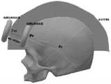
例如,请参阅图7,图7为患者头部模型、安全平面S之间位置关系的一个侧面示意图,假设头部中心点Pc位于患者头部模型中心,目标磁刺激点Pe位于患者头部模型的前额,连接头部中心点Pc与目标磁刺激点Pe,得到直线L,则该直线L与安全平面S存在交点Pm。For example, please refer to Fig. 7, Fig. 7 is a side view of the positional relationship between the patient's head model and the safety plane S. It is assumed that the head center pointPc is located in the center of the patient's head model, and the target magnetic stimulation pointPe is located on the patient's head The forehead of the head model is connected to the head center point Pc and the target magnetic stimulation point Pe to obtain a straight line L, then the straight line L and the safety plane S have an intersection point Pm .
105、根据预设算法生成机械臂的工具中心点从初始位置点Ps移动到交点Pm的第一段路径。105. Generate a first segment of a path in which the tool center point of the robotic arm moves from the initial position point Ps to the intersection point Pm according to a preset algorithm.
可以理解的是,在经颅磁刺激技术中,磁刺激线圈安装在机械臂的末端,即机械臂的末端适配安装有磁刺激线圈,机械臂的工具中心点位于磁刺激线圈的自由端表面,机械臂的工具中心点的坐标值等于机械臂自由端中心点坐标的坐标值(已知)加上磁刺激线圈厚度值所对应的坐标值,避免机械臂在由从初始位置点Ps到交点Pm的第一段路径过程中由于刺激线圈的体积造成的碰撞接触。机械臂的工具中心点一般是指机械臂末端安装的工具(例如磁刺激线圈)的中心点(Tool Central Point,TCP)。例如,请参阅图10,“8”字型的磁刺激线圈适配安装在机械臂自由端,此时假如原本机械臂所在的空间坐标系中该机械臂自由端中心点坐标为(0,0,0),且该机械臂自由端中心点在机械臂的末端坐标系的z轴正方向上,而“8”字型的磁刺激线圈存在2个单位的厚度,那么可以将(0,0,2)设为新的机械臂的工具中心点,从而校准偏差。并且机械臂末端是从远处逐渐向患者头部靠近的,所以本步骤先根据预设算法生成机械臂的工具中心点从初始位置点Ps移动到交点Pm的第一段路径,例如,图7所示从初始位置点Ps移动到交点Pm的曲线部分即为第一段路径。需要说明的是,此处的预设算法可以是人工势场法、蚁群算法、RRT算法、A*算法等,在此对该预设算法的种类方式不进行限定。It can be understood that in the transcranial magnetic stimulation technology, the magnetic stimulation coil is installed at the end of the mechanical arm, that is, the end of the mechanical arm is fitted with the magnetic stimulation coil, and the tool center point of the mechanical arm is located on the free end surface of the magnetic stimulation coil. , the coordinate value of the tool center point of the manipulator is equal to the coordinate value (known) of the coordinate value of the center point of the free end of the manipulator plus the coordinate value corresponding to the thickness value of the magnetic stimulation coil, so as to avoid the manipulator from the initial position point Ps to Collision contact due to the volume of the stimulation coil during the first segment of the path at the intersectionPm . The tool center point of the manipulator generally refers to the center point (Tool Central Point, TCP) of a tool (eg, a magnetic stimulation coil) installed at the end of the manipulator. For example, please refer to Figure 10, the "8"-shaped magnetic stimulation coil is adapted to be installed at the free end of the manipulator. At this time, if the coordinate of the center point of the free end of the manipulator in the space coordinate system where the manipulator is located is (0, 0 , 0), and the center point of the free end of the manipulator is in the positive direction of the z-axis of the end coordinate system of the manipulator, and the "8"-shaped magnetic stimulation coil has a thickness of 2 units, then (0, 0, 2) Set as the tool center point of the new robotic arm to calibrate the deviation. And the end of the robotic arm is gradually approaching the patient's head from a distance, so this step first generates the first segment of the path where the tool center point of the robotic arm moves from the initial position point Ps to the intersection point Pm according to the preset algorithm, for example, The curve part moving from the initial position point Ps to the intersection point Pm shown in FIG. 7 is the first segment of the path. It should be noted that the preset algorithm here may be an artificial potential field method, an ant colony algorithm, an RRT algorithm, an A* algorithm, etc., and the types and manners of the preset algorithm are not limited here.
106、计算交点Pm到目标磁刺激点Pe的距离d,得到第二段路径。106. Calculate the distance d from the intersection point Pm to the target magnetic stimulation pointPe , to obtain the second segment of the path.
具体的,距离d的计算过程包括:Specifically, the calculation process of the distance d includes:

其中(Xm,Ym,Zm)表示交点Pm的坐标;(Xe,Ye,Ze)表示目标磁刺激点Pe的坐标。例如,请参阅图8,图8为磁刺激线圈从安全平面S上的交点Pm运动到患者头部模型的目标磁刺激点Pe的一个示意图。(Xm , Ym , Zm ) represent the coordinates of the intersection point Pm ; (Xe , Ye , Ze ) represent the coordinates of the target magnetic stimulation point Pe . For example, please refer to FIG. 8 , which is a schematic diagram of the magnetic stimulation coil moving from the intersection point Pm on the safety plane S to the target magnetic stimulation pointPe of the patient head model.
107、按先后顺序连接第一段路径与第二段路径,得到机械臂的规划路径。107. Connect the first segment of the path and the second segment of the path in sequence to obtain the planned path of the robotic arm.
在步骤105得到机械臂的工具中心点从初始位置点Ps移动到交点Pm的第一段路径,并在步骤106得到从交点Pm到目标磁刺激点Pe的距离d,那么本步骤则可以按先后顺序连接第一段路径与第二段路径,得到机械臂的规划路径。In
可见,当磁刺激线圈位于机械臂的工具中心点时,机械臂可以按照该规划路径指挥机械臂的工具中心点从初始位置点Ps运动到目标磁刺激点Pe,实现对经颅磁刺激导航过程中机械臂的路径规划导航。It can be seen that when the magnetic stimulation coil is located at the tool center point of the robot arm, the robot arm can instruct the tool center point of the robot arm to move from the initial position point Ps to the target magnetic stimulation pointPe according to the planned path, so as to realize the transcranial magnetic stimulation Path planning and navigation of the robotic arm during navigation.
请参阅图2,在上述图1实施例的基础上,为了进一步避免机械臂在由从初始位置点Ps到交点Pm的第一段路径过程中由于刺激线圈的体积造成与患者头部的碰撞接触,本申请经颅磁刺激导航过程的路径规划方法的另一个实施例,还可以包括:Referring to FIG. 2, on the basis of the above-mentioned embodiment of FIG. 1, in order to further avoid the contact between the robotic arm and the patient's head due to the volume of the stimulation coil during the first path from the initial position point Ps to the intersection point Pm Collision contact, another embodiment of the path planning method for the transcranial magnetic stimulation navigation process of the present application, may also include:
201、设机械臂的工具中心点为起点,患者头部中心点为终点,形成向量M。201. Set the tool center point of the robotic arm as the starting point, and the patient's head center point as the end point, to form a vector M.
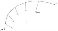
该向量M在机械臂所在的空间坐标系中,不管如何移动都会指向患者头部模型的中心点。如图9所示,图9为图7中第一段路径的初始位置点Ps到交点Pm的不同位置向量M的朝向示意图。The vector M is in the space coordinate system where the robotic arm is located, no matter how it moves, it will point to the center point of the patient's head model. As shown in FIG. 9 , FIG. 9 is a schematic diagram of the orientation of different position vectors M from the initial position point Ps of the first segment of the path to the intersection point Pm in FIG. 7 .
202、将向量M应用于机械臂的磁刺激线圈,使得机械臂的控制磁刺激线圈始终朝向患者头部中心点。202. Apply the vector M to the magnetic stimulation coil of the manipulator, so that the control magnetic stimulation coil of the manipulator always faces the center point of the patient's head.
具体的,将步骤201形成的向量M应用于机械臂的磁刺激线圈,即将该向量M应用于磁刺激线圈所在机械臂末端的一个或多个关节电机,使得该机械臂一直保持该磁刺激线圈始终朝向患者头部中心点。Specifically, the vector M formed in
可以理解的是,若磁刺激线圈在第一段路径运动过程中姿态不确定,则磁刺激线圈本身的体积可能与患者头部有接触的可能,故规定磁刺激线圈始终朝向患者头部中心点,即与安全平面S对应位置切平面平行,这样姿态的磁刺激线圈只受到线圈厚度的影响,而此影响在图1实施例中已排除,故避免了第一段路径执行过程中磁刺激线圈与头部表面接触的可能。It is understandable that if the magnetic stimulation coil has an uncertain posture during the movement of the first segment of the path, the volume of the magnetic stimulation coil may be in contact with the patient's head, so it is specified that the magnetic stimulation coil always faces the center of the patient's head. , that is, it is parallel to the tangent plane corresponding to the safety plane S, so that the magnetic stimulation coil in this posture is only affected by the thickness of the coil, and this influence has been eliminated in the embodiment of FIG. 1, so the magnetic stimulation coil during the execution of the first path is avoided. Potential for contact with head surface.
203、将向量M的方向作为磁刺激线圈所在的机械臂的末端坐标系的z轴方向。203. Use the direction of the vector M as the z-axis direction of the end coordinate system of the robotic arm where the magnetic stimulation coil is located.
具体的,为了便于第二段路径的执行,本步骤可以将向量M的方向作为磁刺激线圈所在的机械臂的末端坐标系的z轴方向(请参阅图10所示),再由机械臂工具中心点坐标求出与z轴垂直的包含机械臂工具中心点坐标的平面方程,在该平面方程所代表的平面上任取两个以机械臂工具中心点坐标为交点的相互垂直的直线,建立正交坐标系,得到机械臂末端坐标系,在该机械臂末端坐标系中可以求得磁刺激线圈的位姿,进而具体控制磁刺激线圈呈现向量M的位姿。Specifically, in order to facilitate the execution of the second segment of the path, in this step, the direction of the vector M can be used as the z-axis direction of the end coordinate system of the robotic arm where the magnetic stimulation coil is located (see Figure 10), and then the robotic arm tool The coordinate of the center point is to find the plane equation that is perpendicular to the z-axis and contains the coordinates of the center point of the manipulator tool. On the plane represented by the plane equation, two perpendicular straight lines with the coordinate of the center point of the manipulator tool as the intersection point are chosen to establish a positive The coordinate system of the end of the manipulator is obtained, and the pose of the magnetic stimulation coil can be obtained in the coordinate system of the end of the manipulator, and then the pose of the vector M can be specifically controlled by the magnetic stimulation coil.
本实施例经颅磁刺激导航过程的路径规划可以在机械臂所在的空间坐标系进行,也可以在双目视觉相机坐标系中进行等进行,进而得到规划路径。当本实施例经颅磁刺激导航过程的路径规划不在机械臂所在的空间坐标系进行时,为了使得机械臂能得知该路径规划,实现经颅磁刺激导航的过程,请参阅图3,本申请经颅磁刺激导航过程的路径规划方法的另一个实施例,包括:The path planning of the transcranial magnetic stimulation navigation process in this embodiment may be performed in the space coordinate system where the robotic arm is located, or may be performed in the coordinate system of the binocular vision camera, etc., so as to obtain the planned path. When the path planning of the transcranial magnetic stimulation navigation process in this embodiment is not performed in the space coordinate system where the robotic arm is located, in order to enable the robotic arm to know the path planning and realize the process of transcranial magnetic stimulation navigation, please refer to FIG. Another embodiment of a path planning method for a transcranial magnetic stimulation navigation process, comprising:
301、将规划路径转化为机械臂的空间坐标系下的运动路径。301. Convert the planned path into a motion path in the space coordinate system of the robotic arm.
将其他坐标系下形成的规划路径转化为机械臂的空间坐标系下的运动路径,例如,将双目视觉相机坐标系下形成的机械臂的规划路径,按照双目视觉相机坐标系与机械臂的空间坐标系的转换关系转化为机械臂的空间坐标系下的运动路径。Convert the planned paths formed in other coordinate systems into the motion paths of the robotic arm in the space coordinate system. The transformation relationship of the space coordinate system is transformed into the motion path under the space coordinate system of the manipulator.
302、将运动路径发送给机械臂,以使得机械臂的工具中心点沿着运动路径运动。302. Send the motion path to the robotic arm, so that the tool center point of the robotic arm moves along the motion path.
将步骤30转化的运动路径发送给机械臂,以使得运动路径在机械臂所在的空间坐标系对应生成,进而使得机械臂可以指挥其工具中心点可以沿着运动路径运动,完成对运动路径的执行,实现对经颅磁刺激导航过程的路径规划的执行。Send the motion path transformed in step 30 to the manipulator, so that the motion path is correspondingly generated in the space coordinate system where the manipulator is located, so that the manipulator can instruct its tool center point to move along the motion path, and complete the execution of the motion path , to realize the execution of the path planning for the transcranial magnetic stimulation navigation process.
上述实施例对本申请经颅磁刺激导航过程的路径规划方法进行了描述,下面对本申请经颅磁刺激导航过程的路径规划系统进行描述,请参阅图4,经颅磁刺激导航过程的路径规划系统的一个实施例,应用于机械臂,包括:The above embodiment describes the path planning method of the transcranial magnetic stimulation navigation process of the present application, and the path planning system of the transcranial magnetic stimulation navigation process of the present application is described below, please refer to FIG. 4, the path planning system of the transcranial magnetic stimulation navigation process An embodiment of , applied to a robotic arm, includes:
确定单元401,用于确定患者头部的头部中心点Pc、所述患者头部的目标磁刺激点Pe、所述机械臂的工具中心点的初始位置点Ps;A
创建单元402,用于以所述头部中心点Pc为球心,预设长度R为半径,创建空间半球体,所述空间半球体包裹所述患者头部的所有磁刺激点;A
作为单元403,用于将所述空间半球体的外表面作为安全平面S;As the
连接单元404,用于连接所述头部中心点Pc与所述目标磁刺激点Pe,得到直线L,所述直线L与所述安全平面S存在交点Pm;a connecting
生成单元405,用于根据预设算法生成所述机械臂的工具中心点从所述初始位置点Ps移动到所述交点Pm的第一段路径;A generating
计算单元406,用于计算所述交点Pm到所述目标磁刺激点Pe的距离d,得到第二段路径;A
连接单元404,还用于按先后顺序连接所述第一段路径与所述第二段路径,得到所述机械臂的规划路径。The connecting
可选的,所述确定单元401确定患者头部中心点的头部中心点Pc时,具体用于:Optionally, when the determining
使用AABB包围盒算法对所述患者头部进行包围计算,得到对所述患者头部的包围盒;using the AABB bounding box algorithm to enclose the patient's head to obtain a bounding box of the patient's head;
计算所述包围盒的中心点坐标;Calculate the coordinates of the center point of the bounding box;
将所述包围盒的中心点坐标视为所述患者头部中心点的所述头部中心点Pc的坐标。The coordinates of the center point of the bounding box are regarded as the coordinates of the head center point Pc of the patient's head center point.
可选的,所述预设长度R包括:Optionally, the preset length R includes:

其中所述(Xc,Yc,Zc)表示所述头部中心点Pc的坐标;wherein (Xc , Yc , Zc ) represents the coordinates of the center point Pc of the head;
所述(Xn,Yn,Zn)表示所述包围盒上到所述头部中心点Pc距离最大的包围盒最远点的坐标。The (Xn , Yn , Zn ) represents the coordinates of the farthest point of the bounding box with the largest distance from the head center point Pc on the bounding box.
可选的,计算单元计算所述交点Pm到所述目标磁刺激点Pe的距离d时,具体用于:Optionally, when the computing unit calculates the distance d from the intersection point Pm to the target magnetic stimulation point Pe , it is specifically used for:

其中所述(Xm,Ym,Zm)表示所述交点Pm的坐标;wherein the (Xm , Ym , Zm ) represents the coordinates of the intersection point Pm ;
所述(Xe,Ye,Ze)表示所述目标磁刺激点Pe的坐标。The (Xe ,Ye ,Ze ) represents the coordinates of the target magnetic stimulation point Pe.
可选的,所述机械臂的末端适配安装有磁刺激线圈,所述机械臂的工具中心点位于所述磁刺激线圈的自由端表面,所述机械臂的工具中心点的坐标值等于所述机械臂自由端中心点坐标加上磁刺激线圈厚度值所对应的坐标值。Optionally, the end of the robotic arm is fitted with a magnetic stimulation coil, the tool center point of the robotic arm is located on the free end surface of the magnetic stimulation coil, and the coordinate value of the tool center point of the robotic arm is equal to all The coordinate value corresponding to the center point coordinate of the free end of the manipulator plus the thickness value of the magnetic stimulation coil.
可选的,还包括:Optionally, also include:
创建单元,还用于设所述机械臂的工具中心点为起点,所述患者头部中心点为终点,形成向量M;The creation unit is also used to set the tool center point of the robotic arm as the starting point, and the patient's head center point as the end point, forming a vector M;
作为单元,还用于将所述向量M应用于所述机械臂的所述磁刺激线圈,使得所述机械臂的控制所述磁刺激线圈始终朝向所述患者头部中心点。As a unit, it is also used to apply the vector M to the magnetic stimulation coil of the robotic arm, so that the magnetic stimulation coil of the robotic arm is always directed toward the center point of the patient's head.
可选的,所述系统还包括:Optionally, the system further includes:
作为单元,还用于将所述向量M的方向作为所述磁刺激线圈所在的所述机械臂的末端坐标系的z轴方向。As a unit, it is also used to take the direction of the vector M as the z-axis direction of the end coordinate system of the robotic arm where the magnetic stimulation coil is located.
可选的,所述系统还包括:Optionally, the system further includes:
转化单元407,用于将所述规划路径转化为机械臂的空间坐标系下的运动路径;A
发送单元408,用于将所述运动路径发送给所述机械臂,以使得所述机械臂的所述工具中心点沿着所述运动路径运动。A sending
本申请实施例经颅磁刺激导航过程的路径规划系统,其所执行的操作与前述图1、图2以及图3实施例中所执行的操作类似,在此不再进行赘述。The operations performed by the path planning system for the transcranial magnetic stimulation navigation process according to the embodiment of the present application are similar to those performed in the foregoing embodiments in FIGS.
下面对本申请实施例的计算机设备进行描述,请参阅图5,本申请实施例中计算机设备的一个实施例包括:The computer device according to the embodiment of the present application will be described below. Please refer to FIG. 5. An example of the computer device in the embodiment of the present application includes:
该计算机设备500可以包括一个或一个以上处理器(central processing units,CPU)501和存储器502,该存储器502中存储有一个或一个以上的应用程序或数据。其中,存储器502是易失性存储或持久存储。存储在存储器502的程序可以包括一个或一个以上模块,每个模块可以包括对计算机设备中的一系列指令操作。更进一步地,处理器501可以设置为与存储器502通信,在计算机设备500上执行存储器502中的一系列指令操作。计算机设备500还可以包括一个或一个以上网络接口503,一个或一个以上输入输出接口504,和/或,一个或一个以上操作系统,例如Windows Server,Mac OS,Unix,Linux,FreeBSD等。该处理器501可以执行前述图1至图3所示实施例中所执行的操作,具体此处不再赘述。The
在本申请实施例所提供的几个实施例中,本领域技术人员应该理解到,所揭露的系统,装置和方法,可以通过其它的方式实现。例如,以上所描述的装置实施例仅仅是示意性的,例如,该单元的划分,仅仅为一种逻辑功能划分,实际实现时可以有另外的划分方式,例如多个单元或组件可以结合或者可以集成到另一个系统,或一些特征可以忽略,或不执行。In the several embodiments provided by the embodiments of the present application, those skilled in the art should understand that the disclosed systems, devices and methods may be implemented in other manners. For example, the apparatus embodiments described above are only illustrative. For example, the division of the unit is only a logical function division. In actual implementation, there may be other division methods, for example, multiple units or components may be combined or Integration into another system, or some features can be ignored, or not implemented.
另外,在本申请各个实施例中的各功能单元可以集成在一个处理单元中,也可以是各个单元单独物理存在,也可以两个或两个以上单元集成在一个单元中。上述集成的单元既可以采用硬件的形式实现,也可以采用软件功能单元的形式实现。集成的单元如果以软件功能单元的形式实现并作为独立的产品销售或使用时,可以存储在一个计算机可读取存储介质中。基于这样的理解,本申请的技术方案本质上或者说对现有技术做出贡献的部分或者该技术方案的全部或部分可以以软件产品的形式体现出来,该计算机软件产品存储在一个存储介质中,包括若干指令用以使得一台计算机设备(可以是个人计算机,服务器,或者网络设备等)执行本申请各个实施例方法的全部或部分步骤。而前述的存储介质包括:U盘、移动硬盘、只读存储器(ROM,read-only memory)、随机存取存储器(RAM,randomaccess memory)、磁碟或者光盘等各种可以存储程序代码的介质。In addition, each functional unit in each embodiment of the present application may be integrated into one processing unit, or each unit may exist physically alone, or two or more units may be integrated into one unit. The above-mentioned integrated units may be implemented in the form of hardware, or may be implemented in the form of software functional units. The integrated unit, if implemented as a software functional unit and sold or used as a stand-alone product, may be stored in a computer-readable storage medium. Based on this understanding, the technical solutions of the present application can be embodied in the form of software products in essence, or the parts that contribute to the prior art, or all or part of the technical solutions, and the computer software products are stored in a storage medium , including several instructions to cause a computer device (which may be a personal computer, a server, or a network device, etc.) to execute all or part of the steps of the methods in the various embodiments of the present application. The aforementioned storage medium includes: U disk, removable hard disk, read-only memory (ROM, read-only memory), random access memory (RAM, random access memory), magnetic disk or optical disk and other media that can store program codes.
以上所述仅为本申请的较佳实施例而已,并不用以限制本申请,凡在本申请的精神和原则之内所作的任何修改、等同替换或改进等,均应包含在本申请的保护范围之内。The above descriptions are only preferred embodiments of the present application and are not intended to limit the present application. Any modifications, equivalent replacements or improvements made within the spirit and principles of the present application shall be included in the protection of the present application. within the range.
Claims (10)
Translated fromChinese

Priority Applications (1)
| Application Number | Priority Date | Filing Date | Title |
|---|---|---|---|
| CN202210118451.XACN114504735A (en) | 2022-02-08 | 2022-02-08 | Path planning method and related device for transcranial magnetic stimulation navigation process |
Applications Claiming Priority (1)
| Application Number | Priority Date | Filing Date | Title |
|---|---|---|---|
| CN202210118451.XACN114504735A (en) | 2022-02-08 | 2022-02-08 | Path planning method and related device for transcranial magnetic stimulation navigation process |
Publications (1)
| Publication Number | Publication Date |
|---|---|
| CN114504735Atrue CN114504735A (en) | 2022-05-17 |
Family
ID=81552485
Family Applications (1)
| Application Number | Title | Priority Date | Filing Date |
|---|---|---|---|
| CN202210118451.XAPendingCN114504735A (en) | 2022-02-08 | 2022-02-08 | Path planning method and related device for transcranial magnetic stimulation navigation process |
Country Status (1)
| Country | Link |
|---|---|
| CN (1) | CN114504735A (en) |
Cited By (1)
| Publication number | Priority date | Publication date | Assignee | Title |
|---|---|---|---|---|
| CN114795474A (en)* | 2022-06-01 | 2022-07-29 | 苏州脑控脑科学技术有限公司 | Navigation transcranial magnetic path planning method and device and electronic equipment |
Citations (4)
| Publication number | Priority date | Publication date | Assignee | Title |
|---|---|---|---|---|
| US20170354832A1 (en)* | 2016-06-13 | 2017-12-14 | The Board Of Trustees Of The Leland Stanford Junior University | Trajectory Optimization in Radiotherapy Using Sectioning |
| CN111840804A (en)* | 2020-08-03 | 2020-10-30 | 南京伟思医疗科技股份有限公司 | A kind of transcranial magnetic stimulation repetitive positioning helmet and using method thereof |
| CN112933599A (en)* | 2021-04-08 | 2021-06-11 | 腾讯科技(深圳)有限公司 | Three-dimensional model rendering method, device, equipment and storage medium |
| CN113561186A (en)* | 2021-09-24 | 2021-10-29 | 季华实验室 | Evaluation method for manipulator path planning result |
- 2022
- 2022-02-08CNCN202210118451.XApatent/CN114504735A/enactivePending
Patent Citations (4)
| Publication number | Priority date | Publication date | Assignee | Title |
|---|---|---|---|---|
| US20170354832A1 (en)* | 2016-06-13 | 2017-12-14 | The Board Of Trustees Of The Leland Stanford Junior University | Trajectory Optimization in Radiotherapy Using Sectioning |
| CN111840804A (en)* | 2020-08-03 | 2020-10-30 | 南京伟思医疗科技股份有限公司 | A kind of transcranial magnetic stimulation repetitive positioning helmet and using method thereof |
| CN112933599A (en)* | 2021-04-08 | 2021-06-11 | 腾讯科技(深圳)有限公司 | Three-dimensional model rendering method, device, equipment and storage medium |
| CN113561186A (en)* | 2021-09-24 | 2021-10-29 | 季华实验室 | Evaluation method for manipulator path planning result |
Non-Patent Citations (2)
| Title |
|---|
| 姚寿文 等: "《虚拟现实辅助机械设计》", 31 July 2020, 北京理工大学出版社, pages: 95 - 98* |
| 王贺 等: ""机器人辅助经颅磁刺激线圈定位的导航路径规划与避障算法研究"", 《研究与设计》, vol. 40, no. 6, 31 December 2019 (2019-12-31), pages 1 - 7* |
Cited By (1)
| Publication number | Priority date | Publication date | Assignee | Title |
|---|---|---|---|---|
| CN114795474A (en)* | 2022-06-01 | 2022-07-29 | 苏州脑控脑科学技术有限公司 | Navigation transcranial magnetic path planning method and device and electronic equipment |
Similar Documents
| Publication | Publication Date | Title |
|---|---|---|
| CN108883533B (en) | Robot control | |
| Wang et al. | Visual servo control of cable-driven soft robotic manipulator | |
| CN100549889C (en) | The control of operating control track | |
| Ryden et al. | Forbidden-region virtual fixtures from streaming point clouds: Remotely touching and protecting a beating heart | |
| AU2018282197A1 (en) | Robotic system and method for producing reactive forces to implement virtual boundaries | |
| US11999061B2 (en) | Method and system for autonomous object manipulation | |
| CN114571469A (en) | Zero-space real-time obstacle avoidance control method and system for mechanical arm | |
| Kim et al. | Predicting redundancy of a 7 dof upper limb exoskeleton toward improved transparency between human and robot | |
| CN114376726B (en) | Path planning method and related device for transcranial magnetic stimulation navigation process | |
| CN113742992B (en) | Master-slave control method based on deep learning and application | |
| CN112936288B (en) | Robot action safety detection method and device, electronic equipment and storage medium | |
| CN114504735A (en) | Path planning method and related device for transcranial magnetic stimulation navigation process | |
| CN114952838A (en) | A robot arm joint trajectory planning method based on end measurement feedback | |
| CN108153957A (en) | Space manipulator kinetics simulation analysis method, system and storage medium | |
| CN114800528A (en) | Mobile manipulator repetitive motion planning for non-convex anti-noise type return-to-zero neural network | |
| CN116690564A (en) | Control method and system of massage robot | |
| Yang et al. | Human-robot shared control system based on 3D point cloud and teleoperation | |
| Chang et al. | Model-based manipulation of linear flexible objects with visual curvature feedback | |
| WO2023030035A1 (en) | Dynamic picture dynamic display method for position of mechanical arm and control terminal | |
| Kastritsi et al. | A passive control framework for a bilateral leader-follower robotic surgical setup imposing RCM and active constraints | |
| Melo et al. | Adaptive admittance control to generate real-time assistive fixtures for a cobot in transpedicular fixation surgery | |
| CN115731285A (en) | Robot terminal control method, device, electronic equipment and storage medium | |
| Lebossé et al. | A robotic system for automated image-guided transcranial magnetic stimulation | |
| CN118415756A (en) | Motion simulation control method, device, medium and product of surgical navigation robot | |
| Chen et al. | Automatic field of view control of laparoscopes with soft RCM constraints |
Legal Events
| Date | Code | Title | Description |
|---|---|---|---|
| PB01 | Publication | ||
| PB01 | Publication | ||
| SE01 | Entry into force of request for substantive examination | ||
| SE01 | Entry into force of request for substantive examination |